EP2090523A1 - An interlayer insert for palettisation - Google Patents
An interlayer insert for palettisation Download PDFInfo
- Publication number
- EP2090523A1 EP2090523A1 EP08101647A EP08101647A EP2090523A1 EP 2090523 A1 EP2090523 A1 EP 2090523A1 EP 08101647 A EP08101647 A EP 08101647A EP 08101647 A EP08101647 A EP 08101647A EP 2090523 A1 EP2090523 A1 EP 2090523A1
- Authority
- EP
- European Patent Office
- Prior art keywords
- insert
- pallet
- flap
- interlayer
- flaps
- Prior art date
- Legal status (The legal status is an assumption and is not a legal conclusion. Google has not performed a legal analysis and makes no representation as to the accuracy of the status listed.)
- Withdrawn
Links
- 239000011229 interlayer Substances 0.000 title claims abstract description 44
- 239000010410 layer Substances 0.000 claims abstract description 35
- 239000010408 film Substances 0.000 claims description 6
- 239000000463 material Substances 0.000 claims description 6
- 239000002356 single layer Substances 0.000 claims description 4
- 229920001169 thermoplastic Polymers 0.000 claims description 4
- 239000004416 thermosoftening plastic Substances 0.000 claims description 4
- 239000002023 wood Substances 0.000 claims description 4
- 229920000114 Corrugated plastic Polymers 0.000 claims description 3
- 229920005830 Polyurethane Foam Polymers 0.000 claims description 2
- 239000004794 expanded polystyrene Substances 0.000 claims description 2
- 239000006260 foam Substances 0.000 claims description 2
- 239000003292 glue Substances 0.000 claims description 2
- 239000002245 particle Substances 0.000 claims description 2
- 229920000642 polymer Polymers 0.000 claims description 2
- 239000011496 polyurethane foam Substances 0.000 claims description 2
- 238000012986 modification Methods 0.000 description 3
- 230000004048 modification Effects 0.000 description 3
- 239000005022 packaging material Substances 0.000 description 3
- 238000004806 packaging method and process Methods 0.000 description 3
- 230000007613 environmental effect Effects 0.000 description 2
- 238000000034 method Methods 0.000 description 2
- 238000004026 adhesive bonding Methods 0.000 description 1
- 230000001427 coherent effect Effects 0.000 description 1
- 238000010276 construction Methods 0.000 description 1
- 230000003247 decreasing effect Effects 0.000 description 1
- 230000003467 diminishing effect Effects 0.000 description 1
- 230000003993 interaction Effects 0.000 description 1
- 239000002184 metal Substances 0.000 description 1
- 239000000203 mixture Substances 0.000 description 1
- 238000012856 packing Methods 0.000 description 1
- 239000000123 paper Substances 0.000 description 1
- 239000004033 plastic Substances 0.000 description 1
- 229920003023 plastic Polymers 0.000 description 1
Images



Classifications
-
- B—PERFORMING OPERATIONS; TRANSPORTING
- B65—CONVEYING; PACKING; STORING; HANDLING THIN OR FILAMENTARY MATERIAL
- B65D—CONTAINERS FOR STORAGE OR TRANSPORT OF ARTICLES OR MATERIALS, e.g. BAGS, BARRELS, BOTTLES, BOXES, CANS, CARTONS, CRATES, DRUMS, JARS, TANKS, HOPPERS, FORWARDING CONTAINERS; ACCESSORIES, CLOSURES, OR FITTINGS THEREFOR; PACKAGING ELEMENTS; PACKAGES
- B65D71/00—Bundles of articles held together by packaging elements for convenience of storage or transport, e.g. portable segregating carrier for plural receptacles such as beer cans or pop bottles; Bales of material
- B65D71/0088—Palletisable loads, i.e. loads intended to be transported by means of a fork-lift truck
- B65D71/0092—Palletisable loads, i.e. loads intended to be transported by means of a fork-lift truck provided with one or more rigid supports, at least one dimension of the supports corresponding to a dimension of the load, e.g. skids
- B65D71/0096—Palletisable loads, i.e. loads intended to be transported by means of a fork-lift truck provided with one or more rigid supports, at least one dimension of the supports corresponding to a dimension of the load, e.g. skids the dimensions of the supports corresponding to the periphery of the load, e.g. pallets
-
- B—PERFORMING OPERATIONS; TRANSPORTING
- B65—CONVEYING; PACKING; STORING; HANDLING THIN OR FILAMENTARY MATERIAL
- B65D—CONTAINERS FOR STORAGE OR TRANSPORT OF ARTICLES OR MATERIALS, e.g. BAGS, BARRELS, BOTTLES, BOXES, CANS, CARTONS, CRATES, DRUMS, JARS, TANKS, HOPPERS, FORWARDING CONTAINERS; ACCESSORIES, CLOSURES, OR FITTINGS THEREFOR; PACKAGING ELEMENTS; PACKAGES
- B65D57/00—Internal frames or supports for flexible articles, e.g. stiffeners; Separators for articles packaged in stacks or groups, e.g. for preventing adhesion of sticky articles
- B65D57/002—Separators for articles packaged in stacks or groups, e.g. stacked or nested
- B65D57/003—Separators for articles packaged in stacks or groups, e.g. stacked or nested for horizontally placed articles, i.e. for stacked or nested articles
-
- B—PERFORMING OPERATIONS; TRANSPORTING
- B65—CONVEYING; PACKING; STORING; HANDLING THIN OR FILAMENTARY MATERIAL
- B65D—CONTAINERS FOR STORAGE OR TRANSPORT OF ARTICLES OR MATERIALS, e.g. BAGS, BARRELS, BOTTLES, BOXES, CANS, CARTONS, CRATES, DRUMS, JARS, TANKS, HOPPERS, FORWARDING CONTAINERS; ACCESSORIES, CLOSURES, OR FITTINGS THEREFOR; PACKAGING ELEMENTS; PACKAGES
- B65D2571/00—Bundles of articles held together by packaging elements for convenience of storage or transport, e.g. portable segregating carrier for plural receptacles such as beer cans, pop bottles; Bales of material
- B65D2571/00006—Palletisable loads, i.e. loads intended to be transported by means of a fork-lift truck
- B65D2571/00043—Intermediate plates or the like
-
- B—PERFORMING OPERATIONS; TRANSPORTING
- B65—CONVEYING; PACKING; STORING; HANDLING THIN OR FILAMENTARY MATERIAL
- B65D—CONTAINERS FOR STORAGE OR TRANSPORT OF ARTICLES OR MATERIALS, e.g. BAGS, BARRELS, BOTTLES, BOXES, CANS, CARTONS, CRATES, DRUMS, JARS, TANKS, HOPPERS, FORWARDING CONTAINERS; ACCESSORIES, CLOSURES, OR FITTINGS THEREFOR; PACKAGING ELEMENTS; PACKAGES
- B65D2571/00—Bundles of articles held together by packaging elements for convenience of storage or transport, e.g. portable segregating carrier for plural receptacles such as beer cans, pop bottles; Bales of material
- B65D2571/00006—Palletisable loads, i.e. loads intended to be transported by means of a fork-lift truck
- B65D2571/00067—Local maintaining elements, e.g. partial packaging, shrink packaging, shrink small bands
Definitions
- the present invention concerns a new palettisation system, specifically a 3D palettisation system that improves the overall stability of the pallet formed therewith.
- an interlayer insert for palettisation comprising a substantially horizontal base board to be inserted between two layers of a pallet, each layer comprising a plurality of individual packages, characterized in that said insert further comprises at least one flap extending downwardly and/or at least one flap extending upwardly from said base into said lower and/or upper layer(s) respectively, so that said at least one flap is inserted and maintained between at least two individual packages of the corresponding layer.
- the overall cohesion of the said pallet is highly improved. More particularly, due to the friction of the flap(s) which is/are therefore held in place between the individual packages of the upper and/or lower layers, in additional to the friction forces of the base that is held in place between the upper and lower layers of the said pallet, the whole pallet construction is coherent mechanically, and shows a high resistance to lateral deformation.
- resistance to lateral deformation it is meant resistance to forces applied externally to the pallet in a direction substantially perpendicular to the pallet vertical axis.
- the base of the said insert is substantially flat.
- the insert according to the invention comprises at least two flaps, which can advantageously be disposed along non parallel plans.
- Said flaps can also be disposed along substantially orthogonal plans.
- said at least one flap can advantageously be attached to at least one package of a layer, in a removable manner, for instance by at least one spot of glue.
- the interlayer insert is formed integrally in one piece, such that said at least one flap forms one piece with the base.
- the insert of the invention is made out of a material selected from the list of: monolayer or multilayer cardboard, corrugated cardboard, monolayer or multilayer thermoplastic, corrugated plastic, thermoplastic film, wood or wood particles, expanded polystyrene, polymer foam such as polyurethane foam, or a combination thereof.
- the present invention is further directed to a pallet comprising at least two layers, each layer comprising at least two individual packages, characterized in that said layers are separated by an interlayer insert having any of the above described characteristics.
- the individual packages can be either primary packages such as bottles, cans or containers, or secondary packages such as shrink-filmed or stretch-filmed groups of primary packages.
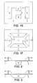
- FIGS 1A to 1 F illustrate different configurations of flat boards 1 for making an interlayer insert for palettisation according to the present invention.
- the boards 1 are made out of any suitable material that is inexpensive, ecological, mechanically resistant, and easy to cut in predetermined configurations and dimensions.
- suitable materials include, but are not limited to, flat cardboard, corrugated cardboard, flat plastic, corrugated plastic, metal sheets, paper, or a combination thereof.
- Each board 1 comprises at least one precut portion 2, preferably at least two.
- Each precut portion 2 illustrated in figure 1A, 1B, 1C, 1D resembles a rectangle which has three of its sides 3 which are completely cut. One remaining side of the precut portion 2 is kept uncut and defines a hinge 4 (shown in dotted lines in the drawing).
- precut 2 - triangular, semi-elliptic, trapezoidal, or else - can be applied, depending on the size, shape or configuration of the packages to stack into an assembly and hold.
- Figure 1E illustrates an alternative flat board 1 for making an interlayer insert according to the invention, wherein the precut portions 2 are rectangular and disposed by pairs in a symmetrical disposition relative to the longitudinal, respectively, transversal axis of the board.
- Figure 1F shows another alternative flat board with 2 pairs of trapezoidal precut zones, each pair comprising precut portions disposed symmetrically around longitudinal, respectively transversal axis of the flat board.
- the precut portions 2 of a flat board 1 are unfolded and deployed, above and/or below the plan of the said flat board, in order to create deployed flaps 6.
- the flaps 6 are deployed at a 90° angle from the board plan, as illustrated in side views 2 to 5.
- Figure 2 shows an interlayer 5 with unfolded flaps 6 deployed at a 90° angle relative to the board plan, along precut portions 2 described above and shown in figure 1E .
- a pair of flaps 6 is deployed above the board plan, while the other pair of flaps 6 is deployed below the said plan.
- the interlayer insert 5 is configured to be mechanically linked to layers 7 of packages 8 disposed above and below the board plan in a packaging assembly.
- Figure 3 illustrates a similar interlayer 5 than the one described above for figure 2 , but wherein the flaps 6 have a trapezoidal shape.
- This interlayer insert 5 is produced from the flat board 1 shown in figure 1 F .
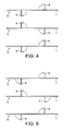
- a stack of interlayers is prepared as shown in figure 4 , as would be installed between layers of a packaging assembly, for instance in a pallet that will be described hereinafter.
- a stack of interlayer inserts 5 with deployed flaps 6 is shown in figures 5 , 6 , or 7 that comprises several interlayer inserts 5 made from flat boards 1 shown in figure 1A or 1B .
- a plurality of interlayer inserts 5 having different configurations of flaps can be gathered and stacked in a pallet.
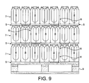
- a pallet 9 can therefore be prepared, as shown in figures 8 or 9 , which illustrate the use of interlayer inserts 5 made from flat boards 1 with flaps configurations shown in figures 1C , 4 , 6 , 7 , and respectively figures 1A, 1 B, and 5 .
- a flap 6 that belongs to the interlayer insert disposed under the bottom layer of a pallet, and should normally be unfolded downwardly, is not deployed as it is directly in contact with the pallet disposed below.
- the interlayer inserts 5 according to the invention are inserted between two layers 7 of the pallet 9.
- Each layer 7 of the pallet 9 comprises a plurality of individual packages 8 disposed in rows.
- each interlayer insert 5 (except the interlayer insert in direct contact with the pallet board) creates a mechanical link between the upper and lower layers 7 of packages 8 between which it is disposed.
- Each interlayer insert 5 is formed integrally in one piece, such that said at least one flap 6 forms one piece with the base board 1.
- each interlayer insert 5 is attached, for instance by gluing to the upper and/or lower layers 7 in the pallet 9.
- the interlayer inserts according to the invention are easy to place into a pallet in an automated way, using conventional palettisation techniques.
- the insert is placed in between layers of packages in the usual way, the flaps being unfolded at the time the interlayer is disposed on the pallet.
- the unfolding operation can be performed manually, however, in a preferred embodiment, this flap-unfolding process is automated. In that case, it could be done by a robot with vacuum pads to manipulate the flaps.
- the same robot could place the packs on the pallet as standard palletizer and had the function to take an interlayer and place it on the layer of the pallet. It could be as well a mix between standard palletizer and a robot for the interlayer.
Landscapes
- Engineering & Computer Science (AREA)
- Mechanical Engineering (AREA)
- Pallets (AREA)
Abstract
Description
- The present invention concerns a new palettisation system, specifically a 3D palettisation system that improves the overall stability of the pallet formed therewith.
- In palettisation systems like other packing and packaging areas, it is more and more important to restrict the amount of packaging material used for cost and environmental reasons, or at least use recyclable materials and systems.
- In the palettisation systems, it is however important to improve the stability of the pallets so that, while the size of a pallet is kept unchanged and the amount of packaging material that is used is decreased, the overall mechanical properties of the pallet are improved.
- Different systems have been developed which involve stretching films for wrapping the pallet once it is constituted, or similar systems. However, such over wrapping film solutions require a specific equipment to wrap the pallet with film, and also require quite a large amount of packaging material, or even several materials.
- In the
French patent FR 2 229 235 to Alfred Weibel - It is therefore a main purpose of the present invention to provide an alternative interlayer insert to the existing systems, that solves the above listed disadvantages and issues. It is for instance a purpose of the present invention to provide a new interlayer insert for pallets, that is cheap, if possible recyclable, provides a good stability to the pallet and decrease or even removes the need for additional overwrapping film to hold the pallet together in a stable configuration, while having a reduced environmental impact.
- The above listed purpose and needs are met by the present invention with an interlayer insert for palettisation comprising a substantially horizontal base board to be inserted between two layers of a pallet, each layer comprising a plurality of individual packages, characterized in that said insert further comprises at least one flap extending downwardly and/or at least one flap extending upwardly from said base into said lower and/or upper layer(s) respectively, so that said at least one flap is inserted and maintained between at least two individual packages of the corresponding layer.
- Due to the mechanical interaction of the flap or flaps with upper and/or lower layers of the pallet, the overall cohesion of the said pallet is highly improved. More particularly, due to the friction of the flap(s) which is/are therefore held in place between the individual packages of the upper and/or lower layers, in additional to the friction forces of the base that is held in place between the upper and lower layers of the said pallet, the whole pallet construction is coherent mechanically, and shows a high resistance to lateral deformation.
- By "resistance to lateral deformation", it is meant resistance to forces applied externally to the pallet in a direction substantially perpendicular to the pallet vertical axis.
- Preferably, the base of the said insert is substantially flat.
- Also preferably, the insert according to the invention comprises at least two flaps, which can advantageously be disposed along non parallel plans.
- Said flaps can also be disposed along substantially orthogonal plans.
- In another possible embodiment of the invention, said at least one flap can advantageously be attached to at least one package of a layer, in a removable manner, for instance by at least one spot of glue.
- In a highly preferred embodiment of the invention, the interlayer insert is formed integrally in one piece, such that said at least one flap forms one piece with the base.
- Preferably, the insert of the invention is made out of a material selected from the list of: monolayer or multilayer cardboard, corrugated cardboard, monolayer or multilayer thermoplastic, corrugated plastic, thermoplastic film, wood or wood particles, expanded polystyrene, polymer foam such as polyurethane foam, or a combination thereof.
- The present invention is further directed to a pallet comprising at least two layers, each layer comprising at least two individual packages, characterized in that said layers are separated by an interlayer insert having any of the above described characteristics.
- In such a pallet, the individual packages can be either primary packages such as bottles, cans or containers, or secondary packages such as shrink-filmed or stretch-filmed groups of primary packages.
- Additional features and advantages of the present invention are described in, and will be apparent from, the description of the presently preferred embodiments which are set out below with reference to the drawings in which:
-
Figures 1A to 1F are schematic top views showing flat boards with different configurations of precut flaps for making interlayer panels according to the invention ; -
Figure 2 is a schematic side view of the interlayer board shown infigure 1 E with flaps deployed ; -
Figure 3 is a schematic side view of the interlayer board shown infigure 1 F with flaps deployed ; -
Figure 4 is a schematic side view showing a plurality of superimposed interlayers made from the board according tofigure 1C , with flaps deployed ; -
Figure 5 is a schematic side view showing a plurality of superimposed interlayers made from the boards according tofigure 1A and 1 B , with flaps deployed ; -
Figure 6 is a schematic perspective view showing a plurality of superimposed interlayers similar tofigure 4 ; -
Figure 7 is a schematic perspective view similar tofigure 6 , wherein the plurality of interlayers is disposed above a pallet ; -
Figure 8 is a schematic side view similar tofigure 7 , showing interlayers in place into a pallet, holding secondary packages (groups of bottles) ; -
Figure 9 is a view similar tofigure 8 , showing a configuration of interlayer boards formed from the flat boards illustrated infigures 1A, 1 B, and 5 . -
Figures 1A to 1 F illustrate different configurations offlat boards 1 for making an interlayer insert for palettisation according to the present invention. - The
boards 1 are made out of any suitable material that is inexpensive, ecological, mechanically resistant, and easy to cut in predetermined configurations and dimensions. Such materials include, but are not limited to, flat cardboard, corrugated cardboard, flat plastic, corrugated plastic, metal sheets, paper, or a combination thereof. - Each
board 1 comprises at least oneprecut portion 2, preferably at least two. Eachprecut portion 2 illustrated infigure 1A, 1B, 1C, 1D , resembles a rectangle which has three of itssides 3 which are completely cut. One remaining side of theprecut portion 2 is kept uncut and defines a hinge 4 (shown in dotted lines in the drawing). - Other shapes for the precut 2 - triangular, semi-elliptic, trapezoidal, or else - can be applied, depending on the size, shape or configuration of the packages to stack into an assembly and hold.
-
Figure 1E illustrates an alternativeflat board 1 for making an interlayer insert according to the invention, wherein theprecut portions 2 are rectangular and disposed by pairs in a symmetrical disposition relative to the longitudinal, respectively, transversal axis of the board. -
Figure 1F shows another alternative flat board with 2 pairs of trapezoidal precut zones, each pair comprising precut portions disposed symmetrically around longitudinal, respectively transversal axis of the flat board. - In order to make an interlayer insert 5 according to the present invention, at least some of the
precut portions 2 of aflat board 1 are unfolded and deployed, above and/or below the plan of the said flat board, in order to create deployedflaps 6. Preferably, but not necessarily, theflaps 6 are deployed at a 90° angle from the board plan, as illustrated inside views 2 to 5. -
Figure 2 shows aninterlayer 5 withunfolded flaps 6 deployed at a 90° angle relative to the board plan, alongprecut portions 2 described above and shown infigure 1E . A pair offlaps 6 is deployed above the board plan, while the other pair offlaps 6 is deployed below the said plan. In this way, theinterlayer insert 5 is configured to be mechanically linked tolayers 7 ofpackages 8 disposed above and below the board plan in a packaging assembly. -
Figure 3 illustrates asimilar interlayer 5 than the one described above forfigure 2 , but wherein theflaps 6 have a trapezoidal shape. Thisinterlayer insert 5 is produced from theflat board 1 shown infigure 1 F . - When the
precut portions 2 of severalflat boards 1 illustrated infigure 1C , are deployed above and below the board plan, and superimposed, a stack of interlayers is prepared as shown infigure 4 , as would be installed between layers of a packaging assembly, for instance in a pallet that will be described hereinafter. Similarly, a stack ofinterlayer inserts 5 with deployedflaps 6 is shown infigures 5 ,6 , or7 that comprisesseveral interlayer inserts 5 made fromflat boards 1 shown infigure 1A or 1B . - As can be understood, a plurality of
interlayer inserts 5 having different configurations of flaps can be gathered and stacked in a pallet. - A
pallet 9 can therefore be prepared, as shown infigures 8 or9 , which illustrate the use ofinterlayer inserts 5 made fromflat boards 1 with flaps configurations shown infigures 1C ,4 ,6 ,7 , and respectivelyfigures 1A, 1 B, and 5 . - Of course, as shown in
figures 8 and9 , aflap 6 that belongs to the interlayer insert disposed under the bottom layer of a pallet, and should normally be unfolded downwardly, is not deployed as it is directly in contact with the pallet disposed below. - As shown in
figures 8 and9 , the interlayer inserts 5 according to the invention are inserted between twolayers 7 of thepallet 9. Eachlayer 7 of thepallet 9 comprises a plurality ofindividual packages 8 disposed in rows. - The
unfolded flaps 6 of theinterlayer inserts 5 extend downwardly and upwardly from theboard 1 into the lower, respectivelyupper layers 5 of thepallet 9, so that saidflaps 6 are inserted and maintained betweenindividual packages 8 of eachcorresponding layer 7. In that way, each interlayer insert 5 (except the interlayer insert in direct contact with the pallet board) creates a mechanical link between the upper andlower layers 7 ofpackages 8 between which it is disposed. - Each
interlayer insert 5 is formed integrally in one piece, such that said at least oneflap 6 forms one piece with thebase board 1. - In one possible further embodiment of the present invention, the
base board 1 of eachinterlayer insert 5 is attached, for instance by gluing to the upper and/orlower layers 7 in thepallet 9. - The interlayer inserts according to the invention are easy to place into a pallet in an automated way, using conventional palettisation techniques. The insert is placed in between layers of packages in the usual way, the flaps being unfolded at the time the interlayer is disposed on the pallet. The unfolding operation can be performed manually, however, in a preferred embodiment, this flap-unfolding process is automated. In that case, it could be done by a robot with vacuum pads to manipulate the flaps. The same robot could place the packs on the pallet as standard palletizer and had the function to take an interlayer and place it on the layer of the pallet. It could be as well a mix between standard palletizer and a robot for the interlayer.
- It should be understood that various changes and modifications to the presently preferred embodiments described herein will be apparent to those skilled in the art. Such changes and modifications can be made without departing from the spirit and scope of the present invention and without diminishing its attendant advantages. It is therefore intended that such changes and modifications be covered by the appended claims.
Claims (12)
- An interlayer insert (5) for palettisation comprising a substantially horizontal base board (1) to be inserted between two layers (7) of a pallet (9), each layer comprising a plurality of individual packages (8), characterized in that said insert (5) further comprises at least one flap (6) extending downwardly and/or at least one flap (6) extending upwardly from said base (1) into said lower and/or upper layer(s) (7) respectively, so that said at least one flap (6) is inserted and maintained between at least two individual packages (8) of the corresponding layer.
- An insert (5) according to claim 1, wherein the base (1) of the said insert is substantially flat.
- An insert (5) according to any of the claims 1 or 2, which comprises at least two flaps (6).
- An insert (5) according to the preceding claim 3, wherein said at least two flaps (6) are disposed along non parallel plans.
- An insert (5) according to claim 4, wherein said flaps (6) are disposed along substantially orthogonal plans.
- An insert (5) according to any of the preceding claims, wherein said at least one flap (6) is attached to at least one package (8) of a layer (7), in a removable manner.
- An insert (5) according to claim 6, wherein said flap (6) is attached to said package (8) by at least one spot of glue.
- An insert (5) according to any of the preceding claims, wherein said at least one flap (6) forms one piece with the base (1).
- An insert (5) according to any of the preceding claims, which is made out of a material selected from the list of: monolayer or multilayer cardboard, corrugated cardboard, monolayer or multilayer thermoplastic, corrugated plastic, thermoplastic film, wood or wood particles, expanded polystyrene, polymer foam such as polyurethane foam, or a combination thereof.
- A pallet (9) comprising at least two layers (7), each layer (7) comprising at least two individual packages (8), characterized in that said layers (7) are separated by an interlayer insert (5) according to any of the preceding claims 1 to 9.
- A pallet (9) according to claim 10, wherein said individual packages (8) are primary packages, such as bottles, cans, containers or the like.
- A pallet (9) according to claim 10, wherein said individual packages (8) are secondary packages, such as shrink-filmed or stretch-filmed groups of primary packages.
Priority Applications (3)
| Application Number | Priority Date | Filing Date | Title |
|---|---|---|---|
| EP08101647A EP2090523A1 (en) | 2008-02-15 | 2008-02-15 | An interlayer insert for palettisation |
| PCT/EP2009/051544 WO2009101094A1 (en) | 2008-02-15 | 2009-02-11 | An interlayer insert for palettisation |
| ARP090100533A AR070391A1 (en) | 2008-02-15 | 2009-02-13 | AN INTERMEDIATE LAYER INSERT FOR PALETIZATION |
Applications Claiming Priority (1)
| Application Number | Priority Date | Filing Date | Title |
|---|---|---|---|
| EP08101647A EP2090523A1 (en) | 2008-02-15 | 2008-02-15 | An interlayer insert for palettisation |
Publications (1)
| Publication Number | Publication Date |
|---|---|
| EP2090523A1 true EP2090523A1 (en) | 2009-08-19 |
Family
ID=39567856
Family Applications (1)
| Application Number | Title | Priority Date | Filing Date |
|---|---|---|---|
| EP08101647A Withdrawn EP2090523A1 (en) | 2008-02-15 | 2008-02-15 | An interlayer insert for palettisation |
Country Status (3)
| Country | Link |
|---|---|
| EP (1) | EP2090523A1 (en) |
| AR (1) | AR070391A1 (en) |
| WO (1) | WO2009101094A1 (en) |
Citations (5)
| Publication number | Priority date | Publication date | Assignee | Title |
|---|---|---|---|---|
| GB191009248A (en) * | 1910-04-16 | 1910-07-21 | Ernest Hosking | Improvements in Packing Confectionery and Fragile Articles. |
| FR1258979A (en) * | 1960-03-10 | 1961-04-21 | Allard & Fils | Packaging adaptable to loads for storage or handling on pallets |
| FR2229235A5 (en) | 1973-05-07 | 1974-12-06 | Weibel Alfred | System for stacking bottles on pallet - uses angle section strips attached below shelves to prevent movement |
| DE2437500A1 (en) * | 1973-08-09 | 1975-02-20 | Perlmooser Zementwerke Ag | Device for keeping stack of piece goods together - using plastic insert fitted diagonally through stack |
| DE7517157U (en) * | 1975-05-30 | 1975-10-02 | Rickertson Produktion Gmbh | Cardboard base with upright bars for stacking small parts |
-
2008
- 2008-02-15 EP EP08101647A patent/EP2090523A1/en not_active Withdrawn
-
2009
- 2009-02-11 WO PCT/EP2009/051544 patent/WO2009101094A1/en not_active Ceased
- 2009-02-13 AR ARP090100533A patent/AR070391A1/en unknown
Patent Citations (5)
| Publication number | Priority date | Publication date | Assignee | Title |
|---|---|---|---|---|
| GB191009248A (en) * | 1910-04-16 | 1910-07-21 | Ernest Hosking | Improvements in Packing Confectionery and Fragile Articles. |
| FR1258979A (en) * | 1960-03-10 | 1961-04-21 | Allard & Fils | Packaging adaptable to loads for storage or handling on pallets |
| FR2229235A5 (en) | 1973-05-07 | 1974-12-06 | Weibel Alfred | System for stacking bottles on pallet - uses angle section strips attached below shelves to prevent movement |
| DE2437500A1 (en) * | 1973-08-09 | 1975-02-20 | Perlmooser Zementwerke Ag | Device for keeping stack of piece goods together - using plastic insert fitted diagonally through stack |
| DE7517157U (en) * | 1975-05-30 | 1975-10-02 | Rickertson Produktion Gmbh | Cardboard base with upright bars for stacking small parts |
Also Published As
| Publication number | Publication date |
|---|---|
| WO2009101094A1 (en) | 2009-08-20 |
| AR070391A1 (en) | 2010-03-31 |
Similar Documents
| Publication | Publication Date | Title |
|---|---|---|
| CN104470821B (en) | Carton, carton blank and the combination of article protection insert blank and the method forming carton | |
| US11643268B2 (en) | Apparatus and methods for packaging and shipping wine bottles | |
| JP5166286B2 (en) | Package for container | |
| JP5112338B2 (en) | Package for container | |
| US9022217B2 (en) | Carton with article protection feature | |
| US20070241017A1 (en) | Carrier Packages and Methods of Erecting Carrier Packages | |
| US9630736B2 (en) | Carton with reinforcement features | |
| CA2702784C (en) | Carton bottom closure | |
| CN104981409A (en) | Carton with handle | |
| CN104271461A (en) | Carton with article protection features | |
| CN104114459B (en) | With the carton for strengthening handle | |
| US10214315B2 (en) | Carton with reinforcement features | |
| EP2148819B1 (en) | Packs and methods of erecting packs | |
| EP1838584A1 (en) | Blanks for containers | |
| GB2427399A (en) | Blank for container with curved walls | |
| ES2620395T3 (en) | Cardboard box with item protection feature | |
| WO2009101094A1 (en) | An interlayer insert for palettisation | |
| US11560251B2 (en) | Shipping container and method of folding a shipping container | |
| DK201870464A1 (en) | A packaging element for use in packaging of an unmounted product for use at a roof, and a method of use of same | |
| JP2003285823A (en) | Carton with shock absorber | |
| RU30342U1 (en) | Box for packing piece goods | |
| CN210126711U (en) | Package fixing structure | |
| JP2018154342A (en) | Packaging box, blank sheet of packaging box, and package |
Legal Events
| Date | Code | Title | Description |
|---|---|---|---|
| PUAI | Public reference made under article 153(3) epc to a published international application that has entered the european phase |
Free format text: ORIGINAL CODE: 0009012 |
|
| AK | Designated contracting states |
Kind code of ref document: A1 Designated state(s): AT BE BG CH CY CZ DE DK EE ES FI FR GB GR HR HU IE IS IT LI LT LU LV MC MT NL NO PL PT RO SE SI SK TR |
|
| AX | Request for extension of the european patent |
Extension state: AL BA MK RS |
|
| 17P | Request for examination filed |
Effective date: 20100219 |
|
| AKX | Designation fees paid |
Designated state(s): AT BE BG CH CY CZ DE DK EE ES FI FR GB GR HR HU IE IS IT LI LT LU LV MC MT NL NO PL PT RO SE SI SK TR |
|
| 17Q | First examination report despatched |
Effective date: 20100416 |
|
| STAA | Information on the status of an ep patent application or granted ep patent |
Free format text: STATUS: THE APPLICATION HAS BEEN WITHDRAWN |
|
| 18W | Application withdrawn |
Effective date: 20100629 |