EP2090439A1 - Self-contained inkjet printing module - Google Patents
Self-contained inkjet printing module Download PDFInfo
- Publication number
- EP2090439A1 EP2090439A1 EP07858257A EP07858257A EP2090439A1 EP 2090439 A1 EP2090439 A1 EP 2090439A1 EP 07858257 A EP07858257 A EP 07858257A EP 07858257 A EP07858257 A EP 07858257A EP 2090439 A1 EP2090439 A1 EP 2090439A1
- Authority
- EP
- European Patent Office
- Prior art keywords
- ink
- reservoir
- self
- injector
- electrovalve
- Prior art date
- Legal status (The legal status is an assumption and is not a legal conclusion. Google has not performed a legal analysis and makes no representation as to the accuracy of the status listed.)
- Granted
Links
Images



Classifications
-
- B—PERFORMING OPERATIONS; TRANSPORTING
- B41—PRINTING; LINING MACHINES; TYPEWRITERS; STAMPS
- B41J—TYPEWRITERS; SELECTIVE PRINTING MECHANISMS, i.e. MECHANISMS PRINTING OTHERWISE THAN FROM A FORME; CORRECTION OF TYPOGRAPHICAL ERRORS
- B41J2/00—Typewriters or selective printing mechanisms characterised by the printing or marking process for which they are designed
- B41J2/005—Typewriters or selective printing mechanisms characterised by the printing or marking process for which they are designed characterised by bringing liquid or particles selectively into contact with a printing material
- B41J2/01—Ink jet
- B41J2/135—Nozzles
- B41J2/145—Arrangement thereof
-
- B—PERFORMING OPERATIONS; TRANSPORTING
- B41—PRINTING; LINING MACHINES; TYPEWRITERS; STAMPS
- B41J—TYPEWRITERS; SELECTIVE PRINTING MECHANISMS, i.e. MECHANISMS PRINTING OTHERWISE THAN FROM A FORME; CORRECTION OF TYPOGRAPHICAL ERRORS
- B41J2/00—Typewriters or selective printing mechanisms characterised by the printing or marking process for which they are designed
- B41J2/005—Typewriters or selective printing mechanisms characterised by the printing or marking process for which they are designed characterised by bringing liquid or particles selectively into contact with a printing material
- B41J2/01—Ink jet
- B41J2/135—Nozzles
- B41J2/145—Arrangement thereof
- B41J2/155—Arrangement thereof for line printing
-
- B—PERFORMING OPERATIONS; TRANSPORTING
- B41—PRINTING; LINING MACHINES; TYPEWRITERS; STAMPS
- B41J—TYPEWRITERS; SELECTIVE PRINTING MECHANISMS, i.e. MECHANISMS PRINTING OTHERWISE THAN FROM A FORME; CORRECTION OF TYPOGRAPHICAL ERRORS
- B41J2/00—Typewriters or selective printing mechanisms characterised by the printing or marking process for which they are designed
- B41J2/005—Typewriters or selective printing mechanisms characterised by the printing or marking process for which they are designed characterised by bringing liquid or particles selectively into contact with a printing material
- B41J2/01—Ink jet
- B41J2/135—Nozzles
- B41J2/165—Prevention or detection of nozzle clogging, e.g. cleaning, capping or moistening for nozzles
- B41J2/16585—Prevention or detection of nozzle clogging, e.g. cleaning, capping or moistening for nozzles for paper-width or non-reciprocating print heads
-
- B—PERFORMING OPERATIONS; TRANSPORTING
- B41—PRINTING; LINING MACHINES; TYPEWRITERS; STAMPS
- B41J—TYPEWRITERS; SELECTIVE PRINTING MECHANISMS, i.e. MECHANISMS PRINTING OTHERWISE THAN FROM A FORME; CORRECTION OF TYPOGRAPHICAL ERRORS
- B41J2/00—Typewriters or selective printing mechanisms characterised by the printing or marking process for which they are designed
- B41J2/005—Typewriters or selective printing mechanisms characterised by the printing or marking process for which they are designed characterised by bringing liquid or particles selectively into contact with a printing material
- B41J2/01—Ink jet
- B41J2/17—Ink jet characterised by ink handling
- B41J2/175—Ink supply systems ; Circuit parts therefor
-
- B—PERFORMING OPERATIONS; TRANSPORTING
- B41—PRINTING; LINING MACHINES; TYPEWRITERS; STAMPS
- B41J—TYPEWRITERS; SELECTIVE PRINTING MECHANISMS, i.e. MECHANISMS PRINTING OTHERWISE THAN FROM A FORME; CORRECTION OF TYPOGRAPHICAL ERRORS
- B41J2/00—Typewriters or selective printing mechanisms characterised by the printing or marking process for which they are designed
- B41J2/005—Typewriters or selective printing mechanisms characterised by the printing or marking process for which they are designed characterised by bringing liquid or particles selectively into contact with a printing material
- B41J2/01—Ink jet
- B41J2/17—Ink jet characterised by ink handling
- B41J2/175—Ink supply systems ; Circuit parts therefor
- B41J2/17596—Ink pumps, ink valves
-
- B—PERFORMING OPERATIONS; TRANSPORTING
- B41—PRINTING; LINING MACHINES; TYPEWRITERS; STAMPS
- B41J—TYPEWRITERS; SELECTIVE PRINTING MECHANISMS, i.e. MECHANISMS PRINTING OTHERWISE THAN FROM A FORME; CORRECTION OF TYPOGRAPHICAL ERRORS
- B41J2202/00—Embodiments of or processes related to ink-jet or thermal heads
- B41J2202/01—Embodiments of or processes related to ink-jet heads
- B41J2202/08—Embodiments of or processes related to ink-jet heads dealing with thermal variations, e.g. cooling
-
- B—PERFORMING OPERATIONS; TRANSPORTING
- B41—PRINTING; LINING MACHINES; TYPEWRITERS; STAMPS
- B41J—TYPEWRITERS; SELECTIVE PRINTING MECHANISMS, i.e. MECHANISMS PRINTING OTHERWISE THAN FROM A FORME; CORRECTION OF TYPOGRAPHICAL ERRORS
- B41J2202/00—Embodiments of or processes related to ink-jet or thermal heads
- B41J2202/01—Embodiments of or processes related to ink-jet heads
- B41J2202/19—Assembling head units
-
- B—PERFORMING OPERATIONS; TRANSPORTING
- B41—PRINTING; LINING MACHINES; TYPEWRITERS; STAMPS
- B41J—TYPEWRITERS; SELECTIVE PRINTING MECHANISMS, i.e. MECHANISMS PRINTING OTHERWISE THAN FROM A FORME; CORRECTION OF TYPOGRAPHICAL ERRORS
- B41J2202/00—Embodiments of or processes related to ink-jet or thermal heads
- B41J2202/01—Embodiments of or processes related to ink-jet heads
- B41J2202/20—Modules
Definitions
- the present invention relates to a self-contained inkjet printing module which has been specially conceived for the construction of inkjet printers in which different print heads are assembled until the desired printing width and number of colours is obtained.
- the number of injectors for each head is usually a power of two (one, two, four, eight, sixteen, thirty-two, sixty-four, one hundred and twenty-eight, etc.), being aligned and distributed uniformly in a plane commonly known as the "Injector plate”.
- This arrangement has to be repeated for each of the different inks (colours) used, In such a way that the heads are arranged ordered in different rows.
- Each of the said heads needs a system that will keep the plate, where the injector holes are housed, in an optimum state of cleanliness so that the quality of the printing is not affected.
- Inkjet print heads normally function by keeping the ink at a pressure below ambient, with the ink being maintained in the Injectors by the action of the meniscus formed due to the surface tension of the ink.
- the meniscus of one or more injectors breaks due to sudden mechanical and/or hydraulic oscillations. This causes the affected injector or injectors to suck in air and become dry.
- the pressure of the ink is normally made to be greater than the outside, so that a small quantity of ink can flow which fills the entire path as far as reaching the injector hole. Increasing the pressure of the ink and/or reducing the external pressure by means of a vacuum carries out this increase in pressure.
- the injector plate After carrying the re-priming as described, the injector plate is flooded and has to be cleaned as we have already mentioned in the previous point.
- the ink flows through the injector holes in such a way that the ink in the injectors is always being renewed and maintains its properties even in the event of containing a highly volatile component, whose evaporation could produce an alteration in its properties.
- the main problem that can appear is that the evaporation of a volatile component and the consequence increase in the concentration of the other components can cause the viscosity of the ink to increase so much that it blocks up the injectors.
- the self-contained inkjet printing module which the invention proposes comprises the inkjet print heads arranged for printing the width that is required in a single passage.
- This module comprises the maintenance system for the installed heads, as well as the pressurisation and thermal conditioning system for the ink used. Since this module includes all the elements related to the conditioning of the heads and the ink that they use, the construction of a machine is limited to the installation of as many self-contained modules as might be needed depending on the number of inks and the desired print resolution.
- the self-contained module proposed by the invention offers a basic structure defined by an extruded or machined metal inverted T-section profile in which are incorporated mounted the print heads, with the injector plate being left exposed via the lower part.
- This metal T-section profile includes three cylindrical perforations along its entire length, two of which are located in the lower part and are connected to each other to define a circuit which the liquid has to pass through at the temperature it is wished for the printing module to be functioning at, and the other perforation is arranged in the upper part, the three perforations being horizontal and the latter one defining a collector duct or distributor duct and thermal conditioner for the ink, from which there start a series of as many vertical holes as there are heads that are going to be installed, in such a way that manual valves and tubes can be arranged that supply the ink to the print heads at the desired temperature.
- the head uses the ink, It becomes necessary to refill the working reservoir in order to keep the level within the limits set by the manufacturers of the heads.
- the electrovalves for connecting the reservoir with the outside and for the entrance of Ink under pressure remain open, with the one for the entrance of air under pressure being closed, so that the ink thus flows inside the reservoir without affecting the pressure of the ink in the heads.
- the electrovalves for connecting with the outside air and for the entrance of ink under pressure remain closed, and the one for the entrance of air under pressure is opened, so that this pressure can cause the ink to flow through the injector holes.
- the electrovalve for the ink under pressure is opened and the ink flows inside the reservoir without affecting the pressure of the ink in the heads due to the fact that the reservoir is connected to the outside.
- the electrovalve in bypass with the pump is closed and the peristaltic pump is started up so that the pressure of the air causes the ink to flow through the injector holes.
- This system allows the refilling of the working reservoir to be able to be carried out at the same as the draining is being done.
- the electrovalve for the ink under pressure is opened so that the ink flows inside the reservoir without affecting the pressure of the ink in the heads due to the fact that the reservoir is connected to the outside.
- the centrifugal pump When it is required to increase the pressure for draining and priming, the centrifugal pump is started up so that the pressure of the air causes the ink to flow through the injector holes.
- This system also allows the refilling of the working reservoir to be able to be carried out at the same as the draining is being done.
- the self-contained inkjet printing module furthermore includes a mechanism that is capable of covering the injector plate and being able to collect the ink poured during each draining operation and leave the injector plate as clean as possible In order to be able to print with good quality.
- This mechanism is also capable of preventing the ink from drying when the module is not functioning.
- the invention provides two solutions for the piece that covers the Injector plate, with one solution or the other being used depending on the ink:
- the injector plate is left entirely exposed and it is the concave cover which houses separate absorbent sponges at the ends of its cavity, which collect the surplus ink and clean a movable spatula at the end of each travel, as we will see later on in relation to the figures.
- FIG 3 can be seen the basic structure of the printing module, referenced in general with the number 3 and materialized by the extruded or machined metal inverted T-section profile 4, provided with windows for fitting the print heads 5 with their injector plates 1.
- Reference 6 designates two of the three horizontal longitudinal perforations, the lowest ones, which are connected together with the step 7 at one end, for the circulation of liquid at the desired temperature.
- the ink is supplied to the heads 5 at the correct pressure, from the reservoir 12 in which the level is kept at a certain height 13 with respect to the injector plates 1, arriving at the distributor 8.
- the reference 14 designates the entrance of air at a pressure controlled by the electrovalve 15 and the reference 16 is the entrance of Ink under pressure when the electrovalve 17 is open.
- the electrovalves 15 and 17 are closed and the electrovalve 18 is open, which connects to the outside line 19.
- the pressure with which the ink arrives at the heads via the distributor depends solely on the level In the reservoir 12.
- the electrovalves 18 and 17 remain open during the refilling operation and 15 is closed so that the ink flows inside the reservoir without affecting the pressure of the ink in the heads.
- the electrovalves 18 and 17 remain closed and 15 is open.
- ink under pressure arrives at the reservoir 12 from the duct 16 via the electrovalve 17.
- the electrovalve 20 is fitted in bypass with the peristaltic pump 21.
- the electrovalve 17 remains closed, the electrovalve 2 is open and the peristaltic pump 21 is shut off.
- the pressure of the ink in the heads depends solely on the level inside the working reservoir 12.
- the electrovalve 17 is open so that the ink can flow inside the reservoir without affecting the pressure of the ink in the heads due to the connection duct 19 for the reservoir with the atmosphere.
- the electrovalve 20 When the pressure is increased in order to carry out the draining and priming, the electrovalve 20 is closed and the peristaltic pump 21 is started up, with the ink flowing through the injector orifices.
- the electrovalve 17 is opened so that the ink flows inside the reservoir 12 since it is connected to the outside via the duct 19.
- the centrifugal pump 22 When it is required to increase the pressure in order to carry out draining and priming, the centrifugal pump 22 is started up. This system also allows refilling simultaneous with draining.
- the reference 26 designates the concave cover with another absorbent sponge 27 which collects the surplus ink.
- the cover 26 moves to position b) of figure 7 and after the draining the surplus ink is sucked up via the duct 28, and at the same time the air is sucked through the slits 29 dries the absorbent lamina 25.
- the mound 30 formed when the sponge 27 presses on the groove 24 helps to eliminate drops from the injector plate 1.
- the concave cover 26 has two absorbent sponges 31 housed in the ends of its cavity, which are for collecting the surplus ink, and also for cleaning the spatula referenced with 32 at the end of each travel. During the cleaning process, the cover goes to its position and following the draining the surplus ink is sucked through the duct 28. The spatula 32 then collects the drops remaining on the injector plate in a longitudinal movement, depositing them on the sponges 31 at the end.
- the spatula 32 can oscillate freely on the cylinder 33 in which it is fitted, this cylinder being integral with the rod 34 in such a way that when the latter moves, the spatula can tilt (rotating on the cylinder 33) in order to be able to slide more smoothly on the injector plate.
- each row is made of a single piece in the form of bars and are referenced with number 35. They include a longitudinal duct 36 which links the outlets for ink from each one.
- Each of the bars 35 is joined to several cranks 37 perpendicular to separate vertical shafts 38 which have the possibility of rotating, rising and falling.
- the different cranks 37 cause the rotation of the shafts 38 to become converted into a parallel displacement of the bars 35.
- This figure 10 shows the system in a rest/cleaning position in which all the actions aimed at priming the injectors and cleaning the injector pate will be carried out.
- the vertical shafts 38 rotate in the supports 39 and slide downwards starting from the position shown in figure 10 , as shown In position a) of figure 11 .
Landscapes
- Ink Jet (AREA)
Abstract
Description
- As stated in the title of this descriptive specification, the present invention relates to a self-contained inkjet printing module which has been specially conceived for the construction of inkjet printers in which different print heads are assembled until the desired printing width and number of colours is obtained.
- The number of injectors for each head is usually a power of two (one, two, four, eight, sixteen, thirty-two, sixty-four, one hundred and twenty-eight, etc.), being aligned and distributed uniformly in a plane commonly known as the "Injector plate".
- When it is wished to print in each passage a width greater than the separation between the first and last Injectors, one resorts to positioning various heads together in such a way that the required width is covered. Given the fact that, before the first injector and following the last one there exists a useless zone (without injectors) in the Injector plate, the heads cannot be positioned side by side with the injectors aligned and instead one has to resort to a quincunx arrangement or they have to be overlapped in an oblique arrangement, as we will see later on in relation to the figures.
- This arrangement has to be repeated for each of the different inks (colours) used, In such a way that the heads are arranged ordered in different rows.
- Each of the said heads needs a system that will keep the plate, where the injector holes are housed, in an optimum state of cleanliness so that the quality of the printing is not affected.
- These maintenance systems usually perform three basic functions:
- Keeping the injector plate clean.
- During normal functioning of the print heads, splashing of the Ink takes place depending on the injector plate. During the processes of priming and draining, spillages of ink are produced which flood the injector plate. Moreover, the external ambience to which the injector plate is exposed means that it also becomes dirty from dust, threads, etc.
- There are two systems that are mainly used for cleaning: scraping with a spatula and blowing, at all times following a deliberate flooding with fresh ink to avoid erosion of the injector plate.
- Priming of dried injectors.
- Inkjet print heads normally function by keeping the ink at a pressure below ambient, with the ink being maintained in the Injectors by the action of the meniscus formed due to the surface tension of the ink.
- It quite frequently happens that the meniscus of one or more injectors breaks due to sudden mechanical and/or hydraulic oscillations. This causes the affected injector or injectors to suck in air and become dry. In order to restore the broken meniscus, the pressure of the ink is normally made to be greater than the outside, so that a small quantity of ink can flow which fills the entire path as far as reaching the injector hole. Increasing the pressure of the ink and/or reducing the external pressure by means of a vacuum carries out this increase in pressure.
- After carrying the re-priming as described, the injector plate is flooded and has to be cleaned as we have already mentioned in the previous point.
- Preventing the ink from drying.
- During normal functioning of an inkjet print head, the ink flows through the injector holes in such a way that the ink in the injectors is always being renewed and maintains its properties even in the event of containing a highly volatile component, whose evaporation could produce an alteration in its properties. The main problem that can appear is that the evaporation of a volatile component and the consequence increase in the concentration of the other components can cause the viscosity of the ink to increase so much that it blocks up the injectors.
- This is normally prevented by hermetically sealing the zone surrounding the injectors and/or keeping the ink damp.
- There exists a large number of patented systems on the market that carry out the functions described above. Most of them have, for each head used, a concave piece made of soft elastomer which is used as a plug to prevent evaporation, for collecting remains of ink and for sucking when it is wished to reduce the pressure in the zone close to the injector plate. These systems also usually include a soft elastomer spatula which is used for removing remains of fresh ink that have become deposited on the injector plate following a draining process with Ink.
- When inkjet printers are constructed for printing large formats in a single passage and/or with numerous inks, the number of heads to install grows to the point where the conventional solutions described above become difficult to construct and handle.
- In general terms, the self-contained inkjet printing module which the invention proposes comprises the inkjet print heads arranged for printing the width that is required in a single passage.
- This module comprises the maintenance system for the installed heads, as well as the pressurisation and thermal conditioning system for the ink used. Since this module includes all the elements related to the conditioning of the heads and the ink that they use, the construction of a machine is limited to the installation of as many self-contained modules as might be needed depending on the number of inks and the desired print resolution.
- The self-contained module proposed by the invention offers a basic structure defined by an extruded or machined metal inverted T-section profile in which are incorporated mounted the print heads, with the injector plate being left exposed via the lower part. This metal T-section profile includes three cylindrical perforations along its entire length, two of which are located in the lower part and are connected to each other to define a circuit which the liquid has to pass through at the temperature it is wished for the printing module to be functioning at, and the other perforation is arranged in the upper part, the three perforations being horizontal and the latter one defining a collector duct or distributor duct and thermal conditioner for the ink, from which there start a series of as many vertical holes as there are heads that are going to be installed, in such a way that manual valves and tubes can be arranged that supply the ink to the print heads at the desired temperature.
- As we will see later on, in order to supply the ink to the print heads at the suitable pressure to each moment (less than that of ambient at the moment of printing, and greater than that of ambient in the case of draining and priming), one of three systems that are listed below can be used:
- In the first system, the ink remains in the working reservoir with a certain level less than that of the injector plates. During the printing phase, the electrovalves for entrance of air under pressure and of ink under pressure remain closed, with the reservoir being linked to the outside, therefore the pressure at which the ink reaches the heads via the distributor depends only on the level of the reservoir.
- As the head uses the ink, It becomes necessary to refill the working reservoir in order to keep the level within the limits set by the manufacturers of the heads. During this refilling operation, the electrovalves for connecting the reservoir with the outside and for the entrance of Ink under pressure remain open, with the one for the entrance of air under pressure being closed, so that the ink thus flows inside the reservoir without affecting the pressure of the ink in the heads.
- When it is required to increase the pressure for draining and priming, the electrovalves for connecting with the outside air and for the entrance of ink under pressure remain closed, and the one for the entrance of air under pressure is opened, so that this pressure can cause the ink to flow through the injector holes.
- In the second system, during the printing phase the electrovalve for the entrance of Ink under pressure remains closed and direct connection is established for the reservoir with the distributor. There exists a peristaltic pump in bypass with the electrovalve inserted in this latter duct that is mentioned, which remains shut off, with the electrovalve closed, in such a way that the pressure of the ink in the heads depends only on the level inside the working reservoir analogously to the previous system.
- During this refilling operation, the electrovalve for the ink under pressure is opened and the ink flows inside the reservoir without affecting the pressure of the ink in the heads due to the fact that the reservoir is connected to the outside.
- When it is required to increase the pressure for draining and priming, the electrovalve in bypass with the pump is closed and the peristaltic pump is started up so that the pressure of the air causes the ink to flow through the injector holes. This system allows the refilling of the working reservoir to be able to be carried out at the same as the draining is being done.
- In the third system, during the printing phase the electrovalve for the entrance of ink under pressure remains closed and a centrifugal pump allows the ink to be impelled from the reservoir towards the distributor, in such a way that the pressure of the ink In the heads depends only on the level inside the working reservoir, with the centrifugal pump being shut off, since the ink flows via the channels of the pump's impeller In the shut off position.
- During this refilling operation, the electrovalve for the ink under pressure is opened so that the ink flows inside the reservoir without affecting the pressure of the ink in the heads due to the fact that the reservoir is connected to the outside.
- When it is required to increase the pressure for draining and priming, the centrifugal pump is started up so that the pressure of the air causes the ink to flow through the injector holes. This system also allows the refilling of the working reservoir to be able to be carried out at the same as the draining is being done.
- The self-contained inkjet printing module furthermore includes a mechanism that is capable of covering the injector plate and being able to collect the ink poured during each draining operation and leave the injector plate as clean as possible In order to be able to print with good quality. This mechanism is also capable of preventing the ink from drying when the module is not functioning.
- The invention provides two solutions for the piece that covers the Injector plate, with one solution or the other being used depending on the ink:
- In the first solution, the print head is protected by some flaps which leave just a small groove visible for the injectors. Inserted between the plate and the flaps is a lamina of absorbent sponge having the function of collecting the drops of ink that splash onto the injector plate. In this way the period of time between cleanings is extended.
- By means of a concave cover housed in its cavity, another absorbent sponge collects the surplus ink. During the cleaning process, this cover takes on the closed position and after the draining the surplus ink is sucked through a lower duct existing in that cover. The air that is sucked through the slits in the vicinity of the cover dries the absorbent lamina.
- In the second solution, the injector plate is left entirely exposed and it is the concave cover which houses separate absorbent sponges at the ends of its cavity, which collect the surplus ink and clean a movable spatula at the end of each travel, as we will see later on in relation to the figures.
- The movement of the covers for taking up the working and rest positions Is achieved with the combined movement of displacement and rotation of some vertical shafts to which are attached different cranks linked to those covers.
- In order to facilitate an understanding of the characteristics of the Invention, and forming an Integral part of this specification, it is accompanied by some sheets of plans containing figures in which, on an illustrative rather than limiting basis, the following has been represented:
-
-
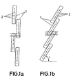
Figure 1a .- Shows the schematic arrangement of the inkjet print heads, for the printing in a single passage of the width that is required, according to a configuration in which the print width is increased maintaining the original resolution of the head. -
Figure 1b .- Is a schematic view similar to that offigure 1a , according to a configuration in which the print width and the print resolution have been increased (by a factor equal to 1/sin α). -
Figure 2a .- Shows the structure of the heads offigure 1a , repeated for each of the different inks (colours) used, ordered in different rows. -
Figure 2b .- Shows a view similar to that offigure 2a , in which the heads are repeated for each of the different inks. -
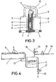
Figure 3 .- Is a schematic view in transverse cross-section of the basic structure of the self-contained inkjet printing module, in accordance with the invention. -
Figure 4 .- Is a diagram of a first system of supply of ink to the print heads, in accordance with the Invention. -
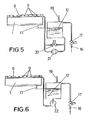
Figure 5 .- Is a diagram of a second system of supply of ink to the print heads, in accordance with the invention. -
Figure 6 .- Is a diagram of a third system of supply of ink to the print heads, in accordance with the invention. -
Figure 7 .- Shows in two positions a) and b) the print head and its closing cover in exploded view and pressed against the head, respectively, in accordance with a first solution. -
Figure 8 .- Is a view similar to that offigure 7 , in accordance with a second solution. -
Figure 9 .- Is a schematic view in longitudinal cross-section of that shown infigure 8 . -
Figure 10 .- Is a schematic view In longitudinal cross-section similar tofigure 3 but including the protection and cleaning covers for the heads, along with their actuation system, in the rest position. -
Figure 11 .- Shows in three positions a), b) and c) the sequence of movements for passing from the rest/cleaning phase offigure 10 to that of work or printing. - Making reference to the numbering adopted in the figures, and especially in relation to
figures 1a and 1b , it can be seen schematicallydifferent injector plates 1 arranged in two different ways for printing in each passage a width greater than that occupied by the injectors, with some overlapping zones being left in such a way that theinjectors 2 can perform a uniform sweeping. Infigure 1a , the original resolution is maintained and infigure 1b the resolution is increased since the lines of sweeping are closer to each other, specifically according to a factor corresponding to 1/sin α. - In
figures 2a and 2b , the repetition of these same structures offigures 1a and 1b can be seen for each of the colors of ink used, four in the case shown. - In
figure 3 can be seen the basic structure of the printing module, referenced in general with thenumber 3 and materialized by the extruded or machined metal inverted T-section profile 4, provided with windows for fitting the print heads 5 with theirinjector plates 1. -
Reference 6 designates two of the three horizontal longitudinal perforations, the lowest ones, which are connected together with the step 7 at one end, for the circulation of liquid at the desired temperature. The remaining perforation, referenced with 8 and covered by the other end, acts as a distributor and is traversed by the ink at the temperature of the block, exiting viavertical ducts 9 to therespective print heads 5 passing through thevalves 10 andtubes 11. - With special reference to
figure 4 , the ink is supplied to theheads 5 at the correct pressure, from thereservoir 12 in which the level is kept at acertain height 13 with respect to theinjector plates 1, arriving at thedistributor 8. Thereference 14 designates the entrance of air at a pressure controlled by the electrovalve 15 and thereference 16 is the entrance of Ink under pressure when theelectrovalve 17 is open. During the printing phase, theelectrovalves electrovalve 18 is open, which connects to theoutside line 19. The pressure with which the ink arrives at the heads via the distributor depends solely on the level In thereservoir 12. - In order to refill the
reservoir 12 and keep its level within the limits specified by the manufacturer of the heads, theelectrovalves electrovalves - In the second system, schematically represented in
figure 5 , ink under pressure arrives at thereservoir 12 from theduct 16 via theelectrovalve 17. Theelectrovalve 20 is fitted in bypass with theperistaltic pump 21. During the printing phase theelectrovalve 17 remains closed, theelectrovalve 2 is open and theperistaltic pump 21 is shut off. The pressure of the ink in the heads depends solely on the level inside the workingreservoir 12. - During the refilling operation, the
electrovalve 17 is open so that the ink can flow inside the reservoir without affecting the pressure of the ink in the heads due to theconnection duct 19 for the reservoir with the atmosphere. - When the pressure is increased in order to carry out the draining and priming, the
electrovalve 20 is closed and theperistaltic pump 21 is started up, with the ink flowing through the injector orifices. - In relation to
figure 6 where the third system of supplying ink to the print heads is shown, theelectrovalve 17 remains closed and thecentrifugal pump 22 is shut off, in such a way that the pressure of the ink in the heads depends only on thelevel 13 inside the workingreservoir 12. In this system, the ink flows via the ducts of the impeller of the centrifugal pump which is shut off. - For the refilling, the
electrovalve 17 is opened so that the ink flows inside thereservoir 12 since it is connected to the outside via theduct 19. - When it is required to increase the pressure in order to carry out draining and priming, the
centrifugal pump 22 is started up. This system also allows refilling simultaneous with draining. - In
figure 7 , positions a) and b), theprint head 5 can be seen protected by theflaps 23 leaving just thesmall groove 24 exposed. Between the lower face of theinjector plate 1 and theflaps 23 is arranged theabsorbent sponge 25. - The
reference 26 designates the concave cover with anotherabsorbent sponge 27 which collects the surplus ink. During the cleaning process, thecover 26 moves to position b) offigure 7 and after the draining the surplus ink is sucked up via theduct 28, and at the same time the air is sucked through theslits 29 dries theabsorbent lamina 25. Themound 30 formed when thesponge 27 presses on thegroove 24 helps to eliminate drops from theinjector plate 1. - In the second solution, according to that shown squematically in
figures 8 and9 , the injector plate is entirely exposed due to theprint head 5 being mounted on the window made in the support orprofile 4. - Now, the
concave cover 26 has twoabsorbent sponges 31 housed in the ends of its cavity, which are for collecting the surplus ink, and also for cleaning the spatula referenced with 32 at the end of each travel. During the cleaning process, the cover goes to its position and following the draining the surplus ink is sucked through theduct 28. Thespatula 32 then collects the drops remaining on the injector plate in a longitudinal movement, depositing them on thesponges 31 at the end. As can be seen, thespatula 32 can oscillate freely on thecylinder 33 in which it is fitted, this cylinder being integral with therod 34 in such a way that when the latter moves, the spatula can tilt (rotating on the cylinder 33) in order to be able to slide more smoothly on the injector plate. - Having described the typologies of the cover that covers the injector plate, we are now going to see how it is installed In the printing module and how these pieces move from the rest and cleaning position to the printing position. In
figure 10 it can be seen that theheads 5 are fitted on the inverted T-section profile 4 in two parallel rows. The covers must therefore also have this configuration of two parallel rows. - In the diagram of
figure 10 the covers of each row are made of a single piece in the form of bars and are referenced withnumber 35. They include alongitudinal duct 36 which links the outlets for ink from each one. - Each of the
bars 35 is joined toseveral cranks 37 perpendicular to separatevertical shafts 38 which have the possibility of rotating, rising and falling. The different cranks 37 cause the rotation of theshafts 38 to become converted into a parallel displacement of thebars 35. Thisfigure 10 shows the system in a rest/cleaning position in which all the actions aimed at priming the injectors and cleaning the injector pate will be carried out. - In order to pass from the rest/cleaning position to the working position, the following sequence of movements is carried out as shown in
figure 11 in three positions a), b) and c). - The
vertical shafts 38 rotate in thesupports 39 and slide downwards starting from the position shown infigure 10 , as shown In position a) offigure 11 . - Next, the
vertical shafts 38 rotate through 90° displacing thebars 35 in parallel which adopt the position shown in figure position b). - When the
vertical shafts 38 slide upwards as shown in position c), the working position is acquired.
Claims (8)
- SELF-CONTAINED INKJET PRINTING MODULE, comprising print heads for printing the required width in a single passage, and a maintenance system for the installed print heads, along with a pressurisation and thermal conditioning system for the ink used, there existing as many modules as are necessary depending on the number of inks and the desired print resolution, further comprising a mechanism capable of covering an injector plate and collecting the ink poured during each draining operation, leaving said injector plate as clean as possible, moreover preventing the Ink from drying out when the module is not functioning, characterised in that it comprises an extruded or machined metal inverted T-section profile (4) on which the print heads (5) are mounted, with the injector plate (1) being left exposed via the lower part, provision having been made for the said metal profile (4) to include,along the entire length of its core, three horizontal cylindrical perforations (6, 8), the lowest ones being linked together via one end by means of a duct (7) defining a circuit for the circulation of liquid at the desired temperature, while the upper one (8) takes on functions of distributor and thermal conditioning of the ink entering through one end and passing through to the print heads (5) via vertical ducts (9) made in the upper part and by means of respective manual valves (10) and tubes (11).
- SELF-CONTAINED INKJET PRINTING MODULE, according to claim 1, characterised in that the ink is supplied to the print heads (5) with the right pressure at each moment, by means of a working reservoir (12) with a level lower than the injector plates (1), having electrovalves (15, 17) for the entrance of air under pressure (15) and of ink under pressure (17) which are closed and an electrovalve (18) that links with the outside which is open during the printing phase; the working reservoir (12) being filled in order to maintain the level as the ink is consumed, with the electrovalves for the entrance of ink under pressure (17) and the electrovalve (18) for connection with the outside remaining open.
- SELF-CONTAINED INKJET PRINTING MODULE, according to claim 1, characterised in that during the printing phase the Ink is supplied to the print heads (5) via a distributor (8), by means of a working reservoir (12) with a level lower than the injector plates (1), having an electrovalve (17) for the entrance of ink under pressure to the reservoir (12) which is closed and an electrovalve (20) for linking In bypass with a peristaltic pump (21) for feeding the distributor (8) from the reservoir (12) which is open, said peristaltic pump (21) being shut off; the working reservoir (12) being filled in order to maintain the level due to the electrovalve (17) for the entrance of ink under pressure being open and the reservoir (12) being linked to the outside by means of a duct (19).
- SELF-CONTAINED INKJET PRINTING MODULE, according to claim 1, characterised in that during the printing phase the ink is supplied to the print heads (5) via a distributor (8), by means of a working reservoir (12) with a level lower than the injector plates (1), having an electrovalve (17) for the entrance of ink under pressure to the reservoir (12) which is closed and a centrifugal pump (22) for feeding the distributor (8) which is shut off, the ink flowing via channels of the impeller thereof; the working reservoir (12) being filled in order to maintain the level by opening the electrovalve (17) for the entrance of ink and the reservoir (12) being linked to the outside by means of a duct (19).
- SELF-CONTAINED INKJET PRINTING MODULE, according to claim 1, characterised in that the print head (5) is protected by some flaps (23) which leave the injectors visible via a small groove (24) and there existing a lamina of absorbent sponge (25) between the injector plate (1) and said flaps (23), further including a movable concave cover (26) with another absorbent sponge (27) which collects the surplus ink, this surplus ink being sucked through a hole (28) in its base, the absorbent sponge (27) forming a mound (30) which closes and helps in cleaning the injectors.
- SELF-CONTAINED INKJET PRINTING MODULE, according to claim 1, characterised in that the print head (5) leaves the injector plate (1) exposed due to its positioning in a window made in the metal support or profile (4), further including a concave movable cover (26) with two absorbent sponges (31) at the ends of its cavity, which collect the surplus ink and clean a spatula (32) at the end of each travel.
- SELF-CONTAINED INKJET PRINTING MODULE, according to claim 6, characterised in that the spatula (32) is freely oscillating in a cylinder (33) perpendicularly integral to a longitudinal rod (34) so that when the latter moves axially the spatula tilt and slide more smoothly on the injector plate (1).
- SELF-CONTAINED INKJET PRINTING MODULE, according to claim 1, characterised in that concave covers (26) are arranged in two parallel rows beneath the wings of the inverted T-section profile (4), in a single piece or lateral bar (35), with a longitudinal duct (36) as collector for all the ink outlets, both bars (35) being attached to various cranks (37) parallel to each other and connected to separate vertical shafts (38) able to perform a rotary and axial movement, for the parallel displacement of both bars (35) from the rest position as far as the working position and vice versa.
Applications Claiming Priority (2)
| Application Number | Priority Date | Filing Date | Title |
|---|---|---|---|
| ES200603033A ES2302634B1 (en) | 2006-11-28 | 2006-11-28 | AUTONOMOUS PRINTING MODULE BY INK JET. |
| PCT/ES2007/000680 WO2008065222A1 (en) | 2006-11-28 | 2007-11-26 | Self-contained inkjet printing module |
Publications (3)
| Publication Number | Publication Date |
|---|---|
| EP2090439A1 true EP2090439A1 (en) | 2009-08-19 |
| EP2090439A4 EP2090439A4 (en) | 2011-06-29 |
| EP2090439B1 EP2090439B1 (en) | 2012-09-05 |
Family
ID=39467472
Family Applications (1)
| Application Number | Title | Priority Date | Filing Date |
|---|---|---|---|
| EP07858257A Not-in-force EP2090439B1 (en) | 2006-11-28 | 2007-11-26 | Self-contained inkjet printing module |
Country Status (3)
| Country | Link |
|---|---|
| EP (1) | EP2090439B1 (en) |
| ES (2) | ES2302634B1 (en) |
| WO (1) | WO2008065222A1 (en) |
Cited By (4)
| Publication number | Priority date | Publication date | Assignee | Title |
|---|---|---|---|---|
| ES2561727A1 (en) * | 2014-08-29 | 2016-02-29 | Kerajet S.A. | Device, method and machine for deposition of fluids on a surface (Machine-translation by Google Translate, not legally binding) |
| ES2558023R1 (en) * | 2014-07-29 | 2016-03-15 | Kerajet S.A. | Device, Method and Machine for fluid deposition on a surface. |
| EP2759408A4 (en) * | 2011-09-21 | 2016-10-12 | Konica Minolta Inc | Inkjet recording apparatus |
| EP3556563A1 (en) * | 2012-09-12 | 2019-10-23 | Linx Printing Technologies Ltd | Ink jet print head and cap |
Families Citing this family (1)
| Publication number | Priority date | Publication date | Assignee | Title |
|---|---|---|---|---|
| ES2472140B2 (en) | 2014-02-07 | 2015-01-29 | Kerajet S.A. | Method of projection of solids on a surface |
Family Cites Families (9)
| Publication number | Priority date | Publication date | Assignee | Title |
|---|---|---|---|---|
| US4985710A (en) * | 1989-11-29 | 1991-01-15 | Xerox Corporation | Buttable subunits for pagewidth "Roofshooter" printheads |
| US5057854A (en) * | 1990-06-26 | 1991-10-15 | Xerox Corporation | Modular partial bars and full width array printheads fabricated from modular partial bars |
| US5160945A (en) * | 1991-05-10 | 1992-11-03 | Xerox Corporation | Pagewidth thermal ink jet printhead |
| IT1272050B (en) * | 1993-11-10 | 1997-06-11 | Olivetti Canon Ind Spa | PARALLEL PRINTER DEVICE WITH MODULAR STRUCTURE AND RELATED CONSTRUCTION PROCEDURE. |
| US6135586A (en) * | 1995-10-31 | 2000-10-24 | Hewlett-Packard Company | Large area inkjet printhead |
| EP0870622A1 (en) * | 1997-04-07 | 1998-10-14 | Xerox Corporation | Ink jet printer with improved printhead cooling system |
| DE19743804A1 (en) * | 1997-10-02 | 1999-04-08 | Politrust Ag | Large format printing using ink-jet printer |
| GB0011916D0 (en) * | 2000-05-17 | 2000-07-05 | Cambridge Consultants | Printing |
| DE602004012502T2 (en) * | 2003-09-24 | 2009-06-10 | Fujifilm Corporation | Droplet ejection head and inkjet recording device |
-
2006
- 2006-11-28 ES ES200603033A patent/ES2302634B1/en not_active Expired - Fee Related
-
2007
- 2007-11-26 ES ES07858257T patent/ES2392951T3/en active Active
- 2007-11-26 EP EP07858257A patent/EP2090439B1/en not_active Not-in-force
- 2007-11-26 WO PCT/ES2007/000680 patent/WO2008065222A1/en not_active Ceased
Cited By (5)
| Publication number | Priority date | Publication date | Assignee | Title |
|---|---|---|---|---|
| EP2759408A4 (en) * | 2011-09-21 | 2016-10-12 | Konica Minolta Inc | Inkjet recording apparatus |
| EP3556563A1 (en) * | 2012-09-12 | 2019-10-23 | Linx Printing Technologies Ltd | Ink jet print head and cap |
| ES2558023R1 (en) * | 2014-07-29 | 2016-03-15 | Kerajet S.A. | Device, Method and Machine for fluid deposition on a surface. |
| ES2561727A1 (en) * | 2014-08-29 | 2016-02-29 | Kerajet S.A. | Device, method and machine for deposition of fluids on a surface (Machine-translation by Google Translate, not legally binding) |
| WO2016030566A1 (en) * | 2014-08-29 | 2016-03-03 | Kerajet, S.A. | Device, method, and machine for depositing fluids on a surface |
Also Published As
| Publication number | Publication date |
|---|---|
| ES2392951T3 (en) | 2012-12-17 |
| ES2302634B1 (en) | 2009-05-21 |
| WO2008065222A1 (en) | 2008-06-05 |
| EP2090439B1 (en) | 2012-09-05 |
| ES2302634A1 (en) | 2008-07-16 |
| EP2090439A4 (en) | 2011-06-29 |
Similar Documents
| Publication | Publication Date | Title |
|---|---|---|
| EP2090439B1 (en) | Self-contained inkjet printing module | |
| DE60309959T2 (en) | Techniques for delivering fluids with improved reliability | |
| DE69319065T2 (en) | Cleaning device with wiper blade for a color jet print head | |
| US7347540B2 (en) | Inkjet printing device | |
| CN1315653C (en) | Image recording apparatus with maintenance unit | |
| DE69404528T2 (en) | Damp wipe care device for full-width color jet printers | |
| DE69513787T2 (en) | Aeration device for dye cartridge | |
| US8746860B2 (en) | Ink supply system and process for cleaning this type of ink supply system | |
| CN102922881B (en) | Inkjet print head and ink storage apparatus | |
| US8231208B2 (en) | Liquid ejection head | |
| US5424768A (en) | Zero-volume maintenance cap for an ink jet printhead | |
| KR100314876B1 (en) | Inkjet printer | |
| DE102009020702A1 (en) | Printing system for printing on bottles or similar containers and printing device or machine with such a printing system | |
| JP5492837B2 (en) | Inkjet recording apparatus, inkjet recording method, and inkjet head cleaning apparatus | |
| JPH04273020A (en) | Printing-head mechanism for ink jet printer | |
| JPH08224897A (en) | Method of using secondary ink fountain and facsimile apparatus | |
| DE19531361C2 (en) | Leak-resistant ink tank for a printer | |
| CN111114133A (en) | Liquid ejection device and maintenance method of liquid ejection device | |
| CN103826862B (en) | inkjet printing device | |
| DE68923025T2 (en) | Interchangeable inkjet cartridge and inkjet printing device with such. | |
| CN107415476A (en) | The cleaning device and liquid injection apparatus of jet head liquid | |
| WO2025237067A1 (en) | Ink-jet head cleaning and maintenance assembly | |
| CN107297953A (en) | The clean method and liquid injection apparatus of jet head liquid | |
| DE4000416A1 (en) | Ink jet printer automated maintenance method - operating cleaning and sealing mechanism in print mechanism parking position for certain printer states | |
| JP2022021941A (en) | Cleaning device and inkjet image forming device equipped with it |
Legal Events
| Date | Code | Title | Description |
|---|---|---|---|
| PUAI | Public reference made under article 153(3) epc to a published international application that has entered the european phase |
Free format text: ORIGINAL CODE: 0009012 |
|
| 17P | Request for examination filed |
Effective date: 20090625 |
|
| AK | Designated contracting states |
Kind code of ref document: A1 Designated state(s): AT BE BG CH CY CZ DE DK EE ES FI FR GB GR HU IE IS IT LI LT LU LV MC MT NL PL PT RO SE SI SK TR |
|
| DAX | Request for extension of the european patent (deleted) | ||
| A4 | Supplementary search report drawn up and despatched |
Effective date: 20110527 |
|
| REG | Reference to a national code |
Ref country code: DE Ref legal event code: R079 Ref document number: 602007025343 Country of ref document: DE Free format text: PREVIOUS MAIN CLASS: B41J0002155000 Ipc: B41J0002145000 |
|
| GRAP | Despatch of communication of intention to grant a patent |
Free format text: ORIGINAL CODE: EPIDOSNIGR1 |
|
| RIC1 | Information provided on ipc code assigned before grant |
Ipc: B41J 2/145 20060101AFI20120229BHEP Ipc: B41J 2/175 20060101ALI20120229BHEP Ipc: B41J 2/165 20060101ALI20120229BHEP |
|
| GRAS | Grant fee paid |
Free format text: ORIGINAL CODE: EPIDOSNIGR3 |
|
| GRAA | (expected) grant |
Free format text: ORIGINAL CODE: 0009210 |
|
| AK | Designated contracting states |
Kind code of ref document: B1 Designated state(s): AT BE BG CH CY CZ DE DK EE ES FI FR GB GR HU IE IS IT LI LT LU LV MC MT NL PL PT RO SE SI SK TR |
|
| REG | Reference to a national code |
Ref country code: GB Ref legal event code: FG4D |
|
| REG | Reference to a national code |
Ref country code: CH Ref legal event code: EP |
|
| REG | Reference to a national code |
Ref country code: AT Ref legal event code: REF Ref document number: 573908 Country of ref document: AT Kind code of ref document: T Effective date: 20120915 |
|
| REG | Reference to a national code |
Ref country code: IE Ref legal event code: FG4D |
|
| REG | Reference to a national code |
Ref country code: DE Ref legal event code: R096 Ref document number: 602007025343 Country of ref document: DE Effective date: 20121031 |
|
| REG | Reference to a national code |
Ref country code: ES Ref legal event code: FG2A Ref document number: 2392951 Country of ref document: ES Kind code of ref document: T3 Effective date: 20121217 |
|
| REG | Reference to a national code |
Ref country code: AT Ref legal event code: MK05 Ref document number: 573908 Country of ref document: AT Kind code of ref document: T Effective date: 20120905 |
|
| REG | Reference to a national code |
Ref country code: NL Ref legal event code: VDEP Effective date: 20120905 |
|
| PG25 | Lapsed in a contracting state [announced via postgrant information from national office to epo] |
Ref country code: FI Free format text: LAPSE BECAUSE OF FAILURE TO SUBMIT A TRANSLATION OF THE DESCRIPTION OR TO PAY THE FEE WITHIN THE PRESCRIBED TIME-LIMIT Effective date: 20120905 Ref country code: AT Free format text: LAPSE BECAUSE OF FAILURE TO SUBMIT A TRANSLATION OF THE DESCRIPTION OR TO PAY THE FEE WITHIN THE PRESCRIBED TIME-LIMIT Effective date: 20120905 Ref country code: CY Free format text: LAPSE BECAUSE OF FAILURE TO SUBMIT A TRANSLATION OF THE DESCRIPTION OR TO PAY THE FEE WITHIN THE PRESCRIBED TIME-LIMIT Effective date: 20120905 Ref country code: LT Free format text: LAPSE BECAUSE OF FAILURE TO SUBMIT A TRANSLATION OF THE DESCRIPTION OR TO PAY THE FEE WITHIN THE PRESCRIBED TIME-LIMIT Effective date: 20120905 |
|
| REG | Reference to a national code |
Ref country code: LT Ref legal event code: MG4D Effective date: 20120905 |
|
| PG25 | Lapsed in a contracting state [announced via postgrant information from national office to epo] |
Ref country code: SI Free format text: LAPSE BECAUSE OF FAILURE TO SUBMIT A TRANSLATION OF THE DESCRIPTION OR TO PAY THE FEE WITHIN THE PRESCRIBED TIME-LIMIT Effective date: 20120905 Ref country code: SE Free format text: LAPSE BECAUSE OF FAILURE TO SUBMIT A TRANSLATION OF THE DESCRIPTION OR TO PAY THE FEE WITHIN THE PRESCRIBED TIME-LIMIT Effective date: 20120905 Ref country code: LV Free format text: LAPSE BECAUSE OF FAILURE TO SUBMIT A TRANSLATION OF THE DESCRIPTION OR TO PAY THE FEE WITHIN THE PRESCRIBED TIME-LIMIT Effective date: 20120905 Ref country code: GR Free format text: LAPSE BECAUSE OF FAILURE TO SUBMIT A TRANSLATION OF THE DESCRIPTION OR TO PAY THE FEE WITHIN THE PRESCRIBED TIME-LIMIT Effective date: 20121206 |
|
| PGFP | Annual fee paid to national office [announced via postgrant information from national office to epo] |
Ref country code: ES Payment date: 20121029 Year of fee payment: 6 Ref country code: IT Payment date: 20121129 Year of fee payment: 6 |
|
| PG25 | Lapsed in a contracting state [announced via postgrant information from national office to epo] |
Ref country code: EE Free format text: LAPSE BECAUSE OF FAILURE TO SUBMIT A TRANSLATION OF THE DESCRIPTION OR TO PAY THE FEE WITHIN THE PRESCRIBED TIME-LIMIT Effective date: 20120905 Ref country code: CZ Free format text: LAPSE BECAUSE OF FAILURE TO SUBMIT A TRANSLATION OF THE DESCRIPTION OR TO PAY THE FEE WITHIN THE PRESCRIBED TIME-LIMIT Effective date: 20120905 Ref country code: BE Free format text: LAPSE BECAUSE OF FAILURE TO SUBMIT A TRANSLATION OF THE DESCRIPTION OR TO PAY THE FEE WITHIN THE PRESCRIBED TIME-LIMIT Effective date: 20120905 Ref country code: RO Free format text: LAPSE BECAUSE OF FAILURE TO SUBMIT A TRANSLATION OF THE DESCRIPTION OR TO PAY THE FEE WITHIN THE PRESCRIBED TIME-LIMIT Effective date: 20120905 Ref country code: IS Free format text: LAPSE BECAUSE OF FAILURE TO SUBMIT A TRANSLATION OF THE DESCRIPTION OR TO PAY THE FEE WITHIN THE PRESCRIBED TIME-LIMIT Effective date: 20130105 Ref country code: NL Free format text: LAPSE BECAUSE OF FAILURE TO SUBMIT A TRANSLATION OF THE DESCRIPTION OR TO PAY THE FEE WITHIN THE PRESCRIBED TIME-LIMIT Effective date: 20120905 |
|
| PG25 | Lapsed in a contracting state [announced via postgrant information from national office to epo] |
Ref country code: PT Free format text: LAPSE BECAUSE OF FAILURE TO SUBMIT A TRANSLATION OF THE DESCRIPTION OR TO PAY THE FEE WITHIN THE PRESCRIBED TIME-LIMIT Effective date: 20130107 Ref country code: PL Free format text: LAPSE BECAUSE OF FAILURE TO SUBMIT A TRANSLATION OF THE DESCRIPTION OR TO PAY THE FEE WITHIN THE PRESCRIBED TIME-LIMIT Effective date: 20120905 Ref country code: SK Free format text: LAPSE BECAUSE OF FAILURE TO SUBMIT A TRANSLATION OF THE DESCRIPTION OR TO PAY THE FEE WITHIN THE PRESCRIBED TIME-LIMIT Effective date: 20120905 |
|
| REG | Reference to a national code |
Ref country code: CH Ref legal event code: PL |
|
| PLBE | No opposition filed within time limit |
Free format text: ORIGINAL CODE: 0009261 |
|
| STAA | Information on the status of an ep patent application or granted ep patent |
Free format text: STATUS: NO OPPOSITION FILED WITHIN TIME LIMIT |
|
| PG25 | Lapsed in a contracting state [announced via postgrant information from national office to epo] |
Ref country code: BG Free format text: LAPSE BECAUSE OF FAILURE TO SUBMIT A TRANSLATION OF THE DESCRIPTION OR TO PAY THE FEE WITHIN THE PRESCRIBED TIME-LIMIT Effective date: 20121205 Ref country code: CH Free format text: LAPSE BECAUSE OF NON-PAYMENT OF DUE FEES Effective date: 20121130 Ref country code: LI Free format text: LAPSE BECAUSE OF NON-PAYMENT OF DUE FEES Effective date: 20121130 Ref country code: DK Free format text: LAPSE BECAUSE OF FAILURE TO SUBMIT A TRANSLATION OF THE DESCRIPTION OR TO PAY THE FEE WITHIN THE PRESCRIBED TIME-LIMIT Effective date: 20120905 |
|
| 26N | No opposition filed |
Effective date: 20130606 |
|
| REG | Reference to a national code |
Ref country code: FR Ref legal event code: ST Effective date: 20130731 |
|
| GBPC | Gb: european patent ceased through non-payment of renewal fee |
Effective date: 20121205 |
|
| REG | Reference to a national code |
Ref country code: IE Ref legal event code: MM4A |
|
| REG | Reference to a national code |
Ref country code: DE Ref legal event code: R119 Ref document number: 602007025343 Country of ref document: DE Effective date: 20130601 |
|
| PG25 | Lapsed in a contracting state [announced via postgrant information from national office to epo] |
Ref country code: IE Free format text: LAPSE BECAUSE OF NON-PAYMENT OF DUE FEES Effective date: 20121126 Ref country code: DE Free format text: LAPSE BECAUSE OF NON-PAYMENT OF DUE FEES Effective date: 20130601 |
|
| PG25 | Lapsed in a contracting state [announced via postgrant information from national office to epo] |
Ref country code: FR Free format text: LAPSE BECAUSE OF NON-PAYMENT OF DUE FEES Effective date: 20121130 Ref country code: GB Free format text: LAPSE BECAUSE OF NON-PAYMENT OF DUE FEES Effective date: 20121205 Ref country code: MT Free format text: LAPSE BECAUSE OF FAILURE TO SUBMIT A TRANSLATION OF THE DESCRIPTION OR TO PAY THE FEE WITHIN THE PRESCRIBED TIME-LIMIT Effective date: 20120905 |
|
| PG25 | Lapsed in a contracting state [announced via postgrant information from national office to epo] |
Ref country code: TR Free format text: LAPSE BECAUSE OF FAILURE TO SUBMIT A TRANSLATION OF THE DESCRIPTION OR TO PAY THE FEE WITHIN THE PRESCRIBED TIME-LIMIT Effective date: 20120905 Ref country code: MC Free format text: LAPSE BECAUSE OF NON-PAYMENT OF DUE FEES Effective date: 20121130 |
|
| PG25 | Lapsed in a contracting state [announced via postgrant information from national office to epo] |
Ref country code: LU Free format text: LAPSE BECAUSE OF NON-PAYMENT OF DUE FEES Effective date: 20121126 |
|
| PG25 | Lapsed in a contracting state [announced via postgrant information from national office to epo] |
Ref country code: HU Free format text: LAPSE BECAUSE OF FAILURE TO SUBMIT A TRANSLATION OF THE DESCRIPTION OR TO PAY THE FEE WITHIN THE PRESCRIBED TIME-LIMIT Effective date: 20071126 |
|
| PG25 | Lapsed in a contracting state [announced via postgrant information from national office to epo] |
Ref country code: IT Free format text: LAPSE BECAUSE OF NON-PAYMENT OF DUE FEES Effective date: 20131126 |
|
| REG | Reference to a national code |
Ref country code: ES Ref legal event code: FD2A Effective date: 20150703 |
|
| PG25 | Lapsed in a contracting state [announced via postgrant information from national office to epo] |
Ref country code: ES Free format text: LAPSE BECAUSE OF NON-PAYMENT OF DUE FEES Effective date: 20131127 |