EP2090417A1 - Seal ring - Google Patents
Seal ring Download PDFInfo
- Publication number
- EP2090417A1 EP2090417A1 EP08002632A EP08002632A EP2090417A1 EP 2090417 A1 EP2090417 A1 EP 2090417A1 EP 08002632 A EP08002632 A EP 08002632A EP 08002632 A EP08002632 A EP 08002632A EP 2090417 A1 EP2090417 A1 EP 2090417A1
- Authority
- EP
- European Patent Office
- Prior art keywords
- seal ring
- seal
- ejector
- sealing surface
- injection
- Prior art date
- Legal status (The legal status is an assumption and is not a legal conclusion. Google has not performed a legal analysis and makes no representation as to the accuracy of the status listed.)
- Granted
Links
- 238000007789 sealing Methods 0.000 claims abstract description 13
- 230000005540 biological transmission Effects 0.000 claims abstract description 10
- 238000001746 injection moulding Methods 0.000 claims description 7
- 238000000034 method Methods 0.000 claims description 4
- 239000000463 material Substances 0.000 claims description 3
- 238000002347 injection Methods 0.000 description 4
- 239000007924 injection Substances 0.000 description 4
- 239000011324 bead Substances 0.000 description 2
- 230000008878 coupling Effects 0.000 description 1
- 238000010168 coupling process Methods 0.000 description 1
- 238000005859 coupling reaction Methods 0.000 description 1
- 239000007788 liquid Substances 0.000 description 1
- 239000002184 metal Substances 0.000 description 1
- 230000002787 reinforcement Effects 0.000 description 1
Images
Classifications
-
- F—MECHANICAL ENGINEERING; LIGHTING; HEATING; WEAPONS; BLASTING
- F16—ENGINEERING ELEMENTS AND UNITS; GENERAL MEASURES FOR PRODUCING AND MAINTAINING EFFECTIVE FUNCTIONING OF MACHINES OR INSTALLATIONS; THERMAL INSULATION IN GENERAL
- F16J—PISTONS; CYLINDERS; SEALINGS
- F16J15/00—Sealings
- F16J15/44—Free-space packings
- F16J15/441—Free-space packings with floating ring
-
- B—PERFORMING OPERATIONS; TRANSPORTING
- B29—WORKING OF PLASTICS; WORKING OF SUBSTANCES IN A PLASTIC STATE IN GENERAL
- B29C—SHAPING OR JOINING OF PLASTICS; SHAPING OF MATERIAL IN A PLASTIC STATE, NOT OTHERWISE PROVIDED FOR; AFTER-TREATMENT OF THE SHAPED PRODUCTS, e.g. REPAIRING
- B29C45/00—Injection moulding, i.e. forcing the required volume of moulding material through a nozzle into a closed mould; Apparatus therefor
- B29C45/0025—Preventing defects on the moulded article, e.g. weld lines, shrinkage marks
-
- B—PERFORMING OPERATIONS; TRANSPORTING
- B29—WORKING OF PLASTICS; WORKING OF SUBSTANCES IN A PLASTIC STATE IN GENERAL
- B29C—SHAPING OR JOINING OF PLASTICS; SHAPING OF MATERIAL IN A PLASTIC STATE, NOT OTHERWISE PROVIDED FOR; AFTER-TREATMENT OF THE SHAPED PRODUCTS, e.g. REPAIRING
- B29C45/00—Injection moulding, i.e. forcing the required volume of moulding material through a nozzle into a closed mould; Apparatus therefor
- B29C45/17—Component parts, details or accessories; Auxiliary operations
- B29C45/40—Removing or ejecting moulded articles
- B29C45/4005—Ejector constructions; Ejector operating mechanisms
-
- B—PERFORMING OPERATIONS; TRANSPORTING
- B29—WORKING OF PLASTICS; WORKING OF SUBSTANCES IN A PLASTIC STATE IN GENERAL
- B29C—SHAPING OR JOINING OF PLASTICS; SHAPING OF MATERIAL IN A PLASTIC STATE, NOT OTHERWISE PROVIDED FOR; AFTER-TREATMENT OF THE SHAPED PRODUCTS, e.g. REPAIRING
- B29C45/00—Injection moulding, i.e. forcing the required volume of moulding material through a nozzle into a closed mould; Apparatus therefor
- B29C45/17—Component parts, details or accessories; Auxiliary operations
- B29C45/40—Removing or ejecting moulded articles
- B29C2045/4063—Removing or ejecting moulded articles preventing damage to articles caused by the ejector
-
- Y—GENERAL TAGGING OF NEW TECHNOLOGICAL DEVELOPMENTS; GENERAL TAGGING OF CROSS-SECTIONAL TECHNOLOGIES SPANNING OVER SEVERAL SECTIONS OF THE IPC; TECHNICAL SUBJECTS COVERED BY FORMER USPC CROSS-REFERENCE ART COLLECTIONS [XRACs] AND DIGESTS
- Y10—TECHNICAL SUBJECTS COVERED BY FORMER USPC
- Y10T—TECHNICAL SUBJECTS COVERED BY FORMER US CLASSIFICATION
- Y10T29/00—Metal working
- Y10T29/49—Method of mechanical manufacture
- Y10T29/4998—Combined manufacture including applying or shaping of fluent material
Definitions
- the invention concerns a seal ring, especially for use in automatic transmissions.
- Seal rings are used in many technical fields. In automatic transmissions for example, seal rings are used in order to avoid hydraulic leakage between channels. As there a high pressures in the channels, imperfections of the seal rings lead to leakage between the channels.
- the document CA 2 427 972 A1 describes a bellows seal for a quick connect coupling.
- the bellows seal has a toroidal portion with a substantially planar sealing surface at one end of the toroidal portion and a bellows portion at the other end of the toroidal portion.
- the bellows portion extends away from the toroidal portion and is semicircular in cross-section and terminates in a circumferential sealing bead at an apex of the bellows portion.
- the toroidal portion may have a metal reinforcement ring.
- the termination bead of the bellows portion has a part circular cross-section with a diameter greater than that of the thickness of the bellows portion.
- the objective of the invention is to provide a seal ring which tends less to leakage than known seal rings.
- the invention is based on the consideration that it is the presence of ejector traces, especially ejector pin marks, on the sealing surface of the seal ring to which the leakage is due. These ejector traces come from the injection process in which the seal ring is produced. Ejector pins are necessary in order to get the seal ring out of the cavity of the mould after the injection-molding. As ejector pins can not be avoided, the invention proposes therefore to displace the ejector pins from the sealing surface of the seal ring and to place them elsewhere improving thereby the flatness of the sealing surface. As they are no more on the sealing surface, they do not affect any more the sealability.
- the invention provides seal rings with improved sealability and pressure stability. When used in automatic transmissions, these seal rings improve the drivability and better pressure stability during the shifting.
- the ejector pins are placed in the inner side of the seal ring.
- the ejector pins are removed from the sealing surface thereby allowing to have a flat surface without ejector pin traces or any burr on the outer side of the seal ring which is pressed against the housing in order to avoid any leakage.
- the ejector pins are placed on tabs which are placed in recess areas on the inner side of the seal ring.
- the tabs When the seal ring is out of the cavity of the mold, the tabs are cut and it may occur that burrs remain. Upon placing the tabs with the ejector pins in recess areas on the inner side of the seal ring, it is made sure that any remaining burrs are within the recess area where they do not disturb the function of the seal ring.
- the invention also provides a process for fabricating a seal ring, especially for use in automatic transmissions, by injection-molding, with the following steps:
- This process allows to obtain seal rings with a very flat sealing surface assuring good sealability.
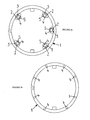
- FIGURES 1a and b schematic views of a seal ring according to the invention and a seal ring according to the prior art.
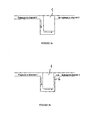
- FIGURES 2a and b schematic views of a seal ring according to the invention and a seal ring according to the prior art placed between two channels in an automatic transmission.
- FIGURES 1a and 1b the design of the seal ring in its injection-molded state is shown.
- the seal ring 1 has a plurality of recesses 2 (here eight recesses 2) regularly distributed over the inner surface of the seal ring.
- the recesses 2 have the shape of circle segments.
- a tab 3 is placed at the free end of which an ejector pin 4 is formed.
- the ejector pins 4 have a central hole 5 which allows the ejector to seize the ejector pins 4 in order to extract the hardened seal ring 1 from the mold after injection-molding thereof.
- FIGURE 1b shows a seal ring 1 according to the prior art.
- the ejector pins 4 are placed on the side of the seal ring 1.
- ejector pin marks and burrs may remain on the surface of the seal ring 1 affecting the sealability thereof.
- FIGURE 2a shows a seal ring 1 according to the invention placed between two channels (channel 1, channel 2) of an automatic transmission. It can be seen from FIGURE 2a that the seal ring 1 is pressed against the wall between channel 1 and channel 2 and thereby seals channel 1 from channel 2 with almost the whole sealing surface pressed against the wall.
- FIGURE 2b shows a seal ring 1 according to the prior art which is placed like the seal ring 1 of FIGURE 2a in order to seal a channel 1 from a channel 2.
- This seal ring 1 has an ejector trace 6 on its sealing surface (the surface which is pressed against the wall between channel 1 and channel 2). Due to this ejector trace 6, there is a leakage between channel 1 and channel 2.
Landscapes
- Engineering & Computer Science (AREA)
- Mechanical Engineering (AREA)
- General Engineering & Computer Science (AREA)
- Manufacturing & Machinery (AREA)
- Gasket Seals (AREA)
- Moulds For Moulding Plastics Or The Like (AREA)
- Sealing Devices (AREA)
- Materials For Medical Uses (AREA)
- Glass Compositions (AREA)
Abstract
Description
- The invention concerns a seal ring, especially for use in automatic transmissions.
- Seal rings are used in many technical fields. In automatic transmissions for example, seal rings are used in order to avoid hydraulic leakage between channels. As there a high pressures in the channels, imperfections of the seal rings lead to leakage between the channels.
- The
document CA 2 427 972 A1 describes a bellows seal for a quick connect coupling. The bellows seal has a toroidal portion with a substantially planar sealing surface at one end of the toroidal portion and a bellows portion at the other end of the toroidal portion. The bellows portion extends away from the toroidal portion and is semicircular in cross-section and terminates in a circumferential sealing bead at an apex of the bellows portion. The toroidal portion may have a metal reinforcement ring. The termination bead of the bellows portion has a part circular cross-section with a diameter greater than that of the thickness of the bellows portion. - It is known from
US 5,628,519 A , a seal ring having uniform dimensions over the entire length therof is described. This is achieved by properly positioning the injection point for injecting a material when injection-molding the seal ring. More specifically, the injection point is angularly displaced from the center of the entire length of the seal ring by ±1° to ±30°. - The objective of the invention is to provide a seal ring which tends less to leakage than known seal rings.
- This objective is attained according to the invention in that the seal ring is free from ejector pin traces on the sealing surface.
- The invention is based on the consideration that it is the presence of ejector traces, especially ejector pin marks, on the sealing surface of the seal ring to which the leakage is due. These ejector traces come from the injection process in which the seal ring is produced. Ejector pins are necessary in order to get the seal ring out of the cavity of the mould after the injection-molding. As ejector pins can not be avoided, the invention proposes therefore to displace the ejector pins from the sealing surface of the seal ring and to place them elsewhere improving thereby the flatness of the sealing surface. As they are no more on the sealing surface, they do not affect any more the sealability.
- The invention provides seal rings with improved sealability and pressure stability. When used in automatic transmissions, these seal rings improve the drivability and better pressure stability during the shifting.
- According to a preferred embodiment of the invention, the ejector pins are placed in the inner side of the seal ring.
- The ejector pins are removed from the sealing surface thereby allowing to have a flat surface without ejector pin traces or any burr on the outer side of the seal ring which is pressed against the housing in order to avoid any leakage.
- In a preferred embodiment of the invention, the ejector pins are placed on tabs which are placed in recess areas on the inner side of the seal ring.
- When the seal ring is out of the cavity of the mold, the tabs are cut and it may occur that burrs remain. Upon placing the tabs with the ejector pins in recess areas on the inner side of the seal ring, it is made sure that any remaining burrs are within the recess area where they do not disturb the function of the seal ring.
- The invention also provides a process for fabricating a seal ring, especially for use in automatic transmissions, by injection-molding, with the following steps:
- ● Providing a mold for a seal ring with a plurality of recesses in the inner side of the seal ring, in each recess a tab with an ejector pin being placed,
- ● Injecting a material into the mold thereby injection-molding a seal ring,
- ● When the seal ring is hardened, seizing the seal ring on the ejector pins and extracting the seal ring from the mold,
- ● Cutting the tabs close to the wall of the inner side of the seal ring.
- This process allows to obtain seal rings with a very flat sealing surface assuring good sealability.
- The invention is hereafter explained in detail with reference to the drawings which represent
-
FIGURES 1a and b schematic views of a seal ring according to the invention and a seal ring according to the prior art. -
FIGURES 2a and b schematic views of a seal ring according to the invention and a seal ring according to the prior art placed between two channels in an automatic transmission. - In
FIGURES 1a and 1b , the design of the seal ring in its injection-molded state is shown. It can be seen fromFIGURE 1a , that theseal ring 1 has a plurality of recesses 2 (here eight recesses 2) regularly distributed over the inner surface of the seal ring. Therecesses 2 have the shape of circle segments. In the middle of eachrecess 2, atab 3 is placed at the free end of which anejector pin 4 is formed. Theejector pins 4 have acentral hole 5 which allows the ejector to seize theejector pins 4 in order to extract the hardenedseal ring 1 from the mold after injection-molding thereof. -
FIGURE 1b shows aseal ring 1 according to the prior art. On thisseal ring 1, theejector pins 4 are placed on the side of theseal ring 1. When they are cut after having used for seizing theseal ring 1 in order to extract it from the injection mold, ejector pin marks and burrs may remain on the surface of theseal ring 1 affecting the sealability thereof. -
FIGURE 2a shows aseal ring 1 according to the invention placed between two channels (channel 1, channel 2) of an automatic transmission. It can be seen fromFIGURE 2a that theseal ring 1 is pressed against the wall betweenchannel 1 andchannel 2 and thereby sealschannel 1 fromchannel 2 with almost the whole sealing surface pressed against the wall. - Even if the hydraulic liquid in
channel 1 is under high pressure, theseal ring 1 assures a good sealability. -
FIGURE 2b shows aseal ring 1 according to the prior art which is placed like theseal ring 1 ofFIGURE 2a in order to seal achannel 1 from achannel 2. Thisseal ring 1 has anejector trace 6 on its sealing surface (the surface which is pressed against the wall betweenchannel 1 and channel 2). Due to thisejector trace 6, there is a leakage betweenchannel 1 andchannel 2.
Claims (4)
- A seal ring, especially for use in automatic transmissions, characterized in that the seal ring (1) is free from ejector pin traces on the sealing surface.
- The seal ring of claim 1, wherein the ejector pins (4) are placed in the inner side of the seal ring (1).
- The seal ring of claim 2, wherein the ejector pins (4) are placed on tabs (3) which are placed in recess areas (2) on the inner side of the seal ring (1).
- Process for fabricating a seal ring, especially for use in automatic transmissions, by injection-molding, with the following steps:● Providing a mold for a seal ring (1) with a plurality of recesses (2) in the inner side of the seal ring (1), in each recess (2) a tab (3) with an ejector pin (4) being placed,● Injecting a material into the mold thereby injection-molding a seal ring (1),● When the seal ring (1) is hardened, seizing the seal ring on the ejector pins (4) and extracting the seal ring (1) from the mold,● Cutting the tabs (3) close to the wall of the inner side of the seal ring (1).
Priority Applications (6)
| Application Number | Priority Date | Filing Date | Title |
|---|---|---|---|
| EP08002632A EP2090417B1 (en) | 2008-02-13 | 2008-02-13 | Seal ring |
| AT08002632T ATE507953T1 (en) | 2008-02-13 | 2008-02-13 | SEAL RING |
| DE602008006665T DE602008006665D1 (en) | 2008-02-13 | 2008-02-13 | sealing ring |
| US12/370,498 US20090212502A1 (en) | 2008-02-13 | 2009-02-12 | Seal ring |
| RU2009104923/06A RU2478855C2 (en) | 2008-02-13 | 2009-02-12 | Seal ring and method of its fabrication |
| CN200910130751.4A CN101520090B (en) | 2008-02-13 | 2009-02-13 | Seal ring |
Applications Claiming Priority (1)
| Application Number | Priority Date | Filing Date | Title |
|---|---|---|---|
| EP08002632A EP2090417B1 (en) | 2008-02-13 | 2008-02-13 | Seal ring |
Publications (2)
| Publication Number | Publication Date |
|---|---|
| EP2090417A1 true EP2090417A1 (en) | 2009-08-19 |
| EP2090417B1 EP2090417B1 (en) | 2011-05-04 |
Family
ID=39535649
Family Applications (1)
| Application Number | Title | Priority Date | Filing Date |
|---|---|---|---|
| EP08002632A Not-in-force EP2090417B1 (en) | 2008-02-13 | 2008-02-13 | Seal ring |
Country Status (6)
| Country | Link |
|---|---|
| US (1) | US20090212502A1 (en) |
| EP (1) | EP2090417B1 (en) |
| CN (1) | CN101520090B (en) |
| AT (1) | ATE507953T1 (en) |
| DE (1) | DE602008006665D1 (en) |
| RU (1) | RU2478855C2 (en) |
Families Citing this family (5)
| Publication number | Priority date | Publication date | Assignee | Title |
|---|---|---|---|---|
| AT514828B1 (en) * | 2013-09-24 | 2015-06-15 | Hoerbiger Kompressortech Hold | Method and mold for the production of sealing plates by injection molding as well as correspondingly produced sealing plates |
| CN103697165A (en) * | 2013-12-23 | 2014-04-02 | 陈焕祥 | Adjustable sealing oil cup of heat pump oil groove |
| CN105014080B (en) * | 2015-08-07 | 2017-08-29 | 黄若 | The design and production method of powder injection forming piston ring |
| KR102294233B1 (en) | 2017-01-10 | 2021-08-30 | 생-고뱅 퍼포먼스 플라스틱스 엘+에스 게엠베하 | Sealing ring and manufacturing method thereof |
| US10690248B2 (en) | 2017-01-10 | 2020-06-23 | Saint-Gobain Performance Plastics L+S GMBH | Injection molded seal rings and methods for making them |
Citations (5)
| Publication number | Priority date | Publication date | Assignee | Title |
|---|---|---|---|---|
| JPS63237922A (en) * | 1987-03-26 | 1988-10-04 | Saitou Plast Kogyosho:Kk | Molding method for resin product |
| US5628519A (en) | 1994-12-28 | 1997-05-13 | Ntn Corporation | Oil seal ring of synthetic resin having angularly displaced injection point |
| CA2427972A1 (en) | 2000-11-09 | 2002-05-16 | Dixon Minsup Pty Ltd | An improved seal |
| US6562272B1 (en) * | 2000-12-05 | 2003-05-13 | Cypress Semiconductor Corporation | Apparatus and method for delamination-resistant, array type molding of increased mold cap size laminate packages |
| US20040251634A1 (en) * | 2003-05-29 | 2004-12-16 | Eiichirou Shimazu | Resin seal ring and manufacturing method |
Family Cites Families (14)
| Publication number | Priority date | Publication date | Assignee | Title |
|---|---|---|---|---|
| US3214182A (en) * | 1962-02-27 | 1965-10-26 | Henry J Herbruggen | Packing ring |
| US3746348A (en) * | 1971-01-15 | 1973-07-17 | Parker Hannifin Corp | Sealing ring with retaining means |
| US4193481A (en) * | 1978-07-25 | 1980-03-18 | General Motors Corporation | Drag free sliding caliper disc brake bushing |
| US4458717A (en) * | 1983-03-14 | 1984-07-10 | Aeroquip Corporation | Cylinder cushion seal |
| DE3676251D1 (en) * | 1985-08-30 | 1991-01-31 | Mitsubishi Electric Corp | SEALING DEVICE FOR STIRLING ENGINE. |
| SU1323809A1 (en) * | 1986-02-10 | 1987-07-15 | Всесоюзный научно-исследовательский и конструкторско-технологический институт компрессорного машиностроения | Annular contact sealing |
| SU1315700A2 (en) * | 1986-03-07 | 1987-06-07 | Всесоюзный научно-исследовательский и конструкторско-технологический институт компрессорного машиностроения | Ring contact seal |
| SU1499030A1 (en) * | 1986-12-30 | 1989-08-07 | Научно-Производственное Объединение "Техэнергохимпром" | Piston seal |
| US4921258A (en) * | 1988-08-08 | 1990-05-01 | Aeroquip Corporation | Adapter seal |
| JPH0896179A (en) * | 1994-09-28 | 1996-04-12 | Toshiba Corp | Automatic ticket gate |
| JPH11508671A (en) * | 1995-06-27 | 1999-07-27 | カルシ・エンジニアリング・インコーポレーテッド | Fluid rotary shaft seals resistant to distortion and torsion |
| DE102004014867A1 (en) * | 2003-08-18 | 2005-11-24 | Continental Teves Ag & Co. Ohg | Cylinders, in particular for hydraulic motor vehicle brake systems |
| JP4645097B2 (en) * | 2003-12-01 | 2011-03-09 | 株式会社アドヴィックス | Master cylinder |
| DE102006040487B3 (en) * | 2006-08-30 | 2007-11-08 | Lucas Automotive Gmbh | Sealing ring for piston in brake cylinder fits into annular groove in cylinder wall and has sealing lip on its back of the ring which fits against piston, spacer nearer outside edge of ring projecting beyond it |
-
2008
- 2008-02-13 AT AT08002632T patent/ATE507953T1/en not_active IP Right Cessation
- 2008-02-13 EP EP08002632A patent/EP2090417B1/en not_active Not-in-force
- 2008-02-13 DE DE602008006665T patent/DE602008006665D1/en active Active
-
2009
- 2009-02-12 RU RU2009104923/06A patent/RU2478855C2/en not_active IP Right Cessation
- 2009-02-12 US US12/370,498 patent/US20090212502A1/en not_active Abandoned
- 2009-02-13 CN CN200910130751.4A patent/CN101520090B/en not_active Expired - Fee Related
Patent Citations (5)
| Publication number | Priority date | Publication date | Assignee | Title |
|---|---|---|---|---|
| JPS63237922A (en) * | 1987-03-26 | 1988-10-04 | Saitou Plast Kogyosho:Kk | Molding method for resin product |
| US5628519A (en) | 1994-12-28 | 1997-05-13 | Ntn Corporation | Oil seal ring of synthetic resin having angularly displaced injection point |
| CA2427972A1 (en) | 2000-11-09 | 2002-05-16 | Dixon Minsup Pty Ltd | An improved seal |
| US6562272B1 (en) * | 2000-12-05 | 2003-05-13 | Cypress Semiconductor Corporation | Apparatus and method for delamination-resistant, array type molding of increased mold cap size laminate packages |
| US20040251634A1 (en) * | 2003-05-29 | 2004-12-16 | Eiichirou Shimazu | Resin seal ring and manufacturing method |
Also Published As
| Publication number | Publication date |
|---|---|
| CN101520090A (en) | 2009-09-02 |
| DE602008006665D1 (en) | 2011-06-16 |
| RU2009104923A (en) | 2010-08-20 |
| EP2090417B1 (en) | 2011-05-04 |
| US20090212502A1 (en) | 2009-08-27 |
| RU2478855C2 (en) | 2013-04-10 |
| ATE507953T1 (en) | 2011-05-15 |
| CN101520090B (en) | 2013-10-30 |
Similar Documents
| Publication | Publication Date | Title |
|---|---|---|
| EP2090417A1 (en) | Seal ring | |
| US11298858B2 (en) | Method for manufacturing sealing device, and sealing device | |
| US20150137015A1 (en) | Connector for microfluidic device, a method for injecting fluid into microfluidic device using the connector and a method of providing and operating a valve | |
| JP6707614B2 (en) | Seal ring and method for manufacturing seal ring | |
| KR101301844B1 (en) | A Hose Forming Metalic Mould AND Making Method of Mandel | |
| US10641396B2 (en) | Seal ring and sealing structure | |
| CN113090836A (en) | Quick dismounting device for water-gas pipeline | |
| JP2016097645A (en) | Roller member manufacturing method, roller member mold, roller shaft, and roller member | |
| CN106103034A (en) | Manufacturing method and manufacturing apparatus of hollow member with branch | |
| CN107107417B (en) | Molding method of molding and molding die | |
| JP2010076280A (en) | Method for manufacturing branch hose | |
| JP2010110774A (en) | Vacuum casting system | |
| JP2009191920A (en) | Seal ring and method for manufacturing seal ring | |
| US20120223488A1 (en) | Sealing material on hydraulic flange | |
| US11933401B2 (en) | Plunger, instrument, and mold | |
| EP2484942B1 (en) | Seal device | |
| JP6411035B2 (en) | Method for manufacturing rotary shaft seal | |
| US20110296895A1 (en) | Manufacturing method for nozzle vane | |
| JP7153161B2 (en) | Seal rings and hydraulics | |
| JP2006007684A (en) | Synthetic resin piston | |
| JP2006347032A (en) | Mold and molding method for oil seal ring | |
| CN110831645A (en) | Gasket for syringe | |
| JP2025102353A (en) | Deburring tool and method for removing burrs from connected molded products | |
| CN120322322A (en) | Method for producing resin molded product, injection mold and resin molded product | |
| JP6288185B2 (en) | Sealing device |
Legal Events
| Date | Code | Title | Description |
|---|---|---|---|
| PUAI | Public reference made under article 153(3) epc to a published international application that has entered the european phase |
Free format text: ORIGINAL CODE: 0009012 |
|
| AK | Designated contracting states |
Kind code of ref document: A1 Designated state(s): AT BE BG CH CY CZ DE DK EE ES FI FR GB GR HR HU IE IS IT LI LT LU LV MC MT NL NO PL PT RO SE SI SK TR |
|
| AX | Request for extension of the european patent |
Extension state: AL BA MK RS |
|
| 17P | Request for examination filed |
Effective date: 20100219 |
|
| 17Q | First examination report despatched |
Effective date: 20100317 |
|
| AKX | Designation fees paid |
Designated state(s): AT BE BG CH CY CZ DE DK EE ES FI FR GB GR HR HU IE IS IT LI LT LU LV MC MT NL NO PL PT RO SE SI SK TR |
|
| GRAP | Despatch of communication of intention to grant a patent |
Free format text: ORIGINAL CODE: EPIDOSNIGR1 |
|
| GRAS | Grant fee paid |
Free format text: ORIGINAL CODE: EPIDOSNIGR3 |
|
| GRAA | (expected) grant |
Free format text: ORIGINAL CODE: 0009210 |
|
| AK | Designated contracting states |
Kind code of ref document: B1 Designated state(s): AT BE BG CH CY CZ DE DK EE ES FI FR GB GR HR HU IE IS IT LI LT LU LV MC MT NL NO PL PT RO SE SI SK TR |
|
| REG | Reference to a national code |
Ref country code: GB Ref legal event code: FG4D |
|
| REG | Reference to a national code |
Ref country code: CH Ref legal event code: EP |
|
| REG | Reference to a national code |
Ref country code: IE Ref legal event code: FG4D |
|
| REF | Corresponds to: |
Ref document number: 602008006665 Country of ref document: DE Date of ref document: 20110616 Kind code of ref document: P |
|
| REG | Reference to a national code |
Ref country code: DE Ref legal event code: R096 Ref document number: 602008006665 Country of ref document: DE Effective date: 20110616 |
|
| REG | Reference to a national code |
Ref country code: CH Ref legal event code: PFA Owner name: GM GLOBAL TECHNOLOGY OPERATIONS LLC Free format text: GM GLOBAL TECHNOLOGY OPERATIONS, INC.#300 RENAISSANCE CENTER#DETROIT MI 48265-3 (US) -TRANSFER TO- GM GLOBAL TECHNOLOGY OPERATIONS LLC#300 RENAISSANCE CENTER#DETROIT, MI 48265-3000 (US) |
|
| RAP2 | Party data changed (patent owner data changed or rights of a patent transferred) |
Owner name: GM GLOBAL TECHNOLOGY OPERATIONS LLC |
|
| REG | Reference to a national code |
Ref country code: NL Ref legal event code: VDEP Effective date: 20110504 |
|
| PG25 | Lapsed in a contracting state [announced via postgrant information from national office to epo] |
Ref country code: SE Free format text: LAPSE BECAUSE OF FAILURE TO SUBMIT A TRANSLATION OF THE DESCRIPTION OR TO PAY THE FEE WITHIN THE PRESCRIBED TIME-LIMIT Effective date: 20110504 Ref country code: NO Free format text: LAPSE BECAUSE OF FAILURE TO SUBMIT A TRANSLATION OF THE DESCRIPTION OR TO PAY THE FEE WITHIN THE PRESCRIBED TIME-LIMIT Effective date: 20110804 Ref country code: LT Free format text: LAPSE BECAUSE OF FAILURE TO SUBMIT A TRANSLATION OF THE DESCRIPTION OR TO PAY THE FEE WITHIN THE PRESCRIBED TIME-LIMIT Effective date: 20110504 Ref country code: PT Free format text: LAPSE BECAUSE OF FAILURE TO SUBMIT A TRANSLATION OF THE DESCRIPTION OR TO PAY THE FEE WITHIN THE PRESCRIBED TIME-LIMIT Effective date: 20110905 |
|
| PG25 | Lapsed in a contracting state [announced via postgrant information from national office to epo] |
Ref country code: BE Free format text: LAPSE BECAUSE OF FAILURE TO SUBMIT A TRANSLATION OF THE DESCRIPTION OR TO PAY THE FEE WITHIN THE PRESCRIBED TIME-LIMIT Effective date: 20110504 Ref country code: LV Free format text: LAPSE BECAUSE OF FAILURE TO SUBMIT A TRANSLATION OF THE DESCRIPTION OR TO PAY THE FEE WITHIN THE PRESCRIBED TIME-LIMIT Effective date: 20110504 Ref country code: AT Free format text: LAPSE BECAUSE OF FAILURE TO SUBMIT A TRANSLATION OF THE DESCRIPTION OR TO PAY THE FEE WITHIN THE PRESCRIBED TIME-LIMIT Effective date: 20110504 Ref country code: CY Free format text: LAPSE BECAUSE OF FAILURE TO SUBMIT A TRANSLATION OF THE DESCRIPTION OR TO PAY THE FEE WITHIN THE PRESCRIBED TIME-LIMIT Effective date: 20110504 Ref country code: FI Free format text: LAPSE BECAUSE OF FAILURE TO SUBMIT A TRANSLATION OF THE DESCRIPTION OR TO PAY THE FEE WITHIN THE PRESCRIBED TIME-LIMIT Effective date: 20110504 Ref country code: SI Free format text: LAPSE BECAUSE OF FAILURE TO SUBMIT A TRANSLATION OF THE DESCRIPTION OR TO PAY THE FEE WITHIN THE PRESCRIBED TIME-LIMIT Effective date: 20110504 Ref country code: ES Free format text: LAPSE BECAUSE OF FAILURE TO SUBMIT A TRANSLATION OF THE DESCRIPTION OR TO PAY THE FEE WITHIN THE PRESCRIBED TIME-LIMIT Effective date: 20110815 Ref country code: IS Free format text: LAPSE BECAUSE OF FAILURE TO SUBMIT A TRANSLATION OF THE DESCRIPTION OR TO PAY THE FEE WITHIN THE PRESCRIBED TIME-LIMIT Effective date: 20110904 Ref country code: GR Free format text: LAPSE BECAUSE OF FAILURE TO SUBMIT A TRANSLATION OF THE DESCRIPTION OR TO PAY THE FEE WITHIN THE PRESCRIBED TIME-LIMIT Effective date: 20110805 |
|
| PG25 | Lapsed in a contracting state [announced via postgrant information from national office to epo] |
Ref country code: NL Free format text: LAPSE BECAUSE OF FAILURE TO SUBMIT A TRANSLATION OF THE DESCRIPTION OR TO PAY THE FEE WITHIN THE PRESCRIBED TIME-LIMIT Effective date: 20110504 |
|
| PG25 | Lapsed in a contracting state [announced via postgrant information from national office to epo] |
Ref country code: EE Free format text: LAPSE BECAUSE OF FAILURE TO SUBMIT A TRANSLATION OF THE DESCRIPTION OR TO PAY THE FEE WITHIN THE PRESCRIBED TIME-LIMIT Effective date: 20110504 Ref country code: CZ Free format text: LAPSE BECAUSE OF FAILURE TO SUBMIT A TRANSLATION OF THE DESCRIPTION OR TO PAY THE FEE WITHIN THE PRESCRIBED TIME-LIMIT Effective date: 20110504 Ref country code: HR Free format text: LAPSE BECAUSE OF FAILURE TO SUBMIT A TRANSLATION OF THE DESCRIPTION OR TO PAY THE FEE WITHIN THE PRESCRIBED TIME-LIMIT Effective date: 20110727 |
|
| PG25 | Lapsed in a contracting state [announced via postgrant information from national office to epo] |
Ref country code: SK Free format text: LAPSE BECAUSE OF FAILURE TO SUBMIT A TRANSLATION OF THE DESCRIPTION OR TO PAY THE FEE WITHIN THE PRESCRIBED TIME-LIMIT Effective date: 20110504 Ref country code: PL Free format text: LAPSE BECAUSE OF FAILURE TO SUBMIT A TRANSLATION OF THE DESCRIPTION OR TO PAY THE FEE WITHIN THE PRESCRIBED TIME-LIMIT Effective date: 20110504 Ref country code: RO Free format text: LAPSE BECAUSE OF FAILURE TO SUBMIT A TRANSLATION OF THE DESCRIPTION OR TO PAY THE FEE WITHIN THE PRESCRIBED TIME-LIMIT Effective date: 20110504 Ref country code: DK Free format text: LAPSE BECAUSE OF FAILURE TO SUBMIT A TRANSLATION OF THE DESCRIPTION OR TO PAY THE FEE WITHIN THE PRESCRIBED TIME-LIMIT Effective date: 20110504 |
|
| PLBE | No opposition filed within time limit |
Free format text: ORIGINAL CODE: 0009261 |
|
| STAA | Information on the status of an ep patent application or granted ep patent |
Free format text: STATUS: NO OPPOSITION FILED WITHIN TIME LIMIT |
|
| 26N | No opposition filed |
Effective date: 20120207 |
|
| PG25 | Lapsed in a contracting state [announced via postgrant information from national office to epo] |
Ref country code: IT Free format text: LAPSE BECAUSE OF FAILURE TO SUBMIT A TRANSLATION OF THE DESCRIPTION OR TO PAY THE FEE WITHIN THE PRESCRIBED TIME-LIMIT Effective date: 20110504 |
|
| REG | Reference to a national code |
Ref country code: DE Ref legal event code: R097 Ref document number: 602008006665 Country of ref document: DE Effective date: 20120207 |
|
| PG25 | Lapsed in a contracting state [announced via postgrant information from national office to epo] |
Ref country code: MC Free format text: LAPSE BECAUSE OF NON-PAYMENT OF DUE FEES Effective date: 20120229 |
|
| REG | Reference to a national code |
Ref country code: CH Ref legal event code: PL |
|
| PG25 | Lapsed in a contracting state [announced via postgrant information from national office to epo] |
Ref country code: CH Free format text: LAPSE BECAUSE OF NON-PAYMENT OF DUE FEES Effective date: 20120229 Ref country code: LI Free format text: LAPSE BECAUSE OF NON-PAYMENT OF DUE FEES Effective date: 20120229 |
|
| REG | Reference to a national code |
Ref country code: IE Ref legal event code: MM4A |
|
| PG25 | Lapsed in a contracting state [announced via postgrant information from national office to epo] |
Ref country code: IE Free format text: LAPSE BECAUSE OF NON-PAYMENT OF DUE FEES Effective date: 20120213 |
|
| PG25 | Lapsed in a contracting state [announced via postgrant information from national office to epo] |
Ref country code: BG Free format text: LAPSE BECAUSE OF FAILURE TO SUBMIT A TRANSLATION OF THE DESCRIPTION OR TO PAY THE FEE WITHIN THE PRESCRIBED TIME-LIMIT Effective date: 20110804 |
|
| PG25 | Lapsed in a contracting state [announced via postgrant information from national office to epo] |
Ref country code: MT Free format text: LAPSE BECAUSE OF FAILURE TO SUBMIT A TRANSLATION OF THE DESCRIPTION OR TO PAY THE FEE WITHIN THE PRESCRIBED TIME-LIMIT Effective date: 20110504 |
|
| PG25 | Lapsed in a contracting state [announced via postgrant information from national office to epo] |
Ref country code: HR Free format text: LAPSE BECAUSE OF FAILURE TO SUBMIT A TRANSLATION OF THE DESCRIPTION OR TO PAY THE FEE WITHIN THE PRESCRIBED TIME-LIMIT Effective date: 20110504 |
|
| PG25 | Lapsed in a contracting state [announced via postgrant information from national office to epo] |
Ref country code: TR Free format text: LAPSE BECAUSE OF FAILURE TO SUBMIT A TRANSLATION OF THE DESCRIPTION OR TO PAY THE FEE WITHIN THE PRESCRIBED TIME-LIMIT Effective date: 20110504 |
|
| PG25 | Lapsed in a contracting state [announced via postgrant information from national office to epo] |
Ref country code: LU Free format text: LAPSE BECAUSE OF NON-PAYMENT OF DUE FEES Effective date: 20120213 |
|
| PG25 | Lapsed in a contracting state [announced via postgrant information from national office to epo] |
Ref country code: HU Free format text: LAPSE BECAUSE OF FAILURE TO SUBMIT A TRANSLATION OF THE DESCRIPTION OR TO PAY THE FEE WITHIN THE PRESCRIBED TIME-LIMIT Effective date: 20080213 |
|
| REG | Reference to a national code |
Ref country code: FR Ref legal event code: PLFP Year of fee payment: 9 |
|
| PGFP | Annual fee paid to national office [announced via postgrant information from national office to epo] |
Ref country code: DE Payment date: 20160209 Year of fee payment: 9 |
|
| PGFP | Annual fee paid to national office [announced via postgrant information from national office to epo] |
Ref country code: GB Payment date: 20160210 Year of fee payment: 9 Ref country code: FR Payment date: 20160108 Year of fee payment: 9 |
|
| REG | Reference to a national code |
Ref country code: DE Ref legal event code: R119 Ref document number: 602008006665 Country of ref document: DE |
|
| GBPC | Gb: european patent ceased through non-payment of renewal fee |
Effective date: 20170213 |
|
| REG | Reference to a national code |
Ref country code: FR Ref legal event code: ST Effective date: 20171031 |
|
| PG25 | Lapsed in a contracting state [announced via postgrant information from national office to epo] |
Ref country code: FR Free format text: LAPSE BECAUSE OF NON-PAYMENT OF DUE FEES Effective date: 20170228 Ref country code: DE Free format text: LAPSE BECAUSE OF NON-PAYMENT OF DUE FEES Effective date: 20170901 |
|
| PG25 | Lapsed in a contracting state [announced via postgrant information from national office to epo] |
Ref country code: GB Free format text: LAPSE BECAUSE OF NON-PAYMENT OF DUE FEES Effective date: 20170213 |