EP2090327A1 - Headgear and process for producing the same - Google Patents
Headgear and process for producing the same Download PDFInfo
- Publication number
- EP2090327A1 EP2090327A1 EP07830238A EP07830238A EP2090327A1 EP 2090327 A1 EP2090327 A1 EP 2090327A1 EP 07830238 A EP07830238 A EP 07830238A EP 07830238 A EP07830238 A EP 07830238A EP 2090327 A1 EP2090327 A1 EP 2090327A1
- Authority
- EP
- European Patent Office
- Prior art keywords
- closed curved
- headgear
- curved belt
- user
- head
- Prior art date
- Legal status (The legal status is an assumption and is not a legal conclusion. Google has not performed a legal analysis and makes no representation as to the accuracy of the status listed.)
- Granted
Links
Images




Classifications
-
- A—HUMAN NECESSITIES
- A61—MEDICAL OR VETERINARY SCIENCE; HYGIENE
- A61M—DEVICES FOR INTRODUCING MEDIA INTO, OR ONTO, THE BODY; DEVICES FOR TRANSDUCING BODY MEDIA OR FOR TAKING MEDIA FROM THE BODY; DEVICES FOR PRODUCING OR ENDING SLEEP OR STUPOR
- A61M16/00—Devices for influencing the respiratory system of patients by gas treatment, e.g. ventilators; Tracheal tubes
- A61M16/06—Respiratory or anaesthetic masks
-
- A—HUMAN NECESSITIES
- A61—MEDICAL OR VETERINARY SCIENCE; HYGIENE
- A61M—DEVICES FOR INTRODUCING MEDIA INTO, OR ONTO, THE BODY; DEVICES FOR TRANSDUCING BODY MEDIA OR FOR TAKING MEDIA FROM THE BODY; DEVICES FOR PRODUCING OR ENDING SLEEP OR STUPOR
- A61M16/00—Devices for influencing the respiratory system of patients by gas treatment, e.g. ventilators; Tracheal tubes
- A61M16/06—Respiratory or anaesthetic masks
- A61M16/0683—Holding devices therefor
-
- A—HUMAN NECESSITIES
- A62—LIFE-SAVING; FIRE-FIGHTING
- A62B—DEVICES, APPARATUS OR METHODS FOR LIFE-SAVING
- A62B18/00—Breathing masks or helmets, e.g. affording protection against chemical agents or for use at high altitudes or incorporating a pump or compressor for reducing the inhalation effort
- A62B18/08—Component parts for gas-masks or gas-helmets, e.g. windows, straps, speech transmitters, signal-devices
-
- A—HUMAN NECESSITIES
- A61—MEDICAL OR VETERINARY SCIENCE; HYGIENE
- A61M—DEVICES FOR INTRODUCING MEDIA INTO, OR ONTO, THE BODY; DEVICES FOR TRANSDUCING BODY MEDIA OR FOR TAKING MEDIA FROM THE BODY; DEVICES FOR PRODUCING OR ENDING SLEEP OR STUPOR
- A61M2207/00—Methods of manufacture, assembly or production
-
- A—HUMAN NECESSITIES
- A62—LIFE-SAVING; FIRE-FIGHTING
- A62B—DEVICES, APPARATUS OR METHODS FOR LIFE-SAVING
- A62B18/00—Breathing masks or helmets, e.g. affording protection against chemical agents or for use at high altitudes or incorporating a pump or compressor for reducing the inhalation effort
- A62B18/08—Component parts for gas-masks or gas-helmets, e.g. windows, straps, speech transmitters, signal-devices
- A62B18/084—Means for fastening gas-masks to heads or helmets
-
- Y—GENERAL TAGGING OF NEW TECHNOLOGICAL DEVELOPMENTS; GENERAL TAGGING OF CROSS-SECTIONAL TECHNOLOGIES SPANNING OVER SEVERAL SECTIONS OF THE IPC; TECHNICAL SUBJECTS COVERED BY FORMER USPC CROSS-REFERENCE ART COLLECTIONS [XRACs] AND DIGESTS
- Y10—TECHNICAL SUBJECTS COVERED BY FORMER USPC
- Y10T—TECHNICAL SUBJECTS COVERED BY FORMER US CLASSIFICATION
- Y10T29/00—Metal working
- Y10T29/49—Method of mechanical manufacture
- Y10T29/49826—Assembling or joining
Definitions
- the present invention relates to a headgear which is used for securing a respiratory mask, to the head of a user, which is used in a CPAP (Continuous Positive Airway Pressure) therapy suitable for the treatment of sleep apnea syndrome, or an NIPPV (Nasal Intermittent Positive Pressure Ventilation) therapy suitable for treatment of ventilatory insufficiency and the like and a manufacturing method for the headgear.
- CPAP Continuous Positive Airway Pressure
- NIPPV Nesal Intermittent Positive Pressure Ventilation
- Continuous Positive Airway Pressure is one of the most effective treatments for sleep apnea syndrome.
- This treatment utilizes respiratory equipment providing a positive pressure gas in the range of 400 to 2000 Pa in the nostrils, or the nostrils and the mouth, or the face of a user during sleep.
- Nasal Intermittent Positive Pressure Ventilation is one of the most effective treatments for ventilatory insufficiency, utilizing respiratory equipment providing an intermittent positive pressure gas in the range of 400 to 2400 Pa in the nostrils of a user.
- nasal masks providing a positive pressure gas in the nostrils under pressure
- full-face masks providing the positive pressure gas holding the nostrils and the mouth
- total face masks providing the positive pressure gas over the entire face.
- These respiratory masks are secure to the head of a user by a strap portion connected to a head mount of a headgear worn in the proximity of the opistocranion of the head of the user (JIS Z8500, ISO 7250).
- the respiratory mask is comprised of an elbow connecting a hose guiding the positive pressure gas for respiration, a frame connecting with the elbow to hold a mask cushion in a specified position, and a hollow mask cushion which is closely attached to the face of a user.
- a respiratory mask is closely attached to the face of a user by the tension of the stretchable strap portion of the headgear (for example, see Patent Document 1, Patent Document 2, and Patent Document 3).
- the respiratory mask is normally installed, it is known that displacement of the mask cushion occurs due to various causes while wearing. Because of that, measures have been taken which prevent or reduce the displacement corresponding to the respective causes.
- a bellows is provided between the frame portion and the face contact portion of the mask cushion, in the nasal respiratory masks described in Patent Document 1 and Patent Document 2 to prevent an influence on the mask cushion from the displacement of the frame portion which occurs by contact with bed clothing.
- a flexible material is used for the wall around the connection portion of the positive pressure gas supply hose in order to reduce the displacement of the frame portion caused when it is pulled by the positive pressure gas supply hose connected to the frame.
- Patent Document 2 Pamphlet of International Publication No. WO 01/097893
- Patent Document 3 Pamphlet of International Publication No. WO 98/04310
- Patent Document 4 Pamphlet of International Publication No. WO 96/17643
- the wearing of the headgear is necessary to secure the respiratory mask.
- the material used in the headgear stretches easily, when it is pressurized, the headgear stretches too much, the respiratory mask rises up, and creates leakage of the positive pressure gas.
- the members forming the headgear are stretched by the weight of the respiratory mask, and hence, the respiratory mask is displaced, thus creating the leakage of the positive pressure gas.
- the displacement of headgear and accordingly the respiratory mask may occur.
- the problems remaining unresolved before the filing of the present application and to be resolved by the present invention are to satisfy both the requirements of the prevention of leakage of the positive pressure gas arising in the headgear and alleviation of the compression sensation by the headgear.
- a headgear for securing a respiratory mask to a head of a user, wherein the respiratory mask contacts a face of the user to supply a positive pressure gas for respiration to the user
- the headgear comprising: a head mounted portion which is mounted on the occipital of the user, and a strap connecting to the head mounted portion, said head mounted portion having at least one closed curved belt, said closed curved belt having thereon at least one junction, at least one of the junctions provides the closed curved belt with a nonplanar structure adaptable to a shape of the head of the user.
- a method of manufacturing a headgear mentioned above comprising: cutting off step to cut off a member forming a closed curved belt portion from a planar material, and connecting step to connect at least one pair of a first cut end and a second cut end in the cut out member to form at least one junction, wherein, in said cutting off step, a series of members forming the closed curved belt portion are cut off from the planar material; at least one place of the portion of the series of members corresponding to the closed curved belt portion is cut off along a first cutting line, and is further cut off along a second cutting line which is in the proximity of the first cutting line and is not parallel with and does not intersect the first cutting line, to form said at least one pair of first cut end and second cut end, or, each of the members forming said closed curved belt portions having said at least one pair of first cut end and second cut end is individually cut off from one or more planar materials.
- the "head mounted portion” is the portion of the headgear that is secured to the periphery of the opistocranion of the head of a user by the tension of the strap. Namely, the head of the user is placed between the head mounted portion and the respiratory mask, and when both the head mounted portion and the mask are pressed against the head of the user by the tension of the strap, they are secured to the head of the user.
- the strap of the headgear of the present invention is secured at its one end to the head mounted portion, and can be secured at the other end to the respiratory mask.
- the headgear of the present invention for securing a respiratory mask has advantages, that even the headgear using a clothing fabric which is difficult to stretch can prevent the leakage of the positive pressure gas because it possesses a stereoscopic structure which adapts to the shape of the head of a user, and that a good wearing feel can be maintained.
- the headgear of the present invention for securing a respiratory mask possesses a stereoscopic structure which adapts to the shape of the head of a user, even when the headgear touches pillows or other bed clothing, the headgear is hardly caught thereby, and as a result, it is possible to prevent the respiratory mask from moving.
- the headgear of the present invention has a head mounted portion which is worn on the occipital of a user and a strap connected thereto.
- the material for the headgear of the present invention for example, synthetic resin, fabric and the like can be used, but the effect of the present invention is difficult to obtain in an excessively stretchable material.
- stretchable materials such as polyurethane foam, neoprene rubber, jerseys and make it difficult to stretch to some extent.
- Such a head mounted portion possesses at least one belt defined by a closed curve. If only to achieve the function of the headgear to secure a respiratory mask to the head of a user via the strap portion, the head mounted portion may be planar, but in fact, for the sake of providing air permeability to prevent sweating and weight savings and the like, it can use a closed curved belt shape in which the center portion is hollow. If one is skilled in the art, it is possible to decide the width of such a belt-like portion as needed, considering the stretchability, thickness, wearing feel, weight, cost and the like of the belt-like portion. If the width is too wide, generally, the weight and cost increase, and stretchability decreases.
- the width is too narrow, the pressure to the head is concentrated in a narrow region and wearing feel deteriorates. If it is necessary, performing optimization experimentation can determine a specific numerical value. Additionally, it is not necessary for the width of the belt-like portion to be the same over the entire circumference of the closed curve.
- the shape of such a closed curved belt has no specific limitations, but for example, it is possible to make the shapes circular, elliptical or polygonal such as isosceles triangular and rectangular such as regular polygonal, equilateral triangular or squares or analogous shapes.
- the shape of the closed curved belt is generally circular, elliptical, or regular polygonal, because the shape balance is good and it is easy to adjust the center of the closed curved belt to the opistocranion of the head of a user. Examples of the head mounted portion and the strap are typically shown in FIG. 5 . In FIG.
- (A) shows the shape of the closed curved belt being generally elliptical
- (B) shows the shape of the closed curved belt being generally rectangular
- (C) shows the shape of the closed curved belt being generally regular pentagonal
- (D) shows the shape of the closed curved belt being generally regular triangular.
- Such a closed curved belt possesses at least one junction which provides a nonplanar structure to the closed curved belt corresponding to the shape of the head of a user.
- the end parts of the member forming the closed curved belt preferably do not overlap. This is because a step which causes catching on pillows and other bed clothing is not created.
- This kind of junction can be produced by various connection methods such as stitching, thermal adhering, the use of adhesive agents, or the use of hook-loop material (known as Velcro TM ), but among them, producing by stitching is preferable from the viewpoint of manufacturability, wearability and durability. Consequently, the junction produced by stitching is explained below, but the present invention is not limited to this.
- the cut portion (including the first cut end and the second cut end in the present invention) of such a closed curved belt generally, is linear, but if the stitching does not cause displacement, and as far as a clearance gap is not created when the cut portions are stitched and the object of the present invention can be attained, other curved lines are also possible.
- the number of the stitched portions contributing to making such a nonplanar structure can be either one or plural.
- the headgear of the present invention other than the stitched portion which provides the closed curved belt with a nonplanar structure, for example, for the convenience of the manufacturing process, further possesses a stitched portion which does not contribute to making the nonplanar structure.
- a stitched portion which does not contribute to making the nonplanar structure.
- four stitched portions are provided wherein, every other two portions are used to make the nonplanar structure, and the other two portions do not contribute to making the nonplanar structure.
- the presence of four stitched portions is suitable for manufacturing the headgear of a four strap structure which when worn has an especially superior balance.
- the "open angle” is the angle defined by "the first cut line”(for example, the dashed lines P and S in FIG. 3 ) and “the second cut line” (for example, the dashed lines Q and R in FIG. 3 ), or is the angle defined by "the first cut end” (for example, the end of the belt along the dashed lines P and S in FIG. 3 ) and “the second cut end” (for example, the end of the belt along the dashed lines Q and R in FIG. 3 ), which will be explained hereinafter in connection with the manufacturing method of the headgear of the present invention.
- FIG. 6 shows one strap provided, (B) shows two straps provided, (C) shows three straps provided, (D) shows four straps provided, and (E) shows five straps provided.
- FIG. 6 shows four straps provided as is specifically shown in FIG.
- FIG. 6 (D) because when the headgear is worn on the head of a user, a superior balance can be obtained, and manufacturing is also easy. Additionally, if there is one strap as shown in FIG. 6 (A) , the one end is secured to the head mounted portion and, the other end extends through a respiratory mask, and is connected to a portion of the headgear via a connector and the like.
- the strap portion in the headgear of the present invention integrally with the aforementioned closed curved belt or it is possible to secure the strap portion produced separately from the closed curved belt to the closed curved belt.
- the tip of the strap portion is usually processed so that it can be suitably secured to the frame portion and the like of the respiratory mask. For example, it is connected to one of the connectors.
- the headgear of the present invention may have a structure other than the closed curved belt and the straps.
- another annular structure maybe provided in contact with the closed curved belt.
- holes for example, see reference numeral 7 in FIG. 10 .
- the headgear of the present invention provides the headgear which possesses a structure suitable for the shape of the head of a Japanese person.
- the head of a Western person is such that the opistocranion (4) lies in a high position and the peripheral slope is steep
- the head of a Japanese person is such that the opistocranion (5) is low and the peripheral slope is gradual.
- a Japanese person uses a headgear suitable for the shape of the head of a Western person, namely, a headgear in which the area of the closed curved belt is small or the position of the closed curved belt lies in a relatively high position, because the closed curved belt tends not to engage with the opistocranion of the head of a Japanese person, this results in the occurrence of positional deviation.
- the user is referred to simply as Japanese person for the clarity of the explanation in the specification, but it goes without saying that the user is not limited to Japanese people and the headgear of the present invention can be appropriately used with any person, possessing a head structure close to the head structure of a Japanese person.
- the headgear of the present invention suited for the head structure of such a Japanese person is, specifically, the headgear possessing four straps of which, two straps have a linear distance from the center of the closed curved belt to the ends of the straps of 35 cm to 45 cm (for example, 40 cm), and the remaining two straps have a linear distance from the center of the closed curved belt to the ends of the straps of 28 cm to 38 cm (for example, 33 cm).
- the center of the closed curved belt is, for example, as shown in FIG. 9 , when it is assumed that the opening defined and surrounded by the closed curved belt is a flat plate, the point (6) corresponding to the center of the flat plate.
- the center of the closed curved belt is positioned on the opistocranion of the head of a Japanese person when the headgear is worn, and the area defined and surrounded by the closed curved belt is 50 cm 2 to 120 cm 2 .
- the area defined by the surrounding closed curved belt is determined to be 50 cm 2 to 120 cm 2 , in order to wrap the slope near the opistocranion which is more gradual than Western persons.
- the present invention is directed to a manufacturing method of a headgear.
- the manufacturing method of the headgear of the present invention includes, a cutting off step to cut off the member forming the closed curved belt portion (for example, see reference numeral 1 in FIG. 2 ) from a planar material, and a connecting step to connect at least one pair of first cut end and second cut end of the cut off member, to thereby form at least one junction.
- member forming the closed curved belt portion when the aforementioned closed curved belt portion and the strap portion are integrally manufactured, means the member (for example, the four blanks of an approximately Y-shape in FIG. 1 ) having the closed curved belt portion and the strap portion, and when possessing the structures other than the closed curved belt and the strap, it means the member containing the structures, and when the closed curved belt portion and the strap portion are separately manufactured, it means the member containing only the closed curved belt portion.
- one pair of first cut end and second cut end means a pair of ends of the member forming the closed curved belt portion to produce, for example, the junctions as indicated at 2 in FIG. 2 . Connecting the pair of cut ends produces the closed curved belt of the nonplanar structure adapted to the shape of the head of a user.
- the cutting off step is specifically explained below.
- a series of members forming the closed curved belt portion are cut off from a planar material; and at least one place of the portions of this series of material corresponding to the closed curved belt portions is cut off (the first cutting) along the first cutting line, and furthermore, is cut off (the second cutting) along the second cutting line which is in the proximity of the first cutting line and is not parallel with and does not intersect the first cutting line, to form at least one pair of a first cut end and a second cut end.
- the first cutting and the second cutting are expressed mainly for convenience sake, in fact, it is preferable to perform the two cuttings simultaneously.
- a series of members forming the closed curved belt portions refers to a series of members possessing the closed curved belts of a planar structure, and when the closed curved belt portion and the strap portion are integrally manufactured as mentioned above, it means a series of members including the closed curved belt portions and the strap portions, and when a structure other than the closed curved belt and the strap is provided, it means a series of members including this structure, and when the closed curved belt portions and the strap portion are separately manufactured, it means a series of members including only the closed curved belt portions.
- the first cutting line usually is a straight line.
- the meaning of "in proximity” refers to the range which does not generate the waste of material by excessive chipping, but the range is not significant as long as the headgear of the present invention can be obtained.
- the second cutting line begins from one end of the first cutting line. If the second cutting line is parallel with the first cutting line, stitching of the cut ends does not provide the closed curved belt with the nonplanar structure. If the second cutting line intersects the first cutting line, it is not possible to sew together the corresponding cut ends over the entire length.
- each of the members forming the closed curved belt portion having at least one pair of a first cut end and a second cut end is individually cut off from one or more planar materials.
- the members can advantageously be cut off from small planar materials, and, a cost decrease can be expected by the application of the materials which are left over.
- the amount of waste of the cut material can be reduced, and the manufacture equipment can be of a small size, yielding various merits in regards to manufacturing.
- the cutting off step it is preferable to produce at least one pair of a first cut end and a second cut end with the sum of the open angles of the first cut end and the second cut end being 15 degrees or more when the member forming the closed curved belt portion lies in plane.
- the three dimensional shape of the closed curved belt adaptable to the shape of the head of a Japanese person.
- the angles of the first cut end and the second cut end from the tangential direction to the closed curve are respectively 60 degrees and 120 degrees, 50 degrees and 130 degrees
- the cut ends respectively form the open angles of 60 degrees and 80 degrees (total 140 degrees) on a plane.
- the above-mentioned open angles make the headgear adaptable to the shape of the head of a Japanese person satisfactorily.
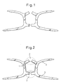
- FIG.1 shows four members (which form the closed curved belt portion) before the stitching to manufacture one example of the headgear of the present invention.
- the "closed curved belt" portion as indicated by the dashed line (1) in FIG. 2 , can be conceived.
- the stitched portions (2) providing the nonplanar structure to the closed curved belt in FIG. 2 are arranged on a plane, the gap between the opposed ends is larger on the peripheral side of the closed curved belt than on the inner peripheral side.
- FIG. 3 the angles of the stitched portions are illustrated.
- FIG. 4 shows a user wearing the headgear of the present invention.
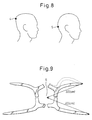
- FIG. 8 generally, the head shapes of Western and Japanese people are different.
- FIG. 9 one example of the headgear of the present invention having four straps suitable for the head shape of a Japanese person is shown.
- the center (6) of the closed curved belt is identical to the opistocranion of the head of a user.
- the distance from the center (6) of the closed curved belt to the ends of the straps is defined but the length of the strap itself does not matter.
- the shape of the strap as long as it is practicable.
- the shape as indicated in FIG. 9 by the dashed line can be used.
- FIGS. 10 to 15 Another example of the headgear according to the present invention is shown in FIGS. 10 to 15 , in which the headgear (wearing belt for respiratory mask) is provided with four holes (7) in the closed curved belt portion (1) for the purpose of the adjustment of the tension of each portion and the release of the humidity.
- the shape of the closed curved belt portion (1) is generally equilateral pentagonal and four straps (3) are provided.
- a Hook-and-Loop fastener portion (8) is provided at the tip of each strap (3). Consequently, for example, as shown in FIG.
- each strap (3) extends through the strap mounting hole of the nasal mask frame, and the intermediate portion of each strap (3) is folded back to attach the Hook-and-Loop fastener portion (8) to the surface of each strap (3), so that the nasal mask can be secured to the head of a user.
- the junctions of the closed curved belt portion (1) are not shown, but naturally, this headgear possesses the junctions in the necessary places.
- FIG. 13 only the right side view is shown, and the left side view is not shown because the right side view and left side view are symmetrical.
- a headgear which is used to secure a respiratory mask used in CPAP therapy or NIPPV therapy, etc., to the head of a user is provided.
Landscapes
- Health & Medical Sciences (AREA)
- General Health & Medical Sciences (AREA)
- Pulmonology (AREA)
- Life Sciences & Earth Sciences (AREA)
- Anesthesiology (AREA)
- Biomedical Technology (AREA)
- Heart & Thoracic Surgery (AREA)
- Hematology (AREA)
- Engineering & Computer Science (AREA)
- Animal Behavior & Ethology (AREA)
- Emergency Medicine (AREA)
- Public Health (AREA)
- Veterinary Medicine (AREA)
- Business, Economics & Management (AREA)
- Emergency Management (AREA)
- Respiratory Apparatuses And Protective Means (AREA)
Abstract
Description
- The present invention relates to a headgear which is used for securing a respiratory mask, to the head of a user, which is used in a CPAP (Continuous Positive Airway Pressure) therapy suitable for the treatment of sleep apnea syndrome, or an NIPPV (Nasal Intermittent Positive Pressure Ventilation) therapy suitable for treatment of ventilatory insufficiency and the like and a manufacturing method for the headgear.
- Continuous Positive Airway Pressure (CPAP) is one of the most effective treatments for sleep apnea syndrome. This treatment utilizes respiratory equipment providing a positive pressure gas in the range of 400 to 2000 Pa in the nostrils, or the nostrils and the mouth, or the face of a user during sleep. Further, Nasal Intermittent Positive Pressure Ventilation (NIPPV) is one of the most effective treatments for ventilatory insufficiency, utilizing respiratory equipment providing an intermittent positive pressure gas in the range of 400 to 2400 Pa in the nostrils of a user.
- As respiratory used in these therapies, there are nasal masks providing a positive pressure gas in the nostrils under pressure, full-face masks providing the positive pressure gas holding the nostrils and the mouth, and total face masks providing the positive pressure gas over the entire face.
- These respiratory masks are secure to the head of a user by a strap portion connected to a head mount of a headgear worn in the proximity of the opistocranion of the head of the user (JIS Z8500, ISO 7250).
- When performing treatment using the above stated equipment, in order to provide a continuous positive pressure gas to the nostrils and the like of a user generally, the respiratory mask is comprised of an elbow connecting a hose guiding the positive pressure gas for respiration, a frame connecting with the elbow to hold a mask cushion in a specified position, and a hollow mask cushion which is closely attached to the face of a user. Such a respiratory mask is closely attached to the face of a user by the tension of the stretchable strap portion of the headgear (for example, see
Patent Document 1,Patent Document 2, and Patent Document 3). - However, once, the respiratory mask is normally installed, it is known that displacement of the mask cushion occurs due to various causes while wearing. Because of that, measures have been taken which prevent or reduce the displacement corresponding to the respective causes. For example, to this end, a bellows is provided between the frame portion and the face contact portion of the mask cushion, in the nasal respiratory masks described in
Patent Document 1 andPatent Document 2 to prevent an influence on the mask cushion from the displacement of the frame portion which occurs by contact with bed clothing. Further, in a respiratory mask described inPatent Document 4, a flexible material is used for the wall around the connection portion of the positive pressure gas supply hose in order to reduce the displacement of the frame portion caused when it is pulled by the positive pressure gas supply hose connected to the frame. - Such a displacement causes the supplied positive pressure gas to leak, from the boundary between the mask cushion and the face, giving discomfort, irritation to the ocular region, and chills and the like to the user due to gas leaks, and depending on the case treatment is obliged to be discontinued. The gas leakage from the mask cushion in such conventional technology remarkably takes place in the root of nose region, nasal alae region and the like. For preventing such gas leaks, there is but one method which further strongly tightens the belt for securing a respiratory mask regardless of the location of the leak, but it is indicated that when wearing all night long for a long period of time during sleep and the like, it is possible that a respiratory mask can harm the face of a user.
[Patent Document 1] Japanese Patent Kokai No.11-000397
[Patent Document 2] Pamphlet of International Publication No.WO 01/097893
[Patent Document 3] Pamphlet of International Publication No.WO 98/04310
[Patent Document 4] Pamphlet of International Publication No.WO 96/17643 - However, in any one of the aforementioned technologies, the wearing of the headgear is necessary to secure the respiratory mask. Here, in order to adapt the headgear to the head of a user, if the material used in the headgear stretches easily, when it is pressurized, the headgear stretches too much, the respiratory mask rises up, and creates leakage of the positive pressure gas. Further, if a user lying down turns his or her body, the members forming the headgear are stretched by the weight of the respiratory mask, and hence, the respiratory mask is displaced, thus creating the leakage of the positive pressure gas.
- However, if using a material which is difficult to stretch for the headgear, adjustability to the shape of the head of a user becomes poor, and it contacts with the head only in the peripheral edges of each surface of the headgear. Therefore, there are the problems where the head becomes locally compressed, and when a respiratory mask is worn for a long period of time, pain occurs.
- Further, if the surface of a portion of the headgear rises up, catching on the pillow and other bed clothing, the displacement of headgear and accordingly the respiratory mask may occur.
- Namely, the problems remaining unresolved before the filing of the present application and to be resolved by the present invention are to satisfy both the requirements of the prevention of leakage of the positive pressure gas arising in the headgear and alleviation of the compression sensation by the headgear.
- According to the present invention, there is provided a headgear for securing a respiratory mask to a head of a user, wherein the respiratory mask contacts a face of the user to supply a positive pressure gas for respiration to the user, the headgear comprising: a head mounted portion which is mounted on the occipital of the user, and a strap connecting to the head mounted portion, said head mounted portion having at least one closed curved belt, said closed curved belt having thereon at least one junction, at least one of the junctions provides the closed curved belt with a nonplanar structure adaptable to a shape of the head of the user.
- According to another aspect of the present invention, there is provided a method of manufacturing a headgear mentioned above comprising: cutting off step to cut off a member forming a closed curved belt portion from a planar material, and connecting step to connect at least one pair of a first cut end and a second cut end in the cut out member to form at least one junction, wherein, in said cutting off step, a series of members forming the closed curved belt portion are cut off from the planar material; at least one place of the portion of the series of members corresponding to the closed curved belt portion is cut off along a first cutting line, and is further cut off along a second cutting line which is in the proximity of the first cutting line and is not parallel with and does not intersect the first cutting line, to form said at least one pair of first cut end and second cut end, or, each of the members forming said closed curved belt portions having said at least one pair of first cut end and second cut end is individually cut off from one or more planar materials.
- Here, the "head mounted portion" is the portion of the headgear that is secured to the periphery of the opistocranion of the head of a user by the tension of the strap. Namely, the head of the user is placed between the head mounted portion and the respiratory mask, and when both the head mounted portion and the mask are pressed against the head of the user by the tension of the strap, they are secured to the head of the user.
- Consequently, the strap of the headgear of the present invention is secured at its one end to the head mounted portion, and can be secured at the other end to the respiratory mask.
- The headgear of the present invention for securing a respiratory mask has advantages, that even the headgear using a clothing fabric which is difficult to stretch can prevent the leakage of the positive pressure gas because it possesses a stereoscopic structure which adapts to the shape of the head of a user, and that a good wearing feel can be maintained.
- Further, because the headgear of the present invention for securing a respiratory mask possesses a stereoscopic structure which adapts to the shape of the head of a user, even when the headgear touches pillows or other bed clothing, the headgear is hardly caught thereby, and as a result, it is possible to prevent the respiratory mask from moving.
- According to the present invention, there is also the advantage of obtaining these effects at a low cost.
-
-
FIG. 1 shows one example of the headgear of the present invention before stitching. -
FIG. 2 shows one example of the headgear of the present invention before stitching. -
FIG. 3 shows one example of the headgear of the present invention before stitching. -
FIG. 4 shows the headgear of the present invention, worn by a user. -
FIG. 5 schematically shows examples of the head mounted portion and strap in the headgear of the present invention. -
FIG. 6 schematically illustrates the number of straps and the attachment positions in the headgear of the present invention. -
FIG. 7 schematically illustrates the headgear of the present invention in which another annular structure is added to the head mounted portion. -
FIG. 8 compares the characteristics of head shapes of Western and Japanese persons. -
FIG. 9 shows an example of the headgear of the present invention suited for the head shape of a Japanese person. -
FIG. 10 is a perspective view of an example of the headgear of the present invention. -
FIG. 11 is a front view of one example of the headgear of the present invention. -
FIG. 12 is a back view of an example of the headgear of the present invention. -
FIG. 13 is a right side view of an example of the headgear of the present invention. -
FIG. 14 is a plan view of an example of the headgear of the present invention. -
FIG. 15 is a bottom view of an example of the headgear of the present invention. -
FIG. 16 is an explanatory view showing an example of the headgear of the present invention in use. - The headgear of the present invention has a head mounted portion which is worn on the occipital of a user and a strap connected thereto.
- As the material for the headgear of the present invention, for example, synthetic resin, fabric and the like can be used, but the effect of the present invention is difficult to obtain in an excessively stretchable material. For example, it is necessary to appropriately adjust the thickness and width, etc., of stretchable materials such as polyurethane foam, neoprene rubber, jerseys and make it difficult to stretch to some extent. Specifically, among the head mounted portion and the strap portion, it is desirable to produce at least the strap portion by the material where the stretch when pulled at 1.96 N is 0.05% to 20%, preferably 1% to 10%. If using this kind of material, the leakage of the positive pressure gas can be reduced, and, the wearability of the mask improves. If a material whose stretch when pulled at 1.96 N is larger than 20%, is used, leakage of the positive pressure gas may occur, and if a material whose stretch when pulled at 1.96 N is smaller than 0.05% is used, the adjustability to the shape of the head of a user is poor, and, when the respiratory mask is worn over a long period of time, there is the possibility of causing pain.
- Such a head mounted portion possesses at least one belt defined by a closed curve. If only to achieve the function of the headgear to secure a respiratory mask to the head of a user via the strap portion, the head mounted portion may be planar, but in fact, for the sake of providing air permeability to prevent sweating and weight savings and the like, it can use a closed curved belt shape in which the center portion is hollow. If one is skilled in the art, it is possible to decide the width of such a belt-like portion as needed, considering the stretchability, thickness, wearing feel, weight, cost and the like of the belt-like portion. If the width is too wide, generally, the weight and cost increase, and stretchability decreases. If the width is too narrow, the pressure to the head is concentrated in a narrow region and wearing feel deteriorates. If it is necessary, performing optimization experimentation can determine a specific numerical value. Additionally, it is not necessary for the width of the belt-like portion to be the same over the entire circumference of the closed curve.
- Provided that the function of the present invention is achieved, the shape of such a closed curved belt has no specific limitations, but for example, it is possible to make the shapes circular, elliptical or polygonal such as isosceles triangular and rectangular such as regular polygonal, equilateral triangular or squares or analogous shapes. Specifically, it is preferable that the shape of the closed curved belt is generally circular, elliptical, or regular polygonal, because the shape balance is good and it is easy to adjust the center of the closed curved belt to the opistocranion of the head of a user. Examples of the head mounted portion and the strap are typically shown in
FIG. 5 . InFIG. 5 , (A) shows the shape of the closed curved belt being generally elliptical, (B) shows the shape of the closed curved belt being generally rectangular, (C) shows the shape of the closed curved belt being generally regular pentagonal, and (D) shows the shape of the closed curved belt being generally regular triangular. - Such a closed curved belt possesses at least one junction which provides a nonplanar structure to the closed curved belt corresponding to the shape of the head of a user. When such a junction is provided, the end parts of the member forming the closed curved belt preferably do not overlap. This is because a step which causes catching on pillows and other bed clothing is not created.
- This kind of junction can be produced by various connection methods such as stitching, thermal adhering, the use of adhesive agents, or the use of hook-loop material (known as Velcro™), but among them, producing by stitching is preferable from the viewpoint of manufacturability, wearability and durability. Consequently, the junction produced by stitching is explained below, but the present invention is not limited to this.
- The cut portion (including the first cut end and the second cut end in the present invention) of such a closed curved belt, generally, is linear, but if the stitching does not cause displacement, and as far as a clearance gap is not created when the cut portions are stitched and the object of the present invention can be attained, other curved lines are also possible.
- The number of the stitched portions contributing to making such a nonplanar structure, can be either one or plural. The greater the number of the stitched portions, the more likely it is able to be adjusted to the shape of the head of a user, on the other hand, the labor in the manufacturing process increases. Consequently, two stitched portions contributing to making a nonplanar structure are typically provided. Further, if significance is placed on manufacturability, it is preferable that one stitched portion contributing to making a nonplanar structure is provided.
- Though, it is possible that the headgear of the present invention, other than the stitched portion which provides the closed curved belt with a nonplanar structure, for example, for the convenience of the manufacturing process, further possesses a stitched portion which does not contribute to making the nonplanar structure. For example, four stitched portions are provided wherein, every other two portions are used to make the nonplanar structure, and the other two portions do not contribute to making the nonplanar structure. The presence of four stitched portions is suitable for manufacturing the headgear of a four strap structure which when worn has an especially superior balance.
- When the stitched portion providing the nonplanar structure in the present invention is linear, it is possible to design the open angle to adapt to the shape of the head of a user, but when a user has the shape of a Japanese person's head, it is preferable that the sum of such open angles is 15 degrees or more. Here, the "open angle" is the angle defined by "the first cut line"(for example, the dashed lines P and S in
FIG. 3 ) and "the second cut line" (for example, the dashed lines Q and R inFIG. 3 ), or is the angle defined by "the first cut end" (for example, the end of the belt along the dashed lines P and S inFIG. 3 ) and "the second cut end" (for example, the end of the belt along the dashed lines Q and R inFIG. 3 ), which will be explained hereinafter in connection with the manufacturing method of the headgear of the present invention. - Provided that the strap portions in the headgear of the present invention bring about the effect of the present invention there are no restrictions in the number thereof, but there are generally 1 to 5 straps. Here, in order to explain examples of the attachment positions of the strap portions to the head mounted portion and the number thereof, examples of the structure of the head mounted portion and the strap portion are typically shown in
FIG. 6 . InFIG. 6 , (A) shows one strap provided, (B) shows two straps provided, (C) shows three straps provided, (D) shows four straps provided, and (E) shows five straps provided. Among these, it is preferable that four straps are provided as is specifically shown inFIG. 6 (D) , because when the headgear is worn on the head of a user, a superior balance can be obtained, and manufacturing is also easy. Additionally, if there is one strap as shown inFIG. 6 (A) , the one end is secured to the head mounted portion and, the other end extends through a respiratory mask, and is connected to a portion of the headgear via a connector and the like. - It is possible to manufacture the strap portion in the headgear of the present invention integrally with the aforementioned closed curved belt or it is possible to secure the strap portion produced separately from the closed curved belt to the closed curved belt. The tip of the strap portion is usually processed so that it can be suitably secured to the frame portion and the like of the respiratory mask. For example, it is connected to one of the connectors.
- The headgear of the present invention may have a structure other than the closed curved belt and the straps. For example, as shown in
FIG. 7 , another annular structure maybe provided in contact with the closed curved belt. Further, for the purpose of the adjustment of the tension of each portion and the release of humidity, it is possible to provide holes (for example, seereference numeral 7 inFIG. 10 ) in the closed curved belt and/or the strap in accordance with need. - One preferred embodiment of the headgear of the present invention provides the headgear which possesses a structure suitable for the shape of the head of a Japanese person. For example, as shown in
FIG. 8 , generally, the head of a Western person is such that the opistocranion (4) lies in a high position and the peripheral slope is steep, and the head of a Japanese person is such that the opistocranion (5) is low and the peripheral slope is gradual. Consequently, if a Japanese person uses a headgear suitable for the shape of the head of a Western person, namely, a headgear in which the area of the closed curved belt is small or the position of the closed curved belt lies in a relatively high position, because the closed curved belt tends not to engage with the opistocranion of the head of a Japanese person, this results in the occurrence of positional deviation. Note that, the user is referred to simply as Japanese person for the clarity of the explanation in the specification, but it goes without saying that the user is not limited to Japanese people and the headgear of the present invention can be appropriately used with any person, possessing a head structure close to the head structure of a Japanese person. - The headgear of the present invention suited for the head structure of such a Japanese person is, specifically, the headgear possessing four straps of which, two straps have a linear distance from the center of the closed curved belt to the ends of the straps of 35 cm to 45 cm (for example, 40 cm), and the remaining two straps have a linear distance from the center of the closed curved belt to the ends of the straps of 28 cm to 38 cm (for example, 33 cm).
- Here, "the center of the closed curved belt" is, for example, as shown in
FIG. 9 , when it is assumed that the opening defined and surrounded by the closed curved belt is a flat plate, the point (6) corresponding to the center of the flat plate. - Further, in another preferred embodiment of the headgear of the present invention, suitable for the head structure of a Japanese person, the center of the closed curved belt is positioned on the opistocranion of the head of a Japanese person when the headgear is worn, and the area defined and surrounded by the closed curved belt is 50 cm2 to 120 cm2.
- It is possible to refer to the standard human head model of Japanese persons, or to the statistic (AIST) data which are the of the head sizes of Japanese persons to determine the opistocranion of the head of a Japanese person. Note that, during the actual wearing, it is acceptable for the position of the opistocranion and the center of the closed curved belt to have some minor deviations because there is practically no great influence on the effect of the headgear of the present invention.
- Here, the area defined by the surrounding closed curved belt is determined to be 50 cm2 to 120 cm2, in order to wrap the slope near the opistocranion which is more gradual than Western persons.
- Furthermore, the present invention is directed to a manufacturing method of a headgear. Namely, the manufacturing method of the headgear of the present invention includes, a cutting off step to cut off the member forming the closed curved belt portion (for example, see
reference numeral 1 inFIG. 2 ) from a planar material, and a connecting step to connect at least one pair of first cut end and second cut end of the cut off member, to thereby form at least one junction. - Here, "member forming the closed curved belt portion" when the aforementioned closed curved belt portion and the strap portion are integrally manufactured, means the member (for example, the four blanks of an approximately Y-shape in
FIG. 1 ) having the closed curved belt portion and the strap portion, and when possessing the structures other than the closed curved belt and the strap, it means the member containing the structures, and when the closed curved belt portion and the strap portion are separately manufactured, it means the member containing only the closed curved belt portion. Further, "one pair of first cut end and second cut end", means a pair of ends of the member forming the closed curved belt portion to produce, for example, the junctions as indicated at 2 inFIG. 2 . Connecting the pair of cut ends produces the closed curved belt of the nonplanar structure adapted to the shape of the head of a user. - The cutting off step is specifically explained below. In the first method, a series of members forming the closed curved belt portion are cut off from a planar material; and at least one place of the portions of this series of material corresponding to the closed curved belt portions is cut off (the first cutting) along the first cutting line, and furthermore, is cut off (the second cutting) along the second cutting line which is in the proximity of the first cutting line and is not parallel with and does not intersect the first cutting line, to form at least one pair of a first cut end and a second cut end. Though, the first cutting and the second cutting are expressed mainly for convenience sake, in fact, it is preferable to perform the two cuttings simultaneously.
- Here, "a series of members forming the closed curved belt portions" refers to a series of members possessing the closed curved belts of a planar structure, and when the closed curved belt portion and the strap portion are integrally manufactured as mentioned above, it means a series of members including the closed curved belt portions and the strap portions, and when a structure other than the closed curved belt and the strap is provided, it means a series of members including this structure, and when the closed curved belt portions and the strap portion are separately manufactured, it means a series of members including only the closed curved belt portions.
- The first cutting line usually is a straight line.
- On the other hand, the second cutting line must
- a) be in proximity to the first cutting line,
- b) not be parallel with the first cutting line,
- c) not intersect with the first cutting line, and
- d) be obtained by sewing the corresponding cut ends together without overlapping to form the closed curved belt adapted to the shape of the head of a user.
- The meaning of "in proximity" refers to the range which does not generate the waste of material by excessive chipping, but the range is not significant as long as the headgear of the present invention can be obtained. Generally, the second cutting line begins from one end of the first cutting line. If the second cutting line is parallel with the first cutting line, stitching of the cut ends does not provide the closed curved belt with the nonplanar structure. If the second cutting line intersects the first cutting line, it is not possible to sew together the corresponding cut ends over the entire length.
- In a second method of the cutting off step, each of the members forming the closed curved belt portion having at least one pair of a first cut end and a second cut end is individually cut off from one or more planar materials. In this second method, the members can advantageously be cut off from small planar materials, and, a cost decrease can be expected by the application of the materials which are left over. Furthermore, compared to the aforementioned first method in which the member forming the closed curved belt portion is cut off from a large planar material, the amount of waste of the cut material can be reduced, and the manufacture equipment can be of a small size, yielding various merits in regards to manufacturing.
- In the cutting off step, it is preferable to produce at least one pair of a first cut end and a second cut end with the sum of the open angles of the first cut end and the second cut end being 15 degrees or more when the member forming the closed curved belt portion lies in plane. Thus, it is possible to make the three dimensional shape of the closed curved belt adaptable to the shape of the head of a Japanese person. For example, as shown in
FIG. 3 , when the angles of the first cut end and the second cut end from the tangential direction to the closed curve are respectively 60 degrees and 120 degrees, 50 degrees and 130 degrees, the cut ends respectively form the open angles of 60 degrees and 80 degrees (total 140 degrees) on a plane. The above-mentioned open angles make the headgear adaptable to the shape of the head of a Japanese person satisfactorily. - Below, specific examples of the present invention are further explained in detail with reference to the drawings.
-
FIG.1 shows four members (which form the closed curved belt portion) before the stitching to manufacture one example of the headgear of the present invention. If arranged as shown inFIG. 1 , the "closed curved belt" portion as indicated by the dashed line (1) inFIG. 2 , can be conceived. When the stitched portions (2) providing the nonplanar structure to the closed curved belt inFIG. 2 are arranged on a plane, the gap between the opposed ends is larger on the peripheral side of the closed curved belt than on the inner peripheral side. When all of the four stitched portions are stitched, the closed curved belt of the nonplanar structure is obtained. InFIG. 3 , the angles of the stitched portions are illustrated.FIG. 4 shows a user wearing the headgear of the present invention. - As shown in
FIG. 8 , generally, the head shapes of Western and Japanese people are different. InFIG. 9 , one example of the headgear of the present invention having four straps suitable for the head shape of a Japanese person is shown. Here, it is assumed that the center (6) of the closed curved belt is identical to the opistocranion of the head of a user. Here, the distance from the center (6) of the closed curved belt to the ends of the straps is defined but the length of the strap itself does not matter. Further, there are no restrictions regarding the shape of the strap as long as it is practicable. For example, the shape as indicated inFIG. 9 by the dashed line can be used. - Another example of the headgear according to the present invention is shown in
FIGS. 10 to 15 , in which the headgear (wearing belt for respiratory mask) is provided with four holes (7) in the closed curved belt portion (1) for the purpose of the adjustment of the tension of each portion and the release of the humidity. In this headgear, the shape of the closed curved belt portion (1) is generally equilateral pentagonal and four straps (3) are provided. A Hook-and-Loop fastener portion (8) is provided at the tip of each strap (3). Consequently, for example, as shown inFIG. 16 , the tip of each strap (3) extends through the strap mounting hole of the nasal mask frame, and the intermediate portion of each strap (3) is folded back to attach the Hook-and-Loop fastener portion (8) to the surface of each strap (3), so that the nasal mask can be secured to the head of a user. Note that, inFIGS. 10 to 15 , the junctions of the closed curved belt portion (1) are not shown, but naturally, this headgear possesses the junctions in the necessary places. Further, inFIG. 13 , only the right side view is shown, and the left side view is not shown because the right side view and left side view are symmetrical. - According to the present invention, a headgear which is used to secure a respiratory mask used in CPAP therapy or NIPPV therapy, etc., to the head of a user is provided.
Claims (14)
- A headgear for securing a respiratory mask to a head of a user, wherein the respiratory mask contacts a face of the user to supply a positive pressure gas for respiration to the user, the headgear comprising:a head mounted portion which is mounted on the occipital of the user, anda strap connecting to the head mounted portion,said head mounted portion having at least one closed curved belt,said closed curved belt having thereon at least one junction, at least one of the junctions provides the closed curved belt with a nonplanar structure adaptable to a shape of the head of the user.
- A headgear according to claim 1 wherein said junction is formed by stitching.
- A headgear according to claim 1 or 2 wherein it comprises at least two junctions that provide the nonplanar structure.
- A headgear according to claim 3 wherein the number of said junctions in total is four.
- A headgear according to claim 1 or 2 wherein it comprises one junction which provides the nonplanar structure.
- A headgear according to any one of claims 1 to 5 wherein a sum of open angles of the junctions which provide the nonplanar structure is not less than 15 degrees.
- A headgear according to any one of claims 1 to 6 wherein said closed curve is generally circular, elliptical, or regular polygonal.
- A headgear according to any one of claims 1 to 7 wherein the number of said straps connected to said head mounted portion is one to five.
- A headgear according to any one of claims 1 to 7 wherein the number of said straps connected to said head mounted portion is four.
- A headgear according to claim 9 wherein said straps include two straps of which a linear distance from a center of the closed curved belt to ends of the straps is 35 cm to 45 cm, and, two straps of which a linear distance from the center of the closed curved belt to ends of the straps is 28 cm to 38 cm.
- A headgear according to any one of claims 1 to 10 wherein when it is worn on the user, the center of the closed curved belt lies in the vicinity of the opistocranion of the head of the user,
and the area defined and surrounded by the closed curved belt is 50 cm2 to 120 cm2. - A headgear according to any one of claims 1 to 11 wherein among the head mounted portion and the strap, at least the strap is made of a material that has a stretch of 0.05% to 20% when pulled at 1.96 N.
- A method of manufacturing a headgear according to any one of claims 1 to 12, the method comprising:cutting off step to cut off a member forming a closed curved belt portion from a planar material, andconnecting step to connect at least one pair of a first cut end and a second cut end in the cut off member to form at least one junction, wherein, in said cutting off step,a series of members forming the closed curved belt portion are cut off from the planar material; at least one place of the portion of the series of members corresponding to the closed curved belt portion is cut off along a first cutting line, and is further cut off along a second cutting line which is in the proximity of the first cutting line and is not parallel with and does not intersect the first cutting line, to form said at least one pair of first cut end and second cut end,or, each of the members forming said closed curved belt portions having said at least one pair of first cut end and second cut end is individually cut off from one or more planar materials.
- A manufacturing method of a headgear according to claim 13 wherein in said cutting off step, said at least one pair of a first cut end and a second cut end are formed so that the sum of open angles of the first cut end and the second cut end is no less than 15 degrees when said member forming the closed curved belt portion lies in a plane.
Applications Claiming Priority (2)
| Application Number | Priority Date | Filing Date | Title |
|---|---|---|---|
| JP2006331958 | 2006-12-08 | ||
| PCT/JP2007/070504 WO2008068966A1 (en) | 2006-12-08 | 2007-10-16 | Headgear and process for producing the same |
Publications (3)
| Publication Number | Publication Date |
|---|---|
| EP2090327A1 true EP2090327A1 (en) | 2009-08-19 |
| EP2090327A4 EP2090327A4 (en) | 2012-08-22 |
| EP2090327B1 EP2090327B1 (en) | 2018-12-05 |
Family
ID=39491876
Family Applications (1)
| Application Number | Title | Priority Date | Filing Date |
|---|---|---|---|
| EP07830238.7A Active EP2090327B1 (en) | 2006-12-08 | 2007-10-16 | Headgear and process for producing the same |
Country Status (11)
| Country | Link |
|---|---|
| US (1) | US8393327B2 (en) |
| EP (1) | EP2090327B1 (en) |
| JP (1) | JP5164854B2 (en) |
| KR (1) | KR20090086578A (en) |
| CN (1) | CN101553270B (en) |
| AU (1) | AU2007330182B2 (en) |
| CA (1) | CA2671591A1 (en) |
| ES (1) | ES2710914T3 (en) |
| MY (1) | MY149663A (en) |
| TW (1) | TWI471148B (en) |
| WO (1) | WO2008068966A1 (en) |
Families Citing this family (53)
| Publication number | Priority date | Publication date | Assignee | Title |
|---|---|---|---|---|
| AU2004212633B2 (en) | 2003-02-21 | 2010-12-09 | ResMed Pty Ltd | Nasal assembly |
| CN101214402B (en) | 2003-12-31 | 2013-08-21 | 雷斯梅德有限公司 | Respiration device |
| WO2005079726A1 (en) | 2004-02-23 | 2005-09-01 | Fisher & Paykel Healthcare Limited | Breathing assistance apparatus |
| WO2005094928A1 (en) | 2004-04-02 | 2005-10-13 | Fisher & Paykel Healthcare Limited | Breathing assistance apparatus |
| EP1740247B1 (en) | 2004-04-15 | 2012-09-26 | ResMed Limited | Positive-air-pressure machine conduit |
| NZ563608A (en) | 2005-06-06 | 2011-03-31 | Resmed Ltd | A mask with upper and lower stabilization parts contoured to the shape of a human face as part of the straps |
| ES2954589T3 (en) | 2006-07-14 | 2023-11-23 | Fisher & Paykel Healthcare Ltd | Respiratory assistance device |
| WO2008011683A1 (en) | 2006-07-28 | 2008-01-31 | Resmed Ltd | Delivery of respiratory therapy |
| ES2592677T3 (en) | 2006-07-28 | 2016-12-01 | Resmed Limited | Administration of respiratory therapy |
| WO2008070929A1 (en) | 2006-12-15 | 2008-06-19 | Resmed Ltd | Delivery of respiratory therapy |
| US10792451B2 (en) | 2008-05-12 | 2020-10-06 | Fisher & Paykel Healthcare Limited | Patient interface and aspects thereof |
| US10258757B2 (en) | 2008-05-12 | 2019-04-16 | Fisher & Paykel Healthcare Limited | Patient interface and aspects thereof |
| NZ577415A (en) | 2008-06-04 | 2011-01-28 | Resmed Ltd | Breathing apparatus attached to the face using a hook and loop fastener having one side adhered to the skin |
| WO2009146484A1 (en) | 2008-06-05 | 2009-12-10 | Resmed Ltd | Treatment of respiratory conditions |
| US11660413B2 (en) | 2008-07-18 | 2023-05-30 | Fisher & Paykel Healthcare Limited | Breathing assistance apparatus |
| ES2652561T3 (en) | 2008-10-10 | 2018-02-05 | Fisher & Paykel Healthcare Limited | Nasal pads for a patient interface |
| AU2016201534B2 (en) * | 2008-12-10 | 2017-12-07 | ResMed Pty Ltd | Headgear for Masks |
| DE202009018927U1 (en) | 2008-12-10 | 2014-07-17 | Resmed Limited | Head masks for masks |
| NZ740593A (en) | 2009-06-02 | 2019-10-25 | ResMed Pty Ltd | Unobtrusive nasal mask |
| EP3741418B1 (en) | 2009-11-18 | 2024-05-08 | Fisher & Paykel Healthcare Limited | Nasal interface |
| US8839785B2 (en) * | 2010-03-10 | 2014-09-23 | 3M Innovative Properties Company | Respirator harness having collapsible head cradle |
| USD695887S1 (en) | 2010-09-10 | 2013-12-17 | Resmed Limited | Respiratory mask |
| EP3231470B1 (en) | 2010-09-30 | 2023-01-11 | ResMed Pty Ltd | Mask system |
| EP3669920B1 (en) | 2010-09-30 | 2024-10-30 | ResMed Pty Ltd | Patient interface systems |
| EP4640259A3 (en) | 2010-10-08 | 2025-11-12 | Fisher & Paykel Healthcare Limited | Mask seal assembly |
| US10603456B2 (en) | 2011-04-15 | 2020-03-31 | Fisher & Paykel Healthcare Limited | Interface comprising a nasal sealing portion |
| DK3117861T3 (en) | 2011-04-15 | 2021-06-21 | Fisher & Paykel Healthcare Ltd | INTERFACE INCLUDING A ROLLING NOSE |
| CN103957975A (en) * | 2011-10-06 | 2014-07-30 | 皇家飞利浦有限公司 | Ergonomically formed headgear strap |
| JP6165753B2 (en) * | 2011-11-03 | 2017-07-19 | コーニンクレッカ フィリップス エヌ ヴェKoninklijke Philips N.V. | Multi-material single face headgear |
| US9764106B2 (en) | 2012-02-28 | 2017-09-19 | Koninklijke Philips N.V. | Unidirectional flexion clip |
| WO2013172719A1 (en) | 2012-05-16 | 2013-11-21 | Fisher & Paykel Healthcare Limited | Headgear, interface and an assembly |
| US12390612B2 (en) | 2012-07-27 | 2025-08-19 | ResMed Pty Ltd | Patient interface with elastic headgear |
| BR112015001899A2 (en) | 2012-07-27 | 2017-07-04 | Resmed Ltd | patient interface and method to produce it. |
| US9974915B2 (en) | 2012-07-27 | 2018-05-22 | Resmed Limited | Elastic headgear |
| WO2014025267A1 (en) | 2012-08-08 | 2014-02-13 | Fisher & Paykel Healthcare Limited | Headgear for patient interface |
| WO2014038959A1 (en) | 2012-09-04 | 2014-03-13 | Fisher & Paykel Healthcare Limited | Valsalva mask |
| NZ744244A (en) | 2013-01-16 | 2020-01-31 | ResMed Pty Ltd | Patient interface and method for making same |
| CN110433373A (en) | 2013-10-18 | 2019-11-12 | 费雪派克医疗保健有限公司 | Wear tool |
| EP4378507A3 (en) | 2013-11-15 | 2024-09-18 | ResMed Pty Ltd | Patient interface and method for making same |
| EP3978056B1 (en) | 2013-11-27 | 2023-12-27 | Fisher & Paykel Healthcare Limited | Headgear assembly for breathing interface |
| USD770036S1 (en) | 2013-11-27 | 2016-10-25 | Fisher & Paykel Healthcare Limited | Breathing interface assembly |
| USD760379S1 (en) | 2014-01-31 | 2016-06-28 | Resmed Limited | Headgear connector for patient interface |
| GB2585605B (en) | 2014-08-25 | 2021-07-07 | Fisher & Paykel Healthcare Ltd | Respiratory mask and related portions, components or sub-assemblies |
| CN107206202A (en) * | 2014-10-16 | 2017-09-26 | Ikk株式会社 | Artificial respirator is installed with fixed tool |
| EP3988153B1 (en) | 2015-03-31 | 2024-04-24 | Fisher & Paykel Healthcare Limited | A user interface for supplying gases to an airway |
| WO2018002169A1 (en) * | 2016-06-29 | 2018-01-04 | Koninklijke Philips N.V. | Method of generating a configuration for a customized headgear |
| CN121668497A (en) | 2016-08-11 | 2026-03-17 | 费雪派克医疗保健有限公司 | Collapsible catheter, patient interface, and headgear connector |
| USD895105S1 (en) | 2016-10-24 | 2020-09-01 | ResMed Pty Ltd | Combined cushion and frame module for patient interface |
| USD823454S1 (en) | 2017-02-23 | 2018-07-17 | Fisher & Paykel Healthcare Limited | Cushion assembly for breathing mask assembly |
| USD824020S1 (en) | 2017-02-23 | 2018-07-24 | Fisher & Paykel Healthcare Limited | Cushion assembly for breathing mask assembly |
| USD823455S1 (en) | 2017-02-23 | 2018-07-17 | Fisher & Paykel Healthcare Limited | Cushion assembly for breathing mask assembly |
| WO2019104575A1 (en) * | 2017-11-30 | 2019-06-06 | 苏州欧博时装有限公司 | Knitted binding band for respirator mask body |
| CN117959549A (en) * | 2023-12-29 | 2024-05-03 | 北京怡和嘉业医疗科技股份有限公司 | A mask system, a ventilation device and a method for manufacturing a mask |
Family Cites Families (20)
| Publication number | Priority date | Publication date | Assignee | Title |
|---|---|---|---|---|
| JP3001864U (en) * | 1994-03-09 | 1994-09-06 | 美津濃株式会社 | Sport supporters |
| AUPM997394A0 (en) | 1994-12-09 | 1995-01-12 | University Of Sydney, The | Gas delivery mask |
| AUPO126596A0 (en) | 1996-07-26 | 1996-08-22 | Resmed Limited | A nasal mask and mask cushion therefor |
| JP4290773B2 (en) | 1997-06-11 | 2009-07-08 | 帝人株式会社 | Breathing nose mask |
| US6732733B1 (en) | 1997-10-03 | 2004-05-11 | 3M Innovative Properties Company | Half-mask respirator with head harness assembly |
| FR2778575B1 (en) * | 1998-05-12 | 2000-07-28 | Intertechnique Sa | RESPIRATORY PROTECTION EQUIPMENT WITH FAST SETUP |
| AUPP812199A0 (en) * | 1999-01-12 | 1999-02-04 | Resmed Limited | Headgear |
| US6986352B2 (en) | 2000-06-22 | 2006-01-17 | Resmed Limited | Mask with gusset |
| US6418929B1 (en) * | 2000-09-18 | 2002-07-16 | Suzanne H. Norfleet | Infant oxygen mask |
| JP3785431B2 (en) * | 2002-04-09 | 2006-06-14 | 興研株式会社 | Banded mask |
| US8997742B2 (en) * | 2002-04-23 | 2015-04-07 | Resmed Limited | Ergonomic and adjustable respiratory mask assembly with cushion |
| AUPS192602A0 (en) | 2002-04-23 | 2002-05-30 | Resmed Limited | Nasal mask |
| NZ747187A (en) * | 2002-11-08 | 2020-05-29 | ResMed Pty Ltd | Headgear assembly for a respiratory mask assembly |
| CA2451192A1 (en) * | 2002-12-23 | 2004-06-23 | Lisa Semeniuk | Method and apparatus for preventing ear abrasion |
| WO2005032634A1 (en) * | 2003-10-08 | 2005-04-14 | Fisher & Paykel Healthcare Limited | Breathing assistance apparatus |
| AU2005256167A1 (en) * | 2004-06-25 | 2006-01-05 | Resmed Limited | Forehead support for a patient interface |
| US9492627B2 (en) * | 2005-01-03 | 2016-11-15 | Resmed Limited | Headgear assembly for patient interface |
| NZ563608A (en) | 2005-06-06 | 2011-03-31 | Resmed Ltd | A mask with upper and lower stabilization parts contoured to the shape of a human face as part of the straps |
| US7600514B2 (en) * | 2005-06-17 | 2009-10-13 | Nellcor Puritan Bennett Llc | System and method for securing a gas delivery mask onto a subject's head |
| US8286635B2 (en) | 2005-07-08 | 2012-10-16 | Resmed Limited | Headgear for mask assembly |
-
2007
- 2007-10-16 JP JP2008548196A patent/JP5164854B2/en active Active
- 2007-10-16 AU AU2007330182A patent/AU2007330182B2/en not_active Ceased
- 2007-10-16 CA CA002671591A patent/CA2671591A1/en not_active Abandoned
- 2007-10-16 ES ES07830238T patent/ES2710914T3/en active Active
- 2007-10-16 CN CN2007800453315A patent/CN101553270B/en active Active
- 2007-10-16 US US12/517,751 patent/US8393327B2/en active Active
- 2007-10-16 KR KR1020097011543A patent/KR20090086578A/en not_active Abandoned
- 2007-10-16 EP EP07830238.7A patent/EP2090327B1/en active Active
- 2007-10-16 WO PCT/JP2007/070504 patent/WO2008068966A1/en not_active Ceased
- 2007-10-16 MY MYPI20092129A patent/MY149663A/en unknown
- 2007-10-18 TW TW96138994A patent/TWI471148B/en not_active IP Right Cessation
Also Published As
| Publication number | Publication date |
|---|---|
| ES2710914T3 (en) | 2019-04-29 |
| CA2671591A1 (en) | 2008-06-12 |
| JPWO2008068966A1 (en) | 2010-03-18 |
| CN101553270B (en) | 2013-03-13 |
| EP2090327A4 (en) | 2012-08-22 |
| TWI471148B (en) | 2015-02-01 |
| KR20090086578A (en) | 2009-08-13 |
| AU2007330182B2 (en) | 2012-11-08 |
| AU2007330182A1 (en) | 2008-06-12 |
| CN101553270A (en) | 2009-10-07 |
| US20090250065A1 (en) | 2009-10-08 |
| US8393327B2 (en) | 2013-03-12 |
| EP2090327B1 (en) | 2018-12-05 |
| HK1137156A1 (en) | 2010-07-23 |
| WO2008068966A1 (en) | 2008-06-12 |
| MY149663A (en) | 2013-09-30 |
| TW200826983A (en) | 2008-07-01 |
| JP5164854B2 (en) | 2013-03-21 |
Similar Documents
| Publication | Publication Date | Title |
|---|---|---|
| US8393327B2 (en) | Headgear and its manufacturing method | |
| US20210236761A1 (en) | Pad for a mask | |
| CN105992603B (en) | headgear | |
| EP2744548B1 (en) | Ergonomically formed headgear straps | |
| JP6868664B2 (en) | Patient interface with adaptive system, respiratory mask and pad for the adaptive system | |
| CN203989377U (en) | Patient interface, location and rock-steady structure, patient's connected system and buffer component | |
| EP2444113B1 (en) | Respiratory interface device with flexible cover | |
| JP2024174140A (en) | Headgear for masks | |
| CN108310578B (en) | Patient interface and method for manufacturing the same | |
| CN101837156B (en) | Headgear assembly for a respiratory mask assembly | |
| US6418928B1 (en) | Multi-seal respirator mask | |
| US7036508B2 (en) | Harness assembly for a nasal mask | |
| US20120204881A1 (en) | Pad for a mask | |
| EP2747822B1 (en) | Multiple-material, single-plane headgear | |
| US20140000615A1 (en) | System for reduction of air leaks with use of cpap masks | |
| EP4221796B1 (en) | Wrap-back headgear for patient interface | |
| HK1133215A (en) | Headgear and process for producing the same | |
| HK1137156B (en) | Headgear and process for producing the same |
Legal Events
| Date | Code | Title | Description |
|---|---|---|---|
| PUAI | Public reference made under article 153(3) epc to a published international application that has entered the european phase |
Free format text: ORIGINAL CODE: 0009012 |
|
| 17P | Request for examination filed |
Effective date: 20090527 |
|
| AK | Designated contracting states |
Kind code of ref document: A1 Designated state(s): AT BE BG CH CY CZ DE DK EE ES FI FR GB GR HU IE IS IT LI LT LU LV MC MT NL PL PT RO SE SI SK TR |
|
| DAX | Request for extension of the european patent (deleted) | ||
| REG | Reference to a national code |
Ref country code: HK Ref legal event code: DE Ref document number: 1133215 Country of ref document: HK |
|
| A4 | Supplementary search report drawn up and despatched |
Effective date: 20120723 |
|
| RIC1 | Information provided on ipc code assigned before grant |
Ipc: A62B 18/08 20060101ALI20120717BHEP Ipc: A61M 16/06 20060101AFI20120717BHEP |
|
| STAA | Information on the status of an ep patent application or granted ep patent |
Free format text: STATUS: EXAMINATION IS IN PROGRESS |
|
| 17Q | First examination report despatched |
Effective date: 20170201 |
|
| GRAP | Despatch of communication of intention to grant a patent |
Free format text: ORIGINAL CODE: EPIDOSNIGR1 |
|
| STAA | Information on the status of an ep patent application or granted ep patent |
Free format text: STATUS: GRANT OF PATENT IS INTENDED |
|
| INTG | Intention to grant announced |
Effective date: 20180516 |
|
| GRAS | Grant fee paid |
Free format text: ORIGINAL CODE: EPIDOSNIGR3 |
|
| GRAA | (expected) grant |
Free format text: ORIGINAL CODE: 0009210 |
|
| GRAA | (expected) grant |
Free format text: ORIGINAL CODE: 0009210 |
|
| STAA | Information on the status of an ep patent application or granted ep patent |
Free format text: STATUS: THE PATENT HAS BEEN GRANTED |
|
| AK | Designated contracting states |
Kind code of ref document: B1 Designated state(s): AT BE BG CH CY CZ DE DK EE ES FI FR GB GR HU IE IS IT LI LT LU LV MC MT NL PL PT RO SE SI SK TR |
|
| REG | Reference to a national code |
Ref country code: GB Ref legal event code: FG4D |
|
| REG | Reference to a national code |
Ref country code: CH Ref legal event code: EP |
|
| REG | Reference to a national code |
Ref country code: AT Ref legal event code: REF Ref document number: 1072290 Country of ref document: AT Kind code of ref document: T Effective date: 20181215 |
|
| REG | Reference to a national code |
Ref country code: IE Ref legal event code: FG4D |
|
| REG | Reference to a national code |
Ref country code: DE Ref legal event code: R096 Ref document number: 602007057063 Country of ref document: DE |
|
| REG | Reference to a national code |
Ref country code: NL Ref legal event code: MP Effective date: 20181205 |
|
| REG | Reference to a national code |
Ref country code: AT Ref legal event code: MK05 Ref document number: 1072290 Country of ref document: AT Kind code of ref document: T Effective date: 20181205 |
|
| REG | Reference to a national code |
Ref country code: LT Ref legal event code: MG4D |
|
| REG | Reference to a national code |
Ref country code: ES Ref legal event code: FG2A Ref document number: 2710914 Country of ref document: ES Kind code of ref document: T3 Effective date: 20190429 |
|
| PG25 | Lapsed in a contracting state [announced via postgrant information from national office to epo] |
Ref country code: AT Free format text: LAPSE BECAUSE OF FAILURE TO SUBMIT A TRANSLATION OF THE DESCRIPTION OR TO PAY THE FEE WITHIN THE PRESCRIBED TIME-LIMIT Effective date: 20181205 Ref country code: BG Free format text: LAPSE BECAUSE OF FAILURE TO SUBMIT A TRANSLATION OF THE DESCRIPTION OR TO PAY THE FEE WITHIN THE PRESCRIBED TIME-LIMIT Effective date: 20190305 Ref country code: FI Free format text: LAPSE BECAUSE OF FAILURE TO SUBMIT A TRANSLATION OF THE DESCRIPTION OR TO PAY THE FEE WITHIN THE PRESCRIBED TIME-LIMIT Effective date: 20181205 Ref country code: LT Free format text: LAPSE BECAUSE OF FAILURE TO SUBMIT A TRANSLATION OF THE DESCRIPTION OR TO PAY THE FEE WITHIN THE PRESCRIBED TIME-LIMIT Effective date: 20181205 Ref country code: LV Free format text: LAPSE BECAUSE OF FAILURE TO SUBMIT A TRANSLATION OF THE DESCRIPTION OR TO PAY THE FEE WITHIN THE PRESCRIBED TIME-LIMIT Effective date: 20181205 |
|
| PG25 | Lapsed in a contracting state [announced via postgrant information from national office to epo] |
Ref country code: SE Free format text: LAPSE BECAUSE OF FAILURE TO SUBMIT A TRANSLATION OF THE DESCRIPTION OR TO PAY THE FEE WITHIN THE PRESCRIBED TIME-LIMIT Effective date: 20181205 Ref country code: GR Free format text: LAPSE BECAUSE OF FAILURE TO SUBMIT A TRANSLATION OF THE DESCRIPTION OR TO PAY THE FEE WITHIN THE PRESCRIBED TIME-LIMIT Effective date: 20190306 |
|
| PG25 | Lapsed in a contracting state [announced via postgrant information from national office to epo] |
Ref country code: NL Free format text: LAPSE BECAUSE OF FAILURE TO SUBMIT A TRANSLATION OF THE DESCRIPTION OR TO PAY THE FEE WITHIN THE PRESCRIBED TIME-LIMIT Effective date: 20181205 |
|
| PG25 | Lapsed in a contracting state [announced via postgrant information from national office to epo] |
Ref country code: PT Free format text: LAPSE BECAUSE OF FAILURE TO SUBMIT A TRANSLATION OF THE DESCRIPTION OR TO PAY THE FEE WITHIN THE PRESCRIBED TIME-LIMIT Effective date: 20190405 Ref country code: PL Free format text: LAPSE BECAUSE OF FAILURE TO SUBMIT A TRANSLATION OF THE DESCRIPTION OR TO PAY THE FEE WITHIN THE PRESCRIBED TIME-LIMIT Effective date: 20181205 Ref country code: CZ Free format text: LAPSE BECAUSE OF FAILURE TO SUBMIT A TRANSLATION OF THE DESCRIPTION OR TO PAY THE FEE WITHIN THE PRESCRIBED TIME-LIMIT Effective date: 20181205 |
|
| PG25 | Lapsed in a contracting state [announced via postgrant information from national office to epo] |
Ref country code: IS Free format text: LAPSE BECAUSE OF FAILURE TO SUBMIT A TRANSLATION OF THE DESCRIPTION OR TO PAY THE FEE WITHIN THE PRESCRIBED TIME-LIMIT Effective date: 20190405 Ref country code: EE Free format text: LAPSE BECAUSE OF FAILURE TO SUBMIT A TRANSLATION OF THE DESCRIPTION OR TO PAY THE FEE WITHIN THE PRESCRIBED TIME-LIMIT Effective date: 20181205 Ref country code: RO Free format text: LAPSE BECAUSE OF FAILURE TO SUBMIT A TRANSLATION OF THE DESCRIPTION OR TO PAY THE FEE WITHIN THE PRESCRIBED TIME-LIMIT Effective date: 20181205 Ref country code: SK Free format text: LAPSE BECAUSE OF FAILURE TO SUBMIT A TRANSLATION OF THE DESCRIPTION OR TO PAY THE FEE WITHIN THE PRESCRIBED TIME-LIMIT Effective date: 20181205 |
|
| REG | Reference to a national code |
Ref country code: DE Ref legal event code: R097 Ref document number: 602007057063 Country of ref document: DE |
|
| PLBE | No opposition filed within time limit |
Free format text: ORIGINAL CODE: 0009261 |
|
| STAA | Information on the status of an ep patent application or granted ep patent |
Free format text: STATUS: NO OPPOSITION FILED WITHIN TIME LIMIT |
|
| PG25 | Lapsed in a contracting state [announced via postgrant information from national office to epo] |
Ref country code: DK Free format text: LAPSE BECAUSE OF FAILURE TO SUBMIT A TRANSLATION OF THE DESCRIPTION OR TO PAY THE FEE WITHIN THE PRESCRIBED TIME-LIMIT Effective date: 20181205 Ref country code: SI Free format text: LAPSE BECAUSE OF FAILURE TO SUBMIT A TRANSLATION OF THE DESCRIPTION OR TO PAY THE FEE WITHIN THE PRESCRIBED TIME-LIMIT Effective date: 20181205 |
|
| 26N | No opposition filed |
Effective date: 20190906 |
|
| PG25 | Lapsed in a contracting state [announced via postgrant information from national office to epo] |
Ref country code: TR Free format text: LAPSE BECAUSE OF FAILURE TO SUBMIT A TRANSLATION OF THE DESCRIPTION OR TO PAY THE FEE WITHIN THE PRESCRIBED TIME-LIMIT Effective date: 20181205 |
|
| PG25 | Lapsed in a contracting state [announced via postgrant information from national office to epo] |
Ref country code: MC Free format text: LAPSE BECAUSE OF FAILURE TO SUBMIT A TRANSLATION OF THE DESCRIPTION OR TO PAY THE FEE WITHIN THE PRESCRIBED TIME-LIMIT Effective date: 20181205 |
|
| REG | Reference to a national code |
Ref country code: HK Ref legal event code: WD Ref document number: 1133215 Country of ref document: HK Ref country code: CH Ref legal event code: PL |
|
| REG | Reference to a national code |
Ref country code: DE Ref legal event code: R082 Ref document number: 602007057063 Country of ref document: DE Representative=s name: HOFFMANN - EITLE PATENT- UND RECHTSANWAELTE PA, DE Ref country code: DE Ref legal event code: R081 Ref document number: 602007057063 Country of ref document: DE Owner name: TEIJIN LIMITED, OSAKA-SHI, JP Free format text: FORMER OWNER: TEIJIN PHARMA LIMITED, TOKYO, JP |
|
| PG25 | Lapsed in a contracting state [announced via postgrant information from national office to epo] |
Ref country code: CH Free format text: LAPSE BECAUSE OF NON-PAYMENT OF DUE FEES Effective date: 20191031 Ref country code: LI Free format text: LAPSE BECAUSE OF NON-PAYMENT OF DUE FEES Effective date: 20191031 Ref country code: LU Free format text: LAPSE BECAUSE OF NON-PAYMENT OF DUE FEES Effective date: 20191016 |
|
| REG | Reference to a national code |
Ref country code: BE Ref legal event code: MM Effective date: 20191031 |
|
| PG25 | Lapsed in a contracting state [announced via postgrant information from national office to epo] |
Ref country code: BE Free format text: LAPSE BECAUSE OF NON-PAYMENT OF DUE FEES Effective date: 20191031 |
|
| GBPC | Gb: european patent ceased through non-payment of renewal fee |
Effective date: 20191016 |
|
| PG25 | Lapsed in a contracting state [announced via postgrant information from national office to epo] |
Ref country code: FR Free format text: LAPSE BECAUSE OF NON-PAYMENT OF DUE FEES Effective date: 20191031 Ref country code: IT Free format text: LAPSE BECAUSE OF NON-PAYMENT OF DUE FEES Effective date: 20191016 Ref country code: GB Free format text: LAPSE BECAUSE OF NON-PAYMENT OF DUE FEES Effective date: 20191016 Ref country code: IE Free format text: LAPSE BECAUSE OF NON-PAYMENT OF DUE FEES Effective date: 20191016 |
|
| REG | Reference to a national code |
Ref country code: ES Ref legal event code: FD2A Effective date: 20210302 |
|
| PG25 | Lapsed in a contracting state [announced via postgrant information from national office to epo] |
Ref country code: ES Free format text: LAPSE BECAUSE OF NON-PAYMENT OF DUE FEES Effective date: 20191017 Ref country code: CY Free format text: LAPSE BECAUSE OF FAILURE TO SUBMIT A TRANSLATION OF THE DESCRIPTION OR TO PAY THE FEE WITHIN THE PRESCRIBED TIME-LIMIT Effective date: 20181205 |
|
| PG25 | Lapsed in a contracting state [announced via postgrant information from national office to epo] |
Ref country code: HU Free format text: LAPSE BECAUSE OF FAILURE TO SUBMIT A TRANSLATION OF THE DESCRIPTION OR TO PAY THE FEE WITHIN THE PRESCRIBED TIME-LIMIT; INVALID AB INITIO Effective date: 20071016 Ref country code: MT Free format text: LAPSE BECAUSE OF FAILURE TO SUBMIT A TRANSLATION OF THE DESCRIPTION OR TO PAY THE FEE WITHIN THE PRESCRIBED TIME-LIMIT Effective date: 20181205 |
|
| PGFP | Annual fee paid to national office [announced via postgrant information from national office to epo] |
Ref country code: DE Payment date: 20251021 Year of fee payment: 19 |