EP2090326B1 - Sicherheits-Injektionsstiftnadel mit Schutzelement für die Nadel - Google Patents
Sicherheits-Injektionsstiftnadel mit Schutzelement für die Nadel Download PDFInfo
- Publication number
- EP2090326B1 EP2090326B1 EP09152685.5A EP09152685A EP2090326B1 EP 2090326 B1 EP2090326 B1 EP 2090326B1 EP 09152685 A EP09152685 A EP 09152685A EP 2090326 B1 EP2090326 B1 EP 2090326B1
- Authority
- EP
- European Patent Office
- Prior art keywords
- needle
- protector
- cannula
- patient
- pen
- Prior art date
- Legal status (The legal status is an assumption and is not a legal conclusion. Google has not performed a legal analysis and makes no representation as to the accuracy of the status listed.)
- Active
Links
- 230000001012 protector Effects 0.000 title claims description 68
- 238000002347 injection Methods 0.000 claims description 24
- 239000007924 injection Substances 0.000 claims description 24
- 210000003491 skin Anatomy 0.000 claims description 10
- 239000003814 drug Substances 0.000 claims description 8
- 230000009471 action Effects 0.000 claims description 4
- 210000002615 epidermis Anatomy 0.000 claims description 4
- 239000000463 material Substances 0.000 claims description 4
- 230000000284 resting effect Effects 0.000 claims description 4
- 238000000605 extraction Methods 0.000 claims description 3
- 239000002184 metal Substances 0.000 claims description 2
- 230000000903 blocking effect Effects 0.000 claims 2
- NOESYZHRGYRDHS-UHFFFAOYSA-N insulin Chemical compound N1C(=O)C(NC(=O)C(CCC(N)=O)NC(=O)C(CCC(O)=O)NC(=O)C(C(C)C)NC(=O)C(NC(=O)CN)C(C)CC)CSSCC(C(NC(CO)C(=O)NC(CC(C)C)C(=O)NC(CC=2C=CC(O)=CC=2)C(=O)NC(CCC(N)=O)C(=O)NC(CC(C)C)C(=O)NC(CCC(O)=O)C(=O)NC(CC(N)=O)C(=O)NC(CC=2C=CC(O)=CC=2)C(=O)NC(CSSCC(NC(=O)C(C(C)C)NC(=O)C(CC(C)C)NC(=O)C(CC=2C=CC(O)=CC=2)NC(=O)C(CC(C)C)NC(=O)C(C)NC(=O)C(CCC(O)=O)NC(=O)C(C(C)C)NC(=O)C(CC(C)C)NC(=O)C(CC=2NC=NC=2)NC(=O)C(CO)NC(=O)CNC2=O)C(=O)NCC(=O)NC(CCC(O)=O)C(=O)NC(CCCNC(N)=N)C(=O)NCC(=O)NC(CC=3C=CC=CC=3)C(=O)NC(CC=3C=CC=CC=3)C(=O)NC(CC=3C=CC(O)=CC=3)C(=O)NC(C(C)O)C(=O)N3C(CCC3)C(=O)NC(CCCCN)C(=O)NC(C)C(O)=O)C(=O)NC(CC(N)=O)C(O)=O)=O)NC(=O)C(C(C)CC)NC(=O)C(CO)NC(=O)C(C(C)O)NC(=O)C1CSSCC2NC(=O)C(CC(C)C)NC(=O)C(NC(=O)C(CCC(N)=O)NC(=O)C(CC(N)=O)NC(=O)C(NC(=O)C(N)CC=1C=CC=CC=1)C(C)C)CC1=CN=CN1 NOESYZHRGYRDHS-UHFFFAOYSA-N 0.000 description 8
- 102000004877 Insulin Human genes 0.000 description 4
- 108090001061 Insulin Proteins 0.000 description 4
- 230000008878 coupling Effects 0.000 description 4
- 238000010168 coupling process Methods 0.000 description 4
- 238000005859 coupling reaction Methods 0.000 description 4
- 229940125396 insulin Drugs 0.000 description 4
- 229940127560 insulin pen Drugs 0.000 description 4
- 239000000243 solution Substances 0.000 description 4
- 238000010276 construction Methods 0.000 description 3
- 230000006870 function Effects 0.000 description 3
- 230000007246 mechanism Effects 0.000 description 3
- 230000004913 activation Effects 0.000 description 2
- 230000006835 compression Effects 0.000 description 2
- 238000007906 compression Methods 0.000 description 2
- 229940079593 drug Drugs 0.000 description 2
- 208000015181 infectious disease Diseases 0.000 description 2
- 238000009877 rendering Methods 0.000 description 2
- 208000019901 Anxiety disease Diseases 0.000 description 1
- 230000036506 anxiety Effects 0.000 description 1
- 230000008602 contraction Effects 0.000 description 1
- 206010012601 diabetes mellitus Diseases 0.000 description 1
- 230000006872 improvement Effects 0.000 description 1
- 230000036512 infertility Effects 0.000 description 1
- 208000014674 injury Diseases 0.000 description 1
- 238000003780 insertion Methods 0.000 description 1
- 230000037431 insertion Effects 0.000 description 1
- 230000002427 irreversible effect Effects 0.000 description 1
- 230000000670 limiting effect Effects 0.000 description 1
- 239000012528 membrane Substances 0.000 description 1
- 230000008058 pain sensation Effects 0.000 description 1
- 230000000717 retained effect Effects 0.000 description 1
- 230000008733 trauma Effects 0.000 description 1
- 230000000472 traumatic effect Effects 0.000 description 1
- 230000003313 weakening effect Effects 0.000 description 1
Images


Classifications
-
- A—HUMAN NECESSITIES
- A61—MEDICAL OR VETERINARY SCIENCE; HYGIENE
- A61M—DEVICES FOR INTRODUCING MEDIA INTO, OR ONTO, THE BODY; DEVICES FOR TRANSDUCING BODY MEDIA OR FOR TAKING MEDIA FROM THE BODY; DEVICES FOR PRODUCING OR ENDING SLEEP OR STUPOR
- A61M5/00—Devices for bringing media into the body in a subcutaneous, intra-vascular or intramuscular way; Accessories therefor, e.g. filling or cleaning devices, arm-rests
- A61M5/178—Syringes
- A61M5/31—Details
- A61M5/32—Needles; Details of needles pertaining to their connection with syringe or hub; Accessories for bringing the needle into, or holding the needle on, the body; Devices for protection of needles
- A61M5/3205—Apparatus for removing or disposing of used needles or syringes, e.g. containers; Means for protection against accidental injuries from used needles
- A61M5/321—Means for protection against accidental injuries by used needles
- A61M5/3243—Means for protection against accidental injuries by used needles being axially-extensible, e.g. protective sleeves coaxially slidable on the syringe barrel
- A61M5/326—Fully automatic sleeve extension, i.e. in which triggering of the sleeve does not require a deliberate action by the user
-
- A—HUMAN NECESSITIES
- A61—MEDICAL OR VETERINARY SCIENCE; HYGIENE
- A61M—DEVICES FOR INTRODUCING MEDIA INTO, OR ONTO, THE BODY; DEVICES FOR TRANSDUCING BODY MEDIA OR FOR TAKING MEDIA FROM THE BODY; DEVICES FOR PRODUCING OR ENDING SLEEP OR STUPOR
- A61M5/00—Devices for bringing media into the body in a subcutaneous, intra-vascular or intramuscular way; Accessories therefor, e.g. filling or cleaning devices, arm-rests
- A61M5/178—Syringes
- A61M5/31—Details
- A61M5/32—Needles; Details of needles pertaining to their connection with syringe or hub; Accessories for bringing the needle into, or holding the needle on, the body; Devices for protection of needles
- A61M5/3205—Apparatus for removing or disposing of used needles or syringes, e.g. containers; Means for protection against accidental injuries from used needles
- A61M5/321—Means for protection against accidental injuries by used needles
- A61M5/3243—Means for protection against accidental injuries by used needles being axially-extensible, e.g. protective sleeves coaxially slidable on the syringe barrel
- A61M5/3245—Constructional features thereof, e.g. to improve manipulation or functioning
- A61M2005/3247—Means to impede repositioning of protection sleeve from needle covering to needle uncovering position
-
- A—HUMAN NECESSITIES
- A61—MEDICAL OR VETERINARY SCIENCE; HYGIENE
- A61M—DEVICES FOR INTRODUCING MEDIA INTO, OR ONTO, THE BODY; DEVICES FOR TRANSDUCING BODY MEDIA OR FOR TAKING MEDIA FROM THE BODY; DEVICES FOR PRODUCING OR ENDING SLEEP OR STUPOR
- A61M5/00—Devices for bringing media into the body in a subcutaneous, intra-vascular or intramuscular way; Accessories therefor, e.g. filling or cleaning devices, arm-rests
- A61M5/178—Syringes
- A61M5/31—Details
- A61M5/32—Needles; Details of needles pertaining to their connection with syringe or hub; Accessories for bringing the needle into, or holding the needle on, the body; Devices for protection of needles
- A61M5/3205—Apparatus for removing or disposing of used needles or syringes, e.g. containers; Means for protection against accidental injuries from used needles
- A61M5/321—Means for protection against accidental injuries by used needles
- A61M5/3243—Means for protection against accidental injuries by used needles being axially-extensible, e.g. protective sleeves coaxially slidable on the syringe barrel
- A61M5/326—Fully automatic sleeve extension, i.e. in which triggering of the sleeve does not require a deliberate action by the user
- A61M2005/3261—Fully automatic sleeve extension, i.e. in which triggering of the sleeve does not require a deliberate action by the user triggered by radial deflection of the anchoring parts between sleeve and syringe barrel, e.g. spreading of sleeve retaining hooks having slanted surfaces by engagement with conically shaped collet of the piston rod during the last portion of the injection stroke of the plunger
- A61M2005/3263—Trigger provided at the distal end, i.e. syringe end for mounting a needle
-
- A—HUMAN NECESSITIES
- A61—MEDICAL OR VETERINARY SCIENCE; HYGIENE
- A61M—DEVICES FOR INTRODUCING MEDIA INTO, OR ONTO, THE BODY; DEVICES FOR TRANSDUCING BODY MEDIA OR FOR TAKING MEDIA FROM THE BODY; DEVICES FOR PRODUCING OR ENDING SLEEP OR STUPOR
- A61M5/00—Devices for bringing media into the body in a subcutaneous, intra-vascular or intramuscular way; Accessories therefor, e.g. filling or cleaning devices, arm-rests
- A61M5/178—Syringes
- A61M5/31—Details
- A61M5/32—Needles; Details of needles pertaining to their connection with syringe or hub; Accessories for bringing the needle into, or holding the needle on, the body; Devices for protection of needles
- A61M5/3205—Apparatus for removing or disposing of used needles or syringes, e.g. containers; Means for protection against accidental injuries from used needles
- A61M5/321—Means for protection against accidental injuries by used needles
- A61M5/3243—Means for protection against accidental injuries by used needles being axially-extensible, e.g. protective sleeves coaxially slidable on the syringe barrel
- A61M5/326—Fully automatic sleeve extension, i.e. in which triggering of the sleeve does not require a deliberate action by the user
- A61M2005/3267—Biased sleeves where the needle is uncovered by insertion of the needle into a patient's body
Definitions
- the present invention relates to a safety pen needle in accordance with the introduction to the main claim.
- a pen needle traditionally comprises mainly:
- WO03/045480 describes a pen needle of the aforesaid type containing a helical spring positioned within the device to cooperate indirectly with a needle protector element or directly with a locking member inside the element. This latter is arranged to move simultaneously with the element during injection (to free the free end of the cannula which is to cooperate with the patient's body) and to return with the element onto the cannula by the thrust of the spring, so as to lock said protector element in a position such as to cover the free end of the cannula.
- An object of the present invention is to provide a pen needle of the aforesaid type which solves the aforestated problems regarding the use of the needle by representing an improvement over the already known solutions.
- Another object is to make it impossible to reuse the device, hence eliminating all those problems deriving from this practice.
- a further object is to eliminate the risk of the patient operator coming into contact with the needle after use, hence ensuring safety of those operators who nurse the patient or of anybody who may come into contact with the device after its use.
- Another object is to provide a safety pen needle of the stated type which is of simple construction and use, such that the needle insertion into the patient happens delicately, and moreover is of small overall size, its use not negatively affecting the functionality of the pen needle itself.
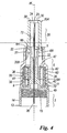
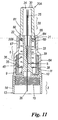
- a cylindrical protection element 20 is movable comprising a first end 20A external to said element 6 and a second end 20B internal to this latter.
- This second end 20B is flanged at 21 to cooperate with an internally bent edge 22 (bent towards the longitudinal axis W of the pen needle 1) of the end 6H of the cover element 6, to prevent complete withdrawal of the protector element 20 through the aperture 66 of the cover element 6.
- the protector element 20 On the outer edge of the first end 20A, the protector element 20 comprises a plurality of slightly pointed protuberances 30. These protuberances 30 make contact with the patient's skin to "mask" the sensation of pain by the injection and make this latter less painful.
- the cannula 5 is partially inserted into a tubular body 33 of the needle carrier 3 positioned along the axis W of the pen.
- a cylindrical container 35 in which a helical spring 36 is present, is positioned about said body 33, within a recess 34 of the first end 10 of the needle carrier 3 defined by the edge 11, and within the portion 6a of the cover element 6.
- the container 35 comprises a first hollow cylindrical portion or support 38 and a cover or second hollow cylindrical portion 39 snap-fitted to the first portion by coupling an inner collar 40 of the first portion (present on its wall 38A) to an annular seat 41 of the second portion formed inside a wall 39A thereof.
- This coupling enables a container 35 to be obtained which is independent of the rest of the components of the pen needle 1, and can also be preassembled with the corresponding spring 36.
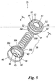
- the container 35 can be also assembled in any other known manner (for example by interference). With particular reference to Figures 5 and 6 , these show how the support 38, of cup shape and open at that end 38B facing the portion 39, has an aperture 43 within a base 44 to rest on the needle carrier 3.
- This aperture is defined by an annular portion 45 on which a first end 36A of the spring 36 rests.
- the second end 36B of this spring rests on a ring 47 positioned at a first end 46 of the cup-shaped second portion 39 of the container 35, which is open at its second end (that facing the second portion 38).
- This ring is present at an aperture 50 of said first end 46 and is coupled to the wall 39A of the portion 39 by breakable arms or bridges 52 of variable number and shape (for example, three in number as in the figures), but of small thickness.
- the container 35 can be preassembled with the internal spring 36 and mounted on the tubular body 33 of the needle carrier 3, this tubular body 33 being inserted into the aperture 43 and into the ring 47.
- the container 35 is coupled to the needle carrier 3 in the recess 34 by coupling thereto its collar 49, which projects from the portion 38 and cooperates with the recess 9 in the edge 11 of the end 10 of the needle carrier 3.
- These elements could also be coupled together in other ways known in the state of the art (for example by interference).
- the pen needle above cited therefore comprises various elements: the primary container 2, internally hollow at 2A, in which the needle carrier 3 is inserted, preassembled with the cannula 5 and container 35, and the cover element 6; into this latter, before assembling the needle carrier 3, the protector element 20 is inserted, the protuberances 30 of which, positioned on its first end 20A, rest against the closed end 2C of the container 2. In this manner, the protector element 20 becomes positioned correctly with respect to the cover element 6. In this respect, as the protector element 20 rests against the end 2C of the container 2, the assembly of the various parts 20, 6, 35, 3 of the pen needle bringing this protector element 20 into a position which is external to or projecting onto the cover element 6.
- the container 35 also snap-fits onto the cover element 6.
- the portion 39 of said container 35 presents an external annular recess 62 into which there projects a collar 63 provided on the inside of the portion 6A of the element 6.
- This connection between the container 35 and the element 6 can also be achieved in any other known manner, for example by interference.
- a removable closure paper 60 (or a seal of other material) closes the open or free end 2B of the container.
- the pen needle is used in the following manner.
- the movable protector element 20 begins to slide within the cover element 6, to expose the cannula 5 which can hence penetrate into the skin.
- the movable protector element 20 Before use, the movable protector element 20 remains in a fixed position because of its interference with the tapered portion 6H of the external cover element 6 and because of the cooperation between a number of ribs 72, present on the inside of the element 20, and the tubular body 33. In this manner, the movable protector element is unable to move unless sufficient pressure is applied thereto, and the cannula 5 remains hidden within the protector element.
- the ribs 72 of the protector element 20 interfere only with a first portion of the body 33 of the needle carrier 3, the pressure necessary to move the protector element 20 is minimal.
- the aforesaid interference is such as to maintain the protector element 20 in position prior to use, but not such as to hinder injection. Said protector element 20 can hence slide easily within the element 6, thus enabling the injection to be easily carried out.
- the lower end of the movable protector element 20 reaches the ring 47 of the cover element 6. Because of the small thickness of the arms 52 which connect it to the wall 39A of the portion 39, a light pressure applied to it (caused by the movement of the element 20) causes the arms to break.
- a weakening (not shown) of suitable shape can be provided on them.
- the ring 47 is no longer fixed to the cover element 6 and can be moved, urged by the movable protector element 20 against the spring 36.
- This spring hence compresses to enable the protector element 20 to proceed on its travel and enables the cannula 5 to penetrate completely into the patient's skin.
- the cannula can be extracted from the patient's body.
- the spring 36 extends to urge the movable protector element 20 to the outside of the cover element 6 through its end aperture.
- the spring 36 is free to extend completely and to urge the movable protector element beyond the cover element.
- the spring 36 pushes the protector element as far as a point in which an undercut 80 present in its outer surface 81 exceeds the free (tapered) end 6H of the cover element; in this manner the undercut abuts against that end, and the movable protector element is again unable to slide within the cover element.
- the flange 21 cooperating with this end 6H prevents the protector element from "withdrawing" from the element 6. Hence the cannula 5 cannot be exposed and the risk of accidental pricking and the possibility of reuse are nullified.
- the free end of the cover element has elastic arms 67 to give the end 6H greater elasticity.
- the spring 36 must evidently be of sufficient length to be able to snap-operate this safety mechanism irreversibly.
- a display element for example a coloured band
- its display indicates that the protector element has reached the safety protection position for the cannula 5.
- Apertures and windows 90 can also be provided close to the undercut to act as this display element.
- the inner surface of the movable protector element 20 does not present any ribs, whereas some ribs are present along the tubular body 33 of the needle carrier 3.
- the function of these ribs is identical to that of the ribs present on the aforedescribed movable protector element.
- the elongate body 33 comprises a collar 100 in proximity to its free end, said collar having an undercut 101 to cooperate with a corresponding abutment 102 present in proximity to the second end 20B, within the element 6, of the movable protector element 20 to block its exit from the container element 6 (urged by the spring 36).
- FIG. 15 , 16 and 17 A further embodiment of a pen needle, which is not part of the invention is shown in Figures 15 , 16 and 17 , in which parts corresponding to those of the already described figures are indicated by the same reference numerals.
- the elongate body 33 of the needle carrier 3 is of lesser length than the corresponding body of the other already described embodiments.
- This variant also has a different shape of undercut 80 of the movable protector element 20.
- the element is provided with a cavity 110 in which this undercut can move, and is flexible to achieve even simpler activation for the previously described irreversible safety mechanism.
- This element 20 interferes via its second end 20B with the external cover element 6 when in the initial rest position as this internal part has larger dimensions than the portion 6B of said element 6. This enables said initial position to be maintained when the needle 1 is not used.
- the elongate body 33 of the needle carrier 3 has the same length as that described in the aforedescribed Figures 15-17 .
- This variant also has a different shape for each undercut 80 present on the protector element 20.
- These undercuts are shaped as a cavity totally similar, in shape and function, as the already described cavity 110. With each cavity there interfere elastic arms 130 close to the internally bent edge 22 of the free end 6H of the cover element 6. This enables the safety position to be maintained after using the needle 1.
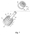
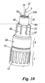
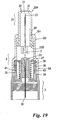
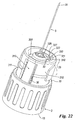
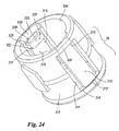
- FIGS. 20 to 25 show a pen needle according to the invention.
- the cylindrical container 35 is in one piece containing the spring 36 and a body 300 of substantially cylindrical shape.
- the body 300 has a collar 301 and an axial through bore 302 so that it can be disposed about the tubular body 33 of the needle carrier 3.
- the spring 36 is positioned between the collar 301 and the interior of the recess 34 at the end 10 needle carrier 3; this spring acts on said collar to press the body 300 in the direction of the protector element 20, i.e. towards that open end 35K of the container 35 which faces this latter.
- the body 300 In the condition prior to the use of the pen needle, the body 300 is inside the container 35 and is maintained therein by elastic arms 310 present in longitudinal slots (i.e. disposed along the axis W) 311 provided in the lateral part 312 of the container 35 defining the inner cavity of this latter. These arms 310 are secured at a first end 313 to a part 314 of the container 35 and have their second end 315 elastically movable relative to said wall 312 within the slots 311.
- Each arm 310 has its second end 315 shaped with an undercut.
- this end presents a portion 320 bent preferably (or substantially preferably) at an angle to the arm 310, to define with this latter the undercut 322, said portion having a free inclined surface part 323 facing towards the interior of the container 35.
- the end 315 terminates with a flat part 325 from which a tab 326 projects above the arm 315 in its longitudinal direction, and has a right-angled triangular cross-section (or other equivalent form) with its inclined side 327 facing outwards from the container.
- the tab 326 is arranged to cooperate with a bridge 330 which closes the corresponding slot 311 above the arm 310.
- This bridge maintains the arm 310 in its condition bent towards the outside of the container 35 after the protector element 20 has cooperated therewith on re-entering the cover element 6. This cooperation takes place between the end 20B of the element 20, flared inwards towards the axis W of Figure 21 , and the portion 320 of each arm when the element 20 re-enters the element 6.
- the arms 310 cooperate with the collar 301 of the body 300 to retain it inside the container 35.
- the cooperation between said arms 20 and the collar results in compression of the spring 36.
- the element 20 When the needle penetrates the patient's body, the element 20 re-enters the cover element 6 (in the described manner) until its end 20B contacts the inclined surface 323 of each arm 310. At this point, the sliding of said end along said inclined surfaces 323 causes the arms 310 to withdraw from the axis W of the pen needle; this withdrawal causes the tabs 326 of said arms to slide, via their inclined side 327, on the corresponding bridge 330 with consequent deformation of the relative arms, so that each tab 326 overcomes said bridge. It follows that the tab abuts on the relative bridge after overcoming this latter, with consequent locking of the relative arm in a position spaced from the axis W (see Figure 25 ).
- the element 20 comes into contact with the body 300, to move it within the cylindrical container 35 towards the needle carrier 3. This results in compression of the spring 36.
- the removal of the needle 5 from the patient with withdrawal of the element 6 from the patient's body enables the element 20 to move relative to said element 6, this latter making its withdrawal movement under the thrust of the spring 36.
- this latter acts on the collar 301 of the body 300 and hence by urging this latter out of the container 35 (as it is no longer retained by the arm 310) it causes said element 6 to thrust the element 20 (resting on the body 300) to the outside.
- This movement results in the element 20 becoming superposed on the needle 5 to protect a medical operator or the user against contact with the first end or "patient point" thereof.
- the withdrawal movement of the protector element 20 terminates, as in the other embodiments of the pen needle which are not part of the present invention described in figures 1 to 19 , by it resting its end 20A on the edge 22 of the element 6.
Claims (11)
- Stiftnadel, die an einen Behälter oder Stift anzuschließen ist, zu dem eine Ampulle mit Medikament gehört, wobei die Nadel (1) aufweist:eine Metallkanüle (5), die mit zwei Spitzen (25, 26), einer an jedem Ende, versehen ist, wobei die erste (25), die als "Patientenspitze" bekannt ist, den Zweck hat, die Epidermis zu schneiden, um zu ermöglichen, dass die Kanüle (5) in die Haut des Patienten eingeführt wird, und die zweite (26), die sich innen an einem Nadelträger (3) befindet und als "Ampullenspitze" bekannt ist, den Zweck hat, die medizinische Ampulle zu durchstechen, wenn die Stiftnadel (1) am Stift befestigt wird, wodurch ermöglicht wird, dass das Medikament während der tatsächlichen Injektion von der Ampulle über die Kanüle (5) zu einem Patienten übertragen wird;den vorgenannten Nadelträger (3), der mit dem Stift zu verbinden ist;einen primären Behälter (2), der den Zweck hat, die gesamte Stiftnadel (1) vor dem Gebrauch aufzunehmen;ein Abdeckelement (6), das mit dem Nadelträger (3) verbunden und um die Kanüle (5) herum positioniert ist;ein Schutzelement (20), das innerhalb des Abdeckelements (6) bewegbar und so angeordnet ist, dass es aus letzterem herausragt, um die erste Spitze der Kanüle (5) nach deren Herausziehen aus dem Patienten bei Beendigung der Injektion abzudecken, um einen versehentlichen Kontakt mit der Spitze (25) durch eine Person, die die Injektion durchführt, oder durch den Patienten selbst zu vermeiden, und um eine Wiederverwendung der Vorrichtung zu verhindern;ein elastisches Element (36), das angeordnet ist, um auf das Schutzelement (20) zu drücken, um zu ermöglichen, dass es sich bei Beendigung der Injektion und während des Herausziehens der Kanüle (5) aus dem Patienten bewegt, wobei die Bewegung verursacht, dass das Element die erste Spitze (25) der Kanüle (5) abdeckt, wobei Blockiermittel (47, 300, 310) für das elastische Element (36) vorgesehen sind, um seine Aktion auf das Schutzelement (20) zu verhindern, zumindest bis zu einem Zeitpunkt nach dem Beginn des Einführens der Kanüle (5) in die Epidermis, wobei die Blockiermittel (47, 300, 310) nach dem Zeitpunkt, in dem das Einführen begann, entfernbar sind,dadurch gekennzeichnet, dass
das Schutzelement (20) ein erstes Ende (20A) aufweist, das sich außerhalb des Abdeckelements (6) befindet, und ein zweites Ende (20B), das sich innerhalb des letzteren befindet, wobei das Schutzelement (20) wesentlich vom Abdeckelement (6) vorsteht und die Kanüle (5) abdeckt, wenn der Nadelstift einsatzbereit ist (Figur 2, 4), wobei sich das erste Ende (20A) auf der Haut des Patienten befindet, wenn eine Person mit der Injektion beginnt, wobei das Schutzelement (20) innerhalb des Abdeckelements (6) leicht gleitet, um die Kanüle (5) freizulegen, welche somit in die Haut eindringt, bis das zweite Ende (20B) des Schutzes die Blockiermittel kontaktiert, wobei die Blockiermittel (300, 310) entfernt werden, wenn die Nadel in den Körper des Patienten eindringt und das Schutzelement (20) in das Abdeckelement (6) eintritt, wobei die Bewegung dazu führt, dass das elastische Element (36) komprimiert wird, so dass, wenn die Injektion beendet ist, das Entfernen der Nadel (5) aus dem Patienten ermöglicht, dass sich das Schutzelement (20) aufgrund des elastischen Elements (36) relativ zu dem Abdeckelement (6) bewegt, wodurch sich das Schutzelement aus dem Abdeckelement herausbewegt und die Kanüle (5) überlagert. - Stiftnadel nach Anspruch 1, dadurch gekennzeichnet, dass die Blockiermittel ein innen hohles Behälterelement (35) aufweisen, das wenigstens ein Element (310) aufweist, das in einem entsprechenden Sitz (311), der in einer Wand (312) des Behälterkörpers (35) vorgesehen ist und den inneren Hohlraum des Letzteren definiert, elastisch beweglich ist, wobei das bewegliche Element (310) ein Element zum Blockieren der Bewegung eines Körpers (300) definiert, mit dem ein zweites Ende (36B) des elastischen Elements (36) zusammenwirkt, wobei das bewegliche Blockierelement (310) mit dem Schutzelement (20) zusammenwirkt, wenn es im Abdeckelement (6) positioniert ist, um den Körper (300), der mit dem elastischen Element zusammenwirkt, freizusetzen und zu ermöglichen, dass Letzteres auf den Körper (300) Kraft ausübt, mit einer Folgeaktion des Letzteren auf das Schutzelement, um es an die Außenseite des Abdeckelements (6) zu bewegen und um die erste Spitze oder Patientenspitze (26) der Kanüle (5) herum zu positionieren.
- Stiftnadel nach Anspruch 2, dadurch gekennzeichnet, dass der Körper (300) einen Kragen (301) aufweist, mit dem das zweite Ende (36B) des elastischen Elements (36) zusammenwirkt, wobei sich ein erstes Ende (36A) des elastischen Elements (36) im Behälterkörper (35) befindet und an ihm anliegt, wobei das wenigstens eine bewegliche Element (310) ein Arm ist, der an seinem ersten Ende (313) mit dem Behälterkörper (35) verbunden ist und ein zweites Ende (315) aufweist, das in dem entsprechenden Sitz (311), der in der Wand (312) des Behälterkörpers vorgesehen ist, frei angeordnet ist, wobei das zweite Ende einen Abschnitt (320) aufweist, der winkelig in Richtung des Inneren des Behälterkörpers (35) relativ zu dem entsprechenden Arm (310) gebogen ist und mit Letzterem eine Unterschneidung (322) definiert, die ausgelegt ist, um auf dem Kragen (301) des Körpers (300) aufzuliegen, der mit dem elastischen Element (36) zusammenwirkt, wobei der gebogene Abschnitt (320) eine geneigte Oberfläche (323) aufweist, die sich in Richtung des Inneren des Behälterkörpers (35) verjüngt und mit einem verjüngten Ende (20B) des Schutzelements (20) im Abdeckelement (6) gleitend zusammenwirkt, wobei dieses Zusammenwirken stattfindet, während das Schutzelement (20) wieder in Letzteres eintritt, was zu einer Bewegung des Arms (310) vom Körper (300) weg und zum Freigeben des Letzteren führt, wobei diese Bewegung von der Längsachse (W) der Stiftnadel weg stattfindet.
- Stiftnadel nach Anspruch 3, dadurch gekennzeichnet, dass das zweite Ende (315) des Arms (310) oben einen Vorsprung mit dem Querschnitt eines rechtwinkligen Dreiecks stützt, wobei die geneigte Seite (327) vom Behälterkörper (35) nach außen zeigt, wobei der Vorsprung (326) mit einem Verschlusselement (330) für den Sitz (311), in dem der Arm (310) elastisch bewegbar ist, zusammenwirkt, wobei dieses Verschlusselement nahe dem Ende (315) des Letzteren angeordnet und dazu ausgelegt ist, den Arm (310) in der Position vom Körper (300) entfernt, durch Zusammenwirken mit dem elastischen Element nach seinem Zusammenwirken mit dem Vorsprung (326) festzulegen.
- Stiftnadel nach Anspruch 2, dadurch gekennzeichnet, dass der Behälterkörper (35) um einen rohrförmigen Körper (33), der starr mit dem Nadelträger (3) ist und die durchgehende Kanüle (5) enthält, angeordnet ist.
- Stiftnadel nach Anspruch 1, dadurch gekennzeichnet, dass das Schutzelement (20) zu Beginn einer Injektion vom Behälterkörper (35) abgenommen wird und in seine Nähe reicht, nachdem die Kanüle (5) die Epidermis des Patienten durchstochen hat, wobei sich das Schutzelement (20) von einem freien Ende (6H) des Abdeckelements (6) in Richtung des Nadelträgers (3) bewegt, wobei die Bewegung des Schutzelements in Richtung des Nadelträgers (3) nach dem Kontakt mit dem Behälterkörper (35) andauert, um die Blockiermittel (300, 310) zu entfernen und das elastische Element (36) im Behälterkörper (35) zusammenzudrücken.
- Stiftnadel nach Anspruch 1, gekennzeichnet durch Bereitstellen einer stabilen Position außerhalb des Abdeckelements (6), die durch das Schutzelement (20) erzielt wird, wenn von dem elastischen Element (36) beim Herausziehen der Kanüle (5) aus dem Patienten darauf Kraft ausgeübt wird, wobei Mittel (21, 80, 101) zum stabilen Festlegen des Schutzelements (20) am freien Ende (6H) des Abdeckelements (6) vorgesehen sind.
- Stiftnadel nach Anspruch 7, dadurch gekennzeichnet, dass die Blockiermittel ein Flansch (21) sind, der sich am zweiten Ende (20B) des Schutzelements (20) befindet, um mit einer Kante (22) des freien Endes (6H) innerhalb des Abdeckelements (6) zusammenzuwirken.
- Stiftnadel nach Anspruch 7, dadurch gekennzeichnet, dass die Blockiermittel wenigstens eine Unterschneidung (80) sind, die sich auf einer Außenfläche (81) des Schutzelements (20) befindet und mit dem freien Ende (6H) des Abdeckelements (6) zusammenwirkt.
- Stiftnadel nach Anspruch 7, dadurch gekennzeichnet, dass die Blockiermittel ein Kragen (100) sind, der sich auf dem rohrförmigen Körper (33) der Stiftnadel (1) befindet und mit einer Unterschneidung (101) versehen ist, wobei die Unterschneidung mit einem korrespondierenden Anschlag (102) zusammenwirkt, der sich in der Nähe des zweiten Endes (20B) des beweglichen Schutzelements (20) befindet.
- Stiftnadel nach Anspruch 1, dadurch gekennzeichnet, dass das Schutzelement (20) an seinem ersten Ende (20A) eine Vielzahl von bevorzugt leicht zugespitzten Vorsprüngen (30) aufweist.
Priority Applications (3)
| Application Number | Priority Date | Filing Date | Title |
|---|---|---|---|
| SI200930796T SI2090326T1 (sl) | 2008-02-13 | 2009-02-12 | Varnostna igla za injekcijski peresnik z varovalom za iglo |
| PL09152685T PL2090326T3 (pl) | 2008-02-13 | 2009-02-12 | Bezpieczna igła do wstrzykiwacza piórowego z elementem zabezpieczającym kaniulę |
| CY20131101134T CY1115335T1 (el) | 2008-02-13 | 2013-12-17 | Βελονα ασφαλειας για συσκευη τυπου πενας με προστατευτικο στοιχειο καθετηρα |
Applications Claiming Priority (1)
| Application Number | Priority Date | Filing Date | Title |
|---|---|---|---|
| IT000218A ITMI20080218A1 (it) | 2008-02-13 | 2008-02-13 | Ago penna di sicurezza con elemento protettore per la cannula |
Publications (2)
| Publication Number | Publication Date |
|---|---|
| EP2090326A1 EP2090326A1 (de) | 2009-08-19 |
| EP2090326B1 true EP2090326B1 (de) | 2013-09-18 |
Family
ID=40291629
Family Applications (1)
| Application Number | Title | Priority Date | Filing Date |
|---|---|---|---|
| EP09152685.5A Active EP2090326B1 (de) | 2008-02-13 | 2009-02-12 | Sicherheits-Injektionsstiftnadel mit Schutzelement für die Nadel |
Country Status (9)
| Country | Link |
|---|---|
| EP (1) | EP2090326B1 (de) |
| CY (1) | CY1115335T1 (de) |
| DK (1) | DK2090326T3 (de) |
| ES (1) | ES2439707T3 (de) |
| HR (1) | HRP20131126T1 (de) |
| IT (1) | ITMI20080218A1 (de) |
| PL (1) | PL2090326T3 (de) |
| PT (1) | PT2090326E (de) |
| SI (1) | SI2090326T1 (de) |
Cited By (3)
| Publication number | Priority date | Publication date | Assignee | Title |
|---|---|---|---|---|
| USD768852S1 (en) | 2014-06-30 | 2016-10-11 | Htl-Strefa Spolka Akcyjna | Safety needle device |
| USD768851S1 (en) | 2014-06-30 | 2016-10-11 | Htl-Strefa Spolka Akcyjna | Safety needle device |
| WO2022261458A1 (en) * | 2021-06-11 | 2022-12-15 | Embecta Corp. | Pen needle assembly |
Families Citing this family (16)
| Publication number | Priority date | Publication date | Assignee | Title |
|---|---|---|---|---|
| US7811261B2 (en) | 2008-06-02 | 2010-10-12 | Sta-Med, Llc | Needle cover assembly for a syringe |
| WO2011140596A1 (en) * | 2010-05-11 | 2011-11-17 | Noble House Group Pty. Ltd. | Medical sampling port |
| US8162882B2 (en) | 2010-06-23 | 2012-04-24 | Sta-Med, Llc | Automatic-locking safety needle covers and methods of use and manufacture |
| AU2011354198B2 (en) * | 2011-01-04 | 2015-10-22 | Sanofi-Aventis Deutschland Gmbh | A safety device for a pre-filled syringe and an injection device |
| US8961470B2 (en) | 2011-02-17 | 2015-02-24 | Steven Schraga | Pen needle with safety shield system |
| WO2012166746A1 (en) | 2011-05-31 | 2012-12-06 | Sta-Med, Llc | Blood collection safety devices and methods of use and manufacture |
| SK500122012A3 (sk) * | 2012-03-28 | 2013-10-02 | Marian Buday | Single-use safety syringe |
| PL234202B1 (pl) | 2013-09-30 | 2020-01-31 | Htl Strefa Spolka Akcyjna | Urządzenie igły bezpiecznej |
| US10118000B2 (en) | 2014-04-21 | 2018-11-06 | Stat Medical Devices, Inc. | Pen needle installation and removal safety cover and pen needle assembly utilizing the same |
| US10155091B2 (en) | 2014-07-11 | 2018-12-18 | Stat Medical Devices, Inc. | Pen needle tip and method of making and using the same |
| CN204219537U (zh) * | 2014-11-04 | 2015-03-25 | 温州市贝普科技有限公司 | 一次性使用安全自毁胰岛素针 |
| JP2018512184A (ja) | 2015-02-27 | 2018-05-17 | アムジエン・インコーポレーテツド | 針ガードの移動に対する抵抗力の閾値が調整可能な針ガード機構を備えた薬物送達装置 |
| WO2018107231A1 (en) * | 2016-12-14 | 2018-06-21 | Edyson Pty Ltd | A needle screening device |
| CN109847151A (zh) * | 2018-12-27 | 2019-06-07 | 宁波美生医疗器材有限公司 | 一种安全型注射装置、注射器及其组装方法 |
| CN110141733B (zh) * | 2019-05-10 | 2023-06-30 | 山东连发医用塑胶制品有限公司 | 一种安全胰岛素注射针头 |
| CN111420168B (zh) * | 2020-04-01 | 2022-03-01 | 山西医科大学第一医院 | 静脉注射装置 |
Family Cites Families (5)
| Publication number | Priority date | Publication date | Assignee | Title |
|---|---|---|---|---|
| US6432087B1 (en) * | 2000-07-31 | 2002-08-13 | Becton, Dickinson And Company | Hypodermic syringe with selectively retractable needle |
| US6986760B2 (en) | 2000-08-02 | 2006-01-17 | Becton, Dickinson And Company | Pen needle and safety shield system |
| KR100879498B1 (ko) | 2001-11-30 | 2009-01-20 | 노보 노르디스크 에이/에스 | 안전 바늘 조립체 |
| US7101351B2 (en) * | 2003-11-03 | 2006-09-05 | Becton, Dickinson And Company | Safety device for a syringe |
| US20050277897A1 (en) | 2004-06-14 | 2005-12-15 | Ghannoum Ziad R | Handpiece tip |
-
2008
- 2008-02-13 IT IT000218A patent/ITMI20080218A1/it unknown
-
2009
- 2009-02-12 SI SI200930796T patent/SI2090326T1/sl unknown
- 2009-02-12 ES ES09152685.5T patent/ES2439707T3/es active Active
- 2009-02-12 EP EP09152685.5A patent/EP2090326B1/de active Active
- 2009-02-12 PT PT91526855T patent/PT2090326E/pt unknown
- 2009-02-12 DK DK09152685.5T patent/DK2090326T3/da active
- 2009-02-12 PL PL09152685T patent/PL2090326T3/pl unknown
-
2013
- 2013-11-25 HR HRP20131126AT patent/HRP20131126T1/hr unknown
- 2013-12-17 CY CY20131101134T patent/CY1115335T1/el unknown
Cited By (3)
| Publication number | Priority date | Publication date | Assignee | Title |
|---|---|---|---|---|
| USD768852S1 (en) | 2014-06-30 | 2016-10-11 | Htl-Strefa Spolka Akcyjna | Safety needle device |
| USD768851S1 (en) | 2014-06-30 | 2016-10-11 | Htl-Strefa Spolka Akcyjna | Safety needle device |
| WO2022261458A1 (en) * | 2021-06-11 | 2022-12-15 | Embecta Corp. | Pen needle assembly |
Also Published As
| Publication number | Publication date |
|---|---|
| DK2090326T3 (da) | 2013-12-09 |
| HRP20131126T1 (hr) | 2014-01-03 |
| ES2439707T3 (es) | 2014-01-24 |
| EP2090326A1 (de) | 2009-08-19 |
| ITMI20080218A1 (it) | 2009-08-14 |
| PL2090326T3 (pl) | 2014-02-28 |
| SI2090326T1 (sl) | 2014-01-31 |
| PT2090326E (pt) | 2013-12-10 |
| CY1115335T1 (el) | 2017-01-04 |
Similar Documents
| Publication | Publication Date | Title |
|---|---|---|
| EP2090326B1 (de) | Sicherheits-Injektionsstiftnadel mit Schutzelement für die Nadel | |
| JP2959638B2 (ja) | 自動注射器 | |
| US9579467B2 (en) | Safety pen needle device | |
| US6846302B2 (en) | Needle protector device | |
| US8357125B2 (en) | Autoinjector with deactivating means moveable by a safety shield | |
| JP5849360B2 (ja) | 医療用針安全装置 | |
| EP2566541B1 (de) | Verlängerter fingergriff für spritzensysteme | |
| CN107405460B (zh) | 设置有安全保护系统的笔针 | |
| JP2010540059A (ja) | 安全シールドによって非活動化することができる容器保持手段を備える自動注射装置 | |
| US20150217062A1 (en) | Needle assembly removal device | |
| CN219050059U (zh) | 带有防针刺功能的药剂输送装置 | |
| US11097068B2 (en) | Safety needle with deformable cannula for injector pen | |
| KR20200130247A (ko) | 주사기 및 보호 조립체를 포함하는 주입 시스템 | |
| CN116710162A (zh) | 具有枢转针防护装置的低死腔注射器 | |
| KR20190039737A (ko) | 안전 하우징 기반 이식물/약제 주입 시스템 | |
| CN213252098U (zh) | 笔针 | |
| US20170326305A1 (en) | Needle Assembly with Needle Hub Shielding a Needle Cannula | |
| CN217311431U (zh) | 一种安全注射器及其安全注射针头 | |
| WO2022079576A1 (en) | Sub-assembly of needle non-injection end passive sheath and safety pen needle assembly | |
| WO2018215605A1 (en) | System for safe handling of medical needle unit |
Legal Events
| Date | Code | Title | Description |
|---|---|---|---|
| PUAI | Public reference made under article 153(3) epc to a published international application that has entered the european phase |
Free format text: ORIGINAL CODE: 0009012 |
|
| AK | Designated contracting states |
Kind code of ref document: A1 Designated state(s): AT BE BG CH CY CZ DE DK EE ES FI FR GB GR HR HU IE IS IT LI LT LU LV MC MK MT NL NO PL PT RO SE SI SK TR |
|
| AX | Request for extension of the european patent |
Extension state: AL BA RS |
|
| 17P | Request for examination filed |
Effective date: 20100216 |
|
| AKX | Designation fees paid |
Designated state(s): AT BE BG CH CY CZ DE DK EE ES FI FR GB GR HR HU IE IS IT LI LT LU LV MC MK MT NL NO PL PT RO SE SI SK TR |
|
| 17Q | First examination report despatched |
Effective date: 20101201 |
|
| GRAP | Despatch of communication of intention to grant a patent |
Free format text: ORIGINAL CODE: EPIDOSNIGR1 |
|
| INTG | Intention to grant announced |
Effective date: 20130528 |
|
| GRAS | Grant fee paid |
Free format text: ORIGINAL CODE: EPIDOSNIGR3 |
|
| GRAA | (expected) grant |
Free format text: ORIGINAL CODE: 0009210 |
|
| AK | Designated contracting states |
Kind code of ref document: B1 Designated state(s): AT BE BG CH CY CZ DE DK EE ES FI FR GB GR HR HU IE IS IT LI LT LU LV MC MK MT NL NO PL PT RO SE SI SK TR |
|
| REG | Reference to a national code |
Ref country code: GB Ref legal event code: FG4D |
|
| REG | Reference to a national code |
Ref country code: CH Ref legal event code: EP |
|
| REG | Reference to a national code |
Ref country code: IE Ref legal event code: FG4D |
|
| REG | Reference to a national code |
Ref country code: AT Ref legal event code: REF Ref document number: 632399 Country of ref document: AT Kind code of ref document: T Effective date: 20131015 |
|
| REG | Reference to a national code |
Ref country code: DE Ref legal event code: R096 Ref document number: 602009018831 Country of ref document: DE Effective date: 20131114 |
|
| REG | Reference to a national code |
Ref country code: CH Ref legal event code: PCOW Ref country code: CH Ref legal event code: NV Representative=s name: R. A. EGLI AND CO. PATENTANWAELTE, CH |
|
| REG | Reference to a national code |
Ref country code: HR Ref legal event code: TUEP Ref document number: P20131126 Country of ref document: HR |
|
| REG | Reference to a national code |
Ref country code: DK Ref legal event code: T3 Effective date: 20131204 Ref country code: RO Ref legal event code: EPE |
|
| REG | Reference to a national code |
Ref country code: PT Ref legal event code: SC4A Free format text: AVAILABILITY OF NATIONAL TRANSLATION Effective date: 20131203 |
|
| REG | Reference to a national code |
Ref country code: SE Ref legal event code: TRGR |
|
| REG | Reference to a national code |
Ref country code: NL Ref legal event code: T3 |
|
| REG | Reference to a national code |
Ref country code: HR Ref legal event code: T1PR Ref document number: P20131126 Country of ref document: HR |
|
| REG | Reference to a national code |
Ref country code: ES Ref legal event code: FG2A Ref document number: 2439707 Country of ref document: ES Kind code of ref document: T3 Effective date: 20140124 |
|
| REG | Reference to a national code |
Ref country code: NO Ref legal event code: T2 Effective date: 20130918 |
|
| REG | Reference to a national code |
Ref country code: EE Ref legal event code: FG4A Ref document number: E008680 Country of ref document: EE Effective date: 20131125 |
|
| REG | Reference to a national code |
Ref country code: GR Ref legal event code: EP Ref document number: 20130402650 Country of ref document: GR Effective date: 20140124 |
|
| REG | Reference to a national code |
Ref country code: PL Ref legal event code: T3 |
|
| REG | Reference to a national code |
Ref country code: SK Ref legal event code: T3 Ref document number: E 15803 Country of ref document: SK |
|
| REG | Reference to a national code |
Ref country code: DE Ref legal event code: R097 Ref document number: 602009018831 Country of ref document: DE |
|
| PLBE | No opposition filed within time limit |
Free format text: ORIGINAL CODE: 0009261 |
|
| STAA | Information on the status of an ep patent application or granted ep patent |
Free format text: STATUS: NO OPPOSITION FILED WITHIN TIME LIMIT |
|
| 26N | No opposition filed |
Effective date: 20140619 |
|
| REG | Reference to a national code |
Ref country code: DE Ref legal event code: R097 Ref document number: 602009018831 Country of ref document: DE Effective date: 20140619 |
|
| REG | Reference to a national code |
Ref country code: HU Ref legal event code: AG4A Ref document number: E020601 Country of ref document: HU |
|
| REG | Reference to a national code |
Ref country code: FR Ref legal event code: PLFP Year of fee payment: 7 |
|
| REG | Reference to a national code |
Ref country code: FR Ref legal event code: PLFP Year of fee payment: 8 |
|
| REG | Reference to a national code |
Ref country code: FR Ref legal event code: PLFP Year of fee payment: 9 |
|
| REG | Reference to a national code |
Ref country code: FR Ref legal event code: PLFP Year of fee payment: 10 |
|
| REG | Reference to a national code |
Ref country code: ES Ref legal event code: PC2A Owner name: PIKDARE S.R.L. Effective date: 20180403 |
|
| REG | Reference to a national code |
Ref country code: CH Ref legal event code: PUE Owner name: PIKDARE S.R.L., IT Free format text: FORMER OWNER: ARTSANA S.P.A., IT Ref country code: CH Ref legal event code: NV Representative=s name: R.A. EGLI AND CO, PATENTANWAELTE, CH |
|
| REG | Reference to a national code |
Ref country code: EE Ref legal event code: GB1A Ref document number: E008680 Country of ref document: EE |
|
| REG | Reference to a national code |
Ref country code: GB Ref legal event code: 732E Free format text: REGISTERED BETWEEN 20180426 AND 20180502 |
|
| REG | Reference to a national code |
Ref country code: SK Ref legal event code: PC4A Ref document number: E 15803 Country of ref document: SK Owner name: PIKDARE S.R.L., CASNATE CON BERNATE (CO), IT Free format text: FORMER OWNER: ARTSANA S.P.A., GRANDATE (COMO), IT Effective date: 20180423 |
|
| REG | Reference to a national code |
Ref country code: DE Ref legal event code: R082 Ref document number: 602009018831 Country of ref document: DE Representative=s name: KRAUS & WEISERT PATENTANWAELTE PARTGMBB, DE Ref country code: DE Ref legal event code: R081 Ref document number: 602009018831 Country of ref document: DE Owner name: PIKDARE-SOCIETA PER AZIONI, IT Free format text: FORMER OWNER: ARTSANA S.P.A., GRANDATE, COMO, IT Ref country code: DE Ref legal event code: R081 Ref document number: 602009018831 Country of ref document: DE Owner name: PIKDARE S.R.L., CASNATE CON BERNATE, IT Free format text: FORMER OWNER: ARTSANA S.P.A., GRANDATE, COMO, IT Ref country code: DE Ref legal event code: R081 Ref document number: 602009018831 Country of ref document: DE Owner name: PIKDARE S.R.L., IT Free format text: FORMER OWNER: ARTSANA S.P.A., GRANDATE, COMO, IT |
|
| REG | Reference to a national code |
Ref country code: LU Ref legal event code: PD Owner name: PIDKARE S.R.L.; IT Free format text: FORMER OWNER: ARTSANA S.P.A. Effective date: 20180502 |
|
| REG | Reference to a national code |
Ref country code: NL Ref legal event code: PD Owner name: PIKDARE S.R.L.; IT Free format text: DETAILS ASSIGNMENT: CHANGE OF OWNER(S), ASSIGNMENT; FORMER OWNER NAME: ARTSANA S.P.A. Effective date: 20180629 |
|
| REG | Reference to a national code |
Ref country code: HR Ref legal event code: PPPP Ref document number: P20131126 Country of ref document: HR Owner name: PIKDARE S.R.L., IT |
|
| REG | Reference to a national code |
Ref country code: BE Ref legal event code: PD Owner name: PIKDARE S.R.L.; IT Free format text: DETAILS ASSIGNMENT: CHANGE OF OWNER(S), CESSION; FORMER OWNER NAME: ARTSANA S.P.A. Effective date: 20180426 |
|
| REG | Reference to a national code |
Ref country code: NO Ref legal event code: CREP Representative=s name: TANDBERG INNOVATION AS, POSTBOKS 1570 VIKA, 0118 Ref country code: NO Ref legal event code: CHAD Owner name: PIKDARE S.R.L., IT |
|
| REG | Reference to a national code |
Ref country code: HU Ref legal event code: GB9C Owner name: PIKDARE S.R.L., IT Free format text: FORMER OWNER(S): ARTSANA S.P.A., IT Ref country code: HU Ref legal event code: FH1C Free format text: FORMER REPRESENTATIVE(S): MESZAROSNE DONUSZ KATALIN, SBGK SZABADALMI UEGYVIVOEI IRODA, HU Representative=s name: SBGK SZABADALMI UEGYVIVOEI IRODA, HU |
|
| REG | Reference to a national code |
Ref country code: SI Ref legal event code: SP73 Owner name: PIKDARE S.R.L.; IT Effective date: 20180612 |
|
| REG | Reference to a national code |
Ref country code: AT Ref legal event code: PC Ref document number: 632399 Country of ref document: AT Kind code of ref document: T Owner name: PIKDARE S.R.L., IT Effective date: 20180716 |
|
| REG | Reference to a national code |
Ref country code: FR Ref legal event code: TP Owner name: PIKDARE S.R.L., IT Effective date: 20180919 |
|
| REG | Reference to a national code |
Ref country code: HR Ref legal event code: ODRP Ref document number: P20131126 Country of ref document: HR Payment date: 20190206 Year of fee payment: 11 |
|
| REG | Reference to a national code |
Ref country code: HR Ref legal event code: ODRP Ref document number: P20131126 Country of ref document: HR Payment date: 20200206 Year of fee payment: 12 |
|
| REG | Reference to a national code |
Ref country code: DE Ref legal event code: R082 Ref document number: 602009018831 Country of ref document: DE Representative=s name: KRAUS & WEISERT PATENTANWAELTE PARTGMBB, DE Ref country code: DE Ref legal event code: R081 Ref document number: 602009018831 Country of ref document: DE Owner name: PIKDARE-SOCIETA PER AZIONI, IT Free format text: FORMER OWNER: PIKDARE S.R.L., CASNATE CON BERNATE, COMO, IT Ref country code: NO Ref legal event code: CHAD Owner name: PIKDARE-SOCIETA PER AZIONI, IT |
|
| REG | Reference to a national code |
Ref country code: NL Ref legal event code: PD Owner name: PIKDARE-SOCIETA' PER AZIONI; IT Free format text: DETAILS ASSIGNMENT: CHANGE OF OWNER(S), CHANGE OF LEGAL ENTITY; FORMER OWNER NAME: PIKDARE S.R.L. Effective date: 20200331 |
|
| REG | Reference to a national code |
Ref country code: LU Ref legal event code: HC Owner name: PIDKARE-SOCIETA PER AZIONI; IT Free format text: FORMER OWNER: PIDKARE S.R.L. Effective date: 20200320 |
|
| REG | Reference to a national code |
Ref country code: EE Ref legal event code: HC1A Ref document number: E008680 Country of ref document: EE |
|
| REG | Reference to a national code |
Ref country code: BE Ref legal event code: HC Owner name: PIKDARE-SOCIETA PER AZIONI; IT Free format text: DETAILS ASSIGNMENT: CHANGE OF OWNER(S), CHANGEMENT DE NOM DU PROPRIETAIRE; FORMER OWNER NAME: PIKDARE S.R.L. Effective date: 20200317 |
|
| REG | Reference to a national code |
Ref country code: HR Ref legal event code: PNAN Ref document number: P20131126 Country of ref document: HR Owner name: PIKDARE- SOCIETA PER AZIONI, IT |
|
| REG | Reference to a national code |
Ref country code: FI Ref legal event code: PCE Owner name: PIKDARE-SOCIETAA PER AZIONI |
|
| REG | Reference to a national code |
Ref country code: CH Ref legal event code: PFA Owner name: PIKDARE - SOCIETA PER AZIONI, IT Free format text: FORMER OWNER: PIKDARE S.R.L., IT |
|
| REG | Reference to a national code |
Ref country code: SK Ref legal event code: TC4A Ref document number: E 15803 Country of ref document: SK Owner name: PIKDARE-SOCIETA PER AZIONI, CASNATE CON BERNAT, IT Effective date: 20200701 |
|
| REG | Reference to a national code |
Ref country code: AT Ref legal event code: HC Ref document number: 632399 Country of ref document: AT Kind code of ref document: T Owner name: PIKDARE-SOCIETA PER AZIONI, IT Effective date: 20200624 |
|
| REG | Reference to a national code |
Ref country code: HU Ref legal event code: GB9C Owner name: PIKDARE-SOCIETA PER AZIONI, IT Free format text: FORMER OWNER(S): ARTSANA S.P.A., IT; PIKDARE S.R.L., IT Ref country code: HU Ref legal event code: FH1C Free format text: FORMER REPRESENTATIVE(S): SBGK SZABADALMI UEGYVIVOEI IRODA, HU Representative=s name: DR. KOCSOMBA NELLI UEGYVEDI IRODA, HU |
|
| REG | Reference to a national code |
Ref country code: HU Ref legal event code: HC9C Owner name: PIKDARE-SOCIETA PER AZIONI, IT Free format text: FORMER OWNER(S): ARTSANA S.P.A., IT; PIKDARE S.R.L., IT |
|
| REG | Reference to a national code |
Ref country code: HR Ref legal event code: ODRP Ref document number: P20131126 Country of ref document: HR Payment date: 20210205 Year of fee payment: 13 |
|
| REG | Reference to a national code |
Ref country code: HR Ref legal event code: ODRP Ref document number: P20131126 Country of ref document: HR Payment date: 20220207 Year of fee payment: 14 |
|
| PGFP | Annual fee paid to national office [announced via postgrant information from national office to epo] |
Ref country code: MK Payment date: 20220208 Year of fee payment: 14 |
|
| REG | Reference to a national code |
Ref country code: HU Ref legal event code: HC9C Owner name: PIKDARE-SOCIETA PER AZIONI, IT Free format text: FORMER OWNER(S): ARTSANA S.P.A., IT; PIKDARE S.R.L., IT |
|
| REG | Reference to a national code |
Ref country code: ES Ref legal event code: PC2A Owner name: PIKDARE-SOCIETA' PER AZIONI Effective date: 20221116 |
|
| REG | Reference to a national code |
Ref country code: HR Ref legal event code: ODRP Ref document number: P20131126 Country of ref document: HR Payment date: 20230207 Year of fee payment: 15 |
|
| PGFP | Annual fee paid to national office [announced via postgrant information from national office to epo] |
Ref country code: NL Payment date: 20230216 Year of fee payment: 15 |
|
| PGFP | Annual fee paid to national office [announced via postgrant information from national office to epo] |
Ref country code: RO Payment date: 20230203 Year of fee payment: 15 Ref country code: NO Payment date: 20230220 Year of fee payment: 15 Ref country code: MC Payment date: 20230220 Year of fee payment: 15 Ref country code: LU Payment date: 20230220 Year of fee payment: 15 Ref country code: LT Payment date: 20230206 Year of fee payment: 15 Ref country code: IE Payment date: 20230217 Year of fee payment: 15 Ref country code: FR Payment date: 20230220 Year of fee payment: 15 Ref country code: FI Payment date: 20230224 Year of fee payment: 15 Ref country code: DK Payment date: 20230220 Year of fee payment: 15 Ref country code: CZ Payment date: 20230203 Year of fee payment: 15 Ref country code: CH Payment date: 20230307 Year of fee payment: 15 Ref country code: BG Payment date: 20230216 Year of fee payment: 15 Ref country code: AT Payment date: 20230217 Year of fee payment: 15 |
|
| PGFP | Annual fee paid to national office [announced via postgrant information from national office to epo] |
Ref country code: TR Payment date: 20230210 Year of fee payment: 15 Ref country code: SK Payment date: 20230208 Year of fee payment: 15 Ref country code: SI Payment date: 20230202 Year of fee payment: 15 Ref country code: SE Payment date: 20230216 Year of fee payment: 15 Ref country code: PT Payment date: 20230202 Year of fee payment: 15 Ref country code: PL Payment date: 20230203 Year of fee payment: 15 Ref country code: LV Payment date: 20230215 Year of fee payment: 15 Ref country code: IT Payment date: 20230227 Year of fee payment: 15 Ref country code: IS Payment date: 20230210 Year of fee payment: 15 Ref country code: HU Payment date: 20230220 Year of fee payment: 15 Ref country code: HR Payment date: 20230207 Year of fee payment: 15 Ref country code: GR Payment date: 20230220 Year of fee payment: 15 Ref country code: GB Payment date: 20230220 Year of fee payment: 15 Ref country code: EE Payment date: 20230217 Year of fee payment: 15 Ref country code: DE Payment date: 20230216 Year of fee payment: 15 Ref country code: CY Payment date: 20230206 Year of fee payment: 15 Ref country code: BE Payment date: 20230216 Year of fee payment: 15 |
|
| REG | Reference to a national code |
Ref country code: SI Ref legal event code: SP73 Owner name: PIKDARE-SOCIETA PER AZIONI; IT Effective date: 20230417 |
|
| PGFP | Annual fee paid to national office [announced via postgrant information from national office to epo] |
Ref country code: MT Payment date: 20230224 Year of fee payment: 15 |
|
| P01 | Opt-out of the competence of the unified patent court (upc) registered |
Effective date: 20230602 |
|
| PGFP | Annual fee paid to national office [announced via postgrant information from national office to epo] |
Ref country code: ES Payment date: 20230426 Year of fee payment: 15 |
|
| P02 | Opt-out of the competence of the unified patent court (upc) changed |
Effective date: 20230822 |
|
| REG | Reference to a national code |
Ref country code: HR Ref legal event code: ODRP Ref document number: P20131126 Country of ref document: HR Payment date: 20240207 Year of fee payment: 16 |
|
| PGFP | Annual fee paid to national office [announced via postgrant information from national office to epo] |
Ref country code: MK Payment date: 20230207 Year of fee payment: 15 |
|
| PGFP | Annual fee paid to national office [announced via postgrant information from national office to epo] |
Ref country code: LU Payment date: 20240220 Year of fee payment: 16 |
|
| PGFP | Annual fee paid to national office [announced via postgrant information from national office to epo] |
Ref country code: GR Payment date: 20240221 Year of fee payment: 16 |
|
| PGFP | Annual fee paid to national office [announced via postgrant information from national office to epo] |
Ref country code: IS Payment date: 20240212 Year of fee payment: 16 |