EP2088844A1 - Placement device, assembly device and method of placing a component - Google Patents
Placement device, assembly device and method of placing a component Download PDFInfo
- Publication number
- EP2088844A1 EP2088844A1 EP08151087A EP08151087A EP2088844A1 EP 2088844 A1 EP2088844 A1 EP 2088844A1 EP 08151087 A EP08151087 A EP 08151087A EP 08151087 A EP08151087 A EP 08151087A EP 2088844 A1 EP2088844 A1 EP 2088844A1
- Authority
- EP
- European Patent Office
- Prior art keywords
- placement device
- component
- constrainment
- gripper
- axis
- Prior art date
- Legal status (The legal status is an assumption and is not a legal conclusion. Google has not performed a legal analysis and makes no representation as to the accuracy of the status listed.)
- Ceased
Links
- 238000000034 method Methods 0.000 title claims description 9
- 238000006073 displacement reaction Methods 0.000 claims description 10
- 230000000452 restraining effect Effects 0.000 claims 2
- 239000013256 coordination polymer Substances 0.000 description 4
- 238000010276 construction Methods 0.000 description 3
- 239000006260 foam Substances 0.000 description 3
- 239000000758 substrate Substances 0.000 description 3
- 238000005516 engineering process Methods 0.000 description 2
- 238000004519 manufacturing process Methods 0.000 description 2
- 239000000463 material Substances 0.000 description 2
- 239000012858 resilient material Substances 0.000 description 2
- 238000013459 approach Methods 0.000 description 1
- 230000000694 effects Effects 0.000 description 1
- 229910001220 stainless steel Inorganic materials 0.000 description 1
- 239000010935 stainless steel Substances 0.000 description 1
- 230000007704 transition Effects 0.000 description 1
Images



Classifications
-
- H—ELECTRICITY
- H05—ELECTRIC TECHNIQUES NOT OTHERWISE PROVIDED FOR
- H05K—PRINTED CIRCUITS; CASINGS OR CONSTRUCTIONAL DETAILS OF ELECTRIC APPARATUS; MANUFACTURE OF ASSEMBLAGES OF ELECTRICAL COMPONENTS
- H05K13/00—Apparatus or processes specially adapted for manufacturing or adjusting assemblages of electric components
- H05K13/04—Mounting of components, e.g. of leadless components
- H05K13/0404—Pick-and-place heads or apparatus, e.g. with jaws
- H05K13/0408—Incorporating a pick-up tool
- H05K13/0409—Sucking devices
Definitions
- the present invention relates to a placement device.
- the present invention further relates to an assembly device.
- the present invention still further relates to a method of placing a component.
- Placement devices are used for assembling components, e.g. components in hybrid microsystems, or for placing components on a substrate, e.g. a printed circuit board. Additionally placement devices may be used for other pick & place activities, such as taking components from a component supply belt and placing them on a location for further processing.
- a component such as in surface mounted device (SMD) technology or in a micro structure technology (MST) application on a carrier, e.g. a printed circuit board or a wafer
- the component will in practice not be aligned with the wafer when it approaches the latter.
- One point of the component initially contacts the carrier, and subsequently the component rotates round a rotating point defined by the placement device until it reaches its final position.
- the rotation point defined by the gripper has a different position that the first contactpoint between the component and the carrier, the component is forced to shift with respect to the carrier to reach a position defined by the placement device. This results in a positioning inaccuracy.
- WO9308113 discloses a known placement device, comprising a bellows, having a flexible rubber endpart for gripping a component and alignment means.
- the gripper withdraws the component towards a holder, where it is aligned in a horizontal plane. Subsequently the lateral position is aligned by a pair of jaws.
- a placement device as claimed in claim 1 is provided.
- an assembly device as claimed in claim 6 is provided.
- a placement method as claimed in claim 7 is provided.
- the placement device and placement method according to the invention initially, in an unloaded state, constrain the position and orientation of the component to be placed, but release the degrees of freedom X,Y, Z, Rx and Ry of the component when the component contacts the carrier.
- the placement device is loaded by the force that is exerted on it when an assembly device attempts to continue a movement of the placement device towards the carrier.
- the component is allowed to move in arbitrary directions and to rotate around an arbitrary axis transverse to the z-axis, where the z-axis is the direction in which the component is placed.
- the component will rotate around the first point of contact until it is completely placed on the carrier.
- releasing all but one degree of freedom during the placement improves the placement accuracy of the component.
- the resilient body is for example a compressed volume of a resilient foam.
- the pressure exerted by the volume on the gripper causes the first constrainment surface of the gripper to rest against the second constrainment surface of the holder, so that the position and orientation of the gripper are fixed.
- a further progression of the holder to the surface causes the resilient body formed by the volume of foam to be further compressed, so that the first constrainment surface is released from the second constrainment surface.
- the mounting section is movable in a arbitrary directions and capable of tilting away from the z-axis. Accordingly the component is allowed to rotate around its first point of contact with the carrier, until it is completely and stably placed thereon.
- the resilient body is a bellow-shaped hollow body.
- the bellow-shaped hollow body may be made of a resilient material like rubber, or it may be constructed of a more rigid material and have resilient behaviour due to its shape e.g. by a construction of circular extending corrugations like folds.
- Such a bellows shaped hollow body provides for the degrees of freedom X,Y,Z and Rx, Ry, but constrains the degree of freedom Rz. In this way it is prevented that the component can rotate in the plane of the carrier during its placement.
- the bellows is hollow, its inside can serve as a vacuum tube for the gripper. Alternatively a vacuum may be provided via a separate tube, or different means may be used for allowing the gripper to hold a component.
- the skilled person can select a suitable material, a value for the thickness of the walls of the bellows, a diameter of the bellows, a height of the bellows and a number of folds in the walls.
- the stiffness of the resilient body in the directions x,y in preferably considerably lower than the stiffness in the z-direction.
- the stiffness in the z-direction may be increased by using an additional resilient element.
- first and the second constrainment surface have a conical shape.
- the conical shapes of the constrainment surfaces allow the gripper to rapidly assume its reference position after the placement device is withdrawn.
- the constrainment surfaces taper inward in a direction towards the resilient body. In an embodiment the constrainment surfaces taper outward in a direction towards the resilient body.
- the bellows partly encloses the gripper. This arrangement further facilitates a complex construction of the gripper.
- An assembly device comprising a placement device according to any of the previous embodiments and further comprising a displacement device for relatively displacing the placement device in a direction transverse to the z-axis.
- Embodiments of the invention are described herein with reference to cross-section illustrations that are schematic illustrations of idealized embodiments (and intermediate structures) of the invention. As such, variations from the shapes of the illustrations as a result, for example, of manufacturing techniques and/or tolerances, are to be expected. Thus, embodiments of the invention should not be construed as limited to the particular shapes of regions illustrated herein but are to include deviations in shapes that result, for example, from manufacturing.
- FIG. 1 schematically shows an assembly device 1.
- the assembly device 1 comprises a placement device 100 and a displacement device for relatively displacing the placement device 100 in a direction along a first axis (z) as well as a direction transverse to the first axis (x).
- the displacement device comprises a first sledge 21 that is moveable along the x-axis along a rail 22, and a second sledge 23 that is movable with relatively to the first sledge 21 in the z-direction.
- the placement device 100 is arranged to grip a component 30 from a conveyor belt 40 for example and after being displaced by the displacement device 21, 22, 23 mount this to a substrate, e.g. a printed circuit board 50.
- the first sledge 21 moves the placement device in a direction orthogonal to the z-direction the movement direction of the sledge may be in a direction orientated at another non-zero angle with the z-axis.
- the displacement device may be capable of displacing the placement device in a range of directions.
- FIG. 2 shows a first embodiment of a placement device 100 according to the invention.
- the placement device 100 is shown in a cross-section.
- the placement device 100 is substantially circular rotation symmetric around the z-axis.
- the placement device 100 comprises a holder 110, a resilient body 120 coupled to the holder 110 and a gripper 130.
- the resilient body 120 is a volume of elastic foam.
- the gripper 130 is coupled to a mounting section 122 of the resilient body 120 and extends in a direction of an z-axis.
- the mounting section 122 is movable in a arbitrary directions x (horizontal), y (orthogonal to the plane of the drawing, not shown) and is capable of tilting away from the z-axis in a direction Rx (in the plane of the drawing) and Ry (orthogonal to the plane of the drawing, not shown).
- the gripper 130 and the holder 110 respectively have a first and a second constrainment surface 132, 112.
- the first constrainment surface 132 of the gripper 130 is arranged between the mounting section 122 of the resilient body 120 and the second constrainment 112 surface of the holder 110.
- Figure 2 shows an unloaded state of the placement device 100.
- the resilient body 120 forces the first constrainment surface 132 of the gripper 130 against the second constrainment surface 112 of the holder 110.
- the first and the second constrainment surfaces 132, 112 have a conical shape.
- the constrainment surfaces 132, 112 taper inward in a direction towards the resilient body 120.
- the gripper is a vacuum gripper, which is the most commonly used type of gripper applied in micro-assembly.
- the gripper is a vacuum gripper, which is the most commonly used type of gripper applied in micro-assembly.
- other embodiments are applicable, e.g. using electromagnetic force.
- FIG. 3A shows a second embodiment of a placement device according to the invention.
- parts of the displacement device 200 corresponding to those of the placement device 100 in Figure 2 have a reference number that is 100 higher.
- the other reference numbers are identical to those in Figure 2 .
- the resilient body 220 is a bellow-shaped hollow body of a resilient material.
- the resilient body is of a stainless steel.
- the hollow body 220 forms a vacuum tube for the gripper 130.
- the wall 224 of the bellow shaped body has a triangular shaped folds in a cross-section through the z-axis. Nevertheless other shapes are possible as is illustrated in Figures 5A-5D .
- Figure 3A shows a state where the component 30 held by the placement device 200, 100 is still remote from the carrier 30. Hence, the placement device is unloaded.
- Figure 3B shows a transition state wherein the placement device 200 has moved towards the carrier until the component 30 carried by the placement device 200 touches the carrier 50 at a first contact point CP.
- the contact point CP determines a position of the component by friction between the surfaces of the component 30 and the carrier 50 contacting each other in the contact point CP.
- the movement of the placement device now progresses until the end state as shown in Figure 3C .
- the force exerted by the resilient body 220 is conquered. Consequently, the constrainment surface 232 of the gripper 230 is at least partially released from the constrainment surface 212 of the holder 210.
- the endportion 234 of the gripper 230 can now freely move in arbitrary directions and tilt away from the z-axis. As the gripper is allowed these degrees of freedom, the component is allowed to rotate around the contact point CP. Therewith the point of the component 30 that first contacted the carrier 50 is not forced to shift over the surface of the carrier 50. Moreover, in this preferred embodiment a rotation around the z-axis is blocked by the resilient body 220, so that the component 30 is even more accurately placed on the carrier 50.
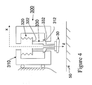
- Figure 4 shows an alternative embodiment of a placement device 300 according to the invention.
- parts of the displacement device 300 corresponding to those of the placement device 200 in Figure 3A-C have a reference number that is 100 higher.
- the other reference numbers are identical to those in Figure 3A-3C .
- the embodiment shown in Figure 4 differs from the embodiment of Figures 3A-3C in that the constrainment surfaces 312, 332 taper outward in a direction towards the resilient body 320.
- Figures 5A-5D show various alternative embodiments for the shape of the wall 224 of the bellows 220.
- parts corresponding to those in Figure 3A have a value that is 200 higher.
- the wall 424 of the bellow shaped body 420 therein has a rectangular shaped folds in a cross-section through the z-axis.
- parts corresponding to those in Figure 3A have a value that is 300 higher.
- the wall 524 of the bellow shaped body 520 therein has simple curved folds in a cross-section through the z-axis. Also more complex shapes are possible, as shown in Figure 5C and the detail thereof in Figure 5D .
- parts corresponding to those in Figure 3A have a value that is 400 higher.
- the bellows is arranged in line with the gripper.
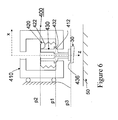
- the bellows may be enclosed by the gripper, as is illustrated in Figure 6 .
- parts corresponding to those in Figure 4 (other than the component 30 and the substrate 50) have a reference number that is 100 higher.
- the bellows 420 encloses the gripper 430.
- the bellows is mounted to the holder 300 in a plane p1 through the z-axis between a plane p2 through the mounting section 422 and a plane p3 through an end portion 236 for gripping the component 30.
Landscapes
- Engineering & Computer Science (AREA)
- Manufacturing & Machinery (AREA)
- Microelectronics & Electronic Packaging (AREA)
- Container, Conveyance, Adherence, Positioning, Of Wafer (AREA)
- Automatic Assembly (AREA)
Abstract
The placement device (200) comprises a holder (210), a resilient body (220) coupled to the holder (210) and a gripper (230). The gripper (230) is coupled to a mounting section (222) of the resilient body (220) and extending in a direction of a z-axis. The mounting section (222) is movable in a arbitrary directions and capable of tilting away from the z-axis. The gripper (230) and the holder (210) respectively have a first (232) and a second (212) constrainment surface. The first constrainment surface (232) of the gripper (230) is arranged between the mounting section (222) of the resilient body (220) and the second constrainment surface (212) of the holder (210). In an unloaded state of the placement device (200) the resilient body (220) forces the first constrainment surface (232) of the gripper (230) against the second constrainment surface (212) of the holder (210).
Description
- Placement devices are used for assembling components, e.g. components in hybrid microsystems, or for placing components on a substrate, e.g. a printed circuit board. Additionally placement devices may be used for other pick & place activities, such as taking components from a component supply belt and placing them on a location for further processing. When placing a component, such as in surface mounted device (SMD) technology or in a micro structure technology (MST) application on a carrier, e.g. a printed circuit board or a wafer, the component will in practice not be aligned with the wafer when it approaches the latter. One point of the component initially contacts the carrier, and subsequently the component rotates round a rotating point defined by the placement device until it reaches its final position. As the rotation point defined by the gripper has a different position that the first contactpoint between the component and the carrier, the component is forced to shift with respect to the carrier to reach a position defined by the placement device. This results in a positioning inaccuracy.
-
WO9308113 - It is a purpose of the present invention to provide an improved placement device.
- It is a further purpose of the present invention to provide an improved assembly device. It is a still further purpose of the present invention to provide an improved placement method.
- According to a first aspect of the invention a placement device as claimed in
claim 1 is provided. - According to a second aspect of the invention an assembly device as claimed in claim 6 is provided.
- According to a third aspect of the invention a placement method as claimed in
claim 7 is provided. - The placement device and placement method according to the invention initially, in an unloaded state, constrain the position and orientation of the component to be placed, but release the degrees of freedom X,Y, Z, Rx and Ry of the component when the component contacts the carrier. After the component contacts the carrier the placement device is loaded by the force that is exerted on it when an assembly device attempts to continue a movement of the placement device towards the carrier. Accordingly after its first contact with the carrier the component is allowed to move in arbitrary directions and to rotate around an arbitrary axis transverse to the z-axis, where the z-axis is the direction in which the component is placed. As these degrees of freedom are released upon the first contact of the component with the carrier, the component will rotate around the first point of contact until it is completely placed on the carrier. Hence, surprisingly, in the placement device according to the invention, releasing all but one degree of freedom during the placement, improves the placement accuracy of the component.
- In the placement device known from
WO9308113 - In the earlier filed, still unpublished European patent application
07110566.2 - The resilient body is for example a compressed volume of a resilient foam. The pressure exerted by the volume on the gripper causes the first constrainment surface of the gripper to rest against the second constrainment surface of the holder, so that the position and orientation of the gripper are fixed. Once the component to be placed has contacted the surface of the carrier a further progression of the holder to the surface causes the resilient body formed by the volume of foam to be further compressed, so that the first constrainment surface is released from the second constrainment surface. Now the position and orientation are no longer restrained by the constrainment surfaces. The mounting section is movable in a arbitrary directions and capable of tilting away from the z-axis. Accordingly the component is allowed to rotate around its first point of contact with the carrier, until it is completely and stably placed thereon.
- In a preferred embodiment the resilient body is a bellow-shaped hollow body. The bellow-shaped hollow body may be made of a resilient material like rubber, or it may be constructed of a more rigid material and have resilient behaviour due to its shape e.g. by a construction of circular extending corrugations like folds. Such a bellows shaped hollow body provides for the degrees of freedom X,Y,Z and Rx, Ry, but constrains the degree of freedom Rz. In this way it is prevented that the component can rotate in the plane of the carrier during its placement. As the bellows is hollow, its inside can serve as a vacuum tube for the gripper. Alternatively a vacuum may be provided via a separate tube, or different means may be used for allowing the gripper to hold a component. Depending on the required tension to be exerted on the gripper in the z-direction, and the required resistance against displacements in the x and y direction as well as the required resistance against a tilt from the z-direction, the skilled person can select a suitable material, a value for the thickness of the walls of the bellows, a diameter of the bellows, a height of the bellows and a number of folds in the walls. The stiffness of the resilient body in the directions x,y in preferably considerably lower than the stiffness in the z-direction. The stiffness in the z-direction may be increased by using an additional resilient element.
- In an embodiment the first and the second constrainment surface have a conical shape. The conical shapes of the constrainment surfaces allow the gripper to rapidly assume its reference position after the placement device is withdrawn. A conical shape having straight boundaries in a cross-section through the z-axis, but alternatively a shape having curved boundaries in said cross-section.
- In an embodiment the constrainment surfaces taper inward in a direction towards the resilient body. In an embodiment the constrainment surfaces taper outward in a direction towards the resilient body. This has the advantage that the placement device can have a compact construction.
- In an embodiment of the placement device the bellows partly encloses the gripper. This arrangement further facilitates a complex construction of the gripper.
- An assembly device according to the invention comprising a placement device according to any of the previous embodiments and further comprising a displacement device for relatively displacing the placement device in a direction transverse to the z-axis.
- These and other aspects of the invention are described in more detail with reference to the drawing.
Therein: -
Figure 1 schematically shows an assembly device, -
Figure 2 shows in cross-section a first embodiment of a placement device according to the invention in an unloaded state, -
Figure 3A shows in cross-section a second embodiment of a placement device according to the invention in an unloaded state, -
Figure 3B shows in cross-section the second embodiment of the placement device according to the invention in an intermediate state, -
Figure 3C shows in cross-section the second embodiment of the placement device according to the invention in an compressed state, -
Figure 4 shows in cross-section a third embodiment of a placement device according to the invention in an unloaded state, -
Figure 5A shows a detail of a cross-section of a part of the placement device ofFigures 3A-3C and4 , -
Figure 5B a shows this part in an enlarged representation, -
Figure 5C shows a variation of the part ofFigure 5A, 5B , -
Figure 5D shows a further variation of the part ofFigure 5A, 5B , -
Figure 6 shows in cross-section a fourth embodiment of a placement device according to the invention in an unloaded state. - In the following detailed description numerous specific details are set forth in order to provide a thorough understanding of the present invention. However, it will be understood by one skilled in the art that the present invention may be practiced without these specific details. In other instances, well known methods, procedures, and components have not been described in detail so as not to obscure aspects of the present invention.
- Embodiments of the invention are described herein with reference to cross-section illustrations that are schematic illustrations of idealized embodiments (and intermediate structures) of the invention. As such, variations from the shapes of the illustrations as a result, for example, of manufacturing techniques and/or tolerances, are to be expected. Thus, embodiments of the invention should not be construed as limited to the particular shapes of regions illustrated herein but are to include deviations in shapes that result, for example, from manufacturing.
- It will be understood that, although the terms first, second, third etc. may be used herein to describe various elements, components, regions, layers and/or sections, these elements, components, regions, layers and/or sections should not be limited by these terms. These terms are only used to distinguish one element, component, region, layer or section from another region, layer or section. Thus, a first element, component, region, layer or section discussed below could be termed a second element, component, region, layer or section without departing from the teachings of the present invention.
Figure 1 schematically shows anassembly device 1. Theassembly device 1 comprises aplacement device 100 and a displacement device for relatively displacing theplacement device 100 in a direction along a first axis (z) as well as a direction transverse to the first axis (x). The displacement device comprises afirst sledge 21 that is moveable along the x-axis along arail 22, and asecond sledge 23 that is movable with relatively to thefirst sledge 21 in the z-direction. Theplacement device 100 is arranged to grip acomponent 30 from aconveyor belt 40 for example and after being displaced by thedisplacement device circuit board 50. Although in the embodiment shown thefirst sledge 21 moves the placement device in a direction orthogonal to the z-direction the movement direction of the sledge may be in a direction orientated at another non-zero angle with the z-axis. Alternatively the displacement device may be capable of displacing the placement device in a range of directions. -
Figure 2 shows a first embodiment of aplacement device 100 according to the invention. Theplacement device 100 is shown in a cross-section. Theplacement device 100 is substantially circular rotation symmetric around the z-axis. Theplacement device 100 comprises aholder 110, aresilient body 120 coupled to theholder 110 and agripper 130. In the embodiment shown theresilient body 120 is a volume of elastic foam. Thegripper 130 is coupled to a mountingsection 122 of theresilient body 120 and extends in a direction of an z-axis. The mountingsection 122 is movable in a arbitrary directions x (horizontal), y (orthogonal to the plane of the drawing, not shown) and is capable of tilting away from the z-axis in a direction Rx (in the plane of the drawing) and Ry (orthogonal to the plane of the drawing, not shown). - The
gripper 130 and theholder 110 respectively have a first and asecond constrainment surface first constrainment surface 132 of thegripper 130 is arranged between the mountingsection 122 of theresilient body 120 and thesecond constrainment 112 surface of theholder 110.Figure 2 shows an unloaded state of theplacement device 100. Therein theresilient body 120 forces thefirst constrainment surface 132 of thegripper 130 against thesecond constrainment surface 112 of theholder 110. In the embodiment shown the first and the second constrainment surfaces 132, 112 have a conical shape. In particular the constrainment surfaces 132, 112 taper inward in a direction towards theresilient body 120. - In a practical implementation the gripper is a vacuum gripper, which is the most commonly used type of gripper applied in micro-assembly. However other embodiments are applicable, e.g. using electromagnetic force.
- As shown in
Figure 2 , a bottom surface of thecomponent 30 differs an angle α in alignment with a carrier, here a printedcircuit board 50.
Figure 3A shows a second embodiment of a placement device according to the invention. InFigure 3A parts of thedisplacement device 200 corresponding to those of theplacement device 100 inFigure 2 have a reference number that is 100 higher. The other reference numbers are identical to those inFigure 2 . In the embodiment shown inFigure 3A , theresilient body 220 is a bellow-shaped hollow body of a resilient material. In this embodiment the resilient body is of a stainless steel.Thehollow body 220 forms a vacuum tube for thegripper 130. As shown schematically inFigure 3A , thewall 224 of the bellow shaped body has a triangular shaped folds in a cross-section through the z-axis. Nevertheless other shapes are possible as is illustrated inFigures 5A-5D .Figure 3A , as well asFigure 2 , show a state where thecomponent 30 held by theplacement device carrier 30. Hence, the placement device is unloaded. -
Figure 3B shows a transition state wherein theplacement device 200 has moved towards the carrier until thecomponent 30 carried by theplacement device 200 touches thecarrier 50 at a first contact point CP. The contact point CP determines a position of the component by friction between the surfaces of thecomponent 30 and thecarrier 50 contacting each other in the contact point CP. The movement of the placement device now progresses until the end state as shown inFigure 3C . - Due to the continuing movement of the
displacement device 200 towards the surface of thecarrier 50 and due to the fact that thecomponent 30 is already constrained by the contact point P, the force exerted by theresilient body 220 is conquered. Consequently, theconstrainment surface 232 of thegripper 230 is at least partially released from theconstrainment surface 212 of theholder 210. Theendportion 234 of thegripper 230 can now freely move in arbitrary directions and tilt away from the z-axis. As the gripper is allowed these degrees of freedom, the component is allowed to rotate around the contact point CP. Therewith the point of thecomponent 30 that first contacted thecarrier 50 is not forced to shift over the surface of thecarrier 50. Moreover, in this preferred embodiment a rotation around the z-axis is blocked by theresilient body 220, so that thecomponent 30 is even more accurately placed on thecarrier 50. -
Figure 4 shows an alternative embodiment of aplacement device 300 according to the invention. InFigure 4 parts of thedisplacement device 300 corresponding to those of theplacement device 200 inFigure 3A-C have a reference number that is 100 higher. The other reference numbers are identical to those inFigure 3A-3C . The embodiment shown inFigure 4 differs from the embodiment ofFigures 3A-3C in that the constrainment surfaces 312, 332 taper outward in a direction towards theresilient body 320. -
Figures 5A-5D show various alternative embodiments for the shape of thewall 224 of thebellows 220. InFigure 5A , parts corresponding to those inFigure 3A have a value that is 200 higher. The wall 424 of the bellow shapedbody 420 therein has a rectangular shaped folds in a cross-section through the z-axis. InFigure 5B , parts corresponding to those inFigure 3A have a value that is 300 higher. Thewall 524 of the bellow shapedbody 520 therein has simple curved folds in a cross-section through the z-axis. Also more complex shapes are possible, as shown inFigure 5C and the detail thereof inFigure 5D . Therein parts corresponding to those inFigure 3A have a value that is 400 higher. - It is not necessary that the bellows is arranged in line with the gripper. Alternatively the bellows may be enclosed by the gripper, as is illustrated in
Figure 6 . InFigure 6 , parts corresponding to those inFigure 4 (other than thecomponent 30 and the substrate 50) have a reference number that is 100 higher. InFigure 6 thebellows 420 encloses thegripper 430. The bellows is mounted to theholder 300 in a plane p1 through the z-axis between a plane p2 through the mountingsection 422 and a plane p3 through an end portion 236 for gripping thecomponent 30. - Unless otherwise defined, all terms (including technical and scientific terms) used herein have the same meaning as commonly understood by one of ordinary skill in the art to which this invention belongs. It will be further understood that terms, such as those defined in commonly used dictionaries, should be interpreted as having a meaning that is consistent with their meaning in the context of the relevant art and will not be interpreted in an idealized or overly formal sense unless expressly so defined herein.
- In the claims the word "comprising" does not exclude other elements or steps, and the indefinite article "a" or "an" does not exclude a plurality. A single component or other unit may fulfill the functions of several items recited in the claims. The mere fact that certain measures are recited in mutually different claims does not indicate that a combination of these measures cannot be used to advantage. Any reference signs in the claims should not be construed as limiting the scope.
Claims (8)
- Placement device (200) comprising- a holder (210),- a resilient body (220) coupled to the holder (210),- a gripper (230) coupled to a mounting section (222) of the resilient body (220) and extending in a direction of a z-axis, the mounting section (222) being movable in a arbitrary directions and being capable of tilting away from the z-axis,- wherein the gripper (230) and the holder (210) respectively have a first (232) and a second (212) constrainment surface, the first constrainment surface (232) of the gripper (230) being arranged between the mounting section (222) of the resilient body (220) and the second constrainment surface (212) of the holder (210), wherein, in an unloaded state of the placement device (200) the resilient body (220) forces the first constrainment surface (232) of the gripper (230) against the second constrainment surface (212) of the holder (210).
- Placement device according to claim 1, wherein the resilient body (220) is a bellow-shaped hollow body.
- Placement device according to claim 1, wherein the first (232) and the second constrainment surface (212) have a conical shape.
- Placement device according to claim 3, wherein the constrainment surfaces (232, 212) taper inward in a direction towards the resilient body (220).
- Placement device according to claim 3, wherein the constrainment surfaces (332, 312) taper outward in a direction towards the resilient body (320).
- Placement device according to claim 2, wherein the bellows (420) partly encloses the gripper (430).
- An assembly device comprising a placement device according to any of the previous claims and further comprising a displacement device (21, 22, 23) for relatively displacing the placement device (10) in a direction (x) transverse to the z-axis.
- Method of placing a component on a carrier, comprising the steps of- fetching a component,- moving the component towards the carrier, while restraining all degrees of freedom of the component,- upon a first contact between the component and the carrier, releasing the degrees of freedom X,Y,Z,Rx,Ry, while restraining the degree of freedom Rz, wherein Z is the position of the component in a direction transverse to a plane of the carrier, and X and Y are mutually transverse directions indicating a position within said plane, and Rx, and Ry define a degree of freedom of rotating around said X-axis and said Y-axis, and Rz indicates the restrained freedom of rotating around the Z-axis.
Priority Applications (3)
| Application Number | Priority Date | Filing Date | Title |
|---|---|---|---|
| EP08151087A EP2088844A1 (en) | 2008-02-05 | 2008-02-05 | Placement device, assembly device and method of placing a component |
| EP09709296A EP2241169A2 (en) | 2008-02-05 | 2009-02-05 | Placement device, assembly device and method of placing a component |
| PCT/NL2009/050050 WO2009099327A2 (en) | 2008-02-05 | 2009-02-05 | Placement device, assembly device and method of placing a component |
Applications Claiming Priority (1)
| Application Number | Priority Date | Filing Date | Title |
|---|---|---|---|
| EP08151087A EP2088844A1 (en) | 2008-02-05 | 2008-02-05 | Placement device, assembly device and method of placing a component |
Publications (1)
| Publication Number | Publication Date |
|---|---|
| EP2088844A1 true EP2088844A1 (en) | 2009-08-12 |
Family
ID=39522183
Family Applications (2)
| Application Number | Title | Priority Date | Filing Date |
|---|---|---|---|
| EP08151087A Ceased EP2088844A1 (en) | 2008-02-05 | 2008-02-05 | Placement device, assembly device and method of placing a component |
| EP09709296A Withdrawn EP2241169A2 (en) | 2008-02-05 | 2009-02-05 | Placement device, assembly device and method of placing a component |
Family Applications After (1)
| Application Number | Title | Priority Date | Filing Date |
|---|---|---|---|
| EP09709296A Withdrawn EP2241169A2 (en) | 2008-02-05 | 2009-02-05 | Placement device, assembly device and method of placing a component |
Country Status (2)
| Country | Link |
|---|---|
| EP (2) | EP2088844A1 (en) |
| WO (1) | WO2009099327A2 (en) |
Cited By (2)
| Publication number | Priority date | Publication date | Assignee | Title |
|---|---|---|---|---|
| DE102011076857A1 (en) * | 2011-06-01 | 2012-12-06 | Robert Bosch Gmbh | Transfer device for transferring e.g. semiconductor chip on printed circuit board, has suction element resting at guide surface at region of guide element, where guide surface and cone-shaped guide surface form point- or circular contact |
| US9364953B2 (en) | 2012-07-24 | 2016-06-14 | Besi Switzerland Ag | Kinematic holding system for a placement head of a placement apparatus |
Citations (4)
| Publication number | Priority date | Publication date | Assignee | Title |
|---|---|---|---|---|
| US5029383A (en) * | 1990-06-07 | 1991-07-09 | Universal Instruments Corporation | Articulating tip for pick and place head |
| WO1993008113A1 (en) | 1991-10-24 | 1993-04-29 | Rich Donald S | Self-realigning vacuum pickup arrangement |
| EP0694798A2 (en) * | 1994-07-27 | 1996-01-31 | Eastman Kodak Company | Apparatus and method for automatic assembly of precision components |
| WO2006089742A2 (en) * | 2005-02-24 | 2006-08-31 | Aerolas Gmbh Aerostatische Lager Lasertechnik | Drive unit for a displaceable functional element |
-
2008
- 2008-02-05 EP EP08151087A patent/EP2088844A1/en not_active Ceased
-
2009
- 2009-02-05 EP EP09709296A patent/EP2241169A2/en not_active Withdrawn
- 2009-02-05 WO PCT/NL2009/050050 patent/WO2009099327A2/en not_active Ceased
Patent Citations (4)
| Publication number | Priority date | Publication date | Assignee | Title |
|---|---|---|---|---|
| US5029383A (en) * | 1990-06-07 | 1991-07-09 | Universal Instruments Corporation | Articulating tip for pick and place head |
| WO1993008113A1 (en) | 1991-10-24 | 1993-04-29 | Rich Donald S | Self-realigning vacuum pickup arrangement |
| EP0694798A2 (en) * | 1994-07-27 | 1996-01-31 | Eastman Kodak Company | Apparatus and method for automatic assembly of precision components |
| WO2006089742A2 (en) * | 2005-02-24 | 2006-08-31 | Aerolas Gmbh Aerostatische Lager Lasertechnik | Drive unit for a displaceable functional element |
Cited By (4)
| Publication number | Priority date | Publication date | Assignee | Title |
|---|---|---|---|---|
| DE102011076857A1 (en) * | 2011-06-01 | 2012-12-06 | Robert Bosch Gmbh | Transfer device for transferring e.g. semiconductor chip on printed circuit board, has suction element resting at guide surface at region of guide element, where guide surface and cone-shaped guide surface form point- or circular contact |
| DE102011076857B4 (en) * | 2011-06-01 | 2025-12-24 | Robert Bosch Gmbh | Transfer device for components |
| US9364953B2 (en) | 2012-07-24 | 2016-06-14 | Besi Switzerland Ag | Kinematic holding system for a placement head of a placement apparatus |
| US9956692B2 (en) | 2012-07-24 | 2018-05-01 | Besi Switzerland Ag | Kinematic holding system for a placement head of a placement apparatus |
Also Published As
| Publication number | Publication date |
|---|---|
| EP2241169A2 (en) | 2010-10-20 |
| WO2009099327A2 (en) | 2009-08-13 |
| WO2009099327A3 (en) | 2009-10-01 |
Similar Documents
| Publication | Publication Date | Title |
|---|---|---|
| Tsui et al. | Micromachined end-effector and techniques for directed MEMS assembly | |
| US10046924B2 (en) | Core conveying device and core conveying method | |
| EP2604398A2 (en) | Robot and robot hand | |
| US8834146B2 (en) | System for passive alignment of surfaces | |
| CN107000215B (en) | Flexible clamping device for a component stacking system, component stacking system and positioning method for positioning a clamping element of a component stacking system | |
| JP5606517B2 (en) | Vacuum gripper assembly stabilized by a spring | |
| JP2013086185A (en) | Holding device and robot | |
| KR20030093902A (en) | Handling apparatus and test set using the handling apparatus | |
| EP1313662A2 (en) | Edge gripping end effector wafer handling apparatus | |
| WO2009099327A2 (en) | Placement device, assembly device and method of placing a component | |
| JP6741414B2 (en) | Component mounting robot system | |
| CN102441790A (en) | Component assembling device and component assembling method | |
| JP2003344482A (en) | Probe card carrier and adapter | |
| JP2020049582A (en) | End effector device | |
| US10189132B2 (en) | Core grasping apparatus | |
| JP2002018759A (en) | Device and method for transferring ceramics columnar body | |
| KR20160076555A (en) | Mounting method of spring for touch switch | |
| Fontana et al. | Precision handling of electronic components for PCB rework | |
| Ruggeri et al. | Design strategies for vacuum micro-grippers with integrated release system | |
| KR102436663B1 (en) | Apparatus for loading component | |
| EP2007187A1 (en) | Placement device and assembly device | |
| JP5892783B2 (en) | Substrate support device and substrate transfer device | |
| KR20170068735A (en) | The Apparatus For Selecting Best Adaptable Nozzle And Speed | |
| US20030201652A1 (en) | Vacuum nozzle | |
| US10808868B2 (en) | Apparatus to assemble cable mounts |
Legal Events
| Date | Code | Title | Description |
|---|---|---|---|
| PUAI | Public reference made under article 153(3) epc to a published international application that has entered the european phase |
Free format text: ORIGINAL CODE: 0009012 |
|
| AK | Designated contracting states |
Kind code of ref document: A1 Designated state(s): AT BE BG CH CY CZ DE DK EE ES FI FR GB GR HR HU IE IS IT LI LT LU LV MC MT NL NO PL PT RO SE SI SK TR |
|
| AX | Request for extension of the european patent |
Extension state: AL BA MK RS |
|
| STAA | Information on the status of an ep patent application or granted ep patent |
Free format text: STATUS: THE APPLICATION HAS BEEN REFUSED |
|
| 18R | Application refused |
Effective date: 20090918 |