EP2088829A2 - Wireless transmitter device and method thereof for keeping the total transmission time limited - Google Patents
Wireless transmitter device and method thereof for keeping the total transmission time limited Download PDFInfo
- Publication number
- EP2088829A2 EP2088829A2 EP09152118A EP09152118A EP2088829A2 EP 2088829 A2 EP2088829 A2 EP 2088829A2 EP 09152118 A EP09152118 A EP 09152118A EP 09152118 A EP09152118 A EP 09152118A EP 2088829 A2 EP2088829 A2 EP 2088829A2
- Authority
- EP
- European Patent Office
- Prior art keywords
- time
- timer means
- value
- wireless transmitter
- data
- Prior art date
- Legal status (The legal status is an assumption and is not a legal conclusion. Google has not performed a legal analysis and makes no representation as to the accuracy of the status listed.)
- Withdrawn
Links
- 230000005540 biological transmission Effects 0.000 title claims abstract description 161
- 238000000034 method Methods 0.000 title claims description 14
- 238000009825 accumulation Methods 0.000 claims abstract description 35
- 230000002401 inhibitory effect Effects 0.000 claims description 7
- 238000004891 communication Methods 0.000 description 13
- 238000010586 diagram Methods 0.000 description 4
- 238000005259 measurement Methods 0.000 description 4
- 230000007704 transition Effects 0.000 description 4
- 230000006870 function Effects 0.000 description 3
- 230000008054 signal transmission Effects 0.000 description 3
- 238000004364 calculation method Methods 0.000 description 1
- 230000008859 change Effects 0.000 description 1
- 238000004590 computer program Methods 0.000 description 1
- 230000001276 controlling effect Effects 0.000 description 1
- 230000001105 regulatory effect Effects 0.000 description 1
- 230000004044 response Effects 0.000 description 1
- 230000000717 retained effect Effects 0.000 description 1
Images

Classifications
-
- H—ELECTRICITY
- H04—ELECTRIC COMMUNICATION TECHNIQUE
- H04M—TELEPHONIC COMMUNICATION
- H04M1/00—Substation equipment, e.g. for use by subscribers
- H04M1/66—Substation equipment, e.g. for use by subscribers with means for preventing unauthorised or fraudulent calling
- H04M1/667—Preventing unauthorised calls from a telephone set
- H04M1/67—Preventing unauthorised calls from a telephone set by electronic means
-
- H—ELECTRICITY
- H04—ELECTRIC COMMUNICATION TECHNIQUE
- H04W—WIRELESS COMMUNICATION NETWORKS
- H04W24/00—Supervisory, monitoring or testing arrangements
-
- H—ELECTRICITY
- H04—ELECTRIC COMMUNICATION TECHNIQUE
- H04W—WIRELESS COMMUNICATION NETWORKS
- H04W88/00—Devices specially adapted for wireless communication networks, e.g. terminals, base stations or access point devices
- H04W88/02—Terminal devices
-
- Y—GENERAL TAGGING OF NEW TECHNOLOGICAL DEVELOPMENTS; GENERAL TAGGING OF CROSS-SECTIONAL TECHNOLOGIES SPANNING OVER SEVERAL SECTIONS OF THE IPC; TECHNICAL SUBJECTS COVERED BY FORMER USPC CROSS-REFERENCE ART COLLECTIONS [XRACs] AND DIGESTS
- Y02—TECHNOLOGIES OR APPLICATIONS FOR MITIGATION OR ADAPTATION AGAINST CLIMATE CHANGE
- Y02D—CLIMATE CHANGE MITIGATION TECHNOLOGIES IN INFORMATION AND COMMUNICATION TECHNOLOGIES [ICT], I.E. INFORMATION AND COMMUNICATION TECHNOLOGIES AIMING AT THE REDUCTION OF THEIR OWN ENERGY USE
- Y02D30/00—Reducing energy consumption in communication networks
- Y02D30/70—Reducing energy consumption in communication networks in wireless communication networks
Definitions
- the present invention relates to a wireless transmitter device, and more particularly to a wireless transmitter device applicable for example to a wireless communication system in which the accumulated time of data transmission per predetermined duration is limited.
- the present invention also related to a method of wireless transmission for use in such a wireless communication system.
- Some types of wireless communication, devices limit a period of time for their data transmission.
- the total transmission period of time is so regulated that the accumulated transmission period of time per hour, i.e. "total transmission time” must fall within the range of 360 seconds according to the rules for international transportation data transmission specified low-power radio station defined by the Telecom Engineering Center, " Technical Standards for Specific Facilities", retrieved on December 28, 2007, on the website, http://www.telec.or.jp/tech/05_equipment/t243_01.html .
- the first method is to specify a transmission pause time so that the transmission time per hour is to be 360 seconds or less. For example, after a one-second transmission is completed, transmission must be paused for nine seconds or more so that the transmission time per hour can be shorter than 360 seconds.
- the transmission time ratio almost exceeds the value of 0.1, further transmission is inhibited until the predetermined period of time elapses in order to avoid the transmission time ratio in excess of 0.1.
- the predetermined period of time is 60 seconds
- the total transmission time is close to exceeding six seconds during the period of 60 seconds, the transmission is inhibited until the period of 60 seconds elapses.
- the above-described first and second methods however have the following problems.
- the first method fails to send data continuously. For example, if a packet is lost, then retransmission of the packet can only start when the pause time elapses after the loss of the packet is detected, which causes a delay before the retransmission.
- the timer must always operate even when no data traffic exists. This increases the power consumption. Especially, when the method is applied to a sensor network in which the communication device is driven by a battery, the timer always causes a problem of power consumption.
- a wireless transmitter device is capable of setting an upper limit of accumulated data transmission time per predetermined duration as a predetermined maximum accumulation time.
- the wireless transmitter device comprises a first timer for keeping time until a timeout value, which starts when the wireless transmitter device sends a wireless signal during the first timer is idle and stops when the first timer reaches the timeout value, a second timer for measuring an accumulation time of the data transmission of the wireless transmitter device during a period from the first timer starting to the first timer stopping, and a controller for inhibiting the data transmission of the wireless transmitter device at the earliest until the first timer reaches the timeout value either if it is determined that the accumulation time or a value based on the accumulation time is substantially equal to or larger than a threshold value, or if it is determined that the sum of the accumulation time and a time required to send other data or a value based on the sum is substantially equal to or larger than a threshold value.
- a wireless transmission program is executable on a computer installed in a wireless transmitter device having an upper limit of an accumulation time for data transmission within a predetermined duration.
- the program controls the computer to function as a first timer for keeping time until a timeout value, which starts when the wireless transmitter device sends a wireless signal during the first timer is idle and stops when the first timer reaches the timeout value, a second timer for measuring an accumulation time of the data transmission of the wireless transmitter device during a period from the first timer starting to the first timer stopping, and a controller for inhibiting the data transmission of the wireless transmitter device at the earliest until the first timer reaches the timeout value either if it is determined that the accumulation time or a value based on the accumulation time is substantially equal to or larger than a threshold value, or if it is determined that the sum of the accumulation time and a time required to send other data or a value based on the sum is substantially equal to or larger than a threshold value.
- a method of wireless transmission according to the present invention in a wireless transmitter device which has an upper limit of an accumulation time for data transmission within a predetermined duration, and comprises a first timer, a second timer and a controller, includes the steps of keeping time until a timeout value by the first timer which starts when the wireless transmitter device sends a wireless signal during the first timer is idle and stops when the first timer reaches the timeout value, measuring an accumulation time of the data transmission of the wireless transmitter device by the second timer during a period from the first timer starting to the first timer stopping, and inhibiting the data transmission of the wireless transmitter device by the controller at the earliest until the first timer reaches the timeout value either if it is determined that the accumulation time or a value based on the accumulation time is substantially equal to or larger than a threshold value, or if it is determined that the sum of the accumulation time and a time required to send other data or a value based on the sum is substantially equal to or larger than a threshold value.
- a wireless transmitter device for which the upper limit of the total transmission time per predetermined duration is specified can continuously send a wireless signal without delay, thus reducing power consumption.
- FIG. 1 is a schematic block diagram illustrating a specific overall structure of the wireless communication system 1.
- the wireless communication system 1 comprises a wireless transmitter device 10 and a wireless receiver 12.
- the wireless transmitter device 10 sends data 14 wirelessly, e.g. on radiowave, and the wireless receiver 12 receives it.
- the wireless transmitter device 10 is controlled in such a way that the total transmission time of data sent per predetermined time, or "T_interval", is shorter than a predetermined maximum total transmission time, or "T_maxsend".
- T_interval the total transmission time of data sent per predetermined time
- T_maxsend a predetermined maximum total transmission time
- the wireless transmitter device 10 is controlled to conform to the above-stated rules, and therefore the T_interval is set to one hour (3600 seconds) and the T_maxsend to 360 seconds.
- the T_interval and T_maxsend may be set to any appropriate value.
- the wireless communication system 1 consists of one wireless transmitter device 10 and one wireless receiver 12. However the communication system 1 may include multiple transmitter devices and receivers.
- the wireless transmitter device 10 comprises, as shown in FIG. 1 , a wireless transmitter 16, a total transmission time measurer 18, a timer 20 and a transmission controller 22.
- the wireless transmitter device 10 may include the configuration for executing computer programs, which comprises a CPU (Central Processing Unit), a ROM (Read Only Memory) , a RAM (Random Access Memory) , an EEPROM (Electrically Erasable and Programmable Read Only Memory), and a hard disk, and an interface for wireless communication.
- the wireless transmitter device 10 can attain the above functions by installing and executing a wireless transmission program or the like. Needless to say, the wireless transmitter device 10 may not be implemented by a single unit but by several units attaining the functions by the distributed processing.
- the wireless transmitter 16 is adapted for transmitting data 14 to other wireless communication devices, i.e. the wireless receiver 12 in the case of the illustrative embodiment, under the control of the transmission controller 22. Before transmitting the data 14 to the wireless receiver 12, the wireless transmitter 16 sends a send request signal 24 to the transmission controller 22 . Then, if the wireless transmitter 16 receives in turn a send-available signal 26 from the transmission controller 22, then it transmits the data 14 to the wireless receiver 12. If the transmitter 16 receives a send-unavailable signal 26, it cancels the data transmission. In the description, signals are thus designated with reference numerals of connections on which they are conveyed.
- the total transmission time (TTT) measurer 18 is adapted for measuring the accumulation period of time in which data are transmitted from the wireless transmitter 16 to other wireless communication devices.
- the TTT measurer 18 measures cumulatively the period or time. based on information 27 from the wireless transmitter 16 on an actual transmission time consumed in sending each piece of data.
- the TTT measurer 18 starts and stops measuring the accumulation time and resets the measured time value 28 under the control of the transmission controller 22.
- the timer 20 is adapted to start and stop itself, i.e. time keeping or measurement, and resets the measured time value 30 under the control of the transmission controller 22.
- the measured time value 30 reaches a timeout value derived by dividing the time value 28 by a predetermined transmission time ratio, i.e. "R_send"
- the timer 20 notifies the transmission controller 22 of its timeout.
- the R send will be detailed later.
- the transmission controller 22 is adapted for controlling those structural sections of the wireless transmitter device 10.
- the transmission controller 22 sends control signals 32 and 34 to the TTT measurer 18 and the timer 20, respectively, to control them, and receives information on the measured time values 28 and 30.
- the transmission controller 22 determines whether or not the requested data should be sent based on the measured time values 28 and 30 of the TTT measurer 18 and the timer 20, respectively, and returns the determining result 26 to the wireless transmitter 16.
- the transmission controller 22 when the transmission controller 22 receives the data send request signal 24 from the wireless transmitter 16, it permits the wireless transmitter 16 to send the requested data, and thereafter determines whether or not other data can be send by the wireless transmitter 16 following the required and transmitted data.
- the transmission controller 22 makes a determination in such a manner that (i) the sum of a currently measured time of the TTT measurer 18 and a time required to transmit data with its length corresponding to the maximum transmittable length is divided by a transmission time ratio, R_send, and then (ii) when the obtained value is smaller than the predetermined maximum value of the timer 20, "T_maxtimeout", the transmission controller 22 determines it "transmittable", and otherwise, i.e. if larger, then "not transmittable".
- the transmission controller 22 After the transmission controller 22 determines the next data cannot be sent, it returns a send-unavailable signal 26 to the transmitter 16, at the earliest, until the measured time or the timer 20 reaches the timeout value to inhibit data transmission from the transmitter device 10 to the receiver 12, even when the wireless transmitter 16 issues a data send request.
- the transmission time ratio is substantially equal to or smaller than the R_send.
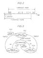
- FIG. 2 is a time chart illustrating an example of timing for wireless signal transmission for use in understanding that the total transmission time per T_interval may vary depending on the T_intervals when the transmission timing deviates.
- the upper limit of the total transmission time during the total transmission time measuring period i.e. "T_observe” [second]
- T_observe could be set to 360 x (T_observe/3600) [second] so that the ratio per T_observe is substantially equal to the transmission time ratio per hour, i.e. per T_interval.
- the transmission timing deviates as shown in FIG. 2 for example, the total transmission time per hour would exceed 360 seconds depending on the T_intervals.
- the total transmission time per hour would be shorter than 360 seconds in the case the transmission timing involves no deviation. However, if the transmission timing deviates as shown in FIG. 2 , the total transmission time per hour would be 366 seconds at the maximum depending on the timing of the T_interval.
- the upper limit of the total transmission time during the T_observe is defined by the following Expression (1), for example.
- the upper limit of the total transmission time during the period of T_observe ⁇ T_maxsend / T_interval / T_observe with fraction rounded - up + 1
- the upper limit of the total transmission time during the T_observe i.e. 60 seconds, obtained from the Expression (1) is equal to 5.9 seconds as seen from the Expression (2) below.
- the upper limit of the total transmission time during the T_observe may be set to satisfy the Expression (1) above to thereby ensure the total transmission time not to exceed the T_maxsend during any of the T intervals.
- the R-send may be expressed by the following Expression (4), which can be obtained from the Expression (1) using the maximum timeout value T_maxtimeout, since the timeout value is assumed to be the T_observe in the Expression (1).
- FIG. 3 is a state transition diagram useful for understanding the state transition the wireless transmitter device 10 during its transmission process.
- initialisation S100 follows. Then, the timer 20 and the TTT measurer 18 enter their idle or standby states S101 where they are idle (timer OFF) and the transmission controller 22 enters its data transmission available state where it is ready to receive a send request signal and return a send-available signal (send-available).
- the TTT measurer 18 resets the value retained therein and starts measuring the transmission time. Also the timer 20 resets itself and starts time keeping. Then, the data send-available signal 26 is returned from the transmission controller 22 to the wireless transmitter 16, and the wireless transmitter 16 starts sending the requested data 14. Then, the transmission controller 22 determines whether or not it is possible to send other data after the wireless transmitter 16 completes this data transmission (S102).
- send-available i.e. transmittable (OK)
- the timer 20 continue time measuring, i.e. timer ON, and the transmission controller 22 keeps the data transmission available state S103 (send-available).
- the wireless transmitter 16 notifies the transmission controller 22 of another data send request, the transmission controller 22 sends a send-available signal 26 and makes determination of the next data transmission availability (S102).
- send-unavailable i.e. not-transmittable (NG)
- the transmission controller 22 enters its intransmittable state S104 (send-unavailable) so as not to send data, whereas the time-measuring by the timer 20 continues (i.e. timer ON).
- send-unavailable state S104 even when a send request is issued from the wireless transmitter 16 to the transmission controller 22, a send-unavailable signal 26 is returned.
- the wireless transmitter device 10 can control its transmission so that the total transmission time per T_interval does not exceed the maximum total transmission time, T_maxsend, by means of the transmission controller 22, the TTT measurer 18 and the timer 20,
- the wireless transmitter device 10 can send data without involving any delay during a period from the timer 20 starts time measuring until the measured time reaches the T maxtimeout as far as the transmission time ratio is substantially equal to or less than R_send.
- the TTT measurer 18 and the timer 20 start time measurement using a send request from the wireless transmitter 16 as a trigger and once stop after the measured time of the timer 20 reaches the timeout, value. Then, they restart their time measurement when another send request is received. Thus, the TTT measurer 18 and the timer 20 will not operate while the wireless transmitter device 10 sends no data, thereby reducing the power consumption in the wireless transmitter device 10.
- the transmission controller 22 can control the data transmission in such a way that the time derived by dividing a time measured with the TTT measurer 18 by the R_send is substantially shorter than the T_maxtimeout, and that the R_send is set to satisfy the above-described Expression (4) , the total transmission time per T_interval will not exceed the maximum total transmission time, T_maxsend, even when data transmission timing deviates as shown in and described with reference to FIG. 2 , for example.
- the TTT measurer 18 of the illustrative embodiment described above measures the time during which the wireless transmitter 16 actually performs transmission.
- the total transmission time may be derived by calculating the time required to transmit data to be sent from the wireless transmitter 16 based on the size of the data and accumulating the calculation results.
- the transmission controller 22 is responsive to a send request issued from the wireless transmitter 16 to start, transmitting the data, and subsequently determine whether or not the next data are transmittable. Instead, every time the transmission controller 22 receives a data send request from the wireless transmitter 16, it may determine the send availability until it determines not transmittable.
- the transmission controller 22 may determine the send availability in such a way that it determines not transmittable either (i) only when the total transmission time including the transmission time when the next data requested by the wireless transmitter 16 have been transmitted is calculated and it is determined that a value resultant from dividing the total transmission time by the R_send exceeds the T_maxtimeout, or (ii) only when a value derived by dividing the time measured with the TTT measurer 18 by a predetermined transmission time ratio is larger than the T_maxtimeout.
- the transmission controller 22 applies uniformly to all data the same threshold value, i.e. the maximum timeout value T_maxtimeout, for determining the data send availability in the above-described state S102 shown in FIG. 3 .
- the send availability may be determined by applying different threshold values depending on the priority of data. For example, a lower threshold value may be set for lower priority data, while a higher threshold value may be set for higher priority data. In this way, for example, even when a large amount of low priority data is generated, data with higher priority can preferentially be sent.
- the priority of each pieces of data may be determined according to the header information of the data.
- each pieces of data may have information on the acceptable delay amount in sending data.
- the transmission controller 22 may refrain from forwarding a response to the send request of the data and wait for the transition to the state S101 after timed out to thence return a send-available signal for the data to the wireless transmitter 16.
- the acceptability of delay amount of data may be determined from information carried on the header of the data.
- the transmission controller 22 controls the data transmission in such way that a value derived by dividing the total transmission time by the R_send will not exceed the T_maxtimeout.
- an alternative control way may be applicable in which the total transmission time per se will not exceed a predetermined threshold value.
- This threshold value may be set so as to satisfy the Expression (5) indicated below, which is resultant from replacing the T_observe in the Expression (1) with the T_maxtimeout.
- the transmission controller 22 sets the R_send to a value according to the above-described Expression (4). Instead, it may set so that R_send ⁇ T_maxsend/T_interval. For example, if the T_interval is set to 3600 seconds and the T_maxsend is set to 360 seconds, then the R_send may be set to the value of 0.1 or less.
- a wireless transmitter device (10) has a predetermined upper limit of an accumulated data transmission time per predetermined duration corresponding to a predetermined maximum value.
- the wireless transmitter device (10) includes a timer (20) which starts keeping time when the wireless transmitter device (10) sends a wireless signal and stops when it reaches a timeout value, a total transmission time measurer (18) for measuring the data transmission time of the wireless transmitter device (10) during a period from the timer (20) starting to stopping, and a transmission controller (22) for refraining the data transmission at the earliest until the time being measured by the timer (20) reaches the timeout value if the accumulation time is, or likely to be, equal to or larger than a threshold value.
Landscapes
- Engineering & Computer Science (AREA)
- Computer Security & Cryptography (AREA)
- Signal Processing (AREA)
- Mobile Radio Communication Systems (AREA)
- Transmitters (AREA)
Abstract
Description
- The present invention relates to a wireless transmitter device, and more particularly to a wireless transmitter device applicable for example to a wireless communication system in which the accumulated time of data transmission per predetermined duration is limited. The present invention also related to a method of wireless transmission for use in such a wireless communication system.
- Some types of wireless communication, devices limit a period of time for their data transmission. For example, with specified low-power radio stations for use in international transportation data transmission, the total transmission period of time is so regulated that the accumulated transmission period of time per hour, i.e. "total transmission time", must fall within the range of 360 seconds according to the rules for international transportation data transmission specified low-power radio station defined by the Telecom Engineering Center, "Technical Standards for Specific Facilities", retrieved on December 28, 2007, on the website, http://www.telec.or.jp/tech/05_equipment/t243_01.html.
- Methods that satisfy the above rule include those which follow. The first method is to specify a transmission pause time so that the transmission time per hour is to be 360 seconds or less. For example, after a one-second transmission is completed, transmission must be paused for nine seconds or more so that the transmission time per hour can be shorter than 360 seconds.
- In the second method, the total transmission time per predetermined period of time is measured, and the ratio of total transmission time, or "transmission time ratio", is controlled so as not to be larger than the value of (360 seconds) / (1 hour =3600 seconds) 0.1. When the transmission time ratio almost exceeds the value of 0.1, further transmission is inhibited until the predetermined period of time elapses in order to avoid the transmission time ratio in excess of 0.1. For example, in the case that the predetermined period of time is 60 seconds, the total transmission time is close to exceeding six seconds during the period of 60 seconds, the transmission is inhibited until the period of 60 seconds elapses.
- The above-described first and second methods however have the following problems. The first method fails to send data continuously. For example, if a packet is lost, then retransmission of the packet can only start when the pause time elapses after the loss of the packet is detected, which causes a delay before the retransmission.
- In the second method described above, the timer must always operate even when no data traffic exists. This increases the power consumption. Especially, when the method is applied to a sensor network in which the communication device is driven by a battery, the timer always causes a problem of power consumption.
- It is therefore an object of the present invention to provide a wireless transmitter device which has its total transmission time per predetermined duration specified to an upper limit and enables a signal transmission with minimized delay and reduced in power consumption even for continuously transmitting wireless signals. It is also an object of the invention to provide a method of wireless transmission for such a wireless transmitter device.
- A wireless transmitter device according to the present invention is capable of setting an upper limit of accumulated data transmission time per predetermined duration as a predetermined maximum accumulation time. The wireless transmitter device comprises a first timer for keeping time until a timeout value, which starts when the wireless transmitter device sends a wireless signal during the first timer is idle and stops when the first timer reaches the timeout value, a second timer for measuring an accumulation time of the data transmission of the wireless transmitter device during a period from the first timer starting to the first timer stopping, and a controller for inhibiting the data transmission of the wireless transmitter device at the earliest until the first timer reaches the timeout value either if it is determined that the accumulation time or a value based on the accumulation time is substantially equal to or larger than a threshold value, or if it is determined that the sum of the accumulation time and a time required to send other data or a value based on the sum is substantially equal to or larger than a threshold value.
- A wireless transmission program according to the present invention is executable on a computer installed in a wireless transmitter device having an upper limit of an accumulation time for data transmission within a predetermined duration. The program controls the computer to function as a first timer for keeping time until a timeout value, which starts when the wireless transmitter device sends a wireless signal during the first timer is idle and stops when the first timer reaches the timeout value, a second timer for measuring an accumulation time of the data transmission of the wireless transmitter device during a period from the first timer starting to the first timer stopping, and a controller for inhibiting the data transmission of the wireless transmitter device at the earliest until the first timer reaches the timeout value either if it is determined that the accumulation time or a value based on the accumulation time is substantially equal to or larger than a threshold value, or if it is determined that the sum of the accumulation time and a time required to send other data or a value based on the sum is substantially equal to or larger than a threshold value.
- A method of wireless transmission according to the present invention in a wireless transmitter device, which has an upper limit of an accumulation time for data transmission within a predetermined duration, and comprises a first timer, a second timer and a controller, includes the steps of keeping time until a timeout value by the first timer which starts when the wireless transmitter device sends a wireless signal during the first timer is idle and stops when the first timer reaches the timeout value, measuring an accumulation time of the data transmission of the wireless transmitter device by the second timer during a period from the first timer starting to the first timer stopping, and inhibiting the data transmission of the wireless transmitter device by the controller at the earliest until the first timer reaches the timeout value either if it is determined that the accumulation time or a value based on the accumulation time is substantially equal to or larger than a threshold value, or if it is determined that the sum of the accumulation time and a time required to send other data or a value based on the sum is substantially equal to or larger than a threshold value.
- According to the present invention, a wireless transmitter device for which the upper limit of the total transmission time per predetermined duration is specified can continuously send a wireless signal without delay, thus reducing power consumption.
- The objects and features of the present invention will become more apparent from consideration of the following detailed description taken in conjunction with the accompanying drawings in which:
-
FIG. 1 is a schematic block diagram illustrating the overall structure of a wireless communication system according to an illustrative embodiment of the present invention; -
FIG. 2 is a time chart illustrating an example of timing for wireless signal transmission useful for understanding the difference of the total transmission time in the same length periods; and -
FIG. 3 is a descriptive diagram useful for understanding the state transition of the wireless transmitter device according to the embodiment. - Now, a preferred embodiment of a wireless transmitter device according to the present invention will be described in detail with reference to the accompanying drawings. For the purpose of making the present invention understood clearer, the description will be concentrated on a simplified case where one wireless transmitter device tries to transmit data to a wireless receiver.
- Reference is first made to
FIG. 1 , which is a schematic block diagram illustrating a specific overall structure of thewireless communication system 1. As seen from the figure, thewireless communication system 1 comprises awireless transmitter device 10 and awireless receiver 12. - In the
wireless communication system 1, thewireless transmitter device 10 sendsdata 14 wirelessly, e.g. on radiowave, and thewireless receiver 12 receives it. Thewireless transmitter device 10 is controlled in such a way that the total transmission time of data sent per predetermined time, or "T_interval", is shorter than a predetermined maximum total transmission time, or "T_maxsend". In the present embodiment, thewireless transmitter device 10 is controlled to conform to the above-stated rules, and therefore the T_interval is set to one hour (3600 seconds) and the T_maxsend to 360 seconds. Of course, the T_interval and T_maxsend may be set to any appropriate value. In the system shown inFIG. 1 , thewireless communication system 1 consists of onewireless transmitter device 10 and onewireless receiver 12. However thecommunication system 1 may include multiple transmitter devices and receivers. - The
wireless transmitter device 10 according to the present embodiment comprises, as shown inFIG. 1 , awireless transmitter 16, a totaltransmission time measurer 18, atimer 20 and atransmission controller 22. Thewireless transmitter device 10 may include the configuration for executing computer programs, which comprises a CPU (Central Processing Unit), a ROM (Read Only Memory) , a RAM (Random Access Memory) , an EEPROM (Electrically Erasable and Programmable Read Only Memory), and a hard disk, and an interface for wireless communication. In this case, thewireless transmitter device 10 can attain the above functions by installing and executing a wireless transmission program or the like. Needless to say, thewireless transmitter device 10 may not be implemented by a single unit but by several units attaining the functions by the distributed processing. - The
wireless transmitter 16 is adapted for transmittingdata 14 to other wireless communication devices, i.e. thewireless receiver 12 in the case of the illustrative embodiment, under the control of thetransmission controller 22. Before transmitting thedata 14 to thewireless receiver 12, thewireless transmitter 16 sends asend request signal 24 to thetransmission controller 22 . Then, if thewireless transmitter 16 receives in turn a send-available signal 26 from thetransmission controller 22, then it transmits thedata 14 to thewireless receiver 12. If thetransmitter 16 receives a send-unavailable signal 26, it cancels the data transmission. In the description, signals are thus designated with reference numerals of connections on which they are conveyed. - The total transmission time (TTT)
measurer 18 is adapted for measuring the accumulation period of time in which data are transmitted from thewireless transmitter 16 to other wireless communication devices. In the present embodiment, the TTT measurer 18 measures cumulatively the period or time. based oninformation 27 from thewireless transmitter 16 on an actual transmission time consumed in sending each piece of data. The TTT measurer 18 starts and stops measuring the accumulation time and resets the measuredtime value 28 under the control of thetransmission controller 22. - The
timer 20 is adapted to start and stop itself, i.e. time keeping or measurement, and resets the measuredtime value 30 under the control of thetransmission controller 22. When the measuredtime value 30 reaches a timeout value derived by dividing thetime value 28 by a predetermined transmission time ratio, i.e. "R_send", thetimer 20 notifies thetransmission controller 22 of its timeout. The R send will be detailed later. - The
transmission controller 22 is adapted for controlling those structural sections of thewireless transmitter device 10. Thetransmission controller 22 sendscontrol signals TTT measurer 18 and thetimer 20, respectively, to control them, and receives information on the measuredtime values send request signal 24 from thewireless transmitter 16, thetransmission controller 22 determines whether or not the requested data should be sent based on the measuredtime values TTT measurer 18 and thetimer 20, respectively, and returns thedetermining result 26 to thewireless transmitter 16. - In the present embodiment, when the
transmission controller 22 receives the datasend request signal 24 from thewireless transmitter 16, it permits thewireless transmitter 16 to send the requested data, and thereafter determines whether or not other data can be send by thewireless transmitter 16 following the required and transmitted data. - In order to obtain a result from the determination which is available even when the next data has its length maximum for transmission by the wireless transmitter device, the
transmission controller 22 makes a determination in such a manner that (i) the sum of a currently measured time of theTTT measurer 18 and a time required to transmit data with its length corresponding to the maximum transmittable length is divided by a transmission time ratio, R_send, and then (ii) when the obtained value is smaller than the predetermined maximum value of thetimer 20, "T_maxtimeout", thetransmission controller 22 determines it "transmittable", and otherwise, i.e. if larger, then "not transmittable". - After the
transmission controller 22 determines the next data cannot be sent, it returns a send-unavailable signal 26 to thetransmitter 16, at the earliest, until the measured time or thetimer 20 reaches the timeout value to inhibit data transmission from thetransmitter device 10 to thereceiver 12, even when thewireless transmitter 16 issues a data send request. - In this way, in the period of time commencing from the
timer 20 starting time keeping or measurement until a measured time reaching the timeout value, it is ensured that the transmission time ratio is substantially equal to or smaller than the R_send. - Now, detailed will be the value set as the transmission time ratio, R_send, by the
transmission controller 22 with reference toFIG. 2 . -
FIG. 2 is a time chart illustrating an example of timing for wireless signal transmission for use in understanding that the total transmission time per T_interval may vary depending on the T_intervals when the transmission timing deviates. For example, the upper limit of the total transmission time during the total transmission time measuring period, i.e. "T_observe" [second], could be set to 360 x (T_observe/3600) [second] so that the ratio per T_observe is substantially equal to the transmission time ratio per hour, i.e. per T_interval. However, if the transmission timing deviates as shown inFIG. 2 , for example, the total transmission time per hour would exceed 360 seconds depending on the T_intervals. - More specifically, if the T_observe could be set to 60 seconds and the total transmission time during the T_observe to six (6) seconds or less, then the total transmission time per hour would be shorter than 360 seconds in the case the transmission timing involves no deviation. However, if the transmission timing deviates as shown in
FIG. 2 , the total transmission time per hour would be 366 seconds at the maximum depending on the timing of the T_interval. - In order to avoid this problem, in the present embodiment, the upper limit of the total transmission time during the T_observe is defined by the following Expression (1), for example.
The upper limit of the total transmission time during the period of T_observe
- For example, in the case of T_interval = 3600 seconds, T_maxsend = 360 seconds and T_observe = 60 seconds, the upper limit of the total transmission time during the T_observe, i.e. 60 seconds, obtained from the Expression (1) is equal to 5.9 seconds as seen from the Expression (2) below.
The upper limit of the total transmission time during the period
- Thus, if the transmission timing does not deviate, the total transmission time per T_interval, i.e. per hour, is equal to 354 seconds as seen from the Expression (3) below.

- Therefore, when adding to this result the upper limit of the total transmission time (5.9 seconds) during each T_observe as derived from the Expression (2) above, the result is 354 + 5.9 = 359.9 seconds. The latter tells that, even when the transmission timing deviates as shown in
FIG. 2 , it is ensured that the total transmission time during the T_interval (3600 seconds) never exceeds the T_maxsend (360 seconds). Therefore, regardless of whether or not the timing deviates, the total transmission time during the T_interval never exceeds the T_maxsend (360 seconds). - In the case that the
wireless transmitter 16 has to maintain its total transmission time per T_interval not exceeding the T_maxsend, the upper limit of the total transmission time during the T_observe may be set to satisfy the Expression (1) above to thereby ensure the total transmission time not to exceed the T_maxsend during any of the T intervals. - Thus, in order to ensure the maximum total transmission time, T_maxsend, per T_interval, the R-send may be expressed by the following Expression (4), which can be obtained from the Expression (1) using the maximum timeout value T_maxtimeout, since the timeout value is assumed to be the T_observe in the Expression (1).

Under the condition, any total transmission time does not exceed the T_maxsend. - With reference to
FIG. 3 , a description will be given of the operation of thewireless transmitter device 10 according to the embodiment.FIG. 3 is a state transition diagram useful for understanding the state transition thewireless transmitter device 10 during its transmission process. - When at first the
wireless transmitter device 10 is activated, initialisation S100 follows. Then, thetimer 20 and theTTT measurer 18 enter their idle or standby states S101 where they are idle (timer OFF) and thetransmission controller 22 enters its data transmission available state where it is ready to receive a send request signal and return a send-available signal (send-available). - In the above-described state S101, when the data send
request signal 24 is sent from thewireless transmitter 16 to thetransmission controller 22, theTTT measurer 18 resets the value retained therein and starts measuring the transmission time. Also thetimer 20 resets itself and starts time keeping. Then, the data send-available signal 26 is returned from thetransmission controller 22 to thewireless transmitter 16, and thewireless transmitter 16 starts sending the requesteddata 14. Then, thetransmission controller 22 determines whether or not it is possible to send other data after thewireless transmitter 16 completes this data transmission (S102). - In the above-described state S102, if determined send-available, i.e. transmittable (OK), then the
timer 20 continue time measuring, i.e. timer ON, and thetransmission controller 22 keeps the data transmission available state S103 (send-available). - In the above-described state S103, the
wireless transmitter 16 notifies thetransmission controller 22 of another data send request, thetransmission controller 22 sends a send-available signal 26 and makes determination of the next data transmission availability (S102). - In the above-described state S103, when the time measured by the
timer 20 reaches the timeout value, thetimer 20 notifies thetransmission controller 22 of the timeout, and theTTT measurer 18 and thetimer 20 enter their idle state (timer OFF), whereas thetransmission controller 22 keeps its send available state (S101). - In the above-described state S102, if determined send-unavailable, i.e. not-transmittable (NG) , then the
transmission controller 22 enters its intransmittable state S104 (send-unavailable) so as not to send data, whereas the time-measuring by thetimer 20 continues (i.e. timer ON). In the send-unavailable state S104, even when a send request is issued from thewireless transmitter 16 to thetransmission controller 22, a send-unavailable signal 26 is returned. - In the above-described state S104, when the time measured by the
timer 20 reaches the timeout value, thetimer 20 notifies thetransmission controller 22 of the timeout. Then, theTTT measurer 18 and thetimer 20 enter into their idle state S101 (timer OFF). - In the present illustrative embodiment, the
wireless transmitter device 10 can control its transmission so that the total transmission time per T_interval does not exceed the maximum total transmission time, T_maxsend, by means of thetransmission controller 22, theTTT measurer 18 and thetimer 20, - Further, the
wireless transmitter device 10 can send data without involving any delay during a period from thetimer 20 starts time measuring until the measured time reaches the T maxtimeout as far as the transmission time ratio is substantially equal to or less than R_send. - Further, the
TTT measurer 18 and thetimer 20 start time measurement using a send request from thewireless transmitter 16 as a trigger and once stop after the measured time of thetimer 20 reaches the timeout, value. Then, they restart their time measurement when another send request is received. Thus, theTTT measurer 18 and thetimer 20 will not operate while thewireless transmitter device 10 sends no data, thereby reducing the power consumption in thewireless transmitter device 10. - Further, since the
transmission controller 22 can control the data transmission in such a way that the time derived by dividing a time measured with theTTT measurer 18 by the R_send is substantially shorter than the T_maxtimeout, and that the R_send is set to satisfy the above-described Expression (4) , the total transmission time per T_interval will not exceed the maximum total transmission time, T_maxsend, even when data transmission timing deviates as shown in and described with reference toFIG. 2 , for example. - While the present invention has been described with reference to the particular illustrative embodiment, it is not to be restricted by the embodiment. It is to be appreciated that those skilled in the art can change or modify the embodiments without departing from the scope and spirit of the present invention.
- For example, for measuring the total transmission time, the
TTT measurer 18 of the illustrative embodiment described above measures the time during which thewireless transmitter 16 actually performs transmission. Instead, the total transmission time may be derived by calculating the time required to transmit data to be sent from thewireless transmitter 16 based on the size of the data and accumulating the calculation results. - Further, in the above-described embodiment, the
transmission controller 22 is responsive to a send request issued from thewireless transmitter 16 to start, transmitting the data, and subsequently determine whether or not the next data are transmittable. Instead, every time thetransmission controller 22 receives a data send request from thewireless transmitter 16, it may determine the send availability until it determines not transmittable. In the latter case, thetransmission controller 22 may determine the send availability in such a way that it determines not transmittable either (i) only when the total transmission time including the transmission time when the next data requested by thewireless transmitter 16 have been transmitted is calculated and it is determined that a value resultant from dividing the total transmission time by the R_send exceeds the T_maxtimeout, or (ii) only when a value derived by dividing the time measured with theTTT measurer 18 by a predetermined transmission time ratio is larger than the T_maxtimeout. - Further, in the above-described embodiment, the
transmission controller 22 applies uniformly to all data the same threshold value, i.e. the maximum timeout value T_maxtimeout, for determining the data send availability in the above-described state S102 shown inFIG. 3 . Alternatively, the send availability may be determined by applying different threshold values depending on the priority of data. For example, a lower threshold value may be set for lower priority data, while a higher threshold value may be set for higher priority data. In this way, for example, even when a large amount of low priority data is generated, data with higher priority can preferentially be sent. The priority of each pieces of data may be determined according to the header information of the data. - Furthermore, each pieces of data may have information on the acceptable delay amount in sending data. In this case, if, in the above-described state S102 shown in
FIG. 3 , the difference between the time measured by thetimer 20 and the timeout value is smaller than the acceptable delay amount for the data requested by thewireless transmitter 16, then thetransmission controller 22 may refrain from forwarding a response to the send request of the data and wait for the transition to the state S101 after timed out to thence return a send-available signal for the data to thewireless transmitter 16. In this way, when a lot of data with the acceptable delay amount larger are generated, for example, data with the acceptable delay amount smaller, which should be sent earlier, can be preferentially transmitted. The acceptability of delay amount of data may be determined from information carried on the header of the data. - Still further, in the above-described embodiment, the
transmission controller 22 controls the data transmission in such way that a value derived by dividing the total transmission time by the R_send will not exceed the T_maxtimeout. Instead, an alternative control way may be applicable in which the total transmission time per se will not exceed a predetermined threshold value. This threshold value may be set so as to satisfy the Expression (5) indicated below, which is resultant from replacing the T_observe in the Expression (1) with the T_maxtimeout. The threshold value of the otal transmission time
- In addition, in the above-described embodiment, the
transmission controller 22 sets the R_send to a value according to the above-described Expression (4). Instead, it may set so that R_send ≤ T_maxsend/T_interval. For example, if the T_interval is set to 3600 seconds and the T_maxsend is set to 360 seconds, then the R_send may be set to the value of 0.1 or less. - The entire disclosure of Japanese patent application No.
2008-029406 filed on February 8, 2008 - According to an embodiment a wireless transmitter device (10) has a predetermined upper limit of an accumulated data transmission time per predetermined duration corresponding to a predetermined maximum value. The wireless transmitter device (10) includes a timer (20) which starts keeping time when the wireless transmitter device (10) sends a wireless signal and stops when it reaches a timeout value, a total transmission time measurer (18) for measuring the data transmission time of the wireless transmitter device (10) during a period from the timer (20) starting to stopping, and a transmission controller (22) for refraining the data transmission at the earliest until the time being measured by the timer (20) reaches the timeout value if the accumulation time is, or likely to be, equal to or larger than a threshold value.
Claims (9)
- A wireless transmitter device having an upper limit of an accumulated time for data transmission per predetermined duration corresponding to a predetermined maximum accumulation time, CHARACTERIZED IN THAT said device (10) comprises:first timer means (20) for keeping time until a timeout value, said first timer means (20) starting when said device (10) sends a wireless signal during said first timer means (20) is idle and stopping when said first timer means (20) reaches the timeout value;second timer means (18, 22) for measuring an accumulation time of the data transmission of said device (10) during a period from said timer means starting to said first timer means (20) stopping; andcontroller means (22) for inhibiting the data transmission of said device (10) at the earliest until said first timer means (20) reaches the timeout value either if it is determined that the accumulation time or a value based on the accumulation time is substantially equal to or larger than a threshold value, or if it is determined that a sum of the accumulation time and a time required to send other data or a value based on the sum is substantially equal to or larger than a threshold value.
- The device according to claim 1, CHARACTERIZED IN THAT the timeout value is derived by dividing the accumulation time being measured with said second timer means (18) by a predetermined value,
said controller means (22) inhibiting the data transmission of said device (10) at the earliest until the time being measured by said first timer means (20) reaches the timeout value either if it is determined that the timeout value is substantially equal to or larger than the threshold value, or if it is determined that, when said device (10) sends the next data, the timeout value is substantially equal to or larger than the threshold value. - The device according to claim 2, CHARACTERIZED IN THAT the predetermined value is calculated based on at leastst the maximum accumulation time, the predetermined duration and the threshold value.
- The device according to one of claims 1 to 3, CHARACTERIZED IN THAT said second timer means (18, 22) calculates the accumulation time based on an amount of the data sent by said device (10).
- The device according to one of claims 1 to 4, CHARACTERIZED IN THAT the data to be sent from said device (10) includes information on priority, and the threshold value is set depending on the priority.
- The device according to one of claims 1 to 5, CHARACTERIZED IN THAT said controller means (22) inhibits the data transmission from said device (10) at the earliest until the time being measured by said first timer means (20) reaches the timeout value if an acceptable delay time set in the data to be transmitted by said device (10) is larger than a difference between the time being measured with said first timer means (20) and the timeout value.
- A wireless transmission program executable on a computer installed, in a wireless transmitter device (10) having an upper limit of an accumulated time for data transmission per predetermined duration, CHARACTERIZED IN THAT said program controls the computer to function as;
first timer means (20) for keeping time until a timeout value, said first timer means (20) starting when said device (10) sends a wireless signal during said first timer means (20) is idle and stopping when said first timer means (20) reaches the timeout value;
second timer means (18, 22) for measuring an accumulation time of the data transmission of said device (10) during a period from said first timer means (20) starting to said first timer means (20) stopping; and
controller means (22) for inhibiting the data transmission of said device (10) at the earliest until said first timer means (20) reaches the timeout value either if it is determined that the accumulation time or a value based on the accumulation time is substantially equal to or larger than a threshold value, or if it is determined that a sum of the accumulation time and a time required to send other data or a value based on the sum is substantially equal to or larger than a threshold value. - A method of wireless transmission in a wireless transmitter device (10) having an upper limit of an accumulated time for data transmission per predetermined duration, CHARACTERIZED IN THAT said wireless transmitter device (10) comprises first timer means (20), second timer means (18, 22) and controller means (22), said method comprising steps of:keeping time until a timeout value by said first timer means (20) which starts when said wireless transmitter device (10) sends a wireless signal during said first timer means (20) is idle and stops when said first timer means (20) reaches the timeout value;measuring an accumulation time of the data transmission of said wireless transmitter device (10) by said second timer means (18) during a period from said first timer means (20) starting to said first timer means (20) stopping; andinhibiting the data transmission of said wireless transmitter device (10) by said controller means (22) at the earliest until said first timer means (20) reaches the timeout value either if it is determined that the accumulation time or a value based on the accumulation time is substantially equal to or larger than a threshold value, or if it is determined that a sum of the accumulation time and a time required to send other data or a value based on the sum is substantially equal to or larger than a threshold value.
- The program or method according to one of claims 7 or 8 , further comprising the features as additionally defined in one of claims 2 to 6.
Applications Claiming Priority (1)
| Application Number | Priority Date | Filing Date | Title |
|---|---|---|---|
| JP2008029406A JP5024095B2 (en) | 2008-02-08 | 2008-02-08 | Wireless transmission apparatus, program, and method |
Publications (2)
| Publication Number | Publication Date |
|---|---|
| EP2088829A2 true EP2088829A2 (en) | 2009-08-12 |
| EP2088829A3 EP2088829A3 (en) | 2011-05-25 |
Family
ID=40600108
Family Applications (1)
| Application Number | Title | Priority Date | Filing Date |
|---|---|---|---|
| EP09152118A Withdrawn EP2088829A3 (en) | 2008-02-08 | 2009-02-05 | Wireless transmitter device and method thereof for keeping the total transmission time limited |
Country Status (3)
| Country | Link |
|---|---|
| US (1) | US8169902B2 (en) |
| EP (1) | EP2088829A3 (en) |
| JP (1) | JP5024095B2 (en) |
Cited By (1)
| Publication number | Priority date | Publication date | Assignee | Title |
|---|---|---|---|---|
| WO2013160818A3 (en) * | 2012-04-27 | 2014-01-23 | Koninklijke Philips N.V. | Duty-cycle control in wireless network |
Families Citing this family (7)
| Publication number | Priority date | Publication date | Assignee | Title |
|---|---|---|---|---|
| US8670432B2 (en) | 2009-06-22 | 2014-03-11 | Qualcomm Incorporated | Methods and apparatus for coordination of sending reference signals from multiple cells |
| US8774209B2 (en) * | 2009-12-02 | 2014-07-08 | Qualcomm Incorporated | Apparatus and method for spectrum sharing using listen-before-talk with quiet periods |
| JP5891633B2 (en) * | 2011-07-27 | 2016-03-23 | カシオ計算機株式会社 | Communication terminal, wireless communication system, and program |
| JP2013093717A (en) * | 2011-10-25 | 2013-05-16 | Fujitsu Ltd | Radio station, communication system, and communication method |
| KR101643070B1 (en) * | 2012-02-24 | 2016-07-26 | 미쓰비시덴키 가부시키가이샤 | Radio communication system, transmission-source radio communication apparatus, destination radio communication apparatus, and radio communication method |
| US8797934B2 (en) * | 2012-04-10 | 2014-08-05 | Qualcomm Incorporated | Methods and apparatus for optimizing power-consumption and signaling overhead in mobile communication devices |
| JP7260916B2 (en) * | 2020-06-29 | 2023-04-19 | サイレックス・テクノロジー株式会社 | Control device, control method and program |
Citations (1)
| Publication number | Priority date | Publication date | Assignee | Title |
|---|---|---|---|---|
| JP2008029406A (en) | 2006-07-26 | 2008-02-14 | Daiken Trade & Ind Co Ltd | Shelf board mounting structure |
Family Cites Families (11)
| Publication number | Priority date | Publication date | Assignee | Title |
|---|---|---|---|---|
| US4242753A (en) * | 1978-03-01 | 1980-12-30 | Motorola, Inc. | Radio transmitter time out timer |
| JPH01252027A (en) * | 1988-03-31 | 1989-10-06 | Fujitsu General Ltd | Excessive continuous transmission prevention circuit |
| JP3273304B2 (en) * | 1996-01-16 | 2002-04-08 | 松下電工株式会社 | Wireless transmitter |
| JP2003068061A (en) * | 2001-08-23 | 2003-03-07 | Sony Corp | Transmission / reception system and transmission / reception method |
| US7948880B2 (en) * | 2004-10-29 | 2011-05-24 | Broadcom Corporation | Adaptive dynamic thresholding mechanism for link level flow control scheme |
| DE102005008975A1 (en) * | 2005-02-28 | 2006-08-31 | Robert Bosch Gmbh | Processor system monitoring method, involves newly starting cyclic permutation of two timers, if one of processes is started, and displaying error signal, if time interval detected by timer exceeds pre-determined maximum time interval |
| WO2006130257A2 (en) * | 2005-04-22 | 2006-12-07 | Axiometric, Llc | Wireless communication system and related methods |
| JP4527636B2 (en) * | 2005-08-30 | 2010-08-18 | 富士通株式会社 | RFID interrogator and data communication method |
| US8155105B2 (en) * | 2005-09-22 | 2012-04-10 | Rsi Video Technologies, Inc. | Spread spectrum wireless communication and monitoring arrangement and method |
| EP1843528A1 (en) * | 2006-04-03 | 2007-10-10 | BRITISH TELECOMMUNICATIONS public limited company | Method and wireless sensor device for allocating time slots in a wireless sensor network |
| KR101056894B1 (en) * | 2006-04-25 | 2011-08-12 | 엘지전자 주식회사 | How to request media transmission authority and how to control PT service |
-
2008
- 2008-02-08 JP JP2008029406A patent/JP5024095B2/en not_active Expired - Fee Related
-
2009
- 2009-02-05 EP EP09152118A patent/EP2088829A3/en not_active Withdrawn
- 2009-02-06 US US12/320,876 patent/US8169902B2/en not_active Expired - Fee Related
Patent Citations (1)
| Publication number | Priority date | Publication date | Assignee | Title |
|---|---|---|---|---|
| JP2008029406A (en) | 2006-07-26 | 2008-02-14 | Daiken Trade & Ind Co Ltd | Shelf board mounting structure |
Non-Patent Citations (1)
| Title |
|---|
| "Technical Standards for Specific Facilities", TELECOM ENGINEERING CENTER, 28 December 2007 (2007-12-28), Retrieved from the Internet <URL:http://www.telec.or.jp/tech/05_ equipment/t243_01.html> |
Cited By (2)
| Publication number | Priority date | Publication date | Assignee | Title |
|---|---|---|---|---|
| WO2013160818A3 (en) * | 2012-04-27 | 2014-01-23 | Koninklijke Philips N.V. | Duty-cycle control in wireless network |
| US9750013B2 (en) | 2012-04-27 | 2017-08-29 | Philips Lighting Holding B.V. | Duty-cycle control in wireless network |
Also Published As
| Publication number | Publication date |
|---|---|
| JP5024095B2 (en) | 2012-09-12 |
| JP2009188927A (en) | 2009-08-20 |
| US8169902B2 (en) | 2012-05-01 |
| EP2088829A3 (en) | 2011-05-25 |
| US20090201906A1 (en) | 2009-08-13 |
Similar Documents
| Publication | Publication Date | Title |
|---|---|---|
| US8169902B2 (en) | Wireless transmitter device and method thereof for keeping the total transmission time limited | |
| EP1625673B1 (en) | Radio communication system | |
| EP1592272B1 (en) | Method for maintaining wireless network response time while saving wireless adapter power | |
| US8023443B2 (en) | Wireless sensor system | |
| WO2008096215B1 (en) | Managing unscheduled wireless communication in a multiradio device | |
| US8572240B2 (en) | Monitoring system | |
| EP3046372B1 (en) | Method and apparatus for selecting power preference information in a wireless communication system network | |
| US11044624B2 (en) | Method for cellular network based controlling of measurements by a low-capability wireless terminal | |
| JP3419355B2 (en) | Scheduling control device and method | |
| KR102151456B1 (en) | A method and apparatus for reducing power consumption of a radio terminal | |
| KR20140093088A (en) | Method for controlling traffic an electronic device thereof | |
| KR101520349B1 (en) | Apparatus and method for determinating ping interval of activesync service in wireless communication system | |
| US20050207400A1 (en) | Apparatus, system, and method for radio communications | |
| US20040132475A1 (en) | Transmission power control method and controller | |
| CN109639586A (en) | A kind of data transmission method, apparatus and system | |
| JP2004120070A (en) | Radio base station apparatus and load distribution control method | |
| US8750844B2 (en) | Radio transmission device | |
| US7411933B2 (en) | Radio communication device, radio communication method, and computer program | |
| US10523469B2 (en) | Relay device and communication system | |
| US20100220698A1 (en) | Wireless lan communication system | |
| CN100574135C (en) | radio communication system | |
| US20110164710A1 (en) | Transmission timing adjustment in radio systems | |
| JP5113607B2 (en) | Wireless communication system | |
| US9419754B2 (en) | Terminal and resource scheduling method thereof | |
| CN108365923B (en) | Data transmission method and wireless terminal equipment |
Legal Events
| Date | Code | Title | Description |
|---|---|---|---|
| PUAI | Public reference made under article 153(3) epc to a published international application that has entered the european phase |
Free format text: ORIGINAL CODE: 0009012 |
|
| AK | Designated contracting states |
Kind code of ref document: A2 Designated state(s): AT BE BG CH CY CZ DE DK EE ES FI FR GB GR HR HU IE IS IT LI LT LU LV MC MK MT NL NO PL PT RO SE SI SK TR |
|
| AX | Request for extension of the european patent |
Extension state: AL BA RS |
|
| PUAL | Search report despatched |
Free format text: ORIGINAL CODE: 0009013 |
|
| AK | Designated contracting states |
Kind code of ref document: A3 Designated state(s): AT BE BG CH CY CZ DE DK EE ES FI FR GB GR HR HU IE IS IT LI LT LU LV MC MK MT NL NO PL PT RO SE SI SK TR |
|
| AX | Request for extension of the european patent |
Extension state: AL BA RS |
|
| 17P | Request for examination filed |
Effective date: 20111125 |
|
| AKX | Designation fees paid |
Designated state(s): AT BE BG CH CY CZ DE DK EE ES FI FR GB GR HR HU IE IS IT LI LT LU LV MC MK MT NL NO PL PT RO SE SI SK TR |
|
| GRAP | Despatch of communication of intention to grant a patent |
Free format text: ORIGINAL CODE: EPIDOSNIGR1 |
|
| INTG | Intention to grant announced |
Effective date: 20140110 |
|
| STAA | Information on the status of an ep patent application or granted ep patent |
Free format text: STATUS: THE APPLICATION IS DEEMED TO BE WITHDRAWN |
|
| 18D | Application deemed to be withdrawn |
Effective date: 20140521 |