EP2088696A1 - Station-side terminator - Google Patents
Station-side terminator Download PDFInfo
- Publication number
- EP2088696A1 EP2088696A1 EP06833811A EP06833811A EP2088696A1 EP 2088696 A1 EP2088696 A1 EP 2088696A1 EP 06833811 A EP06833811 A EP 06833811A EP 06833811 A EP06833811 A EP 06833811A EP 2088696 A1 EP2088696 A1 EP 2088696A1
- Authority
- EP
- European Patent Office
- Prior art keywords
- unit
- optical
- bit rate
- optical signal
- line terminal
- Prior art date
- Legal status (The legal status is an assumption and is not a legal conclusion. Google has not performed a legal analysis and makes no representation as to the accuracy of the status listed.)
- Withdrawn
Links
Images






Classifications
-
- H—ELECTRICITY
- H04—ELECTRIC COMMUNICATION TECHNIQUE
- H04B—TRANSMISSION
- H04B10/00—Transmission systems employing electromagnetic waves other than radio-waves, e.g. infrared, visible or ultraviolet light, or employing corpuscular radiation, e.g. quantum communication
- H04B10/25—Arrangements specific to fibre transmission
- H04B10/2581—Multimode transmission
-
- H—ELECTRICITY
- H04—ELECTRIC COMMUNICATION TECHNIQUE
- H04J—MULTIPLEX COMMUNICATION
- H04J14/00—Optical multiplex systems
- H04J14/02—Wavelength-division multiplex systems
- H04J14/0226—Fixed carrier allocation, e.g. according to service
-
- H—ELECTRICITY
- H04—ELECTRIC COMMUNICATION TECHNIQUE
- H04B—TRANSMISSION
- H04B10/00—Transmission systems employing electromagnetic waves other than radio-waves, e.g. infrared, visible or ultraviolet light, or employing corpuscular radiation, e.g. quantum communication
- H04B10/40—Transceivers
-
- H—ELECTRICITY
- H04—ELECTRIC COMMUNICATION TECHNIQUE
- H04J—MULTIPLEX COMMUNICATION
- H04J14/00—Optical multiplex systems
- H04J14/02—Wavelength-division multiplex systems
- H04J14/0227—Operation, administration, maintenance or provisioning [OAMP] of WDM networks, e.g. media access, routing or wavelength allocation
- H04J14/0241—Wavelength allocation for communications one-to-one, e.g. unicasting wavelengths
- H04J14/0242—Wavelength allocation for communications one-to-one, e.g. unicasting wavelengths in WDM-PON
- H04J14/0245—Wavelength allocation for communications one-to-one, e.g. unicasting wavelengths in WDM-PON for downstream transmission, e.g. optical line terminal [OLT] to ONU
- H04J14/0246—Wavelength allocation for communications one-to-one, e.g. unicasting wavelengths in WDM-PON for downstream transmission, e.g. optical line terminal [OLT] to ONU using one wavelength per ONU
-
- H—ELECTRICITY
- H04—ELECTRIC COMMUNICATION TECHNIQUE
- H04J—MULTIPLEX COMMUNICATION
- H04J14/00—Optical multiplex systems
- H04J14/02—Wavelength-division multiplex systems
- H04J14/0227—Operation, administration, maintenance or provisioning [OAMP] of WDM networks, e.g. media access, routing or wavelength allocation
- H04J14/0241—Wavelength allocation for communications one-to-one, e.g. unicasting wavelengths
- H04J14/0242—Wavelength allocation for communications one-to-one, e.g. unicasting wavelengths in WDM-PON
- H04J14/0245—Wavelength allocation for communications one-to-one, e.g. unicasting wavelengths in WDM-PON for downstream transmission, e.g. optical line terminal [OLT] to ONU
- H04J14/0247—Sharing one wavelength for at least a group of ONUs
-
- H—ELECTRICITY
- H04—ELECTRIC COMMUNICATION TECHNIQUE
- H04J—MULTIPLEX COMMUNICATION
- H04J14/00—Optical multiplex systems
- H04J14/02—Wavelength-division multiplex systems
- H04J14/0227—Operation, administration, maintenance or provisioning [OAMP] of WDM networks, e.g. media access, routing or wavelength allocation
- H04J14/0241—Wavelength allocation for communications one-to-one, e.g. unicasting wavelengths
- H04J14/0242—Wavelength allocation for communications one-to-one, e.g. unicasting wavelengths in WDM-PON
- H04J14/0249—Wavelength allocation for communications one-to-one, e.g. unicasting wavelengths in WDM-PON for upstream transmission, e.g. ONU-to-OLT or ONU-to-ONU
- H04J14/0252—Sharing one wavelength for at least a group of ONUs, e.g. for transmissions from-ONU-to-OLT or from-ONU-to-ONU
-
- H—ELECTRICITY
- H04—ELECTRIC COMMUNICATION TECHNIQUE
- H04J—MULTIPLEX COMMUNICATION
- H04J14/00—Optical multiplex systems
- H04J14/02—Wavelength-division multiplex systems
- H04J14/0227—Operation, administration, maintenance or provisioning [OAMP] of WDM networks, e.g. media access, routing or wavelength allocation
- H04J14/0254—Optical medium access
-
- H—ELECTRICITY
- H04—ELECTRIC COMMUNICATION TECHNIQUE
- H04J—MULTIPLEX COMMUNICATION
- H04J14/00—Optical multiplex systems
- H04J14/02—Wavelength-division multiplex systems
- H04J14/0227—Operation, administration, maintenance or provisioning [OAMP] of WDM networks, e.g. media access, routing or wavelength allocation
- H04J14/0254—Optical medium access
- H04J14/0256—Optical medium access at the optical channel layer
- H04J14/026—Optical medium access at the optical channel layer using WDM channels of different transmission rates
-
- H—ELECTRICITY
- H04—ELECTRIC COMMUNICATION TECHNIQUE
- H04J—MULTIPLEX COMMUNICATION
- H04J3/00—Time-division multiplex systems
- H04J3/16—Time-division multiplex systems in which the time allocation to individual channels within a transmission cycle is variable, e.g. to accommodate varying complexity of signals, to vary number of channels transmitted
- H04J3/1605—Fixed allocated frame structures
- H04J3/1652—Optical Transport Network [OTN]
-
- H—ELECTRICITY
- H04—ELECTRIC COMMUNICATION TECHNIQUE
- H04J—MULTIPLEX COMMUNICATION
- H04J14/00—Optical multiplex systems
- H04J14/02—Wavelength-division multiplex systems
- H04J14/0278—WDM optical network architectures
- H04J14/0282—WDM tree architectures
Definitions
- the present invention relates to an optical line terminal in a communication system that includes a mixture of communication systems of different communication speeds.
- optical subscriber (access) systems primarily as communication systems with a 1 Gbps-class transmission capacity for a passive double-star cable plant capable of accommodating multiple subscribers, such as Gigabit Ethernet (registered trademark)-Passive Optical Network (GE-PON) and G-PON, has progressed.
- GE-PON Gigabit Ethernet
- G-PON Gated Optical Network
- Fig. 9 is a diagram for explaining a configuration example of a communications system without a mixed 1-Gbps and 10-Gbps communication systems environment.
- the 1-Gbps communication system and the 10-Gbps communication system are configured independently.
- a 1-Gbps optical line terminal (OLT) is connected only to 1-Gbps subscriber optical network units (ONUs).
- ONUs subscriber optical network units
- a 10-Gbps optical line terminal is connected only to 1-Gbps optical network units.
- Fig. 10 is a diagram for explaining a first configuration example of a communication system having a mixed 1-Gbps and 10-Gbps communication systems environment. As depicted in Fig. 10 , in the first configuration example, the 1-Gbps communication system and the 10-Gbps communication system are mixed through wavelength division multiplexing (WDM).
- WDM wavelength division multiplexing
- Fig. 11 is a diagram for explaining a second configuration example of a communication system having a mixed 1-Gbps and 10-Gbps communication systems environment. As depicted in Fig. 11 , in the second communication example, the 1-Gbps communication system and the 10-Gbps communication system are mixed through time division multiple access (TDMA).
- TDMA time division multiple access
- Fig. 12 is a diagram for explaining a third configuration example (downlinks) of a communication system having a mixed 1-Gbps and 10-Gbps communication systems environment.
- the 1-Gbps communication system and the 10-Gbps communication system are mixed through WDM for downlinks from OLTs 1242 and 1245 to optical network units 1211 and 1212.
- Optical signals from the 1-Gbps optical line terminal 1242 and 10-Gbps optical line terminal 1245 are transferred through WDM via a branching unit 1241 and a transmission line 1230, and are transmitted by a branching unit 1220 to the 1-Gbps optical network unit 1211 and the 10-Gbps optical network unit 1212.
- the optical network unit 1211 and the optical network unit 1212 receive only signals of optical wavelengths allocated thereto, respectively, according to system speed.
- Fig. 13 is a diagram for explaining the third configuration example (uplinks) of a communication system having a mixed 1-Gbps and 10-Gbps communication systems environment.
- the 1-Gbps communication system and the 10-Gbps communication system are mixed through TDMA for uplinks from the OLTs 1211 and 1212 to the optical network units 1242 and 1245.
- the optical network units 1211 and 1212 transmit optical signals within respective time frames allocated thereto.
- Optical signals from the optical network unit 1211 and the optical network unit 1212 are transferred through TDMA via the branching unit 1220 and the transmission line 1230, and are transmitted by the branching unit 1241 to the OLTs 1242 and 1245.
- the optical line terminal 1242 and 1245 receive only signals within the time frames allocated thereto, respectively, according to system speed.
- an object of the present invention is to provide an optical line terminal that, even if a communication system of a different bit rate is migrated to at a cable plant in an existing low-speed communication system, can maintain the loss budget for the low-speed communication system.
- an optical line terminal receives an optical signal transmitted by time division multiple access from plural optical network units among which are an optical network unit for conducting communications at a predetermined bit rate and an optical network unit for conducting communications at a bit rate different from the predetermined bit rate.
- the optical line terminal includes a branching unit that branches the optical signal at an asymmetrical branching ratio; a first receiving unit that receives, among optical signal branches of a greater branched proportion branched by the branching unit, an optical signal branch of the predetermined bit rate; and a second receiving unit that receives, among optical signal branches of a lesser branched proportion branched by the branching unit, an optical signal branch of the bit rate different from the predetermined bit rate.
- the branching unit branches an optical signal at an asymmetrical branching ratio, and an optical signal branch of a greater branched proportion is transmitted from the branching unit to the first receiving unit, thereby restraining intensity loss in an existing communication system.
- an optical line terminal receives an optical signal transmitted by time division multiple access from plural optical network units among which are an optical network unit for conducting communications at a predetermined bit rate and an optical network unit for conducting communications at a bit rate different from the predetermined bit rate.
- the optical line terminal includes a path switching unit that outputs the optical signal to either a first path or a second path; a first receiving unit that receives the optical signal output to the first path; a second receiving unit that receives the optical signal output to the second path; and a control unit that controls the path switching unit such that the path switching unit outputs an optical signal of the predetermined bit rate to the first path and outputs an optical signal of the bit rate different from the predetermined bit rate to the second path.
- the path switching unit outputs the optical signal of a predetermined bit rate to the first receiving unit, and outputs the optical signal of a bit rate different from the predetermined bit rate to the second receiving unit, thereby restraining intensity loss in the existing communication system.
- an optical line terminal receives an optical signal transmitted by time division multiple access from plural optical network units among which are an optical network unit for conducting communications at a predetermined bit rate and an optical network unit for conducting communications at a bit rate different from the predetermined bit rate.
- the optical line terminal includes an optoelectric converting unit that converts the optical signal into an electrical signal; a branching unit that branches the electrical signal converted by the optoelectric converting unit into two respective electrical signals; a first receiving unit that receives, among the electrical signals branched by the branching unit, an electrical signal of the predetermined bit rate; and a second receiving unit that receives, among the electrical signals branched by the branching unit, an electrical signal of the bit rate different from the predetermined bit rate.
- the transmitted optical signal is not branched as it is, but is converted into an electrical signal by the optoelectric converting unit, and then the electrical signal is branched, thereby restraining intensity loss in the existing communication system.
- the optical line terminal according to the present invention maintains the loss budget for an existing communication system even when a communication system of a different bit rate is migrated to at a cable plant of the existing communication system.
- the communication system 100 has a mixture of communication systems of different bit rates. With regard to this arrangement, migration of a 10-Gbps communication system to an existing 1-Gbps communication system will be explained.
- communication systems of different bit rates are mixed through TDMA for an uplink from the optical network unit 110 to the optical line terminal 140.
- the optical network units 110 include a low-speed optical network unit (1-Gbps ONU) 111 that conducts communications at a low bit rate (a predetermined bit rate) and a high-speed optical network unit (10-Gbps ONU) 112 that conducts communications at a high bit rate (a bit rate different from the predetermined bit rate).
- the predetermined bit rate here refers to 1 Gbps
- the bit rate different from the predetermined bit rate here refers to 10 Gbps.
- the optical network units 110 transmit optical signals within respective time frames allocated thereto, based on information concerning TDMA transmission received from the optical line terminal 140.
- the branching unit 120 transmits the optical signals from the optical network units 110 to the optical line terminal 140 via the transmission line 130.
- the optical line terminal 140 includes a branching unit 141, a low-speed communicating unit (1-Gbps OLT) 142, an amplifying unit 143, a filtering unit 144, a high-speed communicating unit (10-Gbps OLT) 145, and a control unit 146.
- the branching unit 141 branches the optical signals transmitted from the optical network units 110 via the branching unit 120 and the transmission line 130, at an asymmetrical branching ratio (intensity ratio) .
- the branching unit 141 branches an optical signal at a branching ratio of 1:10. Among the branched optical signals, the branching unit 141 outputs an optical signal of a greater branched proportion to the low-speed communicating unit 142, and outputs an optical signal of a lesser branched proportion to the high-speed communicating unit 145.
- the branching ratio may range from about 1:5 to 1:15, for example, to maintain the intensity of the optical signal output to the low-speed communicating unit 142.
- the low-speed communicating unit 142 receives optical signals of a lower bit rate (1 Gbps here).
- the amplifying unit 143 amplifies, as appropriate, optical signals in a lesser branched proportion output from the branching unit 141.
- the amplifying unit 143 outputs the amplified optical signals to the filtering unit 144.
- the amplifying unit 143 here is constituted by a semiconductor optical amplifier (SOA).
- the filtering unit 144 removes ASE noise from the optical signals output from the amplifying unit 143.
- the filtering unit 144 then outputs the optical signals from which ASE noise has been removed, to the high-speed communicating unit 145.
- the high-speed communicating unit 145 receives, among the optical signals of a greater branched proportion output from the filtering unit 144, optical signals of a higher bit rate (10 Gbps here).
- the control unit 146 has a function of dynamic bandwidth allocation (DBA) for controlling TDMA in a PON, and allocates time frames for signal transmission to all the optical network units connected to the network.
- DBA dynamic bandwidth allocation
- the control unit 146 controls the low-speed communicating unit 142 and the high-speed communicating unit 145 so as to receive optical signals transmitted through time division multiple access from the optical network units 110, according to the corresponding speeds of the optical signals.
- Fig. 2 is a block diagram for explaining a specific configuration of a communication system in which the optical line terminal According to the first embodiment is employed.
- the optical line terminal 140 includes the branching unit 141, a low-speed communicating unit 210, a high-speed communicating unit 220, and the control unit 146.
- the low-speed communicating unit 210 includes a multiplexing and demultiplexing unit 211, a low-speed receiver 212, a low-speed data processing unit 213, and a low-speed transmitter 214.
- the multiplexing and demultiplexing unit 211 outputs an optical signal from the branching unit 141 (uplink) to the low-speed receiver 212.
- the multiplexing and demultiplexing unit 211 further outputs an optical signal from the low-speed transmitter 214 (downlink) to the branching unit 141. Since the optical signal output from the low-speed transmitter 214 and the optical signal output from the branching unit 141 are different in wavelength, the multiplexing and demultiplexing unit 211 switches between paths for the optical signals through filtering according to wavelength.
- the low-speed receiver 212 receives an optical signal output from the multiplexing and demultiplexing unit 211, and converts the received optical signal into an electrical signal.
- the low-speed receiver 212 outputs the converted electrical signal to the low-speed data processing unit 213.
- the low-speed data processing unit (1-Gbps media access control (MAC)) 213 demodulates the electrical signal output from the low-speed receiver 212 into a received data signal, and subjects the signal to data processing such as error correction.
- MAC media access control
- the low-speed transmitter 214 converts the electrical signal output from the low-speed data processing unit 213 into an optical signal, and transmits the optical signal to the multiplexing and demultiplexing unit 211.
- the high-speed communicating unit 220 includes a multiplexing and demultiplexing unit 221, the amplifying unit 143, the filtering unit 144, a high-speed receiver 222, a high-speed data processing unit 223, a high-speed transmitter 224, and an amplifying unit 225.
- the multiplexing and demultiplexing unit 221 outputs an optical signal from the branching unit 141 to the high-speed receiver 222 via the amplifying unit 143 and the filtering unit 144.
- the multiplexing and demultiplexing unit 221 further outputs an optical signal from the amplifying unit 225 to the branching unit 141.
- the high-speed receiver 222 receives an optical signal output from the multiplexing and demultiplexing unit 221 via the amplifying unit 143 and the filtering unit 144, and converts the received optical signal into an electrical signal.
- the high-speed receiver 222 outputs the converted electrical signal to the high-speed data processing unit 223.
- the high-speed data processing unit (10-Gbps MAC) 223 demodulates the electrical signal output from the high-speed receiver 222 into a received data signal, and subjects the signal to data processing such as error correction.
- the high-speed data processing unit 223 also modulates a transmitted data signal into a 10-Gbps electrical signal under control of the control unit 146, and outputs the modulated electrical signal to the high-speed transmitter 224.
- the high-speed transmitter 224 convert the electrical signal output from the high-speed data processing unit 223 into an optical signal, and transmits the optical signal to the amplifying unit 225.
- the high-speed data processing unit 223 transmits an electrical signal different in wavelength from the optical signal transmitted from the low-speed transmitter 214.
- the amplifying unit 225 amplifies, as appropriate, an optical signal transmitted from the high-speed transmitter 224, and outputs the optical signal to the multiplexing and demultiplexing unit 221.
- the control unit 146 controls the low-speed data processing unit 213 and the high-speed data processing unit 223 so as to receive an optical signal transmitted through time division multiple access.
- the control unit 146 also controls the low-speed data processing unit 213 and the high-speed data processing unit 223 so as to output transmitted data.
- Fig. 3 is a block diagram for explaining another specific configuration of a communication system in which the optical line terminal according to the first embodiment is employed.
- constituent elements identical to those in the communication system 100 depicted in Fig. 1 or 2 are given the same reference numerals as those in the communication system 100 depicted in Fig. 1 or 2 , and explanation thereof will be omitted.
- Fig. 3 constituent elements identical to those in the communication system 100 depicted in Fig. 1 or 2 are given the same reference numerals as those in the communication system 100 depicted in Fig. 1 or 2 , and explanation thereof will be omitted. As depicted in Fig.
- the optical line terminal 140 includes a multiplexing and demultiplexing unit 310, the branching unit 141, the low-speed receiver 212, the low-speed data processing unit 213, the low-speed transmitter 214, the amplifying unit 143, the filtering unit 144, the high-speed receiver 222, the high-speed data processing unit 223, the high-speed transmitter 224, a multiplexing and demultiplexing unit 320, and the control unit 146.
- the multiplexing and demultiplexing unit 310 outputs to the branching unit 141, optical signals transmitted from the optical network units 110 via the branching unit 120 and the transmission line 130.
- the multiplexing and demultiplexing unit 310 further transmits an optical signal output from the multiplexing and demultiplexing unit 320, to the optical network units 110 via the transmission line 130 and the branching unit 120.
- the branching unit 141 branches an optical signal output from the multiplexing and demultiplexing unit 310. Among the branched optical signals, the branching unit 141 outputs an optical signal of a greater branched proportion to the low-speed receiver 212. In addition, among the branched optical signals, the branching unit 141 outputs an optical signal of a lesser branched proportion to the high-speed receiver 222 via the amplifying unit 143 and the filtering unit 144.
- the low-speed transmitter 214 converts an electrical signal output from the low-speed data processing unit 213 into an optical signal, and outputs the optical signal to the multiplexing and demultiplexing unit 320.
- the high-speed transmitter 224 converts an electrical signal output from the high-speed data processing unit 223, into an optical signal, and outputs the optical signal to the multiplexing and demultiplexing unit 320.
- the multiplexing and demultiplexing unit 320 performs wavelength multiplexing on optical signals output from the low-speed data processing unit 213 and from the high-speed transmitter 224.
- the multiplexing and demultiplexing unit 320 outputs the wavelength-multiplexed optical signal to the multiplexing and demultiplexing unit 310.
- the branching unit 141 branches an optical signal at an asymmetrical branching ratio such that an optical signal of a greater branched proportion is branched and transmitted from the branching unit 141 to the low-speed receiver 212, thereby restraining intensity loss in the low-speed communication system. Accordingly, even if a high-speed communication system is migrated to a cable plant of an existing low-speed communication system, it is possible to maintain the loss budget for the low-speed communication system.
- the amplifying unit 143 amplifies an optical signal branched from the branching unit 141 to the high-speed receiver 222, thereby maintaining the intensity of the optical signal branched to the high-speed receiver 222.
- the filtering unit 144 transmits the optical signal amplified by the amplifying unit 143, thereby removing ASE noise generated at the amplifying unit 143. This makes it possible to maintain the signal noise ratio (SNR) of the optical signal branched from the branching unit 141 to the high-speed receiver 222.
- SNR signal noise ratio
- Fig. 4 is a block diagram for explaining a basic configuration of a communication system in which an optical line terminal according to a second embodiment is employed.
- constituent elements identical to those in the communication system 100 depicted in Fig. 1 are given the same reference numerals as those in the communication system 100 depicted in Fig. 1 , and explanation thereof will be omitted.
- the optical line terminal 140 in the second embodiment includes an optical switch 401 in place of the branching unit 141 of the optical line terminal 140 according to the first embodiment.
- the optical switch 401 outputs optical signals transmitted from the optical network units 110 via the branching unit 120 and the transmission line 130, to either the high-speed communicating unit 145 or the low-speed communicating unit 142, under control of the control unit 146.
- the control unit 146 controls the optical switch 401 so as to output a 1-Gbps optical signal to the low-speed communicating unit 142 and to output a 10-Gpbs optical signal to the high-speed communicating unit 145, based on time division multiple access information.
- Fig. 5 is a block diagram for explaining a specific configuration of a communication system in which the optical line terminal according to the second embodiment is employed.
- constitutional elements identical to those in the communication system 100 depicted in Figs. 3 and 4 are given the same reference numerals as those in the communication system 100 depicted in Figs. 3 and 4 , and explanation thereof will be omitted.
- the optical line terminal 140 includes the optical switch 401 in place of the branching unit 141 of the optical line terminal 140 depicted in Fig. 3 .
- the multiplexing and demultiplexing unit 310 outputs optical signals transmitted from the optical network units 110 via the branching unit 120 and the transmission line 130, to the optical switch 401.
- the optical switch 401 outputs optical signals transmitted from the optical network units 110 via the branching unit 120 and the transmission line 130, to either the low-speed receiver 212 or the high-speed receiver 222, under control of the control unit 146.
- the control unit 146 controls the optical switch 401 so as to output a 1-Gbps optical signal to the low-speed receiver 212 and to output a 10-Gbps optical signal to the high-speed receiver 222, based on time division multiple access information.
- the optical switch 401 outputs a 1-Gbps optical signal to the low-speed receiver 212 and outputs a 10-Gbps optical signal to the high-speed receiver 222, thereby restraining intensity loss in the low-speed communication system. Accordingly, even if a high-speed communication system is migrated to a cable plant of an existing low-speed communication system, it is possible to maintain the loss budget for the low-speed communication system.
- Fig. 6 is a block diagram for explaining a basic configuration of a communication system in which an optical line terminal according a third embodiment is employed.
- the optical line terminal 140 according to the third embodiment includes an optoelectric converting unit 610, a low-speed communicating unit 620, a high-speed communicating unit 630, and the control unit 146.
- the optoelectric converting unit 610 converts into electrical signals, optical signals transmitted from the optical network units 110 via the branching unit 120 and the transmission line 130.
- the optoelectric converting unit 610 outputs the converted electrical signals to the low-speed communicating unit 620 and the high-speed communicating unit 630, respectively.
- the branching unit 640 branches the electrical signals output from the optoelectric converting unit 610, and outputs the branched electrical signals to the low-speed communicating unit 620 and the high-speed communicating unit 630, respectively.
- the branching unit 640 is not a specific device but a wiring connection.
- the optoelectric converting unit 610 includes an avalanche photo diode (APD) 611, an APD bias unit 612, a trans-impedance amplifier (TIA) 613, and an auto-gain control unit (AGC) 614.
- APD avalanche photo diode
- TIA trans-impedance amplifier
- AGC auto-gain control unit
- the APD 611 converts into electrical signals, optical signals transmitted from the optical network units 110 via the branching unit 120 and the transmission line 130.
- the APD 611 outputs the converted electrical signals to the TIA 613.
- the APD bias unit 612 applies a bias voltage to the APD 611.
- the APD bias unit 612 controls the value of the bias voltage applied to the APD 611 under control of the control unit 146, thereby changing gain or bandwidth in the APD 611.
- the TIA 613 amplifies the electrical signal output from the APD 611.
- the TIA 613 outputs the amplified electrical signal to the low-speed communicating unit 620 and the high-speed communicating unit 630, respectively.
- the AGC 614 automatically controls gain or bandwidth in the TIA 613.
- the AGC 614 also changes at least one of gain and bandwidth in the TIA 613 under control of the control unit 146.
- the control unit 146 controls at least one of gain and bandwidth in the optoelectric converting unit 610, based on time division multiple access information.
- control unit 146 controls at least one of the AGC 614 and the APD bias unit 612, such that, when the optical line terminal 140 receives a 1-Gbps optical signal, gain in the optoelectric converting unit 610 becomes larger than gain in the case of receiving a 10-Gbps optical signals.
- the control unit 146 further controls at least one of the AGC 614 and the APD bias unit 612, such that, when the optical line terminal 140 receives a 10-Gbps optical signal, gain in the optoelectric converting unit 610 becomes smaller than gain in the case of receiving a 1-Gbps optical signal.
- the control unit 146 further controls at least one of the AGC 614 and the APD bias unit 612, such that, when the optical line terminal 140 receives a 1-Gbps optical signal, a bandwidth in the optoelectric converting unit 610 becomes narrower than a bandwidth in the case of receiving a 10-Gbps optical signal.
- the control unit 146 controls at least one of the AGC 614 and the APD bias unit 612, such that, when the optical line terminal 140 receives a 10-Gbps optical signal, a bandwidth in the optoelectric converting unit 610 becomes narrower than a bandwidth in the case of receiving a 1-Gbps optical signal.
- Fig. 7 is a flowchart for explaining operation of the optical line terminal according to the third embodiment.
- the control unit 146 determines whether an optical signal to be received next is a 1-Gbps optical signal, based on time division multiple access information (step S701). If the optical signal to be received next is a 1-Gbps optical signal (step S701: YES), the control unit 146 sets a narrow bandwidth and a large gain in the optoelectric converting unit 610 (step S702), and the process proceeds to step S704.
- control unit 146 determines at step S701 that the optical signal to be received next is a 10-Gbps optical signal (step S701: NO)
- the control unit 146 sets a wide bandwidth and a small gain in the optoelectric converting unit 610 (step S703), and the process proceeds to step S704.
- the control unit 146 begins reception of the optical signal (step S704), and activates the AGC 614 within the ranges of values set at steps S702 or S703 (step S705).
- control unit 146 determines whether reception of the optical signal is to be terminated (step S706). If the control unit 146 determines that reception of the optical signal is not to be terminated (step S706: NO), the control unit 146 returns to step S701, and the process continues. If the control unit 146 determines at step S706 that reception of the optical signal is to be terminated (step S706: YES), a series of the process ends.
- Fig. 8 is a block diagram for explaining a specific configuration of a communication system in which the optical line terminal according to the third embodiment is employed.
- constituent elements identical to those in the communication system 100 depicted in Figs. 3 and 6 are given the same reference numerals as those in the communication system 100 depicted in Figs. 3 and 6 , and explanation thereof will be omitted. As depicted in Fig.
- the optical line terminal 140 includes the multiplexing and demultiplexing unit 310, the optoelectric converting unit 610, the low-speed communicating unit 620, the low-speed transmitter 214, the high-speed communicating unit 630, the high-speed transmitter 224, the multiplexing and demultiplexing unit 320, and the control unit 146.
- the multiplexing and demultiplexing unit 310 outputs to the optoelectric converting unit 610, optical signals transmitted from the optical network units 110 via the branching unit 120 and the transmission line 130.
- the low-speed communicating unit 620 modulates transmitted data into a 1-Gbps electrical signal, and outputs the modulated electrical signal to the low-speed transmitter 214.
- the high-speed communicating unit 630 modulates transmitted data into a 10-Gbps electrical signal, and outputs the modulated electrical signal to the high-speed transmitter 224.
- the optoelectric converting unit 610 converts a transmitted optical signal into an electrical signal, and then the branching unit 640 branches the electrical signal, thereby restraining intensity loss in the low-speed communication system associated with signal branching. Accordingly, even if a high-speed communication system is migrated to a cable plant of an existing low-speed communication system, the loss budget for the low-speed communication system can be maintained.
- the optical line terminal of the present embodiments even if a communication system of a different bit rate is migrated to a cable plant of an existing communication system, the loss budget of the existing communications system can be maintained. Thus, a communication system of a different bit rate can be migrated without fundamental restructuring of the existing communication system.
- a 10-Gbps communication system is migrated to an existing 1-Gbps communication system; however, the present invention is not limited to this arrangement, and can be generally applied to cases where a communication system of a different bit rate is migrated.
- the optical line terminal of the present invention is useful with respect to a communication system that includes a mixture of communication systems of different speeds, and is particularly applicable to an arrangement where a high-speed communication system is migrated to an existing low-speed communication system.
Landscapes
- Engineering & Computer Science (AREA)
- Computer Networks & Wireless Communication (AREA)
- Signal Processing (AREA)
- Physics & Mathematics (AREA)
- Electromagnetism (AREA)
- Optical Communication System (AREA)
- Small-Scale Networks (AREA)
Abstract
Description
- The present invention relates to an optical line terminal in a communication system that includes a mixture of communication systems of different communication speeds.
- In recent years, the introduction of optical subscriber (access) systems primarily as communication systems with a 1 Gbps-class transmission capacity for a passive double-star cable plant capable of accommodating multiple subscribers, such as Gigabit Ethernet (registered trademark)-Passive Optical Network (GE-PON) and G-PON, has progressed.
- As a next-generation communication system, communication systems with a transmission capacity of 10 Gbps have been under consideration, and active efforts have been made toward standardization of the same. In addition, discussions have been held concerning migration to a 10-Gbps communication system newly mixed with an existing 1-Gbps communication system (refer to
Patent Document 1 andNon-patent Document 1 listed below, for example). -
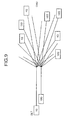
Fig. 9 is a diagram for explaining a configuration example of a communications system without a mixed 1-Gbps and 10-Gbps communication systems environment. As depicted inFig. 9 , in a first configuration example, the 1-Gbps communication system and the 10-Gbps communication system are configured independently. A 1-Gbps optical line terminal (OLT) is connected only to 1-Gbps subscriber optical network units (ONUs). A 10-Gbps optical line terminal is connected only to 1-Gbps optical network units. -
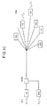
Fig. 10 is a diagram for explaining a first configuration example of a communication system having a mixed 1-Gbps and 10-Gbps communication systems environment. As depicted inFig. 10 , in the first configuration example, the 1-Gbps communication system and the 10-Gbps communication system are mixed through wavelength division multiplexing (WDM). -
Fig. 11 is a diagram for explaining a second configuration example of a communication system having a mixed 1-Gbps and 10-Gbps communication systems environment. As depicted inFig. 11 , in the second communication example, the 1-Gbps communication system and the 10-Gbps communication system are mixed through time division multiple access (TDMA). -
Fig. 12 is a diagram for explaining a third configuration example (downlinks) of a communication system having a mixed 1-Gbps and 10-Gbps communication systems environment. As depicted inFig. 12 , in the third configuration example, the 1-Gbps communication system and the 10-Gbps communication system are mixed through WDM for downlinks fromOLTs optical network units - Optical signals from the 1-Gbps
optical line terminal 1242 and 10-Gbpsoptical line terminal 1245 are transferred through WDM via abranching unit 1241 and atransmission line 1230, and are transmitted by abranching unit 1220 to the 1-Gbpsoptical network unit 1211 and the 10-Gbpsoptical network unit 1212. Among the optical signals output from thebranching unit 1220, theoptical network unit 1211 and theoptical network unit 1212 receive only signals of optical wavelengths allocated thereto, respectively, according to system speed. -
Fig. 13 is a diagram for explaining the third configuration example (uplinks) of a communication system having a mixed 1-Gbps and 10-Gbps communication systems environment. As depicted inFig. 13 , in the third configuration example, the 1-Gbps communication system and the 10-Gbps communication system are mixed through TDMA for uplinks from theOLTs optical network units - The
optical network units optical network unit 1211 and theoptical network unit 1212 are transferred through TDMA via thebranching unit 1220 and thetransmission line 1230, and are transmitted by thebranching unit 1241 to theOLTs branching unit 1241, theoptical line terminal -
- Patent Document 1: Japanese Laid-Open Patent Application Publication No.
H8-8954 - Nonpatent Literature 1: Tanaka, Kenji, "Backward Compatibility", 10 Gb/s PHY for EPON sturdy Group IEEE 802.3 Interim Meeting Austin, TX, Presentation Materials, [online], May 24 to 25, 2006, KDDI R&D Laboratories Inc. [searched on November 29, 2006], Internet <URL:http://grouper.ieee.org/groups/802/3/10GEPON_study/pub lic/may06/tanaka_1_0506.pdf
- However, the conventional technique depicted in
Figs. 12 and 13 cause optical coupler branch loss at the branching unit 1241 (>3 dB) in both the 1-Gbps communication system and the 10-Gbps communication system, which leads to a problem in that the existing loss budget cannot be maintained for the 1-Gbps communication system or the 10-Gbps communication system. - Particularly in the 1-Gbps communication system, apparatuses that are currently being introduced have no loss budget margin, and when migration to the 10-Gbps communication system takes place, the apparatuses cannot be operated due to optical coupler branching loss. Thus, a problem further arises in that the system requires fundamental restructuring such as increasing optical output from a cable plant, reducing the capacity for accommodation of subscribers in the 1-Gbps communication system, etc.
- In light of the foregoing, an object of the present invention is to provide an optical line terminal that, even if a communication system of a different bit rate is migrated to at a cable plant in an existing low-speed communication system, can maintain the loss budget for the low-speed communication system.
- To solve the problems above and achieve an objective, an optical line terminal according to the present invention receives an optical signal transmitted by time division multiple access from plural optical network units among which are an optical network unit for conducting communications at a predetermined bit rate and an optical network unit for conducting communications at a bit rate different from the predetermined bit rate. The optical line terminal includes a branching unit that branches the optical signal at an asymmetrical branching ratio; a first receiving unit that receives, among optical signal branches of a greater branched proportion branched by the branching unit, an optical signal branch of the predetermined bit rate; and a second receiving unit that receives, among optical signal branches of a lesser branched proportion branched by the branching unit, an optical signal branch of the bit rate different from the predetermined bit rate.
- According to the foregoing configuration, the branching unit branches an optical signal at an asymmetrical branching ratio, and an optical signal branch of a greater branched proportion is transmitted from the branching unit to the first receiving unit, thereby restraining intensity loss in an existing communication system.
- Further, an optical line terminal according to the present invention receives an optical signal transmitted by time division multiple access from plural optical network units among which are an optical network unit for conducting communications at a predetermined bit rate and an optical network unit for conducting communications at a bit rate different from the predetermined bit rate. The optical line terminal includes a path switching unit that outputs the optical signal to either a first path or a second path; a first receiving unit that receives the optical signal output to the first path; a second receiving unit that receives the optical signal output to the second path; and a control unit that controls the path switching unit such that the path switching unit outputs an optical signal of the predetermined bit rate to the first path and outputs an optical signal of the bit rate different from the predetermined bit rate to the second path.
- According to the foregoing configuration, the path switching unit outputs the optical signal of a predetermined bit rate to the first receiving unit, and outputs the optical signal of a bit rate different from the predetermined bit rate to the second receiving unit, thereby restraining intensity loss in the existing communication system.
- Moreover, an optical line terminal according to the present invention receives an optical signal transmitted by time division multiple access from plural optical network units among which are an optical network unit for conducting communications at a predetermined bit rate and an optical network unit for conducting communications at a bit rate different from the predetermined bit rate. The optical line terminal includes an optoelectric converting unit that converts the optical signal into an electrical signal; a branching unit that branches the electrical signal converted by the optoelectric converting unit into two respective electrical signals; a first receiving unit that receives, among the electrical signals branched by the branching unit, an electrical signal of the predetermined bit rate; and a second receiving unit that receives, among the electrical signals branched by the branching unit, an electrical signal of the bit rate different from the predetermined bit rate.
- According to the foregoing configuration, the transmitted optical signal is not branched as it is, but is converted into an electrical signal by the optoelectric converting unit, and then the electrical signal is branched, thereby restraining intensity loss in the existing communication system.
- The optical line terminal according to the present invention maintains the loss budget for an existing communication system even when a communication system of a different bit rate is migrated to at a cable plant of the existing communication system.
-
-
Fig. 1 is a block diagram for explaining a basic configuration of a communication system in which an optical line terminal according to a first embodiment is employed; -
Fig. 2 is a block diagram for explaining a specific configuration of a communication system in which the optical line terminal according to the first embodiment is employed; -
Fig. 3 is a block diagram for explaining another specific configuration of a communication system in which the optical line terminal according to the first embodiment is employed; -
Fig. 4 is a block diagram for explaining a basic configuration of a communication system in which an optical line terminal according to a second embodiment is employed; -
Fig. 5 is a block diagram for explaining a specific configuration of a communication system in which the optical line terminal according to the second embodiment is employed; -
Fig. 6 is a block diagram for explaining a basic configuration of a communication system in which an optical line terminal according a third embodiment is employed; -
Fig. 7 is a flowchart for explaining operation of the optical line terminal according to the third embodiment; -
Fig. 8 is a block diagram for explaining a specific configuration of a communication system in which the optical line terminal according to the third embodiment is employed; -
Fig. 9 is a diagram for explaining a configuration example of a communication system without a mixed 1-Gbps and 10-Gbps communication systems environment; -
Fig. 10 is a diagram for explaining a first configuration example of a communication system having a mixed 1-Gbps and 10-Gbps communication systems environment; -
Fig. 11 is a diagram for explaining a second configuration example of a communication system having a mixed 1-Gbps and 10-Gbps communication systems environment; -
Fig. 12 is a diagram for explaining a third configuration example (downlinks) of a communication system having a mixed 1-Gbps and 10-Gbps communication systems environment; and -
Fig. 13 is a diagram for explaining the third configuration example (uplinks) of a communication system having a mixed 1-Gbps and 10-Gbps communication systems environment. -
- 100
- Communication system
- 110
- Optical network unit
- 120, 141
- Branching unit
- 130
- Transmission line
- 140
- Optical line terminal
- 142, 210, 620
- Low-speed communicating unit
- 143, 225
- Amplifying unit
- 144
- Filtering unit
- 145, 220, 630
- High-speed communicating unit
- 146
- Control unit
- 211, 221
- Multiplexing and demultiplexing unit
- 212
- Low-speed receiver
- 213
- Low-speed data processing unit
- 214
- Low-speed transmitter
- 222
- High-speed receiver
- 223
- High-speed data processing unit
- 224
- High-speed transmitter
- 310, 320
- Multiplexing and demultiplexing unit
- 401
- Optical switch
- 610
- Optoelectric converting unit
- 611
- APD
- 612
- APD bias unit
- 613
- TIA
- 614
- AGC
- Preferred embodiments of an optical line terminal according to the present invention will be explained with reference to the accompanying drawings.
-
-
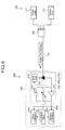
Fig. 1 is a block diagram for explaining a basic configuration of a communication system in which an optical line terminal according to a first embodiment is employed. As depicted inFig. 1 , acommunication system 100 is a PON that includes pluraloptical network units 110, a branchingunit 120, atransmission line 130, and anoptical line terminal 140. - The
communication system 100 has a mixture of communication systems of different bit rates. With regard to this arrangement, migration of a 10-Gbps communication system to an existing 1-Gbps communication system will be explained. In thecommunication system 100, communication systems of different bit rates are mixed through TDMA for an uplink from theoptical network unit 110 to theoptical line terminal 140. - The
optical network units 110 include a low-speed optical network unit (1-Gbps ONU) 111 that conducts communications at a low bit rate (a predetermined bit rate) and a high-speed optical network unit (10-Gbps ONU) 112 that conducts communications at a high bit rate (a bit rate different from the predetermined bit rate). The predetermined bit rate here refers to 1 Gbps, and the bit rate different from the predetermined bit rate here refers to 10 Gbps. - The
optical network units 110 transmit optical signals within respective time frames allocated thereto, based on information concerning TDMA transmission received from theoptical line terminal 140. The branchingunit 120 transmits the optical signals from theoptical network units 110 to theoptical line terminal 140 via thetransmission line 130. - The
optical line terminal 140 includes a branchingunit 141, a low-speed communicating unit (1-Gbps OLT) 142, an amplifyingunit 143, afiltering unit 144, a high-speed communicating unit (10-Gbps OLT) 145, and acontrol unit 146. The branchingunit 141 branches the optical signals transmitted from theoptical network units 110 via the branchingunit 120 and thetransmission line 130, at an asymmetrical branching ratio (intensity ratio) . - For example, the branching
unit 141 branches an optical signal at a branching ratio of 1:10. Among the branched optical signals, the branchingunit 141 outputs an optical signal of a greater branched proportion to the low-speed communicating unit 142, and outputs an optical signal of a lesser branched proportion to the high-speed communicating unit 145. The branching ratio may range from about 1:5 to 1:15, for example, to maintain the intensity of the optical signal output to the low-speed communicating unit 142. - Among the optical signals of a greater branched proportion output from the branching
unit 141, the low-speed communicating unit 142 receives optical signals of a lower bit rate (1 Gbps here). The amplifyingunit 143 amplifies, as appropriate, optical signals in a lesser branched proportion output from the branchingunit 141. The amplifyingunit 143 outputs the amplified optical signals to thefiltering unit 144. The amplifyingunit 143 here is constituted by a semiconductor optical amplifier (SOA). - The
filtering unit 144 removes ASE noise from the optical signals output from the amplifyingunit 143. Thefiltering unit 144 then outputs the optical signals from which ASE noise has been removed, to the high-speed communicating unit 145. The high-speed communicating unit 145 receives, among the optical signals of a greater branched proportion output from thefiltering unit 144, optical signals of a higher bit rate (10 Gbps here). - The
control unit 146 has a function of dynamic bandwidth allocation (DBA) for controlling TDMA in a PON, and allocates time frames for signal transmission to all the optical network units connected to the network. Thecontrol unit 146 controls the low-speed communicating unit 142 and the high-speed communicating unit 145 so as to receive optical signals transmitted through time division multiple access from theoptical network units 110, according to the corresponding speeds of the optical signals. -
Fig. 2 is a block diagram for explaining a specific configuration of a communication system in which the optical line terminal According to the first embodiment is employed. InFig. 2 , constituent elements identical to those in thecommunication system 100 depicted inFig. 1 are given the same reference numerals as those in thecommunication system 100 depicted inFig. 1 , and explanation thereof will be omitted. As depicted inFig. 2 , theoptical line terminal 140 includes the branchingunit 141, a low-speed communicating unit 210, a high-speed communicating unit 220, and thecontrol unit 146. The low-speed communicating unit 210 includes a multiplexing anddemultiplexing unit 211, a low-speed receiver 212, a low-speeddata processing unit 213, and a low-speed transmitter 214. - The multiplexing and
demultiplexing unit 211 outputs an optical signal from the branching unit 141 (uplink) to the low-speed receiver 212. The multiplexing anddemultiplexing unit 211 further outputs an optical signal from the low-speed transmitter 214 (downlink) to the branchingunit 141. Since the optical signal output from the low-speed transmitter 214 and the optical signal output from the branchingunit 141 are different in wavelength, the multiplexing anddemultiplexing unit 211 switches between paths for the optical signals through filtering according to wavelength. - The low-
speed receiver 212 receives an optical signal output from the multiplexing anddemultiplexing unit 211, and converts the received optical signal into an electrical signal. The low-speed receiver 212 outputs the converted electrical signal to the low-speeddata processing unit 213. The low-speed data processing unit (1-Gbps media access control (MAC)) 213 demodulates the electrical signal output from the low-speed receiver 212 into a received data signal, and subjects the signal to data processing such as error correction. - The low-speed
data processing unit 213, under the control of thecontrol unit 146, also modulates a transmitted data signal into a 1-Gbps electrical signal and outputs the modulated electrical signal to the low-speed transmitter 214. The low-speed transmitter 214 converts the electrical signal output from the low-speeddata processing unit 213 into an optical signal, and transmits the optical signal to the multiplexing anddemultiplexing unit 211. - The high-
speed communicating unit 220 includes a multiplexing anddemultiplexing unit 221, the amplifyingunit 143, thefiltering unit 144, a high-speed receiver 222, a high-speeddata processing unit 223, a high-speed transmitter 224, and anamplifying unit 225. The multiplexing anddemultiplexing unit 221 outputs an optical signal from the branchingunit 141 to the high-speed receiver 222 via theamplifying unit 143 and thefiltering unit 144. The multiplexing anddemultiplexing unit 221 further outputs an optical signal from the amplifyingunit 225 to the branchingunit 141. - The high-
speed receiver 222 receives an optical signal output from the multiplexing anddemultiplexing unit 221 via theamplifying unit 143 and thefiltering unit 144, and converts the received optical signal into an electrical signal. The high-speed receiver 222 outputs the converted electrical signal to the high-speeddata processing unit 223. The high-speed data processing unit (10-Gbps MAC) 223 demodulates the electrical signal output from the high-speed receiver 222 into a received data signal, and subjects the signal to data processing such as error correction. - The high-speed
data processing unit 223 also modulates a transmitted data signal into a 10-Gbps electrical signal under control of thecontrol unit 146, and outputs the modulated electrical signal to the high-speed transmitter 224. The high-speed transmitter 224 convert the electrical signal output from the high-speeddata processing unit 223 into an optical signal, and transmits the optical signal to theamplifying unit 225. The high-speeddata processing unit 223 transmits an electrical signal different in wavelength from the optical signal transmitted from the low-speed transmitter 214. - The amplifying
unit 225 amplifies, as appropriate, an optical signal transmitted from the high-speed transmitter 224, and outputs the optical signal to the multiplexing anddemultiplexing unit 221. Thecontrol unit 146 controls the low-speeddata processing unit 213 and the high-speeddata processing unit 223 so as to receive an optical signal transmitted through time division multiple access. Thecontrol unit 146 also controls the low-speeddata processing unit 213 and the high-speeddata processing unit 223 so as to output transmitted data. -
Fig. 3 is a block diagram for explaining another specific configuration of a communication system in which the optical line terminal according to the first embodiment is employed. InFig. 3 , constituent elements identical to those in thecommunication system 100 depicted inFig. 1 or2 are given the same reference numerals as those in thecommunication system 100 depicted inFig. 1 or2 , and explanation thereof will be omitted. As depicted inFig. 3 , theoptical line terminal 140 includes a multiplexing anddemultiplexing unit 310, the branchingunit 141, the low-speed receiver 212, the low-speeddata processing unit 213, the low-speed transmitter 214, the amplifyingunit 143, thefiltering unit 144, the high-speed receiver 222, the high-speeddata processing unit 223, the high-speed transmitter 224, a multiplexing anddemultiplexing unit 320, and thecontrol unit 146. - The multiplexing and
demultiplexing unit 310 outputs to the branchingunit 141, optical signals transmitted from theoptical network units 110 via the branchingunit 120 and thetransmission line 130. The multiplexing anddemultiplexing unit 310 further transmits an optical signal output from the multiplexing anddemultiplexing unit 320, to theoptical network units 110 via thetransmission line 130 and the branchingunit 120. - The branching
unit 141 branches an optical signal output from the multiplexing anddemultiplexing unit 310. Among the branched optical signals, the branchingunit 141 outputs an optical signal of a greater branched proportion to the low-speed receiver 212. In addition, among the branched optical signals, the branchingunit 141 outputs an optical signal of a lesser branched proportion to the high-speed receiver 222 via theamplifying unit 143 and thefiltering unit 144. - The low-
speed transmitter 214 converts an electrical signal output from the low-speeddata processing unit 213 into an optical signal, and outputs the optical signal to the multiplexing anddemultiplexing unit 320. The high-speed transmitter 224 converts an electrical signal output from the high-speeddata processing unit 223, into an optical signal, and outputs the optical signal to the multiplexing anddemultiplexing unit 320. The multiplexing anddemultiplexing unit 320 performs wavelength multiplexing on optical signals output from the low-speeddata processing unit 213 and from the high-speed transmitter 224. The multiplexing anddemultiplexing unit 320 outputs the wavelength-multiplexed optical signal to the multiplexing anddemultiplexing unit 310. - As described above, according to the
optical line terminal 140 of the first embodiment, the branchingunit 141 branches an optical signal at an asymmetrical branching ratio such that an optical signal of a greater branched proportion is branched and transmitted from the branchingunit 141 to the low-speed receiver 212, thereby restraining intensity loss in the low-speed communication system. Accordingly, even if a high-speed communication system is migrated to a cable plant of an existing low-speed communication system, it is possible to maintain the loss budget for the low-speed communication system. - In addition, the amplifying
unit 143 amplifies an optical signal branched from the branchingunit 141 to the high-speed receiver 222, thereby maintaining the intensity of the optical signal branched to the high-speed receiver 222. Further, thefiltering unit 144 transmits the optical signal amplified by the amplifyingunit 143, thereby removing ASE noise generated at the amplifyingunit 143. This makes it possible to maintain the signal noise ratio (SNR) of the optical signal branched from the branchingunit 141 to the high-speed receiver 222. -
Fig. 4 is a block diagram for explaining a basic configuration of a communication system in which an optical line terminal according to a second embodiment is employed. InFig. 4 , constituent elements identical to those in thecommunication system 100 depicted inFig. 1 are given the same reference numerals as those in thecommunication system 100 depicted inFig. 1 , and explanation thereof will be omitted. As depicted inFig. 4 , theoptical line terminal 140 in the second embodiment includes anoptical switch 401 in place of the branchingunit 141 of theoptical line terminal 140 according to the first embodiment. - The
optical switch 401 outputs optical signals transmitted from theoptical network units 110 via the branchingunit 120 and thetransmission line 130, to either the high-speed communicating unit 145 or the low-speed communicating unit 142, under control of thecontrol unit 146. Thecontrol unit 146 controls theoptical switch 401 so as to output a 1-Gbps optical signal to the low-speed communicating unit 142 and to output a 10-Gpbs optical signal to the high-speed communicating unit 145, based on time division multiple access information. -
Fig. 5 is a block diagram for explaining a specific configuration of a communication system in which the optical line terminal according to the second embodiment is employed. InFig. 5 , constitutional elements identical to those in thecommunication system 100 depicted inFigs. 3 and4 are given the same reference numerals as those in thecommunication system 100 depicted inFigs. 3 and4 , and explanation thereof will be omitted. As depicted inFig. 5 , theoptical line terminal 140 includes theoptical switch 401 in place of the branchingunit 141 of theoptical line terminal 140 depicted inFig. 3 . - The multiplexing and
demultiplexing unit 310 outputs optical signals transmitted from theoptical network units 110 via the branchingunit 120 and thetransmission line 130, to theoptical switch 401. Theoptical switch 401 outputs optical signals transmitted from theoptical network units 110 via the branchingunit 120 and thetransmission line 130, to either the low-speed receiver 212 or the high-speed receiver 222, under control of thecontrol unit 146. - The
control unit 146 controls theoptical switch 401 so as to output a 1-Gbps optical signal to the low-speed receiver 212 and to output a 10-Gbps optical signal to the high-speed receiver 222, based on time division multiple access information. - As described above, according to the
optical line terminal 140 of the second embodiment, theoptical switch 401 outputs a 1-Gbps optical signal to the low-speed receiver 212 and outputs a 10-Gbps optical signal to the high-speed receiver 222, thereby restraining intensity loss in the low-speed communication system. Accordingly, even if a high-speed communication system is migrated to a cable plant of an existing low-speed communication system, it is possible to maintain the loss budget for the low-speed communication system. -
Fig. 6 is a block diagram for explaining a basic configuration of a communication system in which an optical line terminal according a third embodiment is employed. InFig. 6 , constituent elements identical to those in thecommunication system 100 depicted inFigs. 1 and2 are given the same reference numerals as those in thecommunication system 100 depicted inFigs. 1 and2 , and explanation thereof will be omitted. As depicted inFig. 6 , theoptical line terminal 140 according to the third embodiment includes anoptoelectric converting unit 610, a low-speed communicating unit 620, a high-speed communicating unit 630, and thecontrol unit 146. - The
optoelectric converting unit 610 converts into electrical signals, optical signals transmitted from theoptical network units 110 via the branchingunit 120 and thetransmission line 130. Theoptoelectric converting unit 610 outputs the converted electrical signals to the low-speed communicating unit 620 and the high-speed communicating unit 630, respectively. The branchingunit 640 branches the electrical signals output from theoptoelectric converting unit 610, and outputs the branched electrical signals to the low-speed communicating unit 620 and the high-speed communicating unit 630, respectively. The branchingunit 640 is not a specific device but a wiring connection. - Specifically, the
optoelectric converting unit 610 includes an avalanche photo diode (APD) 611, anAPD bias unit 612, a trans-impedance amplifier (TIA) 613, and an auto-gain control unit (AGC) 614. - The
APD 611 converts into electrical signals, optical signals transmitted from theoptical network units 110 via the branchingunit 120 and thetransmission line 130. TheAPD 611 outputs the converted electrical signals to theTIA 613. TheAPD bias unit 612 applies a bias voltage to theAPD 611. TheAPD bias unit 612 controls the value of the bias voltage applied to theAPD 611 under control of thecontrol unit 146, thereby changing gain or bandwidth in theAPD 611. - The
TIA 613 amplifies the electrical signal output from theAPD 611. TheTIA 613 outputs the amplified electrical signal to the low-speed communicating unit 620 and the high-speed communicating unit 630, respectively. TheAGC 614 automatically controls gain or bandwidth in theTIA 613. TheAGC 614 also changes at least one of gain and bandwidth in theTIA 613 under control of thecontrol unit 146. Thecontrol unit 146 controls at least one of gain and bandwidth in theoptoelectric converting unit 610, based on time division multiple access information. - Specifically, the
control unit 146 controls at least one of theAGC 614 and theAPD bias unit 612, such that, when theoptical line terminal 140 receives a 1-Gbps optical signal, gain in theoptoelectric converting unit 610 becomes larger than gain in the case of receiving a 10-Gbps optical signals. Thecontrol unit 146 further controls at least one of theAGC 614 and theAPD bias unit 612, such that, when theoptical line terminal 140 receives a 10-Gbps optical signal, gain in theoptoelectric converting unit 610 becomes smaller than gain in the case of receiving a 1-Gbps optical signal. - The
control unit 146 further controls at least one of theAGC 614 and theAPD bias unit 612, such that, when theoptical line terminal 140 receives a 1-Gbps optical signal, a bandwidth in theoptoelectric converting unit 610 becomes narrower than a bandwidth in the case of receiving a 10-Gbps optical signal. Thecontrol unit 146 controls at least one of theAGC 614 and theAPD bias unit 612, such that, when theoptical line terminal 140 receives a 10-Gbps optical signal, a bandwidth in theoptoelectric converting unit 610 becomes narrower than a bandwidth in the case of receiving a 1-Gbps optical signal. -
Fig. 7 is a flowchart for explaining operation of the optical line terminal according to the third embodiment. As depicted inFig. 7 , thecontrol unit 146 determines whether an optical signal to be received next is a 1-Gbps optical signal, based on time division multiple access information (step S701). If the optical signal to be received next is a 1-Gbps optical signal (step S701: YES), thecontrol unit 146 sets a narrow bandwidth and a large gain in the optoelectric converting unit 610 (step S702), and the process proceeds to step S704. - If the
control unit 146 determines at step S701 that the optical signal to be received next is a 10-Gbps optical signal (step S701: NO), thecontrol unit 146 sets a wide bandwidth and a small gain in the optoelectric converting unit 610 (step S703), and the process proceeds to step S704. Thecontrol unit 146 begins reception of the optical signal (step S704), and activates theAGC 614 within the ranges of values set at steps S702 or S703 (step S705). - Next, the
control unit 146 determines whether reception of the optical signal is to be terminated (step S706). If thecontrol unit 146 determines that reception of the optical signal is not to be terminated (step S706: NO), thecontrol unit 146 returns to step S701, and the process continues. If thecontrol unit 146 determines at step S706 that reception of the optical signal is to be terminated (step S706: YES), a series of the process ends. -
Fig. 8 is a block diagram for explaining a specific configuration of a communication system in which the optical line terminal according to the third embodiment is employed. InFig. 8 , constituent elements identical to those in thecommunication system 100 depicted inFigs. 3 and6 are given the same reference numerals as those in thecommunication system 100 depicted inFigs. 3 and6 , and explanation thereof will be omitted. As depicted inFig. 8 , theoptical line terminal 140 includes the multiplexing anddemultiplexing unit 310, theoptoelectric converting unit 610, the low-speed communicating unit 620, the low-speed transmitter 214, the high-speed communicating unit 630, the high-speed transmitter 224, the multiplexing anddemultiplexing unit 320, and thecontrol unit 146. - The multiplexing and
demultiplexing unit 310 outputs to theoptoelectric converting unit 610, optical signals transmitted from theoptical network units 110 via the branchingunit 120 and thetransmission line 130. The low-speed communicating unit 620 modulates transmitted data into a 1-Gbps electrical signal, and outputs the modulated electrical signal to the low-speed transmitter 214. The high-speed communicating unit 630 modulates transmitted data into a 10-Gbps electrical signal, and outputs the modulated electrical signal to the high-speed transmitter 224. - As described above, according to the
optical line terminal 140 of the third embodiment, theoptoelectric converting unit 610 converts a transmitted optical signal into an electrical signal, and then the branchingunit 640 branches the electrical signal, thereby restraining intensity loss in the low-speed communication system associated with signal branching. Accordingly, even if a high-speed communication system is migrated to a cable plant of an existing low-speed communication system, the loss budget for the low-speed communication system can be maintained. - As explained above, according to the optical line terminal of the present embodiments, even if a communication system of a different bit rate is migrated to a cable plant of an existing communication system, the loss budget of the existing communications system can be maintained. Thus, a communication system of a different bit rate can be migrated without fundamental restructuring of the existing communication system.
- In the foregoing embodiments, a 10-Gbps communication system is migrated to an existing 1-Gbps communication system; however, the present invention is not limited to this arrangement, and can be generally applied to cases where a communication system of a different bit rate is migrated.
- As described above, the optical line terminal of the present invention is useful with respect to a communication system that includes a mixture of communication systems of different speeds, and is particularly applicable to an arrangement where a high-speed communication system is migrated to an existing low-speed communication system.
Claims (12)
- An optical line terminal that receives an optical signal transmitted by time division multiple access from a plurality of optical network units among which are an optical network unit for conducting communications at a predetermined bit rate and an optical network unit for conducting communications at a bit rate different from the predetermined bit rate, the optical line terminal comprising:a branching unit that branches the optical signal at an asymmetrical branching ratio;a first receiving unit that receives, among optical signal branches of a greater branched proportion branched by the branching unit, an optical signal branch of the predetermined bit rate; anda second receiving unit that receives, among optical signal branches of a lesser branched proportion branched by the branching unit, an optical signal branch of the bit rate different from the predetermined bit rate.
- The optical line terminal according to claim 1, further comprising an amplifying unit that amplifies the optical signal at a lesser branched proportion branched by the branching unit.
- The optical line terminal according to claim 2, further comprising a filtering unit that removes ASE noise from the optical signal amplified by the amplifying unit.
- An optical line terminal that receives an optical signal transmitted by time division multiple access from a plurality of optical network units among which are an optical network unit for conducting communications at a predetermined bit rate and an optical network unit for conducting communications at a bit rate different from the predetermined bit rate, the optical line terminal comprising:a path switching unit that outputs the optical signal to either a first path or a second path;a first receiving unit that receives the optical signal output to the first path;a second receiving unit that receives the optical signal output to the second path; anda control unit that controls the path switching unit such that the path switching unit outputs an optical signal of the predetermined bit rate to the first path and outputs an optical signal of the bit rate different from the predetermined bit rate to the second path.
- The optical line terminal according to claim 4, further comprising an acquiring unit that acquires information concerning time division multiple access, wherein the control unit controls the path switching unit based on the information concerning time division multiple access.
- An optical line terminal that receives an optical signal transmitted by time division multiple access from a plurality of optical network units among which are an optical network unit for conducting communications at a predetermined bit rate and an optical network unit for conducting communications at a bit rate different from the predetermined bit rate, the optical line terminal comprising:an optoelectric converting unit that converts the optical signal into an electrical signal;a branching unit that branches the electrical signal converted by the optoelectric converting unit into two respective electrical signals;a first receiving unit that receives, among the electrical signals branched by the branching unit, an electrical signal of the predetermined bit rate; anda second receiving unit that receives, among the electrical signals branched by the branching unit, an electrical signal of the bit rate different from the predetermined bit rate.
- The optical line terminal according to claim 6, further comprising:an acquiring unit that acquires information concerning time division multiple access; anda control unit that controls at least one of gain and a bandwidth in the optoelectric converting unit, based on the information concerning time division multiple access.
- The optical line terminal according to claim 7, wherein the control unit controls the bandwidth in the optoelectric converting unit so as to become narrower than when an optical signal of a higher bit rate is received when, among the optical signal of the predetermined bit rate and the optical signal of the bit rate different from the predetermined bit rate, the optical signal of a lower bit rate is received.
- The optical line terminal according to claim 7, wherein the control unit controls the gain in the optoelectric converting unit so as to become larger than when an optical signal of a higher bit rate is received when, among the optical signal of the predetermined bit rate and the optical signal of the bit rate different from the predetermined bit rate, the optical signal of a lower bit rate is received.
- The optical line terminal according to any one of claims 7 to 9, wherein
the optoelectric converting unit comprises:an optoelectric converting element that converts the optical signal into an electrical signal, andan amplifier that amplifies the electrical signal optoelectrically converted by the optoelectric converting element. - The optical line terminal according to claim 10, wherein the control unit controls at least one of gain and bandwidth in the amplifier.
- The optical line terminal according to claim 10, wherein the control unit controls at least one of gain value and bandwidth in the optoelectric converting element.
Applications Claiming Priority (1)
| Application Number | Priority Date | Filing Date | Title |
|---|---|---|---|
| PCT/JP2006/324008 WO2008068811A1 (en) | 2006-11-30 | 2006-11-30 | Station-side terminator |
Publications (2)
| Publication Number | Publication Date |
|---|---|
| EP2088696A1 true EP2088696A1 (en) | 2009-08-12 |
| EP2088696A4 EP2088696A4 (en) | 2015-12-30 |
Family
ID=39491732
Family Applications (1)
| Application Number | Title | Priority Date | Filing Date |
|---|---|---|---|
| EP06833811.0A Withdrawn EP2088696A4 (en) | 2006-11-30 | 2006-11-30 | TERMINATION SYSTEM OF POST SIDE |
Country Status (6)
| Country | Link |
|---|---|
| US (1) | US8238753B2 (en) |
| EP (1) | EP2088696A4 (en) |
| JP (1) | JP4820880B2 (en) |
| KR (1) | KR101039181B1 (en) |
| CN (1) | CN101542945B (en) |
| WO (1) | WO2008068811A1 (en) |
Cited By (1)
| Publication number | Priority date | Publication date | Assignee | Title |
|---|---|---|---|---|
| EP4351041A4 (en) * | 2021-06-18 | 2025-04-30 | ZTE Corporation | OPTICAL SIGNAL RECEIVING APPARATUS, SYSTEM AND METHOD, OPTICAL LINE TERMINAL AND COMPUTER READABLE RECORDING MEDIUM |
Families Citing this family (23)
| Publication number | Priority date | Publication date | Assignee | Title |
|---|---|---|---|---|
| US20080267625A1 (en) * | 2007-04-30 | 2008-10-30 | Futurewei Technologies, Inc. | Multi-Rate Multi-Wavelength Optical Burst Detector |
| JP2009077323A (en) * | 2007-09-25 | 2009-04-09 | Hitachi Communication Technologies Ltd | Station side optical communication apparatus and optical communication system |
| CN101420412B (en) * | 2007-10-24 | 2012-12-19 | 华为技术有限公司 | Signal processing method, system and optical line terminal |
| JP5220662B2 (en) * | 2009-03-10 | 2013-06-26 | 富士通テレコムネットワークス株式会社 | PON system |
| JP5347674B2 (en) * | 2009-04-15 | 2013-11-20 | 富士通株式会社 | Relay device, signal processing device, and optical communication system |
| CN102422574B (en) * | 2009-04-23 | 2016-06-29 | 骁阳网络有限公司 | Method and device for data processing |
| US8983308B2 (en) * | 2009-09-22 | 2015-03-17 | Calix, Inc. | Optical network device with multi-transport support |
| JP5399932B2 (en) * | 2010-01-28 | 2014-01-29 | 日本電信電話株式会社 | Optical receiver and optical transmitter / receiver |
| CN103125095B (en) * | 2010-08-10 | 2015-07-29 | 富士通通讯网络株式会社 | Base station side device and pon system |
| JP5669613B2 (en) * | 2011-02-18 | 2015-02-12 | 沖電気工業株式会社 | Dynamic bandwidth allocation method, optical communication network, and station side apparatus |
| US8553551B2 (en) * | 2011-06-12 | 2013-10-08 | Oliver Solutions Ltd. | Dynamic bandwidth allocation for upstream transmission in passive optical networks |
| JP5651548B2 (en) * | 2011-06-30 | 2015-01-14 | 株式会社日立製作所 | Station side equipment, optical network system |
| JP5941150B2 (en) * | 2011-09-08 | 2016-06-29 | オーエフエス ファイテル,エルエルシー | Configuration for coexisting GPON and XGPON optical communication systems |
| JP2013219599A (en) * | 2012-04-10 | 2013-10-24 | Nippon Telegr & Teleph Corp <Ntt> | Multirate optical signal receiving device and method |
| US10079642B2 (en) * | 2013-01-02 | 2018-09-18 | Renesas Electronics America Inc. | Transporting multiple low-speed data streams across a high-speed communication link |
| CN103475415A (en) * | 2013-09-25 | 2013-12-25 | 武汉世翔科技有限公司 | Method for transmitting optical module low-speed signals |
| US9300427B2 (en) * | 2013-09-30 | 2016-03-29 | Broadcom Corporation | Upstream scheduling in a passive optical network |
| WO2015141061A1 (en) * | 2014-03-20 | 2015-09-24 | 日本電信電話株式会社 | Transport apparatus and transport method |
| JP6365349B2 (en) * | 2015-03-04 | 2018-08-01 | 住友電気工業株式会社 | Data receiver |
| EP3550740B1 (en) | 2016-12-28 | 2022-02-23 | Huawei Technologies Co., Ltd. | Transmission optical assembly, optical device, optical module, and passive optical network system |
| JP6691155B2 (en) * | 2018-02-27 | 2020-04-28 | ファナック株式会社 | Optical communication system and optical transmission module |
| CN115499730A (en) * | 2021-06-18 | 2022-12-20 | 中兴通讯股份有限公司 | Optical signal receiving device, terminal and system |
| CN117528294A (en) * | 2022-07-30 | 2024-02-06 | 华为技术有限公司 | A device for amplifying signals, a device and method for receiving optical signals |
Family Cites Families (22)
| Publication number | Priority date | Publication date | Assignee | Title |
|---|---|---|---|---|
| FR2670639A1 (en) * | 1990-12-14 | 1992-06-19 | Trt Telecom Radio Electr | DEVICE FOR TRANSMITTING DIFFERENT CHANNELS AT A TIME MULTIPLEX WITH VARIOUS BIT RATES. |
| US5329393A (en) * | 1992-10-15 | 1994-07-12 | At&T Bell Laboratories | Optical Nyquist rate multiplexer and demultiplexer |
| FR2710216B1 (en) * | 1993-09-15 | 1995-10-13 | Abiven Jacques | Multi-bit frames for tree-starred telecommunications network. |
| JPH088954A (en) | 1994-06-21 | 1996-01-12 | Nec Corp | Increase system for service capacity in point-multi-point optical transmission system |
| JP3008880B2 (en) * | 1997-03-19 | 2000-02-14 | 日本電気株式会社 | Transmission / reception system |
| JP2000049823A (en) * | 1998-08-03 | 2000-02-18 | Nippon Telegr & Teleph Corp <Ntt> | Transmitter, receiver, and multi-rate transmission system using them |
| JP3299933B2 (en) * | 1998-11-16 | 2002-07-08 | 日本電信電話株式会社 | Optical time division multiplex terminal equipment |
| JP3626365B2 (en) * | 1999-03-05 | 2005-03-09 | 日本電信電話株式会社 | Clock and data recovery circuit |
| US6822975B1 (en) * | 2000-09-08 | 2004-11-23 | Lucent Technologies | Circuitry for mixed-rate optical communication networks |
| US7174106B2 (en) * | 2001-08-13 | 2007-02-06 | Finisar Corporation | Multi-rate and multi-level gigabit interface converter |
| GB0303358D0 (en) * | 2003-02-14 | 2003-03-19 | Marconi Comm Ltd | Optical transmission system |
| JP2005033537A (en) * | 2003-07-14 | 2005-02-03 | Hitachi Communication Technologies Ltd | Passive optical network data transmission method and termination device |
| CN1642042A (en) * | 2004-01-15 | 2005-07-20 | 华为技术有限公司 | Optical communication system, sub-rate multiplex demultiplex and its method |
| EP1717954B1 (en) * | 2004-02-16 | 2012-06-13 | Nippon Telegraph And Telephone Corporation | Bit rate determination circuit based on low bit rate signal |
| JP4417208B2 (en) * | 2004-09-10 | 2010-02-17 | 日本電信電話株式会社 | Optical access system, optical service unit and optical network unit |
| US8712243B2 (en) * | 2004-12-17 | 2014-04-29 | Alcatel Lucent | Methods and apparatus for achieving multiple bit rates in passive optical networks |
| EP1701462B1 (en) * | 2005-03-07 | 2007-06-06 | Alcatel Lucent | Wavelength grid for DWDM |
| JP2007274280A (en) * | 2006-03-31 | 2007-10-18 | Sumitomo Electric Ind Ltd | Station side device, transmission rate switching device, and communication method in PON system |
| JP4315165B2 (en) * | 2006-04-28 | 2009-08-19 | 住友電気工業株式会社 | Station side device and optical receiving circuit |
| JP2007300445A (en) * | 2006-05-01 | 2007-11-15 | Sumitomo Electric Ind Ltd | Station side apparatus and terminal apparatus usable for multi-rate PON system, and network synchronization method in the system |
| JP2008054006A (en) * | 2006-08-24 | 2008-03-06 | Mitsubishi Electric Corp | Transmission frame, transmission device, reception device, communication method, and communication program |
| JP4840027B2 (en) * | 2006-08-28 | 2011-12-21 | 日本電気株式会社 | Station side optical network termination device and optical communication system |
-
2006
- 2006-11-30 KR KR1020097008608A patent/KR101039181B1/en not_active Expired - Fee Related
- 2006-11-30 CN CN2006800564614A patent/CN101542945B/en not_active Expired - Fee Related
- 2006-11-30 EP EP06833811.0A patent/EP2088696A4/en not_active Withdrawn
- 2006-11-30 JP JP2008548106A patent/JP4820880B2/en not_active Expired - Fee Related
- 2006-11-30 WO PCT/JP2006/324008 patent/WO2008068811A1/en not_active Ceased
-
2009
- 2009-03-30 US US12/414,074 patent/US8238753B2/en not_active Expired - Fee Related
Non-Patent Citations (1)
| Title |
|---|
| See references of WO2008068811A1 * |
Cited By (1)
| Publication number | Priority date | Publication date | Assignee | Title |
|---|---|---|---|---|
| EP4351041A4 (en) * | 2021-06-18 | 2025-04-30 | ZTE Corporation | OPTICAL SIGNAL RECEIVING APPARATUS, SYSTEM AND METHOD, OPTICAL LINE TERMINAL AND COMPUTER READABLE RECORDING MEDIUM |
Also Published As
| Publication number | Publication date |
|---|---|
| KR20090086961A (en) | 2009-08-14 |
| US20090190931A1 (en) | 2009-07-30 |
| JP4820880B2 (en) | 2011-11-24 |
| WO2008068811A1 (en) | 2008-06-12 |
| CN101542945A (en) | 2009-09-23 |
| CN101542945B (en) | 2012-05-30 |
| EP2088696A4 (en) | 2015-12-30 |
| US8238753B2 (en) | 2012-08-07 |
| KR101039181B1 (en) | 2011-06-03 |
| JPWO2008068811A1 (en) | 2010-03-11 |
Similar Documents
| Publication | Publication Date | Title |
|---|---|---|
| US8238753B2 (en) | Optical line terminal | |
| CN105323008B (en) | Configuration method and device for optical transceiver module and its working parameters | |
| US7936991B2 (en) | Optical line terminating apparatus and optical communication system | |
| EP2056495A1 (en) | Electrical point-to-multipoint repeater for PON | |
| CN106489245A (en) | Assigned based on the up optical transport of through-put power | |
| CA3057833C (en) | System and methods for coherent pon architecture and burst-mode reception | |
| EP4290789A2 (en) | System and methods for coherent burst reception | |
| US12149339B1 (en) | System and methods for coherent optical extension | |
| EP2285019A1 (en) | Optical communication system, apparatus and method | |
| CN101471730B (en) | Optical fiber wideband access system and optical network unit based on WDM structure | |
| CN114402627B (en) | Port replicator | |
| CN106470075A (en) | OLT optical transceiver integrated module, method and system for processing multiple PONs | |
| US20180213307A1 (en) | Communication Method, Apparatus, and System for Passive Optical Network | |
| US10250331B2 (en) | Subscriber device and light receiving method | |
| EP4557637A1 (en) | Apparatus for amplifying signal, and apparatus and method for receiving optical signal | |
| KR100547721B1 (en) | Optical amplifier module and optical transmission system using same | |
| CN119233130A (en) | Optical module, optical line terminal and signal processing method | |
| Chang | Uplink burst-mode transmissions using EPON physical-layer chipset for broadband optical Ethernet access networks |
Legal Events
| Date | Code | Title | Description |
|---|---|---|---|
| PUAI | Public reference made under article 153(3) epc to a published international application that has entered the european phase |
Free format text: ORIGINAL CODE: 0009012 |
|
| 17P | Request for examination filed |
Effective date: 20090422 |
|
| AK | Designated contracting states |
Kind code of ref document: A1 Designated state(s): AT BE BG CH CY CZ DE DK EE ES FI FR GB GR HU IE IS IT LI LT LU LV MC NL PL PT RO SE SI SK TR |
|
| DAX | Request for extension of the european patent (deleted) | ||
| STAA | Information on the status of an ep patent application or granted ep patent |
Free format text: STATUS: THE APPLICATION HAS BEEN WITHDRAWN |
|
| RA4 | Supplementary search report drawn up and despatched (corrected) |
Effective date: 20151130 |
|
| RIC1 | Information provided on ipc code assigned before grant |
Ipc: H04B 10/2507 20130101ALI20151124BHEP Ipc: H04J 3/16 20060101ALI20151124BHEP Ipc: H04J 3/00 20060101ALI20151124BHEP Ipc: H04L 12/44 20060101ALI20151124BHEP Ipc: H04B 10/00 20130101ALI20151124BHEP Ipc: H04J 14/02 20060101ALI20151124BHEP Ipc: H04J 14/08 20060101AFI20151124BHEP |
|
| 18W | Application withdrawn |
Effective date: 20151214 |