EP2088689A1 - Transmission/reception system and method for a base station of a wireless communication network - Google Patents
Transmission/reception system and method for a base station of a wireless communication network Download PDFInfo
- Publication number
- EP2088689A1 EP2088689A1 EP08305014A EP08305014A EP2088689A1 EP 2088689 A1 EP2088689 A1 EP 2088689A1 EP 08305014 A EP08305014 A EP 08305014A EP 08305014 A EP08305014 A EP 08305014A EP 2088689 A1 EP2088689 A1 EP 2088689A1
- Authority
- EP
- European Patent Office
- Prior art keywords
- transmission
- multipath
- terminal
- antenna
- radiating elements
- Prior art date
- Legal status (The legal status is an assumption and is not a legal conclusion. Google has not performed a legal analysis and makes no representation as to the accuracy of the status listed.)
- Withdrawn
Links
- 238000004891 communication Methods 0.000 title claims abstract description 18
- 230000005540 biological transmission Effects 0.000 title claims description 67
- 238000000034 method Methods 0.000 title claims description 19
- 239000011159 matrix material Substances 0.000 claims description 25
- 238000012546 transfer Methods 0.000 claims description 8
- 230000003044 adaptive effect Effects 0.000 claims description 7
- 238000010586 diagram Methods 0.000 description 10
- 238000005516 engineering process Methods 0.000 description 8
- 238000012545 processing Methods 0.000 description 5
- 230000010267 cellular communication Effects 0.000 description 2
- 238000000354 decomposition reaction Methods 0.000 description 2
- 230000008569 process Effects 0.000 description 2
- 230000015572 biosynthetic process Effects 0.000 description 1
- 230000001413 cellular effect Effects 0.000 description 1
- 230000000295 complement effect Effects 0.000 description 1
- 238000011161 development Methods 0.000 description 1
- 230000009977 dual effect Effects 0.000 description 1
- 238000012854 evaluation process Methods 0.000 description 1
- 230000003993 interaction Effects 0.000 description 1
- 230000004807 localization Effects 0.000 description 1
- 238000012544 monitoring process Methods 0.000 description 1
- 230000000737 periodic effect Effects 0.000 description 1
- 230000007704 transition Effects 0.000 description 1
Images


Classifications
-
- H—ELECTRICITY
- H04—ELECTRIC COMMUNICATION TECHNIQUE
- H04B—TRANSMISSION
- H04B7/00—Radio transmission systems, i.e. using radiation field
- H04B7/02—Diversity systems; Multi-antenna system, i.e. transmission or reception using multiple antennas
- H04B7/04—Diversity systems; Multi-antenna system, i.e. transmission or reception using multiple antennas using two or more spaced independent antennas
- H04B7/06—Diversity systems; Multi-antenna system, i.e. transmission or reception using multiple antennas using two or more spaced independent antennas at the transmitting station
- H04B7/0686—Hybrid systems, i.e. switching and simultaneous transmission
- H04B7/0689—Hybrid systems, i.e. switching and simultaneous transmission using different transmission schemes, at least one of them being a diversity transmission scheme
-
- H—ELECTRICITY
- H04—ELECTRIC COMMUNICATION TECHNIQUE
- H04B—TRANSMISSION
- H04B7/00—Radio transmission systems, i.e. using radiation field
- H04B7/02—Diversity systems; Multi-antenna system, i.e. transmission or reception using multiple antennas
- H04B7/04—Diversity systems; Multi-antenna system, i.e. transmission or reception using multiple antennas using two or more spaced independent antennas
- H04B7/08—Diversity systems; Multi-antenna system, i.e. transmission or reception using multiple antennas using two or more spaced independent antennas at the receiving station
- H04B7/0868—Hybrid systems, i.e. switching and combining
- H04B7/0871—Hybrid systems, i.e. switching and combining using different reception schemes, at least one of them being a diversity reception scheme
-
- H—ELECTRICITY
- H04—ELECTRIC COMMUNICATION TECHNIQUE
- H04B—TRANSMISSION
- H04B7/00—Radio transmission systems, i.e. using radiation field
- H04B7/02—Diversity systems; Multi-antenna system, i.e. transmission or reception using multiple antennas
- H04B7/04—Diversity systems; Multi-antenna system, i.e. transmission or reception using multiple antennas using two or more spaced independent antennas
- H04B7/0413—MIMO systems
-
- H—ELECTRICITY
- H04—ELECTRIC COMMUNICATION TECHNIQUE
- H04B—TRANSMISSION
- H04B7/00—Radio transmission systems, i.e. using radiation field
- H04B7/02—Diversity systems; Multi-antenna system, i.e. transmission or reception using multiple antennas
- H04B7/04—Diversity systems; Multi-antenna system, i.e. transmission or reception using multiple antennas using two or more spaced independent antennas
- H04B7/06—Diversity systems; Multi-antenna system, i.e. transmission or reception using multiple antennas using two or more spaced independent antennas at the transmitting station
- H04B7/0613—Diversity systems; Multi-antenna system, i.e. transmission or reception using multiple antennas using two or more spaced independent antennas at the transmitting station using simultaneous transmission
- H04B7/0615—Diversity systems; Multi-antenna system, i.e. transmission or reception using multiple antennas using two or more spaced independent antennas at the transmitting station using simultaneous transmission of weighted versions of same signal
- H04B7/0617—Diversity systems; Multi-antenna system, i.e. transmission or reception using multiple antennas using two or more spaced independent antennas at the transmitting station using simultaneous transmission of weighted versions of same signal for beam forming
-
- H—ELECTRICITY
- H04—ELECTRIC COMMUNICATION TECHNIQUE
- H04B—TRANSMISSION
- H04B7/00—Radio transmission systems, i.e. using radiation field
- H04B7/02—Diversity systems; Multi-antenna system, i.e. transmission or reception using multiple antennas
- H04B7/04—Diversity systems; Multi-antenna system, i.e. transmission or reception using multiple antennas using two or more spaced independent antennas
- H04B7/08—Diversity systems; Multi-antenna system, i.e. transmission or reception using multiple antennas using two or more spaced independent antennas at the receiving station
- H04B7/0837—Diversity systems; Multi-antenna system, i.e. transmission or reception using multiple antennas using two or more spaced independent antennas at the receiving station using pre-detection combining
- H04B7/0842—Weighted combining
- H04B7/086—Weighted combining using weights depending on external parameters, e.g. direction of arrival [DOA], predetermined weights or beamforming
Definitions
- the invention relates generally to wireless communications, in particular to a transmission/reception system for use in a base station of a wireless communication network and to an associated transmission/reception method.
- WLAN wireless local area network
- fourth generation communication systems in base station use multi antennas systems which can be classified in two families:
- the aim of the present invention is to propose a new transmission/reception system for a base station which associates the advantages of both beamforming/MIMO modes without their corresponding drawbacks.
- a transmission/reception system for use in a base station of a wireless communication network, comprising:
- a base station of a wireless communication network said base station comprising a transmission/reception antenna including an array of radiating elements for exchanging data traffic signals with at least one wireless terminal located in the coverage area of said antenna, characterised in that said method comprises:
- a base station 1 is adapted to exchange signals with at least two terminals T1, T2 using two different antenna diagrams 111, 112.
- base station 1 can be implemented in an urban environment.
- Terminals T1, T2 are located respectively in two sub-areas 11, 12.
- the purpose of the invention is to allow the base station to exchange data traffic either in a MIMO mode or in a beamforming mode with a given terminal depending whether this terminal is located in a multipath rich environment or in a multipath poor environment.
- the transmission/reception system of the invention is adapted to exchange data traffic signals with terminal T1 using a beamforming mode (antenna diagram 111).
- the transmission/reception system of the invention is adapted to exchange data traffic signals using a MIMO mode (antenna diagram 112).
- FIG. 2 A schematic representation of the transmission/reception system for a base station is represented Figure 2 .
- the system classically comprises:
- radiating elements REi of the antenna 2 may also be active elements directly controlled by control module 4.
- transmission/reception system also comprises a determination module 5 adapted to determine in which type of multipath environment (rich or poor) terminals T1, T2 are located and control module 4 is adapted to control transmission/reception of said antenna 2 either in a first beamforming mode, or in a second MIMO mode, depending on the result delivered by determination module 5.
- determination module 5 adapted to determine in which type of multipath environment (rich or poor) terminals T1, T2 are located and control module 4 is adapted to control transmission/reception of said antenna 2 either in a first beamforming mode, or in a second MIMO mode, depending on the result delivered by determination module 5.
- digital processing module 7 is adapted to select the information bits to be transmitted to terminals T1, T2 and to transmit the selected bits to modulation/demodulation module 6 which is adapted to modulate the bits on a baseband signal and to transmit the modulated signal to the transceivers Wi. Then, in accordance with the type of environment in which the terminal is located, determined by determination module 5, control module 4 is adapted to control transceivers Wi so that they correctly supply radiating elements REi according to the transmission mode adapted to the environment in which terminals T1, T2 are located. Radiating elements RE1 transmit then the appropriate signal in the appropriate mode to terminals T1, T2.
- radiating elements REi are adapted to transmit the received signal to transceivers Wi.
- control module 4 is adapted to control transceivers Wi so that they correctly process the received signal according to the reception mode adapted to the environment in which terminals T1, T2 are located.
- transceivers Wi are adapted to transmit the correctly adapted baseband signal to modulation/demodulation module 6, which demodulates the baseband signal in a digital signal.
- the digital signal is then processed by digital processing module 7 to correctly transmit to base station 1 the information bits contained in the data traffic signal emitted by terminals T1, T2.
- control module 4 Operations and interactions between control module 4 and transceiver Wi elements of the transmission/reception system according to the invention will now be described with the help of figures 2 and 3 .
- control module 4 is even more effective than the geometrical aspect of antenna 2 and the disposal of radiating elements REi on antenna 2 are adapted to suit both beamforming mode and MIMO mode. More precisely, the geometrical aspect of antenna 2 and the disposal of radiating elements REi on the array should:
- a specific non-limitative arrangement of an array 20 may comprise sixteen radiating elements REi.
- radiating elements REi must be separated by a distance of half a wavelength ⁇ /2 on the facet.
- wavelengths used in actual fourth generation cellular communication systems have been normalized by the IEEE 802.11b and are around 2.4 GHz.
- distance between two radiating elements may be set to 7 cm.
- antenna 2 can be advantageously square-shaped.
- the numbers of radiating elements disposed vertically and horizontally are thus equal.
- the number of horizontal (respectively vertical) radiating elements REi is proportional to the horizontal (respectively vertical) dimension of antenna 2 and determines the resolution and the width of the horizontal and vertical diagrams of antenna 2.
- the beam generated in the direction settled by the adaptive choice of the weights is even narrower than radiating elements REi are arranged in a symmetrical array.
- control module 4 is adapted to perform the selection so that radiating elements REi forming the subset are selected within array among the most spaced radiating element REi of the array 20.
- the selected radiating elements REi are located, as show in bold on figure 3 , at the four corners.
- the subset of radiating elements REi which is selected to cover zone 12 may be composed of two or three elements. In this case, their position on array 20 of antenna 2 needs also to maximize the distance between each element REi of the subset.
- control module 4 The selection and weighting of radiating elements REi or associated transceivers Wi achieved by control module 4 is now illustrated in the case where radiating elements REi are specifically arranged on a array as shown in figure 3 .
- each radiating elements REi of the array is a passive or active component and is powered by an amplitude-phase law.
- Each component of the antenna represents a complex weighting a i , j of the reference signal.
- control module 4 controls each transceiver Wi so that a complex weighting a i , j k is applied to the received signal S i , j k t of each radiating element REi for each terminal k.
- Each transceiver then generates an a i , j k ⁇ s i , j k t signal.
- weightings performed on the transceiver Wi by control module 2 can be represented by a weighting matrix.
- the value of the matrix is: a 1 , 1 k a i , j k a n , n k ⁇ i , j , a i , j k ⁇ 1
- the a i , j k ⁇ s i , j k t signals are summed up with a beamforming processing mode of control module 4 and the summed signal ⁇ i ⁇ j a i , j k ⁇ s i , j k t is sent to the modulation/demodulation module 6.
- control module 4 performs a selection of subset of radiating elements REi within the array which are identically controlled.
- the four generated signals a max i , j k ⁇ s max i , j k t , a min i , j k ⁇ s min i , j k t , a i , max j k ⁇ s i , max j k t , a i , min j k ⁇ s i , min j k t will be independently processed with a MIMO processing mode of control module 4 and the resulting baseband signal is then sent to modulation/demodulation module 6.
- control module 4 controls each transceiver Wi so that the baseband signal generated by modulation/demodulation module 6 is processed into a i , j k ⁇ s i , j k t signals which are then transmitted to the corresponding radiating element REi.
- antenna 2 transmits the corresponding data traffic signal to terminals T1, T2 with the correct transmission mode.
- the weighting matrix applied to the transmitted/received signal is not necessarily a square matrix. Additionally, the weighting matrix takes into account the fact that the transmission/reception in a MIMO mode may also be done, as already mentioned, with two or three radiating elements REi of array 20.
- antenna 2 With such geometrical aspect of antenna 2 and a disposal of radiating elements REi combined with such a module control 4, it is possible to reduce the volume and cost of a base station 1 which is able to exchange traffic data signals in either a beamforming mode or a MIMO mode, since same antenna 2 is used to transmit/receive signals in the two different modes.
- Figure 4 represents the different steps of a method for transmitting/receiving data traffic signal in accordance with a specific embodiment of the invention.
- the transmission/reception system of base station 1 needs to determine (step S1 on figure 4 ) the most adequate mode to use to communicate with terminals T1, T2.
- the transmission/reception system comprises determination means 5 for determining if said wireless terminal is located in a rich multipath environment or in a poor multipath environment.
- sub-area 12 may typically represent an area where the terminals are located near the transmission/reception antenna, situation which increases the angular diversity.
- sub-area 11 may correspond to a remote area, typically a border cell of a cellular communication network, for which, given to the distance between terminal T1 and base station 1, angular diversity is low. Since the rich/poor multipath environment notion is then often linked to the notion of proximity/distance between terminals T1, T2 and base station 1, an interesting way to sort terminals T1, T2 in two groups, is to use a distance criteria in calculating the distance between each terminal T1, T2 and base station 1. A commonly located process can be used to determine both the position angle and the distance of the terminal from the antenna of the base station.
- the distance sorting criteria is configurable and can be set in advance by the operator.
- control module 4 will control antenna 2 to perform a data traffic exchange in a MIMO mode and if the calculated distance between terminal T1, T2 and the base station 1 is greater than said threshold value, control module 4 will control antenna 2 to perform a data traffic exchange in a beamforming mode.
- An other possibility to determine the multipath degree in which terminals T1, T2 are located can be made by using the knowledge at the receiver of the channel matrix transfer M.
- a narrowband communication system with a number M T of transmit antennas and a number of N R receiving antennas can indeed be modelled by its M T xN R transfer matrix M where an element m(i,j) of this matrix represents the complex channel gain from the transmitting antenna j to the receiving antenna i.
- the elements m(i,j) are estimated at the receiver thanks to the known pilot symbols transmitted by the broadcast common channel for the downlink case and transmitted by a dedicated channel for the uplink case.
- the algebraic rank of this matrix represents the number of degree of freedom of the channel and is evaluated through a classical rank calculation such as the SVD (Singular Value Decomposition).
- Each element s(i,i) of matrix D is called singular value of matrix M and the number of non zero elements of matrix D represents the rank of the channel matrix M. If the rank r of the channel matrix transfer M is greater than one, control module 4 will then control antenna 2 to perform a data traffic exchange in a MIMO mode.
- control module 4 will then control antenna 2 to perform a data traffic exchange in a beamforming mode.
- the value of the rank of the matrix may also indicate the number of antennas to be used in the MIMO mode.
- the rank r of the channel matrix transfer M is equal to three, the number of radiating elements to be selected by control module 4 for the MIMO transmission/reception mode will be three.
- control module 4 of the transmission/reception system controls radiating elements REi in order antenna 2 of base station 1 can perform a data traffic exchange with the corresponding transmission mode (steps S2 or S5 on figure 4 ).
- a procedure for monitoring quality of communication can be added (step S4 on figure 4 ). If the quality of communication is sharply deteriorated and becomes insufficient with a transmission mode, control module 4 will automatically perform a switch to control receiving elements REi in the other transmission mode. This protection will be useful especially for the case in which antenna 2 is controlled in a MIMO mode. Indeed, as already mentioned an inappropriate transition in this transmission/reception mode can be very damaging to the quality of communication and may even cause the interruption of the communication.
Landscapes
- Engineering & Computer Science (AREA)
- Computer Networks & Wireless Communication (AREA)
- Signal Processing (AREA)
- Mobile Radio Communication Systems (AREA)
- Radio Transmission System (AREA)
Abstract
The invention concerns a T/R system for use in a base station (1) of a wireless communication network, comprising a T/R antenna with an array of radiating elements for exchanging data traffic signals with at least one wireless terminal (T1, T2) and T/R control module for controlling said T/R antenna. According to the invention, said T/R system further comprises determination means (5) adapted to determine if said terminal (T1, T2) is located in a multipath rich environment or in a multipath poor environment. Antenna is then controlled either in a beamforming mode if said terminal is located in a multipath poor environment or in a MIMO mode if said terminal (T1) is located in a multipath rich environment (T2).
Description
- The invention relates generally to wireless communications, in particular to a transmission/reception system for use in a base station of a wireless communication network and to an associated transmission/reception method.
- The demand for wireless communication system has extremely grown over recent decades. In order to better satisfy the user's need of mobility while being connecting, several technological progress have been made over this time, particularly in the area of cellular and wireless local area network (WLAN) communication systems. In addition, the number of users still increases and data traffic is now becoming an important issue in the development of the wireless network. Both these factors mean that it is important for operators to look for methods for increasing the capacity of their network to meet future demand, especially in the future fourth generation system using WLAN technologies such as WIMAX, IEEE 802.11x and LTE (hight speed OFDM packet access)
- In order to improve cell capacity, fourth generation communication systems in base station use multi antennas systems which can be classified in two families:
- The most frequently used technology is to perform a transmission/reception according to a beamforming mode. This technique uses an array of a plurality of transmission/reception radiating elements and separately adjusts weights of signals for each transmission/reception radiating elements in order to emit in the same frequency range with different power according to the direction. Using the directivity of propagation diagrams obtained with this technology, interferences between two or more mobile terminals located simultaneously in a cell covered by the base station can be avoided. Beamforming technique can thus overcome the limitation of frequency resources and improve the cells capacity.
- Nevertheless, to perform with precision an appropriate propagation diagram in the direction of a terminal, a base station needs first to correctly locate the terminal. This localisation is based on feedback information by means of channel responses from the terminal antenna to the base station. However, channel condition assessment difficulties appear when the antennas are employed in a multipath rich environment linked for instance to the presence of various scattering objects (buildings, cars, etc) in the environment and beamforming technique will be thus more efficient for communication with terminal which are in direct line-of-sight of the base station antenna and thus are not concerned with multipath propagation.
- The other solution used to increase capacity is to perform a transmission/reception according to a Multi-Input Multi-ouput (MIMO) mode. The principle of the MIMO technology is to transmit/receipt in parallel a plurality of data streams on different antennas at the same frequency. The base station must be located in a multipath rich environment such that, due to the presence of various scattering objects (buildings, cars, etc) in the environment, each signal experiences multipath propagation. The multipath rich environment enables multiple orthogonal channels to be generated between the transmitter and receiver. Data for a single terminal can then be transmitted over the air in parallel over those channels, simultaneously and using the same bandwidth. Consequently, the effective data rate over the air is increased and thus the capacity of the cells is improved.
- The major drawback of MIMO technology is that it requires a multipath rich environment. Consequently, not only gain of this technology is not significant any more when the terminal is not situated in a multipath rich environment but that in addition, for such a terminal, quality of the received signal can be significantly altered, received signal can even be unusable by such terminal.
- None of the beamforming or MIMO technology is completely satisfactory for use in an urban cell. Indeed due to the presence of many objects such as buildings, cars, etc, a wireless terminal may be located in a multipath environment which is too rich for a transmission/reception using beamforming mode to correctly function and thus increase satisfactory the capacity of the cell. On the other hand, even in an urban cell, some terminals may be in direct line-of-sight of the base station. In this case, as mentioned above, the multipath environment may not be rich enough for the transmission/reception system to correctly function according to a MIMO mode.
- The aim of the present invention is to propose a new transmission/reception system for a base station which associates the advantages of both beamforming/MIMO modes without their corresponding drawbacks.
- In first aspect it is provided a transmission/reception system for use in a base station of a wireless communication network, comprising:
- a transmission/reception antenna including an array of radiating elements for exchanging data traffic signals with at least one wireless terminal;
- a transmission/reception control module for controlling said transmission/reception antenna;
- either in a first beamforming mode in which each of said radiating elements is controlled by an adaptive amplitude-phase law so that transmission/reception antenna forms a beam in the direction of said terminal when said terminal is located in a multipath poor environment
- or in a second MIMO mode in which only selected radiating elements forming a subset within said array are identically controlled when terminal is located in a multipath rich environment.
- In second aspect it is provided method for transmitting/receiving data traffic signals in a base station of a wireless communication network, said base station comprising a transmission/reception antenna including an array of radiating elements for exchanging data traffic signals with at least one wireless terminal located in the coverage area of said antenna, characterised in that said method comprises:
- a first step of determining if said wireless terminal is located in a multipath rich environment or in a multipath poor environment;
- a second step of controlling said antenna
- o either in a first beamforming mode, in which each of said radiating elements is controlled by an adaptive amplitude-phase law so that transmission/reception antenna forms a beam in the direction of said terminal when said terminal is located in a multipath poor environment
- ○ or in a second MIMO mode, in which only selected radiating elements forming a subset within said array are identically controlled when terminal is located in a multipath rich environment.
- The features and advantages of the invention will become more apparent from the following detailed description with reference to the attached figures wherein:
-
FIG 1a and FIG 1b represent respectively a vertical antenna diagram and a horizontal antenna diagram of a dual mode transmission/reception system in a base station according to the invention. -
FIG 2 is a general block diagram representing the different elements of a transmission/reception system implemented in a base station, which are involved to perform a transmission/reception with a terminal. -
FIG 3 represents schematically a specific preferred arrangement for an antenna of the transmission/reception system according to the invention. -
FIG 4 shows a schematic diagram representing the different steps of a method for transmitting/receipting data traffic signal in accordance with a specific embodiment of the invention. - As shown in
Figure 1 , abase station 1 according to the invention is adapted to exchange signals with at least two terminals T1, T2 using two different antenna diagrams 111, 112. Typically,base station 1 can be implemented in an urban environment. Terminals T1, T2 are located respectively in twosub-areas sub-area 11 in which few multipath propagation occurs during a communication, the transmission/reception system of the invention is adapted to exchange data traffic signals with terminal T1 using a beamforming mode (antenna diagram 111). On the contrary, for terminal T2 which is assumed to be located in a rich multipath environment, the transmission/reception system of the invention is adapted to exchange data traffic signals using a MIMO mode (antenna diagram 112). - A schematic representation of the transmission/reception system for a base station is represented
Figure 2 . The system classically comprises: - a radio frequency module RF comprising:
- ○ an antenna 2 which includes n passive radiating elements REi, where 1<i<n, each radiating element being separately supplied by an amplitude-phase law.
- ○ a
block 3 comprising n baseband transceivers Wi where 1<i<n, supplying the radiating element REi of the antenna 2.
- a base band module BB comprising:
- ○ a modulation/demodulation module 6;
- ○ a digital processing module 7;
- ○ a
control module 4 adapted to control transceivers Wi;
- In an alternative way, radiating elements REi of the antenna 2 may also be active elements directly controlled by
control module 4. - According to the invention, transmission/reception system also comprises a
determination module 5 adapted to determine in which type of multipath environment (rich or poor) terminals T1, T2 are located andcontrol module 4 is adapted to control transmission/reception of said antenna 2 either in a first beamforming mode, or in a second MIMO mode, depending on the result delivered bydetermination module 5. - When
base station 1 wants to send a data traffic signal to terminals T1, T2 (downlink transmission), digital processing module 7 is adapted to select the information bits to be transmitted to terminals T1, T2 and to transmit the selected bits to modulation/demodulation module 6 which is adapted to modulate the bits on a baseband signal and to transmit the modulated signal to the transceivers Wi. Then, in accordance with the type of environment in which the terminal is located, determined bydetermination module 5,control module 4 is adapted to control transceivers Wi so that they correctly supply radiating elements REi according to the transmission mode adapted to the environment in which terminals T1, T2 are located. Radiating elements RE1 transmit then the appropriate signal in the appropriate mode to terminals T1, T2. - When
base station 1 receives a data traffic signal from a terminal T1, T2 (uplink transmission), radiating elements REi are adapted to transmit the received signal to transceivers Wi. In accordance with the type of environment in which is located the terminal, determined bydetermination module 5,control module 4 is adapted to control transceivers Wi so that they correctly process the received signal according to the reception mode adapted to the environment in which terminals T1, T2 are located. Then transceivers Wi are adapted to transmit the correctly adapted baseband signal to modulation/demodulation module 6, which demodulates the baseband signal in a digital signal. The digital signal is then processed by digital processing module 7 to correctly transmit tobase station 1 the information bits contained in the data traffic signal emitted by terminals T1, T2. - Operations and interactions between
control module 4 and transceiver Wi elements of the transmission/reception system according to the invention will now be described with the help offigures 2 and3 . - The control performed by
control module 4 is even more effective than the geometrical aspect of antenna 2 and the disposal of radiating elements REi on antenna 2 are adapted to suit both beamforming mode and MIMO mode. More precisely, the geometrical aspect of antenna 2 and the disposal of radiating elements REi on the array should: - be optimized to obtain a highly directional beam when antenna 2 operates in a the beamforming mode with terminal T1 located within
sub-area 11 and; - allow a proper selection of radiating elements REi when antenna 2 operates in the MIMO mode with terminal T2 located within
sub-area 12. - As shown in
figure 3 , a specific non-limitative arrangement of anarray 20 may comprise sixteen radiating elements REi. - On one hand, to prevent the formation of gratings lobes in a beamforming transmission mode, radiating elements REi must be separated by a distance of half a wavelength λ/2 on the facet. For instance, wavelengths used in actual fourth generation cellular communication systems have been normalized by the IEEE 802.11b and are around 2.4 GHz. Then, distance between two radiating elements may be set to 7 cm. In addition, as shown on
figure 3 , antenna 2 can be advantageously square-shaped. The numbers of radiating elements disposed vertically and horizontally are thus equal. The number of horizontal (respectively vertical) radiating elements REi is proportional to the horizontal (respectively vertical) dimension of antenna 2 and determines the resolution and the width of the horizontal and vertical diagrams of antenna 2. For a square-shaped antenna 2, the beam generated in the direction settled by the adaptive choice of the weights is even narrower than radiating elements REi are arranged in a symmetrical array. - On the other hand, in a MIMO transmission/reception mode, a sufficient spatial decorrelation between the signals sent/received by the radiating elements must exist. Thus, the subset of radiating elements REi of the
array 20 which are used for a MIMO mode must be separated by a distance of few wavelengths λ. In order to respect this minimal distance between the radiating elements REi selected to be used in a MIMO mode,control module 4 is adapted to perform the selection so that radiating elements REi forming the subset are selected within array among the most spaced radiating element REi of thearray 20. For a square-shaped antenna 2 the selected radiating elements REi are located, as show in bold onfigure 3 , at the four corners. - In an alternative way, the subset of radiating elements REi which is selected to cover
zone 12 may be composed of two or three elements. In this case, their position onarray 20 of antenna 2 needs also to maximize the distance between each element REi of the subset. - The selection and weighting of radiating elements REi or associated transceivers Wi achieved by
control module 4 is now illustrated in the case where radiating elements REi are specifically arranged on a array as shown infigure 3 . - As already mentioned above, each radiating elements REi of the array is a passive or active component and is powered by an amplitude-phase law. Each component of the antenna represents a complex weighting a i,j of the reference signal.
- More precisely, during an uplink transmission,
control module 4 controls each transceiver Wi so that a complex weighting


array 20 shown infigure 3 , weightings performed on the transceiver Wi by control module 2 can be represented by a weighting matrix. - When terminals T1, T2 are determined to be located in a poor multipath environment, the value of the matrix is:

Aftercontrol module 4 has performed the weighting according the above matrix, the
control module 4 and the summed signal
- When terminals T1, T2 are determined to be located in a rich multipath environment, the value of the matrix is:

By performing such a weighting matrix it can be considered thatcontrol module 4 performs a selection of subset of radiating elements REi within the array which are identically controlled. Aftercontrol module 4 has performed the weighting according to the above matrix, the four generated signals

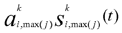

control module 4 and the resulting baseband signal is then sent to modulation/demodulation module 6. - Similarly during a downlink transmission,
control module 4 controls each transceiver Wi so that the baseband signal generated by modulation/demodulation module 6 is processed into
- When antenna 2 has not the specific scare-shape shown in
figure 3 , the weighting matrix applied to the transmitted/received signal is not necessarily a square matrix. Additionally, the weighting matrix takes into account the fact that the transmission/reception in a MIMO mode may also be done, as already mentioned, with two or three radiating elements REi ofarray 20. - With such geometrical aspect of antenna 2 and a disposal of radiating elements REi combined with such a
module control 4, it is possible to reduce the volume and cost of abase station 1 which is able to exchange traffic data signals in either a beamforming mode or a MIMO mode, since same antenna 2 is used to transmit/receive signals in the two different modes. -
Figure 4 represents the different steps of a method for transmitting/receiving data traffic signal in accordance with a specific embodiment of the invention. Before performing the control of the radiating elements to obtain a signal corresponding either to a transmission/reception in a MIMO mode or in a beamforming mode, the transmission/reception system ofbase station 1 needs to determine (step S1 onfigure 4 ) the most adequate mode to use to communicate with terminals T1, T2. For complementary reasons previously cited, it is interesting that the distribution of the terminals T1, T2 be performed considering the multipath degree in which is located the terminal T1, T2. Therefore, the transmission/reception system comprises determination means 5 for determining if said wireless terminal is located in a rich multipath environment or in a poor multipath environment. - In an urban area, sub-area 12 may typically represent an area where the terminals are located near the transmission/reception antenna, situation which increases the angular diversity. On the other hand sub-area 11 may correspond to a remote area, typically a border cell of a cellular communication network, for which, given to the distance between terminal T1 and
base station 1, angular diversity is low. Since the rich/poor multipath environment notion is then often linked to the notion of proximity/distance between terminals T1, T2 andbase station 1, an interesting way to sort terminals T1, T2 in two groups, is to use a distance criteria in calculating the distance between each terminal T1, T2 andbase station 1. A commonly located process can be used to determine both the position angle and the distance of the terminal from the antenna of the base station. In order to allow an operator to adapt eachbase station 1 with the specific urban characteristics, the distance sorting criteria is configurable and can be set in advance by the operator. Thus, if the calculated distance between terminal T1, T2 andbase station 1 is less than a predetermined threshold value,control module 4 will control antenna 2 to perform a data traffic exchange in a MIMO mode and if the calculated distance between terminal T1, T2 and thebase station 1 is greater than said threshold value,control module 4 will control antenna 2 to perform a data traffic exchange in a beamforming mode. - An other possibility to determine the multipath degree in which terminals T1, T2 are located can be made by using the knowledge at the receiver of the channel matrix transfer M. A narrowband communication system with a number MT of transmit antennas and a number of NR receiving antennas can indeed be modelled by its MTxNR transfer matrix M where an element m(i,j) of this matrix represents the complex channel gain from the transmitting antenna j to the receiving antenna i. The elements m(i,j) are estimated at the receiver thanks to the known pilot symbols transmitted by the broadcast common channel for the downlink case and transmitted by a dedicated channel for the uplink case.
- The algebraic rank of this matrix represents the number of degree of freedom of the channel and is evaluated through a classical rank calculation such as the SVD (Singular Value Decomposition). According to this rank calculation, M has a singular value decomposition in the form M=UDV* where U and V are NRxNR and MTxMT unitary matrices and D is a diagonal matrix. Each element s(i,i) of matrix D is called singular value of matrix M and the number of non zero elements of matrix D represents the rank of the channel matrix M.
If the rank r of the channel matrix transfer M is greater than one,control module 4 will then control antenna 2 to perform a data traffic exchange in a MIMO mode. If the rank r of the channel matrix transfer M is inferior or equal to one,control module 4 will then control antenna 2 to perform a data traffic exchange in a beamforming mode. Using this evaluation process is even more interesting that the value of the rank of the matrix may also indicate the number of antennas to be used in the MIMO mode. Thus, for example, if the rank r of the channel matrix transfer M is equal to three, the number of radiating elements to be selected bycontrol module 4 for the MIMO transmission/reception mode will be three. - After having determined the type of environment in which terminals T1, T2 are located,
control module 4 of the transmission/reception system controls radiating elements REi in order antenna 2 ofbase station 1 can perform a data traffic exchange with the corresponding transmission mode (steps S2 or S5 onfigure 4 ). - However, in case it is determined that a terminal considered to be in a multipath rich environment is not able, for any reason (it does not support MIMO technology, one of its antenna does not work anymore...) to exchange data traffic signal in a MIMO mode with
base station 1, the result of the determination of the multipath type environment is advantageously not tacking in account and each radiating element REi is controlled by an adaptive amplitude-phase law. - Furthermore, given the mobility of terminals T1, T2, it is necessary to regularly make the determination of the environment type at periodic times.
- Additionally to reduce the chance of having determined a wrong environment, a procedure for monitoring quality of communication can be added (step S4 on
figure 4 ). If the quality of communication is sharply deteriorated and becomes insufficient with a transmission mode,control module 4 will automatically perform a switch to control receiving elements REi in the other transmission mode. This protection will be useful especially for the case in which antenna 2 is controlled in a MIMO mode. Indeed, as already mentioned an inappropriate transition in this transmission/reception mode can be very damaging to the quality of communication and may even cause the interruption of the communication.
said transmission/reception system further comprises determination means adapted to determine if said wireless terminal is located in a multipath rich environment or in a multipath poor environment; and
in that said transmission/reception control module is adapted to control said antenna:
Claims (13)
- Transmission/reception system for use in a base station (1) of a wireless communication network, comprising :- a transmission/reception antenna (2) including an array (20) of radiating elements (RE1, REn) for exchanging data traffic signals with at least one wireless terminal (T1, T2);- a transmission/reception control module (4) for controlling said transmission/reception antenna (2);characterised in that
said transmission/reception system further comprises determination means (5) adapted to determine if said wireless terminal (T1, T2) is located in a multipath rich environment or in a multipath poor environment; and
in that said transmission/reception control module (4) is adapted to control said antenna (2):- either in a first beamforming mode in which each of said radiating elements (RE1, REn) is controlled by an adaptive amplitude-phase law so that transmission/reception antenna (2) forms a beam in the direction of said terminal (T1, T2) when said terminal (T1, T2) is located in a multipath poor environment- or in a second MIMO mode in which only selected radiating elements (RE1, REn) forming a subset within said array (20) are identically controlled when terminal (T1, T2) is located in a multipath rich environment. - The transmission/reception system as claimed in claim 1, characterised in that said determination means (5) are adapted to determine if said wireless terminal is located in a multipath rich environment or in a multipath poor environment by performing an estimation of a distance between said terminal (T1, T2) and said base station (1).
- The transmission/reception system as claimed in claim 2, characterised in that said determination means (5) determines that the said terminal (T1, T2) is located:- in a multipath poor environment when the said estimated distance is greater than a threshold value or;- in a multipath rich environment when the said estimated distance is lower or equal to a threshold value.
- The transmission/reception system as claimed in claim 1, characterised in that said determination means (5) are adapted to determine if said wireless terminal is located in a multipath rich environment or in a multipath poor environment by determining the rank of a channel matrix transfer.
- The transmission/reception system as claimed in claim 4, characterised in that said determination means (5) are adapted to determine that the said terminal (T1, T2) is located:- in a multipath poor environment when the rank r of said channel matrix transfer is lower or equal to one or;- in a multipath rich environment when the rank r of said channel matrix transfer is greater than one.
- The transmission/reception system as claimed in anyone of the preceding claims, characterised in that the radiating elements (RE1, REn) forming the subset are selected within said array (20) among the most spaced radiating elements (RE1, REn) of said array.
- The transmission/reception system as claimed in anyone of the preceding claims, characterised in that said radiating elements (RE1, REn) are arranged in a symmetrical array (20).
- The transmission/reception system as claimed in claim 7, characterised in that said antenna (2) is a square-shaped.
- The transmission/reception system as claimed in anyone of the preceding claims, characterised in that number of radiating elements (RE1, REn) is two, three or four.
- The transmission/reception system as claimed in claim 8, characterised in that the selected radiating elements (REi, REn) are located at the four corners of said square-shaped antenna (2).
- A Method for transmitting/receiving data traffic signals in a base station (1) of a wireless communication network, said base station (1) comprising a transmission/reception antenna (2) including an array (20) of radiating elements (RE1, REn) for exchanging data traffic signals with at least one wireless terminal (T1, T2) located in the coverage area of said antenna, characterised in that said method comprises:- a first step of determining (S1) if said wireless terminal is located in a multipath rich environment or in a multipath poor environment;- a second step of controlling said antenna (2)○ either in a first beamforming mode (S5), in which each of said radiating elements (RE1, REn) is controlled by an adaptive amplitude-phase law so that transmission/reception antenna (2) forms a beam in the direction of said terminal (T1, T2) when said terminal (T1, T2) is located in a multipath poor environment○ or in a second MIMO mode (S2), in which only selected radiating elements (RE1, REn) forming a subset within said array (20) are identically controlled when terminal (T1, T2) is located in a multipath rich environment.
- The method as claimed in claim 11, characterised in that prior to said first step of determining if said wireless terminal is located in a multipath rich environment or in a multipath poor environment, the method further comprises the step of:- determining if the said terminal (T1, T2) is able to function in a MIMO mode and;
in case of said terminal is not able to function in a MIMO mode:- not taking in account the result of the determination of the multipath type environment and;- controlling (S5) each said radiating element (RE1, REn) by an adaptive amplitude-phase law. - The method as claimed in claim 11, characterised in that, when said antenna 2 is controlled in said MIMO mode, the method further comprises the step of;- determining the quality of the data traffic transmission/reception signal (S4) between said antenna (2) and said terminal (T1, T2) and;- if the determined quality is insufficient, switching in the beamforming mode.
Priority Applications (1)
| Application Number | Priority Date | Filing Date | Title |
|---|---|---|---|
| EP08305014A EP2088689A1 (en) | 2008-02-05 | 2008-02-05 | Transmission/reception system and method for a base station of a wireless communication network |
Applications Claiming Priority (1)
| Application Number | Priority Date | Filing Date | Title |
|---|---|---|---|
| EP08305014A EP2088689A1 (en) | 2008-02-05 | 2008-02-05 | Transmission/reception system and method for a base station of a wireless communication network |
Publications (1)
| Publication Number | Publication Date |
|---|---|
| EP2088689A1 true EP2088689A1 (en) | 2009-08-12 |
Family
ID=39591867
Family Applications (1)
| Application Number | Title | Priority Date | Filing Date |
|---|---|---|---|
| EP08305014A Withdrawn EP2088689A1 (en) | 2008-02-05 | 2008-02-05 | Transmission/reception system and method for a base station of a wireless communication network |
Country Status (1)
| Country | Link |
|---|---|
| EP (1) | EP2088689A1 (en) |
Cited By (2)
| Publication number | Priority date | Publication date | Assignee | Title |
|---|---|---|---|---|
| GB2501809A (en) * | 2012-04-26 | 2013-11-06 | Korea Electronics Telecomm | Maritime wireless communication apparatus using vertically spaced antennas to provide frequency and space diversity gain |
| WO2021225674A1 (en) * | 2020-05-08 | 2021-11-11 | Qualcomm Incorporated | Switching between intra-band multiple input multiple output and inter-band carrier aggregation |
Citations (2)
| Publication number | Priority date | Publication date | Assignee | Title |
|---|---|---|---|---|
| EP1227539A1 (en) * | 2001-01-17 | 2002-07-31 | Lucent Technologies Inc. | Structure for multiple antenna configurations |
| EP1387501A1 (en) * | 2002-08-01 | 2004-02-04 | Sony International (Europe) GmbH | Transmitting and receiving device for a MIMO wireless communication system with adaptive antenna processing |
-
2008
- 2008-02-05 EP EP08305014A patent/EP2088689A1/en not_active Withdrawn
Patent Citations (2)
| Publication number | Priority date | Publication date | Assignee | Title |
|---|---|---|---|---|
| EP1227539A1 (en) * | 2001-01-17 | 2002-07-31 | Lucent Technologies Inc. | Structure for multiple antenna configurations |
| EP1387501A1 (en) * | 2002-08-01 | 2004-02-04 | Sony International (Europe) GmbH | Transmitting and receiving device for a MIMO wireless communication system with adaptive antenna processing |
Cited By (7)
| Publication number | Priority date | Publication date | Assignee | Title |
|---|---|---|---|---|
| GB2501809A (en) * | 2012-04-26 | 2013-11-06 | Korea Electronics Telecomm | Maritime wireless communication apparatus using vertically spaced antennas to provide frequency and space diversity gain |
| GB2501809B (en) * | 2012-04-26 | 2014-10-15 | Korea Electronics Telecomm | Maritime wireless communication apparatus and method |
| WO2021225674A1 (en) * | 2020-05-08 | 2021-11-11 | Qualcomm Incorporated | Switching between intra-band multiple input multiple output and inter-band carrier aggregation |
| US11522581B2 (en) | 2020-05-08 | 2022-12-06 | Qualcomm Incorporated | Switching between intra-band multiple input multiple output and inter-band carrier aggregation |
| CN115485984A (en) * | 2020-05-08 | 2022-12-16 | 高通股份有限公司 | Switching between in-band multiple-input multiple-output and inter-band carrier aggregation |
| EP4147370A1 (en) * | 2020-05-08 | 2023-03-15 | Qualcomm Incorporated | Switching between intra-band multiple input multiple output and inter-band carrier aggregation |
| CN115485984B (en) * | 2020-05-08 | 2024-11-15 | 高通股份有限公司 | Switching between intra-band MIMO and inter-band carrier aggregation |
Similar Documents
| Publication | Publication Date | Title |
|---|---|---|
| US7610036B2 (en) | Space-time-frequency sensing of RF spectrum in cognitive radios | |
| JP6600053B2 (en) | Communication method and apparatus using beamforming in wireless communication system | |
| EP2679058B1 (en) | Configuring power distribution within cooperation areas of cellular communication networks | |
| KR101910852B1 (en) | Method and apparatus for trnasmitting and receiving random access information in a wireless communication system | |
| US10050681B2 (en) | Apparatus and method for performing beamforming by using antenna array in wireless communication system | |
| EP2744120B1 (en) | Terminal in communication system and method for controlling same | |
| US9397731B2 (en) | Signaling support for antenna selection using subset lists and subset masks | |
| US7310537B2 (en) | Communication on multiple beams between stations | |
| EP2327172B1 (en) | Methods and arrangements in a radio access network | |
| US8145248B2 (en) | Apparatus and method for uplink beamforming and Space-Division Multiple Access (SDMA) in Multiple Input Multiple Output (MIMO) wireless communication systems | |
| US6917820B2 (en) | Method and apparatus for selection and use of optimal antennas in wireless systems | |
| US8009578B2 (en) | Wireless base station device, terminal, and wireless communication method | |
| EP3295584B1 (en) | Systems and methods of beam training for hybrid beamforming | |
| US20090296650A1 (en) | Coordinated linear beamforming in downlink multi-cell wireless networks | |
| US8144666B2 (en) | Downlink beamforming for broadband wireless networks | |
| US20140287791A1 (en) | Method and system for utilizing smart antennas in establishing a backhaul network | |
| EP3334057A1 (en) | Improved performance for a multiple antenna beamforming cellular network | |
| CN102098770A (en) | Method and apparatus for data communication in LTE cellular networks | |
| JP2004297750A (en) | Wireless communication system | |
| CN101622798A (en) | Switched beam antenna system and method with digitally controlled weighted radio frequency combining | |
| US20130203428A1 (en) | Interference alignment method and apparatus in wireless communication system | |
| US8615049B2 (en) | Method and apparatus for controlling co-channel interference in a wireless communication system | |
| US8452300B2 (en) | Communication system including a FEMTO base station and a communication terminal, and a communication method thereof | |
| EP2088689A1 (en) | Transmission/reception system and method for a base station of a wireless communication network | |
| Wang et al. | WiMAX system performance with multiple transmit and multiple receive antennas |
Legal Events
| Date | Code | Title | Description |
|---|---|---|---|
| PUAI | Public reference made under article 153(3) epc to a published international application that has entered the european phase |
Free format text: ORIGINAL CODE: 0009012 |
|
| AK | Designated contracting states |
Kind code of ref document: A1 Designated state(s): AT BE BG CH CY CZ DE DK EE ES FI FR GB GR HR HU IE IS IT LI LT LU LV MC MT NL NO PL PT RO SE SI SK TR |
|
| AX | Request for extension of the european patent |
Extension state: AL BA MK RS |
|
| AKX | Designation fees paid | ||
| REG | Reference to a national code |
Ref country code: DE Ref legal event code: 8566 |
|
| STAA | Information on the status of an ep patent application or granted ep patent |
Free format text: STATUS: THE APPLICATION IS DEEMED TO BE WITHDRAWN |
|
| 18D | Application deemed to be withdrawn |
Effective date: 20100213 |