EP2088479A1 - Image forming apparatus - Google Patents
Image forming apparatus Download PDFInfo
- Publication number
- EP2088479A1 EP2088479A1 EP09151490A EP09151490A EP2088479A1 EP 2088479 A1 EP2088479 A1 EP 2088479A1 EP 09151490 A EP09151490 A EP 09151490A EP 09151490 A EP09151490 A EP 09151490A EP 2088479 A1 EP2088479 A1 EP 2088479A1
- Authority
- EP
- European Patent Office
- Prior art keywords
- image forming
- forming apparatus
- sheet
- image
- control section
- Prior art date
- Legal status (The legal status is an assumption and is not a legal conclusion. Google has not performed a legal analysis and makes no representation as to the accuracy of the status listed.)
- Withdrawn
Links
- 238000012546 transfer Methods 0.000 claims abstract description 58
- 238000001816 cooling Methods 0.000 claims abstract description 16
- 238000004140 cleaning Methods 0.000 claims description 10
- 238000010438 heat treatment Methods 0.000 claims description 8
- 238000010586 diagram Methods 0.000 description 8
- 238000000034 method Methods 0.000 description 3
- 238000006243 chemical reaction Methods 0.000 description 2
- 238000004891 communication Methods 0.000 description 2
- 238000003384 imaging method Methods 0.000 description 2
- 238000012545 processing Methods 0.000 description 2
- 230000000630 rising effect Effects 0.000 description 2
- 238000003705 background correction Methods 0.000 description 1
- 239000003086 colorant Substances 0.000 description 1
- 230000006835 compression Effects 0.000 description 1
- 238000007906 compression Methods 0.000 description 1
- 238000013461 design Methods 0.000 description 1
- 230000006866 deterioration Effects 0.000 description 1
- 238000011161 development Methods 0.000 description 1
- 230000000694 effects Effects 0.000 description 1
- 230000020169 heat generation Effects 0.000 description 1
- 230000010365 information processing Effects 0.000 description 1
- 239000000463 material Substances 0.000 description 1
- 238000012856 packing Methods 0.000 description 1
- 230000000644 propagated effect Effects 0.000 description 1
- 238000012549 training Methods 0.000 description 1
- 238000009423 ventilation Methods 0.000 description 1
- 238000010792 warming Methods 0.000 description 1
- 239000002699 waste material Substances 0.000 description 1
Images

Classifications
-
- G—PHYSICS
- G03—PHOTOGRAPHY; CINEMATOGRAPHY; ANALOGOUS TECHNIQUES USING WAVES OTHER THAN OPTICAL WAVES; ELECTROGRAPHY; HOLOGRAPHY
- G03G—ELECTROGRAPHY; ELECTROPHOTOGRAPHY; MAGNETOGRAPHY
- G03G15/00—Apparatus for electrographic processes using a charge pattern
- G03G15/20—Apparatus for electrographic processes using a charge pattern for fixing, e.g. by using heat
- G03G15/2003—Apparatus for electrographic processes using a charge pattern for fixing, e.g. by using heat using heat
- G03G15/2014—Apparatus for electrographic processes using a charge pattern for fixing, e.g. by using heat using heat using contact heat
- G03G15/2017—Structural details of the fixing unit in general, e.g. cooling means, heat shielding means
-
- G—PHYSICS
- G03—PHOTOGRAPHY; CINEMATOGRAPHY; ANALOGOUS TECHNIQUES USING WAVES OTHER THAN OPTICAL WAVES; ELECTROGRAPHY; HOLOGRAPHY
- G03G—ELECTROGRAPHY; ELECTROPHOTOGRAPHY; MAGNETOGRAPHY
- G03G15/00—Apparatus for electrographic processes using a charge pattern
- G03G15/20—Apparatus for electrographic processes using a charge pattern for fixing, e.g. by using heat
- G03G15/2003—Apparatus for electrographic processes using a charge pattern for fixing, e.g. by using heat using heat
- G03G15/2014—Apparatus for electrographic processes using a charge pattern for fixing, e.g. by using heat using heat using contact heat
- G03G15/2039—Apparatus for electrographic processes using a charge pattern for fixing, e.g. by using heat using heat using contact heat with means for controlling the fixing temperature
-
- G—PHYSICS
- G03—PHOTOGRAPHY; CINEMATOGRAPHY; ANALOGOUS TECHNIQUES USING WAVES OTHER THAN OPTICAL WAVES; ELECTROGRAPHY; HOLOGRAPHY
- G03G—ELECTROGRAPHY; ELECTROPHOTOGRAPHY; MAGNETOGRAPHY
- G03G21/00—Arrangements not provided for by groups G03G13/00 - G03G19/00, e.g. cleaning, elimination of residual charge
- G03G21/20—Humidity or temperature control also ozone evacuation; Internal apparatus environment control
-
- G—PHYSICS
- G03—PHOTOGRAPHY; CINEMATOGRAPHY; ANALOGOUS TECHNIQUES USING WAVES OTHER THAN OPTICAL WAVES; ELECTROGRAPHY; HOLOGRAPHY
- G03G—ELECTROGRAPHY; ELECTROPHOTOGRAPHY; MAGNETOGRAPHY
- G03G2215/00—Apparatus for electrophotographic processes
- G03G2215/20—Details of the fixing device or porcess
- G03G2215/2003—Structural features of the fixing device
- G03G2215/2016—Heating belt
- G03G2215/2025—Heating belt the fixing nip having a rotating belt support member opposing a pressure member
- G03G2215/2032—Heating belt the fixing nip having a rotating belt support member opposing a pressure member the belt further entrained around additional rotating belt support members
-
- G—PHYSICS
- G03—PHOTOGRAPHY; CINEMATOGRAPHY; ANALOGOUS TECHNIQUES USING WAVES OTHER THAN OPTICAL WAVES; ELECTROGRAPHY; HOLOGRAPHY
- G03G—ELECTROGRAPHY; ELECTROPHOTOGRAPHY; MAGNETOGRAPHY
- G03G2221/00—Processes not provided for by group G03G2215/00, e.g. cleaning or residual charge elimination
- G03G2221/16—Mechanical means for facilitating the maintenance of the apparatus, e.g. modular arrangements and complete machine concepts
- G03G2221/1645—Mechanical means for facilitating the maintenance of the apparatus, e.g. modular arrangements and complete machine concepts for conducting air through the machine, e.g. cooling
Definitions
- the present invention relates to an image forming apparatus such as a copying machine, a printer, and a facsimile machine using electrophotographic method.
- image forming apparatuses such as copying machines, printers, and facsimile machines using electrophotographic method are used in various fields.
- Most of the above image forming apparatuses are provided with fixing units to melt and fix a toner image onto a sheet by heat.
- Such fixing units carries out a fixing process through a nip section configured with rollers or belts arranged to face one another by heat while conveying the sheet carrying the toner image thereon.
- a countermeasure to prevent the fixing unit having a heating section and a vicinity thereof from heating are needed, since the heating unit is subject to high temperature.
- the above problem is a serious problem for a high speed image forming apparatus used for a consecutive long-haul image forming job.
- the transfer unit used for a high speed image forming apparatus is often provided with a transfer cleaning section to remove toner adhered on the transfer roller or the transfer belt.
- Patent Document Unexamined Japanese Patent Application Publication No. H7-181874
- an object of the present invention is to realize the cooling device to effectively suppress raise in temperature of the transfer unit of the image forming apparatus and excessive raise in temperature of the fixing unit without the cost being raised.
- An image forming apparatus having: an image carrier to carry a toner image; a transfer unit to transfer the toner image on the image carrier onto a sheet through a rotating member disposed to face the image carrier; a fixing unit to heat and fix the transferred toner image onto the sheet; and a cooling device to suction air from a transfer unit side and discharge the air to a fixing unit side.
- Fig. 1 is a schematic diagram of a typical image forming apparatus G to produce a color copy.
- the image forming apparatus G shown in the figure is so-called a tandem type color image forming apparatus to form a full color image wherein a plurality of photoconductive members 31Y, 31M, 31C and 31K are arranged longitudinally in an array facing one intermediate transfer belt 41.
- the image forming apparatus G is provided with an automatic document feeding apparatus ADF at an upper part thereof.
- a document D placed on a document table 101 of the automatic document feeding apparatus ADF is separated piece by piece and sent to a document conveyance path and conveyed through a conveyance drum 102.
- An image on the document D is read while conveying through a document reading section 1 at a document image reading position RP.
- the document D having been read is ejected to a document ejection table 107 through a first conveyance guide 106 and document ejection rollers 105.
- Image forming apparatus G is configured with document reading section 1, exposing sections 2Y, 2M, 2C and 2K, image forming sections 3Y, 3M, 3C and 3K, an intermediate transfer section 4, a fixing unit 90, a reversal sheet ejection section 6, a sheet re-feeding section 7, a sheet feeding section 8, and a control section C, which are stored in a housing.
- the image of the document is irradiated through a lamp L at the document reading position RP and the reflected light is lead through a first mirror unit 11, a second mirror unit 12 and a lens 13 so that an image is formed on a light receiving surface of an imaging element CCD.
- the image signal converted through photoelectric conversion by the imaging element CCD is subject to processing such as A/D conversion, shading correction and compression in the image reading control section 14 and stored in a memory of the control section C as image data.
- image data stored in the memory of the control section C is subject to image processing with conditions set by a user so as to create output image data.
- Each of exposing sections 2Y, 2M, 2C and 2K is configured with a laser light source, a polygonal mirror, and a plurality of lenses to form a laser beam.
- the exposing sections 2Y, 2M, 2C and 2K carry out exposure scanning on surfaces of the photoconductive members 31Y, 31M, 31C and 31K representing components of the image forming sections 3Y, 3M, 3C and 2K with the laser beam in accordance with output information outputted based on the output image data sent from the control section C.
- the image forming section 3Y is configured with a photoconductive member 31Y, and a main charging section 32Y, a developing section 33Y, a first transfer roller 34Y and a cleaning section 35Y disposed at a vicinity thereof.
- the image forming sections of respective colors are provided with toner supply sections to supply toner from toner bottles TY, TM, TC and TK to the developing sections 33Y, 33M, 33C and 33K.
- the latent images formed on the photoconductive members 31Y, 31M, 31C and 31K through exposure scanning of the laser beam are developed through the corresponding developing sections 33Y, 33M, 33C and 33K, thus toner images are formed on respective photoconductive members.
- the intermediate transfer section 4 is configured with an intermediate transfer belt 41, first transfer rollers 34Y, 34M, 34C and 34K, a transfer unit 50 and a belt cleaning section 43.
- the toner images formed on the photoconductive members 31Y, 31M, 31C and 31K are subsequently transferred on a predetermined position on the intermediate transfer belt 41 representing an image carrier, usually called an intermediate transfer member, through the first rollers 34Y, 34M, 34C and 34K of the intermediate transfer section 4.
- the cleaning sections 35Y, 35M, 35C and 35K remove the residual toner from the surfaces of the photoconductive members.
- the toner image transferred onto the intermediate transfer belt 41 is transferred through a transfer unit 50 onto a sheet P representing a transfer material fed from a sheet feeding section 8 through sheet feeding roller 81 which conducts sheet feeding timing.
- the surface of the intermediate transfer belt 41 is cleaned through the belt cleaning section 43 and served for subsequent image transfer.
- the transferred sheet P carrying the toner image thereon is sent to the fixing unit 90, thus the toner image is fixed onto the sheet P through pressure heating.
- the sheet P having been fixed through the fixed unit 90 is conveyed through an ejection sheet reversal section 6 and ejected to an ejection sheet table 61.
- the ejection sheet guide 62 leads the sheet P downwards once, then after a rear of the sheet P is grasped by ejection sheet reversal roller 63, the sheet P is reversed, and an ejection sheet guide 62 leads the sheet P to ejection sheet roller 64 to eject the sheet.
- the ejection sheet guide 62 leads the sheet P to the sheet re-feeding section 7 on the lower side. Then a sheet re-feeding reversal roller 71 grasps the rear end of the sheet P, thereafter the sheet is reversed by reverse sending and sent out to a sheet re-feeding conveyance path 72 to be served for image forming on the reverse surface.
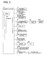
- Fig. 2 is a block diagram showing control of the image forming apparatus G.
- the control section C is a computer system having a CPU, a memory, a calculation unit, an I/O port, a communication interface and a driving circuit.
- the control section C carries out control by executing a predetermined program stored in a memory M.
- control section C exchanges information between a plurality of information processing devices via the communication device TR.
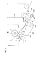
- Fig. 3 is a schematic diagram to describe a cooling device 200.
- the sheet P sent from the sheet feeding rollers 81 enters from a direction of an arrow a shown by dashed lines and the transfer unit 50 transfers a toner image on the intermediate transfer belt 41 representing an image carrier onto the sheet P, then the fixing unit 90 fixes the toner image, thereafter the sheet P is sent in a direction of an arrow b.
- the transfer unit 50 is configured with rollers 51, 52 and 53, a belt 54 representing a rotating member, and a cleaning device 500.
- the belt 54 is trained about the rollers 51, 52 and 53, and disposed to face the intermediate transfer belt 41 representing an image carrier.
- the cleaning device 500 is provided with a rotation brush 501 and a blade 502 to remove extraneous matters such as toner adhering on a circumferential surface of the belt.
- Fixing unit 90 is a publicly known fixing device configured with a heating roller 91, rollers 92, 93 94 and 95, an urging member 95, and a fixing belt 96 training about a plurality of the rollers thereof and the urging member 95.
- a cooling device 200 is configured with a plurality of funs 201 arrayed in a depth direction in the figure, namely in a direction perpendicular to the traveling direction of the sheet P and controlled by the control section C in rotation speed thereof, and a duct 202 to lead air sent from the fans 201 to a specific direction.
- the cooling device 200 disposed between the transfer unit 50 and the fixing unit 90, suctions air at a vicinity of the transfer unit 50 and sends below the fixing unit 90 as a broken arrows c and d show.
- the transfer unit 50 is prevented from temperature increase through air flow at vicinities of the transfer unit 50 and in particular vicinities of cleaning unit 500, generated by suction of the cooling device 90.
- the air having cooled the transfer unit 50 is led through the duct 202 and discharged, then flows on the surface of the fixing belt 96 which is in a high temperature.
- Such air flow prevents the fixing belt 96 from excessive temperature increase and suppresses temperature increase of the transfer unit 50, since air flow of the air heated by heat generation of the fixing unit 90 towards the transfer unit 50 is prevented.
- the cooling device 200 sends air in a way that the air flows on the circumferential surface of the belt located at an opposite side of a nip section N configured with the heating roller 91 of the fixing unit 90 and a fixing belt 96, therefore the air flow cannot be a factor to bother travel of the sheet P towards the nip section N.
- the plurality of the fans 201 are controlled by the control section C in rotation speed.
- the rotation speed and on/off timing are controlled.
- the fan 201 is stopped or the rotation speed thereof is reduced during warming up of the apparatus or when the operation has been stopped for a certain period of time.
- the above control is determined at the design phase.
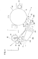
- Fig. 4 is a diagram describing an exemplary application for a common monochrome image forming apparatus.
- Fig. 4 shows a portion of image forming apparatus where a laser beam LB forms a latent image on the photoconductive drum 31, a developing section 33 carries out toner developing, and a transfer unit 50 transfers the toner image on the photoconductive drum 31 representing an image carrier onto a sheet traveling in a direction of an arrow a.
- the cooling device 200 of the present invention can be applied to an image carrier disposed to face the transfer unit 50 irrespective of whether the image carrier represents a photoconductive member or an intermediate transfer member.
- the present invention can be applied to the image carrier irrespective of whether the image carrier is a drum or a belt.
Landscapes
- Physics & Mathematics (AREA)
- General Physics & Mathematics (AREA)
- Life Sciences & Earth Sciences (AREA)
- Engineering & Computer Science (AREA)
- Atmospheric Sciences (AREA)
- Biodiversity & Conservation Biology (AREA)
- Ecology (AREA)
- Environmental & Geological Engineering (AREA)
- Environmental Sciences (AREA)
- Electrostatic Charge, Transfer And Separation In Electrography (AREA)
- Fixing For Electrophotography (AREA)
- Control Or Security For Electrophotography (AREA)
Abstract
Description
- This application is based on Japanese Patent Application No.
2008-028569 filed on February 08, 2008 - The present invention relates to an image forming apparatus such as a copying machine, a printer, and a facsimile machine using electrophotographic method.
- In recent years, image forming apparatuses such as copying machines, printers, and facsimile machines using electrophotographic method are used in various fields.
- Most of the above image forming apparatuses are provided with fixing units to melt and fix a toner image onto a sheet by heat.
- Such fixing units carries out a fixing process through a nip section configured with rollers or belts arranged to face one another by heat while conveying the sheet carrying the toner image thereon.
- A countermeasure to prevent the fixing unit having a heating section and a vicinity thereof from heating are needed, since the heating unit is subject to high temperature.
- As the countermeasures to prevent the fixing unit from heating, for example, there is suggested to provide a ventilation flue to supply cool air and to control the air by turning on and off a fan (for example refer to Patent document 1: Unexamined Japanese Patent Application Publication No.
H7-181874 - However, it is difficult to completely prevent air inside the image forming apparatus from rising in temperature due to heat generated by the fixing unit or to prevent each device related to image forming provided in the apparatus from rising in temperature.
- The above problem is a serious problem for a high speed image forming apparatus used for a consecutive long-haul image forming job.
- There is publicly known a high speed image forming apparatus having a transfer unit to transfer a toner image, formed on an image carrier such as a photoconductive member or intermediate transfer member, onto the sheet through a transfer roller or a transfer belt disposed to face the image carrier.
- When temperature of the transfer unit is raised by the heat propagated from the fixing unit, temperature of the image carrier in direct contact with the transfer unit raises immediately and eventually, temperature of developer and a development device is raised which results in deterioration of image quality.
- Also, the transfer unit used for a high speed image forming apparatus is often provided with a transfer cleaning section to remove toner adhered on the transfer roller or the transfer belt.
- When the temperature of the transfer cleaning section raises, packing of waste toner occurs.
- To prevent occurrence of the above problems, a cooling device becomes necessary to suppress raise in temperature of the transfer units, however such countermeasure tends to increase cost.
- Patent Document: Unexamined Japanese Patent Application Publication No.
H7-181874 - In view of the above problems, an object of the present invention is to realize the cooling device to effectively suppress raise in temperature of the transfer unit of the image forming apparatus and excessive raise in temperature of the fixing unit without the cost being raised.
- The above problem can be solved by the following. An image forming apparatus, having: an image carrier to carry a toner image; a transfer unit to transfer the toner image on the image carrier onto a sheet through a rotating member disposed to face the image carrier; a fixing unit to heat and fix the transferred toner image onto the sheet; and a cooling device to suction air from a transfer unit side and discharge the air to a fixing unit side.
-
-
Fig. 1 is a schematic diagram of an image forming apparatus. -
Fig. 2 is a block diagram showing control of the image forming apparatus. -
Fig. 3 is a schematic diagram describing a cooling device. -
Fig. 4 is a diagram describing an exemplary application for a common monochrome image forming apparatus. - An embodiment of the present invention will be described with reference to the drawings.
-
Fig. 1 is a schematic diagram of a typical image forming apparatus G to produce a color copy. - The image forming apparatus G shown in the figure is so-called a tandem type color image forming apparatus to form a full color image wherein a plurality of
photoconductive members intermediate transfer belt 41. - The image forming apparatus G is provided with an automatic document feeding apparatus ADF at an upper part thereof.
- A document D placed on a document table 101 of the automatic document feeding apparatus ADF is separated piece by piece and sent to a document conveyance path and conveyed through a
conveyance drum 102. - An image on the document D is read while conveying through a
document reading section 1 at a document image reading position RP. The document D having been read is ejected to a document ejection table 107 through afirst conveyance guide 106 anddocument ejection rollers 105. - Image forming apparatus G is configured with
document reading section 1, exposingsections image forming sections intermediate transfer section 4, afixing unit 90, a reversalsheet ejection section 6, asheet re-feeding section 7, asheet feeding section 8, and a control section C, which are stored in a housing. - In the
document reading section 1, the image of the document is irradiated through a lamp L at the document reading position RP and the reflected light is lead through afirst mirror unit 11, asecond mirror unit 12 and alens 13 so that an image is formed on a light receiving surface of an imaging element CCD. - The image signal converted through photoelectric conversion by the imaging element CCD is subject to processing such as A/D conversion, shading correction and compression in the image
reading control section 14 and stored in a memory of the control section C as image data. - In the image data stored in the memory of the control section C is subject to image processing with conditions set by a user so as to create output image data.
- Each of exposing
sections - The
exposing sections photoconductive members image forming sections - On the
photoconductive members - The
image forming section 3Y is configured with aphotoconductive member 31Y, and a main charging section 32Y, a developingsection 33Y, afirst transfer roller 34Y and acleaning section 35Y disposed at a vicinity thereof. - Also, the image forming sections of respective colors are provided with toner supply sections to supply toner from toner bottles TY, TM, TC and TK to the developing
sections - The latent images formed on the
photoconductive members sections - The
intermediate transfer section 4 is configured with anintermediate transfer belt 41,first transfer rollers transfer unit 50 and abelt cleaning section 43. - The toner images formed on the
photoconductive members intermediate transfer belt 41 representing an image carrier, usually called an intermediate transfer member, through thefirst rollers intermediate transfer section 4. - Meanwhile, after transferring the toner image, the
cleaning sections 35Y, 35M, 35C and 35K remove the residual toner from the surfaces of the photoconductive members. - On other hand, the toner image transferred onto the
intermediate transfer belt 41 is transferred through atransfer unit 50 onto a sheet P representing a transfer material fed from asheet feeding section 8 throughsheet feeding roller 81 which conducts sheet feeding timing. - After transferring the toner image onto the sheet P, the surface of the
intermediate transfer belt 41 is cleaned through thebelt cleaning section 43 and served for subsequent image transfer. - On the other hand, the transferred sheet P carrying the toner image thereon is sent to the
fixing unit 90, thus the toner image is fixed onto the sheet P through pressure heating. - The sheet P having been fixed through the
fixed unit 90 is conveyed through an ejection sheetreversal section 6 and ejected to an ejection sheet table 61. In case the sheet P is reversed to be ejected, theejection sheet guide 62 leads the sheet P downwards once, then after a rear of the sheet P is grasped by ejectionsheet reversal roller 63, the sheet P is reversed, and anejection sheet guide 62 leads the sheet P toejection sheet roller 64 to eject the sheet. - Meanwhile, in case the image is formed on the reverse side of the sheet P as well, after image fixing on the obverse side of the sheet P is completed, the
ejection sheet guide 62 leads the sheet P to thesheet re-feeding section 7 on the lower side. Then a sheet re-feedingreversal roller 71 grasps the rear end of the sheet P, thereafter the sheet is reversed by reverse sending and sent out to a sheetre-feeding conveyance path 72 to be served for image forming on the reverse surface. -
Fig. 2 is a block diagram showing control of the image forming apparatus G. - The control section C is a computer system having a CPU, a memory, a calculation unit, an I/O port, a communication interface and a driving circuit.
- The control section C carries out control by executing a predetermined program stored in a memory M.
- Also the control section C exchanges information between a plurality of information processing devices via the communication device TR.
- Meanwhile, in the present figure, portions not related to the description of the present invention are omitted.
-
Fig. 3 is a schematic diagram to describe acooling device 200. - The sheet P sent from the
sheet feeding rollers 81 enters from a direction of an arrow a shown by dashed lines and thetransfer unit 50 transfers a toner image on theintermediate transfer belt 41 representing an image carrier onto the sheet P, then thefixing unit 90 fixes the toner image, thereafter the sheet P is sent in a direction of an arrow b. - The
transfer unit 50 is configured withrollers belt 54 representing a rotating member, and acleaning device 500. Thebelt 54 is trained about therollers intermediate transfer belt 41 representing an image carrier. - The
cleaning device 500 is provided with arotation brush 501 and ablade 502 to remove extraneous matters such as toner adhering on a circumferential surface of the belt. - Fixing
unit 90 is a publicly known fixing device configured with aheating roller 91,rollers member 95, and a fixingbelt 96 training about a plurality of the rollers thereof and the urgingmember 95. - A
cooling device 200 is configured with a plurality offuns 201 arrayed in a depth direction in the figure, namely in a direction perpendicular to the traveling direction of the sheet P and controlled by the control section C in rotation speed thereof, and aduct 202 to lead air sent from thefans 201 to a specific direction. - As
Fig. 3 shows, thecooling device 200, disposed between thetransfer unit 50 and the fixingunit 90, suctions air at a vicinity of thetransfer unit 50 and sends below the fixingunit 90 as a broken arrows c and d show. - The
transfer unit 50 is prevented from temperature increase through air flow at vicinities of thetransfer unit 50 and in particular vicinities ofcleaning unit 500, generated by suction of thecooling device 90. - The air having cooled the
transfer unit 50 is led through theduct 202 and discharged, then flows on the surface of the fixingbelt 96 which is in a high temperature. - Such air flow prevents the fixing
belt 96 from excessive temperature increase and suppresses temperature increase of thetransfer unit 50, since air flow of the air heated by heat generation of the fixingunit 90 towards thetransfer unit 50 is prevented. - Meanwhile, the
cooling device 200 sends air in a way that the air flows on the circumferential surface of the belt located at an opposite side of a nip section N configured with theheating roller 91 of the fixingunit 90 and a fixingbelt 96, therefore the air flow cannot be a factor to bother travel of the sheet P towards the nip section N. - As described in the forgoing, the plurality of the
fans 201 are controlled by the control section C in rotation speed. In accordance with operation conditions of the image forming apparatus G the rotation speed and on/off timing are controlled. - For example, the
fan 201 is stopped or the rotation speed thereof is reduced during warming up of the apparatus or when the operation has been stopped for a certain period of time. - The above control is determined at the design phase.
- As above, while the present invention has been described with reference to the color image forming apparatus having the
intermediate transfer belt 41 as the image carrier, the same effect as the present invention can be expected in image forming apparatuses not having theintermediate transfer belt 41. -
Fig. 4 is a diagram describing an exemplary application for a common monochrome image forming apparatus. -
Fig. 4 shows a portion of image forming apparatus where a laser beam LB forms a latent image on thephotoconductive drum 31, a developingsection 33 carries out toner developing, and atransfer unit 50 transfers the toner image on thephotoconductive drum 31 representing an image carrier onto a sheet traveling in a direction of an arrow a. - As above, the
cooling device 200 of the present invention can be applied to an image carrier disposed to face thetransfer unit 50 irrespective of whether the image carrier represents a photoconductive member or an intermediate transfer member. - Also, the present invention can be applied to the image carrier irrespective of whether the image carrier is a drum or a belt.
- As described in foregoing, by providing the cooling device of the present invention, temperature increase of the transfer unit and excessive temperature increase of the fixing unit can be suppressed without increasing cost.
Claims (11)
- An image forming apparatus, comprising:an image carrier to carry a toner image;a transfer unit to transfer the toner image on the image carrier onto a sheet through a rotating member disposed to face the image carrier;a fixing unit to heat and fix the transferred toner image onto the sheet; anda cooling device to suction air from a transfer unit side and discharge the air to a fixing unit side.
- The image forming apparatus of claim 1, further comprising a cleaning device to remove extraneous matters adhering on a circumferential surface of the rotating member.
- The image forming apparatus of claim 1, wherein the fixing unit, having a first member and a second member facing one another to rotate, conveys the sheet grasped by a nip section configured with the first member and the second member while heating the sheet, the first member is disposed at a contact side to the toner image transferred on the sheet being conveyed and the cooling device discharges air towards a circumferential surface disposed at an opposite side of the nip section of the second member.
- The image forming apparatus of claim 1, where the cooling device is provided with a plurality of fans arrayed in a straight line perpendicular to a conveyance direction of the sheet.
- The image forming apparatus of claim 1, further comprising a control section to control air volume of the cooling device.
- The image forming apparatus of claim 5, comprising a fan, wherein the control section controls rotation speed of the fan.
- The image forming apparatus of claim 6, wherein the control section stops the fan while the image forming apparatus is in warm-up operation.
- The image forming apparatus of claim 6, wherein the control section stops the fan when the image forming apparatus ceases operation for more than a certain period of time.
- The image forming apparatus of claim 6, wherein the control section reduces the rotation speed of the fan while the image forming apparatus is in warm-up operation.
- The image forming apparatus of claim 6, wherein the control section reduces the rotation speed of the fan when the image forming apparatus ceases operation for more than a certain period of time.
- The image forming apparatus of claim 1, wherein the rotation member is a transfer belt.
Applications Claiming Priority (1)
| Application Number | Priority Date | Filing Date | Title |
|---|---|---|---|
| JP2008028569A JP5151520B2 (en) | 2008-02-08 | 2008-02-08 | Image forming apparatus |
Publications (1)
| Publication Number | Publication Date |
|---|---|
| EP2088479A1 true EP2088479A1 (en) | 2009-08-12 |
Family
ID=40673967
Family Applications (1)
| Application Number | Title | Priority Date | Filing Date |
|---|---|---|---|
| EP09151490A Withdrawn EP2088479A1 (en) | 2008-02-08 | 2009-01-28 | Image forming apparatus |
Country Status (3)
| Country | Link |
|---|---|
| US (1) | US7953342B2 (en) |
| EP (1) | EP2088479A1 (en) |
| JP (1) | JP5151520B2 (en) |
Families Citing this family (4)
| Publication number | Priority date | Publication date | Assignee | Title |
|---|---|---|---|---|
| JP5445762B2 (en) * | 2009-12-14 | 2014-03-19 | 富士ゼロックス株式会社 | Image forming apparatus |
| JP2011221066A (en) * | 2010-04-05 | 2011-11-04 | Konica Minolta Business Technologies Inc | Image forming apparatus |
| JP5941026B2 (en) * | 2013-09-02 | 2016-06-29 | 株式会社沖データ | Image forming apparatus |
| JP6778414B2 (en) * | 2016-10-28 | 2020-11-04 | 株式会社リコー | Belt device, transfer device and image forming device |
Citations (7)
| Publication number | Priority date | Publication date | Assignee | Title |
|---|---|---|---|---|
| JPH04340577A (en) * | 1991-05-16 | 1992-11-26 | Ricoh Co Ltd | Copy machine fixing device |
| JPH07129065A (en) * | 1993-06-21 | 1995-05-19 | Ricoh Co Ltd | Electrophotographic imager |
| JPH07181874A (en) | 1993-12-22 | 1995-07-21 | Ricoh Co Ltd | Image forming device |
| US6253042B1 (en) * | 1998-12-19 | 2001-06-26 | Samsung Electronics Co., Ltd. | Method for controlling a fan of an electronic photo device |
| US20060051124A1 (en) * | 2004-09-08 | 2006-03-09 | Canon Kabushiki Kaisha | Image forming apparatus |
| US20060083539A1 (en) * | 2004-10-20 | 2006-04-20 | Canon Kabushiki Kaisha | Image forming apparatus |
| US20070110471A1 (en) * | 2005-11-16 | 2007-05-17 | Oki Data Corporation | Belt drive device and image forming apparatus having the same |
Family Cites Families (21)
| Publication number | Priority date | Publication date | Assignee | Title |
|---|---|---|---|---|
| US5307132A (en) * | 1987-11-12 | 1994-04-26 | Canon Kabushiki Kaisha | Image forming apparatus having a controller for discharging air in response to a heating condition of an image fixing device |
| JP2874907B2 (en) * | 1989-08-25 | 1999-03-24 | 株式会社東芝 | Image forming device |
| JPH0451179A (en) * | 1990-06-19 | 1992-02-19 | Canon Inc | image forming device |
| JPH06242701A (en) * | 1993-02-19 | 1994-09-02 | Fuji Xerox Co Ltd | Fixing device |
| JPH0710745U (en) * | 1993-07-23 | 1995-02-14 | 旭光学工業株式会社 | Internal blower structure of electrophotographic device |
| US5787321A (en) * | 1996-02-09 | 1998-07-28 | Asahi Kogaku Kogyo Kabushiki Kaisha | Temperature controlling device for fixing unit |
| JPH10307517A (en) * | 1997-05-07 | 1998-11-17 | Matsushita Electric Ind Co Ltd | Image forming device |
| JP2002258722A (en) * | 2000-12-28 | 2002-09-11 | Ricoh Co Ltd | Image forming apparatus, recording medium, and program |
| JP2002333815A (en) * | 2001-05-08 | 2002-11-22 | Canon Inc | Image forming device |
| US6865361B2 (en) * | 2001-11-12 | 2005-03-08 | Seiko Epson Corporation | Transfer belt unit and image forming apparatus using the same |
| JP4277248B2 (en) * | 2002-01-16 | 2009-06-10 | 富士ゼロックス株式会社 | Image forming apparatus |
| JP2004013022A (en) * | 2002-06-10 | 2004-01-15 | Canon Inc | Fixing device |
| JP2004109537A (en) * | 2002-09-19 | 2004-04-08 | Fuji Xerox Co Ltd | Image forming apparatus and driving setting method for fan used for image forming apparatus |
| JP2005017316A (en) * | 2003-06-23 | 2005-01-20 | Ricoh Co Ltd | Image forming apparatus and copying apparatus |
| JP2005049793A (en) * | 2003-07-31 | 2005-02-24 | Kyocera Mita Corp | Image forming apparatus |
| JP4551732B2 (en) * | 2004-10-20 | 2010-09-29 | キヤノン株式会社 | Fixing device |
| KR20070000595A (en) * | 2005-06-28 | 2007-01-03 | 삼성전자주식회사 | Fusing unit cooling fan control method and image forming apparatus using the same |
| JP4890821B2 (en) * | 2005-09-13 | 2012-03-07 | キヤノン株式会社 | Image forming apparatus |
| JP2007219192A (en) * | 2006-02-17 | 2007-08-30 | Seiko Epson Corp | Image forming apparatus and cooling control method therefor |
| JP2007328275A (en) * | 2006-06-09 | 2007-12-20 | Ricoh Co Ltd | Image forming apparatus |
| JP4867506B2 (en) * | 2006-07-05 | 2012-02-01 | 富士ゼロックス株式会社 | Blower system |
-
2008
- 2008-02-08 JP JP2008028569A patent/JP5151520B2/en not_active Expired - Fee Related
-
2009
- 2009-01-28 EP EP09151490A patent/EP2088479A1/en not_active Withdrawn
- 2009-02-03 US US12/364,639 patent/US7953342B2/en not_active Expired - Fee Related
Patent Citations (7)
| Publication number | Priority date | Publication date | Assignee | Title |
|---|---|---|---|---|
| JPH04340577A (en) * | 1991-05-16 | 1992-11-26 | Ricoh Co Ltd | Copy machine fixing device |
| JPH07129065A (en) * | 1993-06-21 | 1995-05-19 | Ricoh Co Ltd | Electrophotographic imager |
| JPH07181874A (en) | 1993-12-22 | 1995-07-21 | Ricoh Co Ltd | Image forming device |
| US6253042B1 (en) * | 1998-12-19 | 2001-06-26 | Samsung Electronics Co., Ltd. | Method for controlling a fan of an electronic photo device |
| US20060051124A1 (en) * | 2004-09-08 | 2006-03-09 | Canon Kabushiki Kaisha | Image forming apparatus |
| US20060083539A1 (en) * | 2004-10-20 | 2006-04-20 | Canon Kabushiki Kaisha | Image forming apparatus |
| US20070110471A1 (en) * | 2005-11-16 | 2007-05-17 | Oki Data Corporation | Belt drive device and image forming apparatus having the same |
Also Published As
| Publication number | Publication date |
|---|---|
| JP5151520B2 (en) | 2013-02-27 |
| US7953342B2 (en) | 2011-05-31 |
| JP2009186882A (en) | 2009-08-20 |
| US20090202267A1 (en) | 2009-08-13 |
Similar Documents
| Publication | Publication Date | Title |
|---|---|---|
| US8682205B2 (en) | Cooling device, cooling method, and image forming apparatus | |
| US8351814B2 (en) | Image forming apparatus with fan for blowing air to transfer sheet | |
| EP2088479A1 (en) | Image forming apparatus | |
| JP6350506B2 (en) | Image reading apparatus and image forming system | |
| US10620583B2 (en) | Image forming apparatus and method | |
| US7403732B2 (en) | Image forming apparatus equipped with LED printing head | |
| JP2012254841A (en) | Image forming apparatus | |
| JP2008185896A (en) | Image forming apparatus | |
| JP5817375B2 (en) | Image forming apparatus | |
| EP2388658A2 (en) | Fixing device and image forming apparatus | |
| JP6107393B2 (en) | Image forming apparatus | |
| JP5813605B2 (en) | Image forming apparatus and image forming system | |
| CN102621868A (en) | Image forming apparatus | |
| JP2009276370A (en) | Image forming apparatus | |
| US20250328104A1 (en) | Image forming apparatus | |
| JP2009175495A (en) | Image forming system | |
| JP2006343607A (en) | Image forming apparatus | |
| JP2010063003A (en) | Image reading apparatus and image forming apparatus | |
| JP2002072832A (en) | Image forming device | |
| JP6394550B2 (en) | Image forming apparatus | |
| JPH07181874A (en) | Image forming device | |
| JP2003029540A (en) | Color image forming equipment | |
| JP2009300519A (en) | Image forming apparatus | |
| JP2004157369A (en) | Image forming apparatus | |
| JP2006176307A (en) | Image forming device |
Legal Events
| Date | Code | Title | Description |
|---|---|---|---|
| PUAI | Public reference made under article 153(3) epc to a published international application that has entered the european phase |
Free format text: ORIGINAL CODE: 0009012 |
|
| AK | Designated contracting states |
Kind code of ref document: A1 Designated state(s): AT BE BG CH CY CZ DE DK EE ES FI FR GB GR HR HU IE IS IT LI LT LU LV MC MK MT NL NO PL PT RO SE SI SK TR |
|
| AX | Request for extension of the european patent |
Extension state: AL BA RS |
|
| 17P | Request for examination filed |
Effective date: 20100113 |
|
| 17Q | First examination report despatched |
Effective date: 20100209 |
|
| AKX | Designation fees paid |
Designated state(s): DE FR GB |
|
| STAA | Information on the status of an ep patent application or granted ep patent |
Free format text: STATUS: THE APPLICATION IS DEEMED TO BE WITHDRAWN |
|
| 18D | Application deemed to be withdrawn |
Effective date: 20180801 |