EP2088436A1 - Cartridge and analysis system - Google Patents
Cartridge and analysis system Download PDFInfo
- Publication number
- EP2088436A1 EP2088436A1 EP07831254A EP07831254A EP2088436A1 EP 2088436 A1 EP2088436 A1 EP 2088436A1 EP 07831254 A EP07831254 A EP 07831254A EP 07831254 A EP07831254 A EP 07831254A EP 2088436 A1 EP2088436 A1 EP 2088436A1
- Authority
- EP
- European Patent Office
- Prior art keywords
- analyzing
- cartridge
- biosensor
- tool
- analyzer
- Prior art date
- Legal status (The legal status is an assumption and is not a legal conclusion. Google has not performed a legal analysis and makes no representation as to the accuracy of the status listed.)
- Granted
Links
- 238000004458 analytical method Methods 0.000 title description 2
- 238000003825 pressing Methods 0.000 claims description 9
- 238000006073 displacement reaction Methods 0.000 claims description 3
- 239000000463 material Substances 0.000 description 27
- 238000001514 detection method Methods 0.000 description 10
- 239000008280 blood Substances 0.000 description 7
- 210000004369 blood Anatomy 0.000 description 7
- 238000003780 insertion Methods 0.000 description 7
- 230000037431 insertion Effects 0.000 description 7
- 239000011347 resin Substances 0.000 description 7
- 229920005989 resin Polymers 0.000 description 7
- 239000003153 chemical reaction reagent Substances 0.000 description 6
- 230000004044 response Effects 0.000 description 6
- 238000004519 manufacturing process Methods 0.000 description 5
- 239000004020 conductor Substances 0.000 description 3
- 230000007246 mechanism Effects 0.000 description 3
- 238000000465 moulding Methods 0.000 description 3
- WQZGKKKJIJFFOK-GASJEMHNSA-N Glucose Natural products OC[C@H]1OC(O)[C@H](O)[C@@H](O)[C@@H]1O WQZGKKKJIJFFOK-GASJEMHNSA-N 0.000 description 2
- 108090000854 Oxidoreductases Proteins 0.000 description 2
- 102000004316 Oxidoreductases Human genes 0.000 description 2
- HVYWMOMLDIMFJA-DPAQBDIFSA-N cholesterol Chemical compound C1C=C2C[C@@H](O)CC[C@]2(C)[C@@H]2[C@@H]1[C@@H]1CC[C@H]([C@H](C)CCCC(C)C)[C@@]1(C)CC2 HVYWMOMLDIMFJA-DPAQBDIFSA-N 0.000 description 2
- 230000008878 coupling Effects 0.000 description 2
- 238000010168 coupling process Methods 0.000 description 2
- 238000005859 coupling reaction Methods 0.000 description 2
- 239000008103 glucose Substances 0.000 description 2
- 238000005304 joining Methods 0.000 description 2
- JVTAAEKCZFNVCJ-UHFFFAOYSA-N lactic acid Chemical compound CC(O)C(O)=O JVTAAEKCZFNVCJ-UHFFFAOYSA-N 0.000 description 2
- 239000007788 liquid Substances 0.000 description 2
- 239000000155 melt Substances 0.000 description 2
- BASFCYQUMIYNBI-UHFFFAOYSA-N platinum Chemical compound [Pt] BASFCYQUMIYNBI-UHFFFAOYSA-N 0.000 description 2
- 230000027756 respiratory electron transport chain Effects 0.000 description 2
- 239000000126 substance Substances 0.000 description 2
- 210000002700 urine Anatomy 0.000 description 2
- OKTJSMMVPCPJKN-UHFFFAOYSA-N Carbon Chemical compound [C] OKTJSMMVPCPJKN-UHFFFAOYSA-N 0.000 description 1
- 108010050375 Glucose 1-Dehydrogenase Proteins 0.000 description 1
- 108010015776 Glucose oxidase Proteins 0.000 description 1
- 239000004366 Glucose oxidase Substances 0.000 description 1
- BQCADISMDOOEFD-UHFFFAOYSA-N Silver Chemical compound [Ag] BQCADISMDOOEFD-UHFFFAOYSA-N 0.000 description 1
- 239000000853 adhesive Substances 0.000 description 1
- 230000001070 adhesive effect Effects 0.000 description 1
- WQZGKKKJIJFFOK-VFUOTHLCSA-N beta-D-glucose Chemical compound OC[C@H]1O[C@@H](O)[C@H](O)[C@@H](O)[C@@H]1O WQZGKKKJIJFFOK-VFUOTHLCSA-N 0.000 description 1
- 230000000740 bleeding effect Effects 0.000 description 1
- 238000004364 calculation method Methods 0.000 description 1
- 229910052799 carbon Inorganic materials 0.000 description 1
- 235000012000 cholesterol Nutrition 0.000 description 1
- 230000002596 correlated effect Effects 0.000 description 1
- 230000000875 corresponding effect Effects 0.000 description 1
- 238000005520 cutting process Methods 0.000 description 1
- 238000002848 electrochemical method Methods 0.000 description 1
- 239000007772 electrode material Substances 0.000 description 1
- 238000007772 electroless plating Methods 0.000 description 1
- 230000002708 enhancing effect Effects 0.000 description 1
- 235000001727 glucose Nutrition 0.000 description 1
- 235000019420 glucose oxidase Nutrition 0.000 description 1
- 229940116332 glucose oxidase Drugs 0.000 description 1
- PCHJSUWPFVWCPO-UHFFFAOYSA-N gold Chemical compound [Au] PCHJSUWPFVWCPO-UHFFFAOYSA-N 0.000 description 1
- 229910052737 gold Inorganic materials 0.000 description 1
- 239000010931 gold Substances 0.000 description 1
- 238000009434 installation Methods 0.000 description 1
- 235000014655 lactic acid Nutrition 0.000 description 1
- 239000004310 lactic acid Substances 0.000 description 1
- 238000005259 measurement Methods 0.000 description 1
- 229910052751 metal Inorganic materials 0.000 description 1
- 239000002184 metal Substances 0.000 description 1
- 238000000034 method Methods 0.000 description 1
- 238000012986 modification Methods 0.000 description 1
- 230000004048 modification Effects 0.000 description 1
- 229910000510 noble metal Inorganic materials 0.000 description 1
- 229910052697 platinum Inorganic materials 0.000 description 1
- 239000000843 powder Substances 0.000 description 1
- 230000001105 regulatory effect Effects 0.000 description 1
- 230000000717 retained effect Effects 0.000 description 1
- 238000007650 screen-printing Methods 0.000 description 1
- 229910052709 silver Inorganic materials 0.000 description 1
- 239000004332 silver Substances 0.000 description 1
- 239000007787 solid Substances 0.000 description 1
- 125000006850 spacer group Chemical group 0.000 description 1
- 239000000758 substrate Substances 0.000 description 1
Images




Classifications
-
- G—PHYSICS
- G01—MEASURING; TESTING
- G01N—INVESTIGATING OR ANALYSING MATERIALS BY DETERMINING THEIR CHEMICAL OR PHYSICAL PROPERTIES
- G01N35/00—Automatic analysis not limited to methods or materials provided for in any single one of groups G01N1/00 - G01N33/00; Handling materials therefor
- G01N35/02—Automatic analysis not limited to methods or materials provided for in any single one of groups G01N1/00 - G01N33/00; Handling materials therefor using a plurality of sample containers moved by a conveyor system past one or more treatment or analysis stations
-
- G—PHYSICS
- G01—MEASURING; TESTING
- G01N—INVESTIGATING OR ANALYSING MATERIALS BY DETERMINING THEIR CHEMICAL OR PHYSICAL PROPERTIES
- G01N33/00—Investigating or analysing materials by specific methods not covered by groups G01N1/00 - G01N31/00
- G01N33/48—Biological material, e.g. blood, urine; Haemocytometers
- G01N33/483—Physical analysis of biological material
- G01N33/487—Physical analysis of biological material of liquid biological material
- G01N33/4875—Details of handling test elements, e.g. dispensing or storage, not specific to a particular test method
- G01N33/48757—Test elements dispensed from a stack
-
- G—PHYSICS
- G01—MEASURING; TESTING
- G01N—INVESTIGATING OR ANALYSING MATERIALS BY DETERMINING THEIR CHEMICAL OR PHYSICAL PROPERTIES
- G01N1/00—Sampling; Preparing specimens for investigation
-
- G—PHYSICS
- G01—MEASURING; TESTING
- G01N—INVESTIGATING OR ANALYSING MATERIALS BY DETERMINING THEIR CHEMICAL OR PHYSICAL PROPERTIES
- G01N27/00—Investigating or analysing materials by the use of electric, electrochemical, or magnetic means
- G01N27/26—Investigating or analysing materials by the use of electric, electrochemical, or magnetic means by investigating electrochemical variables; by using electrolysis or electrophoresis
- G01N27/28—Electrolytic cell components
-
- G—PHYSICS
- G01—MEASURING; TESTING
- G01N—INVESTIGATING OR ANALYSING MATERIALS BY DETERMINING THEIR CHEMICAL OR PHYSICAL PROPERTIES
- G01N27/00—Investigating or analysing materials by the use of electric, electrochemical, or magnetic means
- G01N27/26—Investigating or analysing materials by the use of electric, electrochemical, or magnetic means by investigating electrochemical variables; by using electrolysis or electrophoresis
- G01N27/28—Electrolytic cell components
- G01N27/30—Electrodes, e.g. test electrodes; Half-cells
- G01N27/327—Biochemical electrodes, e.g. electrical or mechanical details for in vitro measurements
-
- Y—GENERAL TAGGING OF NEW TECHNOLOGICAL DEVELOPMENTS; GENERAL TAGGING OF CROSS-SECTIONAL TECHNOLOGIES SPANNING OVER SEVERAL SECTIONS OF THE IPC; TECHNICAL SUBJECTS COVERED BY FORMER USPC CROSS-REFERENCE ART COLLECTIONS [XRACs] AND DIGESTS
- Y10—TECHNICAL SUBJECTS COVERED BY FORMER USPC
- Y10T—TECHNICAL SUBJECTS COVERED BY FORMER US CLASSIFICATION
- Y10T436/00—Chemistry: analytical and immunological testing
- Y10T436/20—Oxygen containing
- Y10T436/203332—Hydroxyl containing
-
- Y—GENERAL TAGGING OF NEW TECHNOLOGICAL DEVELOPMENTS; GENERAL TAGGING OF CROSS-SECTIONAL TECHNOLOGIES SPANNING OVER SEVERAL SECTIONS OF THE IPC; TECHNICAL SUBJECTS COVERED BY FORMER USPC CROSS-REFERENCE ART COLLECTIONS [XRACs] AND DIGESTS
- Y10—TECHNICAL SUBJECTS COVERED BY FORMER USPC
- Y10T—TECHNICAL SUBJECTS COVERED BY FORMER US CLASSIFICATION
- Y10T436/00—Chemistry: analytical and immunological testing
- Y10T436/21—Hydrocarbon
- Y10T436/212—Aromatic
Definitions
- the present invention relates to a cartridge equipped with a plurality of analyzing tools, and an analyzer for taking out the analyzing tool from the cartridge and analyzing a sample using such an analyzing tool.
- An analyzing tool such as a biosensor is used when measuring a specific component in a sample such as blood.
- the analyzing tool is configured to be disposable, where such an analyzing tool is used by being attached to an analyzer.
- the disposable analyzing tool generally has a capillary formed by joining a substrate and a cover by way of a spacer, where a reagent layer is provided in the interior of the capillary.
- a capillary formed by joining a substrate and a cover by way of a spacer, where a reagent layer is provided in the interior of the capillary.
- Such an analyzing tool is desirably small in view of material cost, production equipment expense, production equipment installation area, transportation cost, convenience of the user in carrying around, and the like. However, if the analyzing tool is small, operability deteriorates when the user attaches the analyzing tool to the analyzer or detaches the used analyzing tool from the analyzer.
- an analyzing tool is taken out one at a time from the cartridge accommodating a plurality of analyzing tools and attached to the analyzer.
- the cartridge accommodating a plurality of analyzing tools is attached to the analyzer, and the operation unit arranged on the cartridge is operated to move the analyzing tool from the cartridge to the analyzer and attach the same thereto (see e.g., Patent Document 1).
- a cartridge holding a plurality of analyzing tools is incorporated in the analyzer, and a sample spotting portion in the analyzing tool is projected out from the analyzer in time of measurement (see e.g., Patent Document 2).
- the present invention alms to cost effectively miniaturize the analyzing tool while enhancing the operability of the user, and suppressing complication of the configuration of the cartridge and the analyzer, enlargement, and increase in number of parts.
- a cartridge including a plurality of analyzing tools arranged lined in a plane direction and a case for accommodating the plurality of analyzing tools, and being configured to take out the analyzing tool one at a time from the case; wherein the plurality of analyzing tools further include engagement means for restricting the analyzing tools adjacent to each other in the plane direction and allowing removable attachment in a thickness direction of the analyzing tool.
- the engagement means includes, for example, a projecting portion projecting out in the thickness direction and a recessed portion to which the projecting portion can be inserted.
- the engagement means may include a projecting portion projecting out in a plane direction, and a recessed portion recessed in the plane direction.
- the cartridge of the present invention preferably further includes holding means for putting an analyzing tool to be taken out in standby at a target position.
- the holding means includes, for example, a recessed portion arranged in the analyzing tool, and a hook arranged in the case.
- the analyzing tool further includes, for example, an engagement portion utilized to act a load in a take-out direction on the analyzing tool when taking out from the cartridge.
- the engagement portion is, for example, a through-hole.
- the engagement portion may be a non-passing recessed portion or projecting portion.
- the case further includes, for example, a slit for allowing movement of an acting body for acting a load on the engagement portion.
- the case preferably further includes a recessed portion for allowing displacement of a position in the thickness direction of the analyzing tool when the analyzing tool is relatively moved in a take-out direction with respect to the case.
- an analyzer attached with a cartridge accommodating a plurality of analyzing tools, for analyzing a sample using an analyzing tool taken out from the cartridge, where an analyzing tool further including an engagement portion utilized to act a load in a take-out direction on the analyzing tool is used as the analyzing tool of the cartridge, and a acting body for acting the load on the engagement portion is provided.
- an analyzing system including: a cartridge having a plurality of analyzing tools arranged lined in a plane direction accommodated in a case; and an analyzer, attached with the cartridge, for analyzing a sample using the analyzing tool taken out from the cartridge; wherein the plurality of analyzing tools include engagement means for restricting the analyzing tools adjacent to each other in the plane direction and allowing removable attachment in a thickness direction of the analyzing tool, and an engagement portion utilized to act a load in a take-out direction on the analyzing tool when taking out from the cartridge; and the analyzer includes an acting body for acting on the engagement portion when taking out the analyzing tool from the cartridge.
- the acting body reciprocates, for example, in the thickness direction of the analyzing tool, and is configured so as to be able to select a state the load can be acted on the engagement portion and a state the load cannot be acted.
- the engagement portion is a recessed portion such as a through-hole
- the acting body is a projecting portion such as a pin.
- a cartridge 1 shown in Figs. 1 and 2 accommodates a plurality of biosensors 3 in a case 2, where the biosensor 3 is taken out one at a time from the plurality of biosensors 3 for use.
- the biosensor 3 is used to analyze a specific component (e.g., glucose, cholesterol, or lactic acid) in a sample such as blood and urine by being attached to an analyzer 6 (see Figs. 10A and 10B ), to be hereinafter described.
- the biosensor 3 is adapted to analyze a sample through electrochemical method, and is formed into a plate-shape as a whole.
- the plurality of biosensors 3 are arranged lined in a longitudinal direction N1, N2 of the case 2 in the cartridge 1.
- Each biosensor 3 has a projecting portion 30, a recessed portion 31, a pair of engagement projections 32, a pair of engagement holes 33, a pair of through-holes 34, and a pair of cutouts 35.
- the projecting portion 30 is the portion (see Fig. 10B ) that projects out from the analyzer 6 when the biosensor 3 is attached to the analyzer 6, and is the portion used when spotting and applying the sample to the biosensor 3.
- the recessed portion 31 is the portion for positioning the projecting portion 30 of the adjacent other biosensor 3 in the cartridge 1.
- the plurality of biosensors 3 can be accommodated in a space efficient manner in the cartridge 1 by lining the biosensors 3 with the projecting portion 30 positioned in the recessed portion 31.
- the pair of engagement projections 32 engage the engagement hole 33 of the adjacent other biosensor 3.
- the adjacent biosensors 3 can be coupled to each other by engaging the engagement projections 32 to the engagement hole 33 of the adjacent biosensor 3.
- the adjacent biosensors 3 are restricted with respect to each other in the longitudinal direction N1, N2, and, on the other hand, are removably attached on the lower side in a thickness direction D1, D2.
- the pair of through-holes 34 are used when taking out the biosensor 3 from the cartridge 1, and are the portion to be inserted with a pin 68B of a movable body 68 in the analyzer 6, to be hereinafter described.
- the pair of cutouts 35 hold the biosensor 3 to be taken out at a predetermined position in the cartridge 1, and prevent the biosensor 3 from improperly coming out from a take-out port 20 (see Fig. 1 ) of the cartridge 1.
- the pair of cutouts 35 are the portion to which a hook 25 of the case 2 engages.
- the biosensor 3 is formed by joining a second plate material 5 to a first plate material 4 by way of an adhesive and the like.
- the first plate material 4 is made of an insulating resin material such as PET, and includes a pair of flanges 40, a pair of through-holes 41, and cutouts 42, 43.
- the pair of flanges 40 are the portion to be positioned at the cutout 42 of the other first plate material 5, and are arranged projecting out with respect to the second plate material 5.
- Such flanges 40 have an engagement projection 32 arranged projecting downward.
- the pair of through-holes 41 configure the through-hole 34 in the biosensor 3, and are formed into an oval shape.
- the cutout 42 is the portion for exposing the engagement hole 33 of the second plate material 5, to be hereinafter described, and positioning the flange 40 of the first plate material 4 in another biosensor 3.
- the plurality of biosensors 3 can be accommodated in a space efficient manner in the cartridge 1 by positioning the flange 40 of another biosensor 3 in the cutout 42 (see Figs. 1 and 2 ).
- the cutouts 43 configure the cutouts 35 of the biosensor 3, and are arranged on both sides of the first plate material 4.
- the second plate material 5 is made of an insulating resin material such as PET as in the first plate material 4, and includes a pair of through-holes 50, a pair of engagement holes 33, a pair of cutouts 52, and a groove 53.
- the pair of through-holes 50 configure the through-hole 34 of the biosensor 3, and are provided at positions corresponding to the pair of through-holes 41 of the first plate material 4.
- the pair of engagement holes 33 are engaged with the engagement projection 32 of the first plate material 4 in another biosensor 3, and are exposed by the cutout 42 of the first plate material 4.
- the pair of cutouts 52 configure the cutout 35 of the biosensor 3, and are arranged on both sides of the second plate material 5 in correspondence to the cutout 43 of the first plate material 4.
- the groove 53 moves the sample such as blood supplied to the biosensor 3.
- the groove 53 configures a capillary 36 when the second plate material 5 is stacked on the first plate material 4.
- the capillary 36 is opened at both ends so that capillary force can act.
- the capillary 36 is introduced with a sample from an end 37, and the sample is moved towards an end 38 by the capillary force in the capillary 36.
- the second plate material 5 is arranged with a working electrode 54, a counter electrode 55, a detection electrode 56, and a reagent layer 57.
- the working electrode 54 performs electron exchange with the specific component in the sample.
- the counter electrode 55 applies voltage in between the working electrode 54.
- the detection electrode 56 detects the supply of sample to the capillary 36.
- the detection electrode 56 detects the supply of sample to the capillary 36 by detecting the current in the case where liquid junction occurs with the working electrode 54 or the counter electrode 55 by the sample.
- Such electrodes 54 to 56 are formed into a columnar shape, where the end faces 54A, 55A, and 56A are exposed on a bottom surface 53A of the groove 53, and the end faces 54B, 55B, and 56B are exposed on a bottom surface 5A of the second plate material 5.
- the end faces 54B, 55B, and 56B are portions to which a pin-shaped terminal 69 of the analyzer 6, to be hereinafter described, is contacted (see Fig. 21 ).
- the electrodes 54 to 56 can be formed by inserting a columnar conductor when resin molding the second plate material 5.
- Various known types generally used for the electrode material can be used for the material of the electrodes 54 to 56.
- Such a material includes carbon and the like in addition to a noble metal such as gold, silver and platinum.
- the material of the electrodes 54 to 56 may also be that given conductivity by adding metal powder and the like in the resin.
- the electrodes 54 to 56 may be formed by forming a through-hole in the second plate material 5, and filling conductor component in the through-hole by screen printing and the like or covering a conductor layer on the through-hole by electroless plating and the like.
- the working electrode, the counter electrode, and the detection electrode do not necessarily need to be formed lined in the illustrated order, and the detection electrode may be arranged at the farthest when seen from the end 37 of the capillary 36 or the detection electrode may be omitted.
- the reagent layer 57 is formed into a solid form that melts when the sample is supplied, and contains, for example, oxidoreductase and an electron transfer substance.
- the type of oxidoreductase is selected according to the component to be analyzed, where glucose dehydrogenase or glucose oxidase is used when measuring the glucose concentration.
- Various known types can be used for the electron transfer substance, and for example, Ru complex ([Ru(NH 3 ) 6 Cl 3 ] etc.) and Fe complex ([K 3 (CN) 6 ] etc.) may be used.
- the case 2 accommodates the plurality of biosensors 3, and includes the take-out port 20.
- the take-out port 20 is provided to take out the biosensor 3 and can be blocked by a cap 10.
- Such a case 2 is formed by attaching a cover 22 to a base 21.
- the base 21 is formed into a rectangular shape by resin such as PET, where a recessed portion 24 is formed at an end 23. As shown in Fig. 8 , the recessed portion 24 is the portion where the biosensor 3 to be taken out is positioned when the biosensor 3 to be taken out and the adjacent biosensor 3 are disengaged.
- the cover 22 defines a space for accommodating the plurality of biosensors 3 with the base 21.
- the cover 22 includes a pair of hooks 25 and a pair of slits 26.
- the pair of hooks 25 engage the cutout 35 of the biosensor 3.
- the hook 25 has spring property such that a projecting portion 25A can swing.
- each slit 26 is used when taking out the biosensor 3 from the cartridge 1, and are passed through in the thickness direction of the cover 22. More specifically, each slit 26 allows a pair of pins 68B in the analyzer 6 to be inserted to the through-holes 34 (41, 50) of the biosensor 3, and allows the pair of pins 68B to relatively move with respect to the cartridge 1 (cover 22) with the pair of pins 68B inserted in the through-holes 34 (41, 50).
- the analyzer used with the cartridge 1 will be described with reference to Figs. 10 to 12 .
- the analyzer 6 analyzes the sample using the biosensor 3 of the cartridge 1 (see Figs. 1 and 13 ), and includes an insertion port 60.
- the insertion port 60 is inserted with the end of the cartridge 1, and is arranged with a guide 61 at a lower position thereof.
- the analyzer 6 has the outer appearance shape defined by a housing 62.
- the housing 62 includes an upper case 63 and a lower case 64, where the insertion port 60 is formed by cutouts 63A, 63B of the cases 63, 64.
- a space 65 for inserting the end of the cartridge 1 is formed inside the housing 62.
- the space 65 is defined by a plate 66 and a base block 67.
- the plate 66 is arranged to cover the base block 67, and includes a slit 66A.
- the slit 66A allows the up and down movement of the movable body 68.
- the movable body 68 takes out the biosensor 3 from the cartridge 1 or fixes the biosensor 3 in the analyzer 6, where the pair of pins 68B and a pair of projections 68C project out from a base plate 68A as shown in Fig. 12 .
- the pair of pins 68B are inserted to the pair of through-holes 34 in the biosensor 3 of the cartridge 1.
- the biosensor 3 can be taken out from the cartridge 1 and retained in the space 65 of the analyzer 6 by detaching the cartridge 1 from the analyzer 6 with the pin 68B inserted in the through-hole 34 (see Figs. 20 and 21 ).
- the pair of projections 68C fixe the biosensor 3 in the analyzer 6.
- the projection 68C can fix the biosensor 3 in the analyzer 6 by pressing the flange 40 of the biosensor 3.
- Such a movable body 68 can reciprocate in the up and down direction by an actuator, a link mechanism, and the like (not shown), and takes a position at which the pin 68B is not inserted to the through-hole 34, a position at which the pin 68B is inserted to the through-hole 34 and the projection 68C does not press the flange 40, and a position at which the projection 68C presses the flange 40.
- the movable body 68 may obviously be configured to reciprocate in the up and down direction by hand.
- the base block 67 includes a recessed portion 67A, and can define an insertion depth of the cartridge 1 by the interference of the cartridge 1 with an inner surface 67B.
- the base block 67 is fixed with three pin-shaped terminals 69.
- the three pin-shaped terminals 69 contact the electrodes 54 to 56 of the biosensor 3 (see Fig. 21 ).
- Each pin-shaped terminal 69 is biased upward by a coil spring 69B while being fitted inside a cylinder 69A, and is movable in the up and down direction.
- the cartridge 1 is first attached to the analyzer 6 to analyze the sample using the analyzer 6.
- the cartridge 1 is attached to the analyzer 6 by inserting the take-out port 20 to the space 65 from the insertion port 60 of the analyzer 6.
- the cartridge 1 can be smoothly attached to the analyzer 6 since the guide 61 is formed at the analyzer 6.
- the cartridge 1 interferes with the inner surface 67B of the base block 67 thereby regulating the insertion depth of the cartridge 1.
- the movable body 68 is then moved downward, as shown in Figs. 14 and 15 .
- the pin 68B of the movable body 68 is inserted to the through-hole 34 of the biosensor 3 at the farthest end held in the hook 25 of the cartridge 1, as shown in Figs. 15 and 16 .
- the cartridge 1 is then moved in a direction N1 of moving away from the analyzer 6, as shown in Figs. 16 and 17 .
- the biosensor 3 at the farthest end cannot move since the biosensor 3 has the pin 68B inserted to the through-hole 34.
- the hook 25 elastically deforms and displaces to the outer side by the movement force of the case 2 towards the N1 direction, and the hook 25 separates from the cutout 35 of the biosensor 3.
- the case 2 is then moved in the N1 direction independent from the biosensor 3, as shown in Figs. 18 and 19 .
- the plurality of biosensors 3 have the adjacent biosensors 3 coupled by the engagement projection 32 and the engagement hole 33 (see Fig. 6 ), and thus the plurality of biosensors 3 relatively move in the N2 direction with respect to the case 2 when the case is moved in the N1 direction.
- the biosensor 3 is positioned at the recessed portion 24 of the case 2, and the biosensor 3 is displaced to the lower side and freed from the other biosensor 3.
- the hook 25 of the case 2 engages the cutout 35 of the biosensor 3, and the biosensor 3 to be taken out next is held at a standby position.
- the movable body 68 is further moved downward.
- the force directed downward acts on the biosensor 3.
- the biosensor 3 is reliably separated from the biosensor 3 by the pressing force of the movable body 68.
- the biosensor 3 is then pressed against the base block 67 by the projection 68e of the movable body 68.
- the biosensor 3 is thereby held in the analyzer 6.
- the projecting portion 30 of the biosensor 3 is projects out from the analyzer 6, and each pin-shaped terminal 69 contacts the electrodes 54 to 56 of the biosensor 3, as shown in Fig. 21 .
- the user spots and applies the sample to the projecting portion 30 of the biosensor 3 (end 37 of capillary 36).
- the spot application of the sample is carried out by cutting the skin of the subject and bleeding blood and spotting and applying the blood to the biosensor 3, or by spotting and applying the sample such as urine collected in advance to the projecting portion 30 of the biosensor 3 using an appropriate spotter.
- the sample is spotted and applied to the projecting portion 30 of the biosensor 3
- the sample moves towards the end 38 by the capillary force in the capillary 36, and the reagent layer 57 inside the capillary 36 melts by the sample (see Fig. 4 ).
- the analyzer 6 determines whether or not the sample is supplied to the capillary 36 of the biosensor 3 is determined. This determination is made by applying voltage through the pin-shaped terminal 69 between the detection electrode 56 and the working electrode 54 (or counter electrode 55), and by electrically detecting whether or not liquid junction occurred between the detection electrode 56 and the working electrode 54 (or counter electrode 55).
- the voltage is applied through the pin-shaped terminal 69 between the working electrode 54 and the counter electrode 55, and the response current in such a case is measured.
- the response current is correlated to the electron exchange amount between the specific component in the sample and the working electrode 54, and thus the concentration of the specific component in the sample can be calculated by the response current.
- the response current after elapse of a constant time from the application of voltage between the working electrode 54 and the counter electrode 55 is sampled, and the concentration of the specific component in the sample is calculated based on the response current value in such a case. This calculation is carried out by applying the sampled response current value to the analytical curve or the correspondence table created in advance.
- the movable body 68 When the analysis of the sample is terminated in the analyzer 6, the movable body 68 is moved upward, and the pressing force acting on the biosensor 3 is released (see Fig. 14 ). The biosensor 3 is then freed with respect to the analyzer 6, and thus, the user can discard the biosensor 3 from the analyzer 6 without touching the biosensor 3 by simply moving the analyzer 6 to above a discard box, and directing the insertion port 60 of the analyzer 6 downward.
- the above-described cartridge 1 is configured to take out the biosensor 3 using the pin 68B of the analyzer 6.
- a mechanism for taking out the biosensor 3 is not required, and the user can attach the biosensor 3 to the analyzer 6 without touching the biosensor 3.
- the configuration of the cartridge 1 can be simplified, and the biosensor 3 can be miniaturized since a gripping portion of the user does not need to be provided with respect to the biosensor 3.
- the cartridge 1 can be miniaturized.
- the thickness of the cartridge 1 can be significantly reduced since the plurality of biosensor 3 are arranged lined in the plane direction.
- the analyzer 6 can take out the biosensor 3 from the cartridge 1 by the movable body 68 movable in the up and down direction, and hold the biosensor 3 in the analyzer 6.
- the movable body 68 has an extremely simple configuration equipped with the pin 68B for engaging the biosensor 3 of the cartridge 1 and the projection 68C for pressing the biosensor 3.
- the configuration of the analyzer 6 does not become as complicated and the analyzer 6 does not becomes as large even if a mechanism for taking out the biosensor 3 from the cartridge 1 is arranged in the analyzer 6.
- FIG. 22A and 22A Another example of the biosensor applicable in the cartridge according to the present invention will be described with reference to Figs. 22A and 22A , where in Figs. 22A and 22A , like reference numerals are denoted for elements having similar functions as in the biosensor (see Figs. 3 to 5 ) described above, and the redundant description will not be given.
- a biosensor 7 shown in Figs. 22A and 22A includes a base 70 and a cover sheet 71.
- the base 70 has the projecting portion 30, the recessed potion 31, the pair of engagement projections 32, the pair of engagement holes 33, the pair of through-holes 34, the cutout 35, and the groove 53 integrally incorporated.
- the base 70 is further provided with the working electrode 54, the counter electrode 55, the detection electrode 56, and the reagent layer 57.
- the cover sheet 71 is joined to cover the groove 53.
- the cover sheet 71 and the groove 53 define the capillary 36.
- the cover sheet 71 is made of transparent resin film and the like, so that the movement state of the sample such as blood in the capillary 36 can be checked.
- the projecting portion 30, the recessed portion 31, the pair of engagement projections 32, the pair of engagement holes 33, the pair of through-holes 34, and the groove 53 can be incorporated by resin molding, and the working electrode 54, the counter electrode 55, and the detection electrode 56 can be formed by insert molding. Thereafter, the reagent layer 57 is formed in the groove 53, and the groove 53 is covered by the cover sheet 71 to thereby obtain the biosensor 7.
- the biosensor 7 thus can be very easily manufactured.
- the present invention is not limited to the above embodiments, and various modifications may be made.
- the present invention is not limited to a biosensor configured as an electrode type, and is applicable even to a cartridge accommodating a plurality of biosensors configured as a colorimetric type.
- the present invention is also not limited to the biosensor and is also applicable to other analyzing tools.
- the means for coupling the plurality of biosensors in the cartridge is not limited to the combination of a through-hole and a projection, and may be other engagement methods.
- the movable body for taking out the biosensor from the cartridge does not necessarily need to be integrated with the projection for pressing the biosensor.
- the biosensor also does not necessarily need to be pressed by the projection movable in the up and down direction.
Landscapes
- Health & Medical Sciences (AREA)
- Life Sciences & Earth Sciences (AREA)
- Chemical & Material Sciences (AREA)
- Physics & Mathematics (AREA)
- Engineering & Computer Science (AREA)
- Biomedical Technology (AREA)
- Pathology (AREA)
- Analytical Chemistry (AREA)
- Immunology (AREA)
- General Physics & Mathematics (AREA)
- General Health & Medical Sciences (AREA)
- Biochemistry (AREA)
- Molecular Biology (AREA)
- Food Science & Technology (AREA)
- Medicinal Chemistry (AREA)
- Hematology (AREA)
- Biophysics (AREA)
- Urology & Nephrology (AREA)
- Optics & Photonics (AREA)
- Chemical Kinetics & Catalysis (AREA)
- Electrochemistry (AREA)
- Automatic Analysis And Handling Materials Therefor (AREA)
- Investigating Or Analysing Biological Materials (AREA)
Abstract
Description
- The present invention relates to a cartridge equipped with a plurality of analyzing tools, and an analyzer for taking out the analyzing tool from the cartridge and analyzing a sample using such an analyzing tool.
- An analyzing tool such as a biosensor is used when measuring a specific component in a sample such as blood. The analyzing tool is configured to be disposable, where such an analyzing tool is used by being attached to an analyzer.
- The disposable analyzing tool generally has a capillary formed by joining a substrate and a cover by way of a spacer, where a reagent layer is provided in the interior of the capillary. Such an analyzing tool is desirably small in view of material cost, production equipment expense, production equipment installation area, transportation cost, convenience of the user in carrying around, and the like. However, if the analyzing tool is small, operability deteriorates when the user attaches the analyzing tool to the analyzer or detaches the used analyzing tool from the analyzer.
- In order to enhance the operability of the user while miniaturizing the analyzing tool, there is known a configuration in which an analyzing tool is taken out one at a time from the cartridge accommodating a plurality of analyzing tools and attached to the analyzer. By way of example, the cartridge accommodating a plurality of analyzing tools is attached to the analyzer, and the operation unit arranged on the cartridge is operated to move the analyzing tool from the cartridge to the analyzer and attach the same thereto (see e.g., Patent Document 1). By way of another example, a cartridge holding a plurality of analyzing tools is incorporated in the analyzer, and a sample spotting portion in the analyzing tool is projected out from the analyzer in time of measurement (see e.g., Patent Document 2).
- However, in the configuration of taking out the analyzing tool by operating the operation unit as in the cartridge described in
Patent Document 1, the number of parts increases as the operation unit and the parts coupled thereto are necessary, and furthermore, the configuration of the cartridge becomes complicating. Thus, the manufacturing cost of the portion other than the analyzing tool in the cartridge becomes high even if the analyzing tool is miniaturized and the manufacturing cost is reduced. - In the configuration of accommodating a plurality of analyzing tools and projecting out the sample spotting portion of the desired analyzing tool to the outside of the analyzer as in the analyzer described in
Patent Document 2, the device configuration becomes complicating and the manufacturing cost becomes high. Furthermore, the analyzer enlarges since a space for accommodating the plurality of analyzing tools needs to be ensured in the analyzer. -
- [Patent Document 1] Japanese Laid-Open Patent Publication No.
2003-302314 - [Patent Document 2] Japanese Laid-Open Patent Publication No.
08-302314 - The present invention alms to cost effectively miniaturize the analyzing tool while enhancing the operability of the user, and suppressing complication of the configuration of the cartridge and the analyzer, enlargement, and increase in number of parts.
- In a first aspect of the present invention, there is provided a cartridge including a plurality of analyzing tools arranged lined in a plane direction and a case for accommodating the plurality of analyzing tools, and being configured to take out the analyzing tool one at a time from the case; wherein the plurality of analyzing tools further include engagement means for restricting the analyzing tools adjacent to each other in the plane direction and allowing removable attachment in a thickness direction of the analyzing tool.
- The engagement means includes, for example, a projecting portion projecting out in the thickness direction and a recessed portion to which the projecting portion can be inserted. The engagement means may include a projecting portion projecting out in a plane direction, and a recessed portion recessed in the plane direction.
- The cartridge of the present invention preferably further includes holding means for putting an analyzing tool to be taken out in standby at a target position. The holding means includes, for example, a recessed portion arranged in the analyzing tool, and a hook arranged in the case.
- The analyzing tool further includes, for example, an engagement portion utilized to act a load in a take-out direction on the analyzing tool when taking out from the cartridge. The engagement portion is, for example, a through-hole. The engagement portion may be a non-passing recessed portion or projecting portion.
- The case further includes, for example, a slit for allowing movement of an acting body for acting a load on the engagement portion. The case preferably further includes a recessed portion for allowing displacement of a position in the thickness direction of the analyzing tool when the analyzing tool is relatively moved in a take-out direction with respect to the case.
- In a second aspect of the present invention, there is provided an analyzer, attached with a cartridge accommodating a plurality of analyzing tools, for analyzing a sample using an analyzing tool taken out from the cartridge, where an analyzing tool further including an engagement portion utilized to act a load in a take-out direction on the analyzing tool is used as the analyzing tool of the cartridge, and a acting body for acting the load on the engagement portion is provided.
- In a third aspect of the present invention, there is provided an analyzing system including: a cartridge having a plurality of analyzing tools arranged lined in a plane direction accommodated in a case; and an analyzer, attached with the cartridge, for analyzing a sample using the analyzing tool taken out from the cartridge; wherein the plurality of analyzing tools include engagement means for restricting the analyzing tools adjacent to each other in the plane direction and allowing removable attachment in a thickness direction of the analyzing tool, and an engagement portion utilized to act a load in a take-out direction on the analyzing tool when taking out from the cartridge; and the analyzer includes an acting body for acting on the engagement portion when taking out the analyzing tool from the cartridge.
- The acting body reciprocates, for example, in the thickness direction of the analyzing tool, and is configured so as to be able to select a state the load can be acted on the engagement portion and a state the load cannot be acted. The engagement portion is a recessed portion such as a through-hole, and the acting body is a projecting portion such as a pin.
-
-
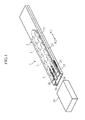
Fig. 1 is an overall perspective view showing one example of a cartridge according to the present invention. -
Fig. 2 is a perspective view showing the cartridge shown inFig. 1 with a case in an exploded manner. -
Fig. 3 is an overall perspective view of a biosensor of the cartridge shown inFig. 1 . -
Fig. 4 is a cross-sectional view taken along line IV-IV ofFig. 3 . -
Fig. 5 is an exploded perspective view of the biosensor shown inFig. 3 . -
Fig. 6 is a cross-sectional view showing the main parts for describing a coupling state of a plurality of biosensors in a cartridge. -
Fig. 7 is a cross-sectional view showing the main parts for describing a hook in the cartridge. -
Fig. 8 is a cross-sectional view showing the main parts for describing a recessed portion in the cartridge. -
Fig. 9 is a cross-sectional view showing the main parts for describing a slit in the cartridge. -
Fig. 10A is an overall perspective view showing one example of an analyzer according to the present invention, andFig. 10B is an overall perspective view showing a state in which the biosensor is attached to the analyzer. -
Fig. 11 is a cross-sectional view taken along line XI-XI ofFig. 10A ; -
Fig. 12 is a perspective view for describing a movable body in the analyzer shown inFig. 10A . -
Fig. 13 is a perspective view for describing the operation of the analyzer and the cartridge. -
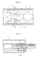
Fig. 14 is a cross-sectional view showing the main parts for describing the operation of the analyzer and the cartridge. -
Fig. 15 is a cross-sectional view showing the main parts for describing the operation of the analyzer and the cartridge. -
Fig. 16 is a cross-sectional view for describing the operation of the cartridge. -
Fig. 17 is a cross-sectional view showing the main parts for describing the operation of the analyzer and the cartridge. -
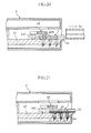
Fig. 18 is a cross-sectional view for describing the operation of the cartridge. -
Fig. 19 is a cross-sectional view showing the main parts for describing the operation of the analyzer and the cartridge. -
Fig. 20 is a cross-sectional view showing the main parts for describing the operation of the analyzer. -
Fig. 21 is a cross-sectional view showing the main parts for describing the operation of the analyzer. -
Fig. 22A is a perspective view for describing another example of a biosensor, andFig. 22A is an exploded perspective view thereof. -
- 1
- Cartridge
- 2
- Case
- 24
- Recessed portion (of case)
- 25
- Hook (holding means)
- 3, 7
- Biosensor (analyzing tool)
- 32
- Engagement projection (projecting portion of engagement means)
- 33
- Engagement hole (recessed portion of engagement means)
- 34
- Through-hole (lock portion)
- 35
- Cutout (holding means)
- 6
- Analyzer
- 68B
- Pin (acting body)
- 68C
- Projection (pressing body)
- N1, N2
- Plane direction
- D1, D2
- Thickness direction (of biosensor)
- The present invention will be specifically described below with reference to the drawings.
- A
cartridge 1 shown inFigs. 1 and2 accommodates a plurality ofbiosensors 3 in acase 2, where thebiosensor 3 is taken out one at a time from the plurality ofbiosensors 3 for use. - As shown in
Figs. 2 to 5 , thebiosensor 3 is used to analyze a specific component (e.g., glucose, cholesterol, or lactic acid) in a sample such as blood and urine by being attached to an analyzer 6 (seeFigs. 10A and 10B ), to be hereinafter described. Thebiosensor 3 is adapted to analyze a sample through electrochemical method, and is formed into a plate-shape as a whole. The plurality ofbiosensors 3 are arranged lined in a longitudinal direction N1, N2 of thecase 2 in thecartridge 1. Eachbiosensor 3 has a projectingportion 30, a recessedportion 31, a pair ofengagement projections 32, a pair of engagement holes 33, a pair of through-holes 34, and a pair ofcutouts 35. - The projecting
portion 30 is the portion (seeFig. 10B ) that projects out from theanalyzer 6 when thebiosensor 3 is attached to theanalyzer 6, and is the portion used when spotting and applying the sample to thebiosensor 3. The recessedportion 31 is the portion for positioning the projectingportion 30 of the adjacentother biosensor 3 in thecartridge 1. In other words, the plurality ofbiosensors 3 can be accommodated in a space efficient manner in thecartridge 1 by lining thebiosensors 3 with the projectingportion 30 positioned in the recessedportion 31. - As shown in
Fig. 6 , the pair ofengagement projections 32 engage theengagement hole 33 of the adjacentother biosensor 3. Theadjacent biosensors 3 can be coupled to each other by engaging theengagement projections 32 to theengagement hole 33 of theadjacent biosensor 3. In this case, theadjacent biosensors 3 are restricted with respect to each other in the longitudinal direction N1, N2, and, on the other hand, are removably attached on the lower side in a thickness direction D1, D2. - As shown in
Fig. 3 , the pair of through-holes 34 are used when taking out thebiosensor 3 from thecartridge 1, and are the portion to be inserted with apin 68B of amovable body 68 in theanalyzer 6, to be hereinafter described. - As shown in
Fig. 7 , the pair ofcutouts 35 hold thebiosensor 3 to be taken out at a predetermined position in thecartridge 1, and prevent thebiosensor 3 from improperly coming out from a take-out port 20 (seeFig. 1 ) of thecartridge 1. The pair ofcutouts 35 are the portion to which ahook 25 of thecase 2 engages. - As shown in
Figs. 3 to 5 , thebiosensor 3 is formed by joining asecond plate material 5 to afirst plate material 4 by way of an adhesive and the like. - The
first plate material 4 is made of an insulating resin material such as PET, and includes a pair offlanges 40, a pair of through-holes 41, andcutouts - The pair of
flanges 40 are the portion to be positioned at thecutout 42 of the otherfirst plate material 5, and are arranged projecting out with respect to thesecond plate material 5.Such flanges 40 have anengagement projection 32 arranged projecting downward. - The pair of through-
holes 41 configure the through-hole 34 in thebiosensor 3, and are formed into an oval shape. - The
cutout 42 is the portion for exposing theengagement hole 33 of thesecond plate material 5, to be hereinafter described, and positioning theflange 40 of thefirst plate material 4 in anotherbiosensor 3. The plurality ofbiosensors 3 can be accommodated in a space efficient manner in thecartridge 1 by positioning theflange 40 of anotherbiosensor 3 in the cutout 42 (seeFigs. 1 and2 ). - The
cutouts 43 configure thecutouts 35 of thebiosensor 3, and are arranged on both sides of thefirst plate material 4. - The
second plate material 5 is made of an insulating resin material such as PET as in thefirst plate material 4, and includes a pair of through-holes 50, a pair of engagement holes 33, a pair ofcutouts 52, and agroove 53. - The pair of through-
holes 50 configure the through-hole 34 of thebiosensor 3, and are provided at positions corresponding to the pair of through-holes 41 of thefirst plate material 4. - As described above, the pair of engagement holes 33 are engaged with the
engagement projection 32 of thefirst plate material 4 in anotherbiosensor 3, and are exposed by thecutout 42 of thefirst plate material 4. - The pair of
cutouts 52 configure thecutout 35 of thebiosensor 3, and are arranged on both sides of thesecond plate material 5 in correspondence to thecutout 43 of thefirst plate material 4. - The
groove 53 moves the sample such as blood supplied to thebiosensor 3. Thegroove 53 configures a capillary 36 when thesecond plate material 5 is stacked on thefirst plate material 4. The capillary 36 is opened at both ends so that capillary force can act. The capillary 36 is introduced with a sample from anend 37, and the sample is moved towards anend 38 by the capillary force in the capillary 36. - The
second plate material 5 is arranged with a workingelectrode 54, acounter electrode 55, adetection electrode 56, and areagent layer 57. - The working
electrode 54 performs electron exchange with the specific component in the sample. Thecounter electrode 55 applies voltage in between the workingelectrode 54. Thedetection electrode 56 detects the supply of sample to the capillary 36. Thedetection electrode 56 detects the supply of sample to the capillary 36 by detecting the current in the case where liquid junction occurs with the workingelectrode 54 or thecounter electrode 55 by the sample. -
Such electrodes 54 to 56 are formed into a columnar shape, where the end faces 54A, 55A, and 56A are exposed on abottom surface 53A of thegroove 53, and the end faces 54B, 55B, and 56B are exposed on abottom surface 5A of thesecond plate material 5. The end faces 54B, 55B, and 56B are portions to which a pin-shapedterminal 69 of theanalyzer 6, to be hereinafter described, is contacted (seeFig. 21 ). - The
electrodes 54 to 56 can be formed by inserting a columnar conductor when resin molding thesecond plate material 5. Various known types generally used for the electrode material can be used for the material of theelectrodes 54 to 56. Such a material includes carbon and the like in addition to a noble metal such as gold, silver and platinum. The material of theelectrodes 54 to 56 may also be that given conductivity by adding metal powder and the like in the resin. Theelectrodes 54 to 56 may be formed by forming a through-hole in thesecond plate material 5, and filling conductor component in the through-hole by screen printing and the like or covering a conductor layer on the through-hole by electroless plating and the like. - The working electrode, the counter electrode, and the detection electrode do not necessarily need to be formed lined in the illustrated order, and the detection electrode may be arranged at the farthest when seen from the
end 37 of the capillary 36 or the detection electrode may be omitted. - The
reagent layer 57 is formed into a solid form that melts when the sample is supplied, and contains, for example, oxidoreductase and an electron transfer substance. The type of oxidoreductase is selected according to the component to be analyzed, where glucose dehydrogenase or glucose oxidase is used when measuring the glucose concentration. Various known types can be used for the electron transfer substance, and for example, Ru complex ([Ru(NH3)6Cl3] etc.) and Fe complex ([K3(CN)6] etc.) may be used. - As shown in
Figs. 1 and2 , thecase 2 accommodates the plurality ofbiosensors 3, and includes the take-outport 20. The take-outport 20 is provided to take out thebiosensor 3 and can be blocked by acap 10. Such acase 2 is formed by attaching acover 22 to abase 21. - The
base 21 is formed into a rectangular shape by resin such as PET, where a recessedportion 24 is formed at anend 23. As shown inFig. 8 , the recessedportion 24 is the portion where thebiosensor 3 to be taken out is positioned when thebiosensor 3 to be taken out and theadjacent biosensor 3 are disengaged. - As shown in
Figs. 1 and2 , thecover 22 defines a space for accommodating the plurality ofbiosensors 3 with thebase 21. Thecover 22 includes a pair ofhooks 25 and a pair ofslits 26. - As shown in
Fig. 7 , the pair ofhooks 25 engage thecutout 35 of thebiosensor 3. Thehook 25 has spring property such that a projectingportion 25A can swing. - As shown in
Fig. 9 , the pair ofslits 26 are used when taking out thebiosensor 3 from thecartridge 1, and are passed through in the thickness direction of thecover 22. More specifically, each slit 26 allows a pair ofpins 68B in theanalyzer 6 to be inserted to the through-holes 34 (41, 50) of thebiosensor 3, and allows the pair ofpins 68B to relatively move with respect to the cartridge 1 (cover 22) with the pair ofpins 68B inserted in the through-holes 34 (41, 50). - The analyzer used with the
cartridge 1 will be described with reference toFigs. 10 to 12 . - As shown in
Fig. 10 , theanalyzer 6 analyzes the sample using thebiosensor 3 of the cartridge 1 (seeFigs. 1 and13 ), and includes aninsertion port 60. Theinsertion port 60 is inserted with the end of thecartridge 1, and is arranged with aguide 61 at a lower position thereof. - The
analyzer 6 has the outer appearance shape defined by ahousing 62. Thehousing 62 includes anupper case 63 and alower case 64, where theinsertion port 60 is formed by cutouts 63A, 63B of thecases - As shown in
Fig. 11 , aspace 65 for inserting the end of thecartridge 1 is formed inside thehousing 62. Thespace 65 is defined by aplate 66 and abase block 67. - The
plate 66 is arranged to cover thebase block 67, and includes aslit 66A. Theslit 66A allows the up and down movement of themovable body 68. - The
movable body 68 takes out thebiosensor 3 from thecartridge 1 or fixes thebiosensor 3 in theanalyzer 6, where the pair ofpins 68B and a pair ofprojections 68C project out from abase plate 68A as shown inFig. 12 . - The pair of
pins 68B are inserted to the pair of through-holes 34 in thebiosensor 3 of thecartridge 1. In other words, thebiosensor 3 can be taken out from thecartridge 1 and retained in thespace 65 of theanalyzer 6 by detaching thecartridge 1 from theanalyzer 6 with thepin 68B inserted in the through-hole 34 (seeFigs. 20 and 21 ). - The pair of
projections 68C fixe thebiosensor 3 in theanalyzer 6. In other words, theprojection 68C can fix thebiosensor 3 in theanalyzer 6 by pressing theflange 40 of thebiosensor 3. - Such a
movable body 68 can reciprocate in the up and down direction by an actuator, a link mechanism, and the like (not shown), and takes a position at which thepin 68B is not inserted to the through-hole 34, a position at which thepin 68B is inserted to the through-hole 34 and theprojection 68C does not press theflange 40, and a position at which theprojection 68C presses theflange 40. Themovable body 68 may obviously be configured to reciprocate in the up and down direction by hand. - As shown in
Fig. 11 , thebase block 67 includes a recessedportion 67A, and can define an insertion depth of thecartridge 1 by the interference of thecartridge 1 with aninner surface 67B. Thebase block 67 is fixed with three pin-shapedterminals 69. - The three pin-shaped
terminals 69 contact theelectrodes 54 to 56 of the biosensor 3 (seeFig. 21 ). Each pin-shapedterminal 69 is biased upward by acoil spring 69B while being fitted inside acylinder 69A, and is movable in the up and down direction. - The analyzing operation of the sample using the cartridge and the
analyzer 6 will now be described with reference toFigs. 13 to 21 . - As shown in
Figs. 13 and14 , thecartridge 1 is first attached to theanalyzer 6 to analyze the sample using theanalyzer 6. Thecartridge 1 is attached to theanalyzer 6 by inserting the take-outport 20 to thespace 65 from theinsertion port 60 of theanalyzer 6. In this case, thecartridge 1 can be smoothly attached to theanalyzer 6 since theguide 61 is formed at theanalyzer 6. When thecartridge 1 is inserted to theanalyzer 6, thecartridge 1 interferes with theinner surface 67B of thebase block 67 thereby regulating the insertion depth of thecartridge 1. - The
movable body 68 is then moved downward, as shown inFigs. 14 and 15 . In this case, since theslits case 2 and theplate 66, thepin 68B of themovable body 68 is inserted to the through-hole 34 of thebiosensor 3 at the farthest end held in thehook 25 of thecartridge 1, as shown inFigs. 15 and16 . - The
cartridge 1 is then moved in a direction N1 of moving away from theanalyzer 6, as shown inFigs. 16 and 17 . In this case, thebiosensor 3 at the farthest end cannot move since thebiosensor 3 has thepin 68B inserted to the through-hole 34. Thus, thehook 25 elastically deforms and displaces to the outer side by the movement force of thecase 2 towards the N1 direction, and thehook 25 separates from thecutout 35 of thebiosensor 3. Thecase 2 is then moved in the N1 direction independent from thebiosensor 3, as shown inFigs. 18 and 19 . - The plurality of
biosensors 3 have theadjacent biosensors 3 coupled by theengagement projection 32 and the engagement hole 33 (seeFig. 6 ), and thus the plurality ofbiosensors 3 relatively move in the N2 direction with respect to thecase 2 when the case is moved in the N1 direction. When thecase 2 is moved by a constant distance with respect to the plurality ofbiosensors 3, thebiosensor 3 is positioned at the recessedportion 24 of thecase 2, and thebiosensor 3 is displaced to the lower side and freed from theother biosensor 3. Meanwhile, thehook 25 of thecase 2 engages thecutout 35 of thebiosensor 3, and thebiosensor 3 to be taken out next is held at a standby position. - As shown in
Fig. 20 , themovable body 68 is further moved downward. The force directed downward acts on thebiosensor 3. Thus, even if not sufficiently freed with respect to thebiosensor 3 to be taken out next, thebiosensor 3 is reliably separated from thebiosensor 3 by the pressing force of themovable body 68. Thebiosensor 3 is then pressed against thebase block 67 by the projection 68e of themovable body 68. Thebiosensor 3 is thereby held in theanalyzer 6. In this case, as shown inFigs. 10B and20 , the projectingportion 30 of thebiosensor 3 is projects out from theanalyzer 6, and each pin-shapedterminal 69 contacts theelectrodes 54 to 56 of thebiosensor 3, as shown inFig. 21 . - When analyzing the sample, the user spots and applies the sample to the projecting
portion 30 of the biosensor 3 (end 37 of capillary 36). The spot application of the sample is carried out by cutting the skin of the subject and bleeding blood and spotting and applying the blood to thebiosensor 3, or by spotting and applying the sample such as urine collected in advance to the projectingportion 30 of thebiosensor 3 using an appropriate spotter. When the sample is spotted and applied to the projectingportion 30 of thebiosensor 3, the sample moves towards theend 38 by the capillary force in the capillary 36, and thereagent layer 57 inside the capillary 36 melts by the sample (seeFig. 4 ). - In the
analyzer 6, whether or not the sample is supplied to thecapillary 36 of thebiosensor 3 is determined. This determination is made by applying voltage through the pin-shapedterminal 69 between thedetection electrode 56 and the working electrode 54 (or counter electrode 55), and by electrically detecting whether or not liquid junction occurred between thedetection electrode 56 and the working electrode 54 (or counter electrode 55). - When determined that the blood is supplied to the capillary 36 is the
analyzer 6, the voltage is applied through the pin-shapedterminal 69 between the workingelectrode 54 and thecounter electrode 55, and the response current in such a case is measured. The response current is correlated to the electron exchange amount between the specific component in the sample and the workingelectrode 54, and thus the concentration of the specific component in the sample can be calculated by the response current. - In the
analyzer 6, the response current after elapse of a constant time from the application of voltage between the workingelectrode 54 and thecounter electrode 55 is sampled, and the concentration of the specific component in the sample is calculated based on the response current value in such a case. This calculation is carried out by applying the sampled response current value to the analytical curve or the correspondence table created in advance. - When the analysis of the sample is terminated in the
analyzer 6, themovable body 68 is moved upward, and the pressing force acting on thebiosensor 3 is released (seeFig. 14 ). Thebiosensor 3 is then freed with respect to theanalyzer 6, and thus, the user can discard thebiosensor 3 from theanalyzer 6 without touching thebiosensor 3 by simply moving theanalyzer 6 to above a discard box, and directing theinsertion port 60 of theanalyzer 6 downward. - The above-described
cartridge 1 is configured to take out thebiosensor 3 using thepin 68B of theanalyzer 6. Thus, in thecartridge 1, a mechanism for taking out thebiosensor 3 is not required, and the user can attach thebiosensor 3 to theanalyzer 6 without touching thebiosensor 3. Thus, the configuration of thecartridge 1 can be simplified, and thebiosensor 3 can be miniaturized since a gripping portion of the user does not need to be provided with respect to thebiosensor 3. As the configuration of thecartridge 1 is simplified and thebiosensor 3 is miniaturized, thecartridge 1 can be miniaturized. In thecartridge 1, the thickness of thecartridge 1 can be significantly reduced since the plurality ofbiosensor 3 are arranged lined in the plane direction. - The
analyzer 6 can take out thebiosensor 3 from thecartridge 1 by themovable body 68 movable in the up and down direction, and hold thebiosensor 3 in theanalyzer 6. Themovable body 68 has an extremely simple configuration equipped with thepin 68B for engaging thebiosensor 3 of thecartridge 1 and theprojection 68C for pressing thebiosensor 3. Thus, the configuration of theanalyzer 6 does not become as complicated and theanalyzer 6 does not becomes as large even if a mechanism for taking out thebiosensor 3 from thecartridge 1 is arranged in theanalyzer 6. - Another example of the biosensor applicable in the cartridge according to the present invention will be described with reference to
Figs. 22A and 22A , where inFigs. 22A and 22A , like reference numerals are denoted for elements having similar functions as in the biosensor (seeFigs. 3 to 5 ) described above, and the redundant description will not be given. - A biosensor 7 shown in
Figs. 22A and 22A includes abase 70 and acover sheet 71. - The
base 70 has the projectingportion 30, the recessedpotion 31, the pair ofengagement projections 32, the pair of engagement holes 33, the pair of through-holes 34, thecutout 35, and thegroove 53 integrally incorporated. Thebase 70 is further provided with the workingelectrode 54, thecounter electrode 55, thedetection electrode 56, and thereagent layer 57. - The
cover sheet 71 is joined to cover thegroove 53. Thus, thecover sheet 71 and thegroove 53 define the capillary 36. Thecover sheet 71 is made of transparent resin film and the like, so that the movement state of the sample such as blood in the capillary 36 can be checked. - In such a biosensor 7, the projecting
portion 30, the recessedportion 31, the pair ofengagement projections 32, the pair of engagement holes 33, the pair of through-holes 34, and thegroove 53 can be incorporated by resin molding, and the workingelectrode 54, thecounter electrode 55, and thedetection electrode 56 can be formed by insert molding. Thereafter, thereagent layer 57 is formed in thegroove 53, and thegroove 53 is covered by thecover sheet 71 to thereby obtain the biosensor 7. The biosensor 7 thus can be very easily manufactured. - The present invention is not limited to the above embodiments, and various modifications may be made. For instance, the present invention is not limited to a biosensor configured as an electrode type, and is applicable even to a cartridge accommodating a plurality of biosensors configured as a colorimetric type. The present invention is also not limited to the biosensor and is also applicable to other analyzing tools.
- Furthermore, the means for coupling the plurality of biosensors in the cartridge is not limited to the combination of a through-hole and a projection, and may be other engagement methods.
- In the present invention, the movable body for taking out the biosensor from the cartridge does not necessarily need to be integrated with the projection for pressing the biosensor. The biosensor also does not necessarily need to be pressed by the projection movable in the up and down direction.
Claims (14)
- A cartridge comprising a plurality of analyzing tools arranged lined in a plane direction and a case for accommodating the plurality of analyzing tools, and being configured to take out the analyzing tool one at a time from the case; wherein
the plurality of analyzing tools further include engagement means for restricting the analyzing tools adjacent to each other in the plane direction and allowing removable attachment in a thickness direction of the analyzing tool. - The cartridge according to claim 1, wherein the engagement means includes a projecting portion projecting out in the thickness direction and a recessed portion to which the projecting portion is inserted.
- The cartridge according to claim 1, further comprising holding means for putting an analyzing tool to be taken out in standby at a target position.
- The cartridge according to claim 3, wherein the holding means includes a recessed portion arranged in the analyzing tool, and a hook arranged in the case.
- The cartridge according to claim 1, wherein the analyzing tool further includes an engagement portion utilized to act a load in a take-out direction on the analyzing tool when taking out from the cartridge.
- The cartridge according to claim 5, wherein the engagement portion is a through-hole.
- The cartridge according to claim 5, wherein the case further includes a slit for allowing movement of an acting body for acting a load on the engagement portion.
- The cartridge according to claim 1, wherein the case further includes a recessed portion for allowing displacement of a position in the thickness direction of the analyzing tool when the analyzing tool is relatively moved in a take-out direction with respect to the case.
- An analyzing system comprising:a cartridge having a plurality of analyzing tools arranged lined in a plane direction accommodated in a case; andan analyzer, attached with the cartridge, for analyzing a sample using the analyzing tool taken out from the cartridge; whereinthe plurality of analyzing tools include engagement means for restricting the analyzing tools adjacent to each other in the plane direction and allowing removable attachment in a thickness direction of the analyzing tool, and an engagement portion utilized to act a load in a take-out direction one the analyzing tool when taking out from the cartridge; andthe analyzer includes an acting body for acting on the engagement portion when taking out the analyzing tool from the cartridge.
- The analyzing system according to claim 9, wherein the acting body reciprocates in the thickness direction of the analyzing tool, and is configured to select a state the load can be acted on the engagement portion and a state the load cannot be acted.
- The analyzing system according to claim 10, wherein the engagement portion is a recessed portion, and the acting body is a projecting portion.
- The analyzing system according to claim 11, wherein the recessed portion is a through-hole, and the projecting portion is a pin.
- The analyzing system according to claim 9, wherein
the case further includes a recessed portion allowing displacement of a position in the thickness direction of the analyzing tool when the analyzing tool is relatively moved in a take-out direction with respect to the case; and the analyzer further includes a pressing body for pressing the analyzing tool in the thickness direction and holding the analyzing tool. - The analyzing system according to claim 13, wherein the pressing body is movable in the thickness direction with the acting body.
Applications Claiming Priority (2)
| Application Number | Priority Date | Filing Date | Title |
|---|---|---|---|
| JP2006300703 | 2006-11-06 | ||
| PCT/JP2007/071522 WO2008056647A1 (en) | 2006-11-06 | 2007-11-06 | Cartridge and analysis system |
Publications (3)
| Publication Number | Publication Date |
|---|---|
| EP2088436A1 true EP2088436A1 (en) | 2009-08-12 |
| EP2088436A4 EP2088436A4 (en) | 2017-02-22 |
| EP2088436B1 EP2088436B1 (en) | 2019-03-06 |
Family
ID=39364462
Family Applications (1)
| Application Number | Title | Priority Date | Filing Date |
|---|---|---|---|
| EP07831254.3A Active EP2088436B1 (en) | 2006-11-06 | 2007-11-06 | Cartridge and analysis system |
Country Status (7)
| Country | Link |
|---|---|
| US (1) | US8313697B2 (en) |
| EP (1) | EP2088436B1 (en) |
| JP (1) | JP5009929B2 (en) |
| KR (1) | KR101017279B1 (en) |
| CN (1) | CN101568839B (en) |
| TW (1) | TWI362492B (en) |
| WO (1) | WO2008056647A1 (en) |
Families Citing this family (4)
| Publication number | Priority date | Publication date | Assignee | Title |
|---|---|---|---|---|
| KR101689890B1 (en) * | 2009-10-26 | 2016-12-26 | 아크레이 인코퍼레이티드 | Sensor cartridge and measuring device |
| JP2012177677A (en) * | 2011-02-02 | 2012-09-13 | Arkray Inc | Analyzer |
| KR101298771B1 (en) | 2011-11-16 | 2013-08-21 | 주식회사 세라젬메디시스 | Cartridge |
| JP6768610B2 (en) * | 2017-08-28 | 2020-10-14 | 富士フイルム株式会社 | Biological sample inspection device |
Family Cites Families (23)
| Publication number | Priority date | Publication date | Assignee | Title |
|---|---|---|---|---|
| JP2510702Y2 (en) * | 1989-12-07 | 1996-09-18 | 株式会社エー・アンド・デイ | Disposable chemical sensor |
| FR2701117B1 (en) * | 1993-02-04 | 1995-03-10 | Asulab Sa | Electrochemical measurement system with multizone sensor, and its application to glucose measurement. |
| DE4313253A1 (en) * | 1993-04-23 | 1994-10-27 | Boehringer Mannheim Gmbh | System for analyzing the contents of liquid samples |
| FR2733745B1 (en) * | 1995-05-02 | 1997-07-04 | Asulab Sa | IMPROVED APPARATUS FOR THE DISTRIBUTION OF SUCCESSIVE AREAS OF A CONSUMABLE BAND |
| JPH08302314A (en) | 1995-05-08 | 1996-11-19 | Kao Corp | Nonwoven fabric binder, nonwoven fabric for floppy disk liner using the same, method for producing the same, and floppy disk |
| US5882611A (en) | 1997-06-02 | 1999-03-16 | Ethicon, Inc. | Cassette and delivery system |
| JP3896435B2 (en) * | 1997-12-17 | 2007-03-22 | アークレイ株式会社 | Sensor and sensor assembly |
| DE19811622A1 (en) * | 1998-03-17 | 1999-09-23 | Lre Technology Partner Gmbh | Laboratory instrument incorporating split test card housing |
| JP3922503B2 (en) * | 1999-03-30 | 2007-05-30 | 三協立山アルミ株式会社 | Draw sash |
| HK1053151B (en) * | 2000-03-28 | 2006-05-26 | Diabetes Diagnostics, Inc. | Continuous process for manufacture of disposable electro-chemical sensor |
| JP2002039990A (en) * | 2000-07-21 | 2002-02-06 | Fuji Photo Film Co Ltd | Ion-selective electrode and its manufacturing method |
| US7101512B2 (en) | 2000-12-15 | 2006-09-05 | Ethicon, Inc. | Cassette and delivery system |
| US6558528B1 (en) * | 2000-12-20 | 2003-05-06 | Lifescan, Inc. | Electrochemical test strip cards that include an integral dessicant |
| JP4143753B2 (en) | 2002-04-05 | 2008-09-03 | アークレイ株式会社 | Analysis tool cartridge with take-out mechanism, and set of this and analyzer |
| JP4257943B2 (en) * | 2002-07-29 | 2009-04-30 | アークレイ株式会社 | Puncture unit and puncture member removal tool |
| DE10244775A1 (en) * | 2002-09-26 | 2004-04-08 | Roche Diagnostics Gmbh | Capillary sensor analysis system |
| US7544277B2 (en) * | 2003-06-12 | 2009-06-09 | Bayer Healthcare, Llc | Electrochemical test sensors |
| HUE039852T2 (en) * | 2003-06-20 | 2019-02-28 | Hoffmann La Roche | Method and reagent for producing narrow, homogenous reagent strips |
| WO2005098431A1 (en) * | 2004-03-05 | 2005-10-20 | Egomedical Swiss Ag | Analyte test system for determining the concentration of an analyte in a physiological fluid |
| US7512432B2 (en) * | 2004-07-27 | 2009-03-31 | Abbott Laboratories | Sensor array |
| DE102004050062A1 (en) * | 2004-10-13 | 2006-04-27 | Boehringer Ingelheim Microparts Gmbh | Apparatus, meter and method for receiving and assaying or manipulating sample fluids in a microfluidic platform |
| JP5289666B2 (en) * | 2005-01-24 | 2013-09-11 | 住友電気工業株式会社 | Sensor chip assembly and manufacturing method thereof |
| US20080044879A1 (en) * | 2006-08-17 | 2008-02-21 | The Charles Stark Draper Laboratory, Inc. | Systems and methods of voltage-gated ion channel assays |
-
2007
- 2007-11-06 US US12/312,330 patent/US8313697B2/en not_active Expired - Fee Related
- 2007-11-06 TW TW096141884A patent/TWI362492B/en active
- 2007-11-06 CN CN2007800410964A patent/CN101568839B/en active Active
- 2007-11-06 WO PCT/JP2007/071522 patent/WO2008056647A1/en not_active Ceased
- 2007-11-06 EP EP07831254.3A patent/EP2088436B1/en active Active
- 2007-11-06 KR KR1020097007549A patent/KR101017279B1/en active Active
- 2007-11-06 JP JP2008543074A patent/JP5009929B2/en active Active
Non-Patent Citations (1)
| Title |
|---|
| See references of WO2008056647A1 * |
Also Published As
| Publication number | Publication date |
|---|---|
| EP2088436B1 (en) | 2019-03-06 |
| TWI362492B (en) | 2012-04-21 |
| JP5009929B2 (en) | 2012-08-29 |
| US8313697B2 (en) | 2012-11-20 |
| JPWO2008056647A1 (en) | 2010-02-25 |
| CN101568839B (en) | 2012-07-04 |
| EP2088436A4 (en) | 2017-02-22 |
| KR20090069295A (en) | 2009-06-30 |
| TW200834075A (en) | 2008-08-16 |
| CN101568839A (en) | 2009-10-28 |
| WO2008056647A1 (en) | 2008-05-15 |
| US20100196201A1 (en) | 2010-08-05 |
| KR101017279B1 (en) | 2011-02-28 |
Similar Documents
| Publication | Publication Date | Title |
|---|---|---|
| JP2009525794A (en) | Personal portable blood glucose meter with replaceable specimen cartridge | |
| CN100406878C (en) | Analytical tool carrier with take-out mechanism and matching combination with analytical device | |
| KR100824612B1 (en) | Analysis device | |
| US20110040160A1 (en) | Analysis device having a discarding mechanism | |
| EP2261674A1 (en) | Portable analytical instrument | |
| EP2315012B1 (en) | Sensor cartridge and measuring device | |
| US8313697B2 (en) | Cartridge and analyzing system | |
| KR101470370B1 (en) | Analyzer | |
| EP1828769B1 (en) | Contact connector assembly for a sensor-dispensing instrument | |
| CN108344771A (en) | Test piece reading device | |
| WO2005047877A1 (en) | Electrochemical sensing device | |
| EP3581924A1 (en) | Measurement apparatus and measurement system | |
| KR20100031567A (en) | Analyzing system | |
| JP5514464B2 (en) | Component measuring device | |
| US20050115831A1 (en) | Eletrochemical sensing device | |
| KR100873013B1 (en) | Analyzer and method of manufacturing the same | |
| JP2007327783A (en) | Test paper magazine, magazine holder and test paper loading device | |
| KR20100032364A (en) | Analysis device | |
| CN203053913U (en) | Biosensor system | |
| JP4853947B2 (en) | Biosensor |
Legal Events
| Date | Code | Title | Description |
|---|---|---|---|
| PUAI | Public reference made under article 153(3) epc to a published international application that has entered the european phase |
Free format text: ORIGINAL CODE: 0009012 |
|
| 17P | Request for examination filed |
Effective date: 20090528 |
|
| AK | Designated contracting states |
Kind code of ref document: A1 Designated state(s): AT BE BG CH CY CZ DE DK EE ES FI FR GB GR HU IE IS IT LI LT LU LV MC MT NL PL PT RO SE SI SK TR |
|
| DAX | Request for extension of the european patent (deleted) | ||
| RAP1 | Party data changed (applicant data changed or rights of an application transferred) |
Owner name: ARKRAY, INC. |
|
| RA4 | Supplementary search report drawn up and despatched (corrected) |
Effective date: 20170124 |
|
| RIC1 | Information provided on ipc code assigned before grant |
Ipc: G01N 35/02 20060101AFI20170118BHEP Ipc: G01N 27/28 20060101ALI20170118BHEP Ipc: G01N 27/327 20060101ALI20170118BHEP Ipc: G01N 1/00 20060101ALI20170118BHEP |
|
| STAA | Information on the status of an ep patent application or granted ep patent |
Free format text: STATUS: EXAMINATION IS IN PROGRESS |
|
| 17Q | First examination report despatched |
Effective date: 20180620 |
|
| REG | Reference to a national code |
Ref country code: DE Ref legal event code: R079 Ref document number: 602007057798 Country of ref document: DE Free format text: PREVIOUS MAIN CLASS: G01N0035020000 Ipc: G01N0033487000 |
|
| RIC1 | Information provided on ipc code assigned before grant |
Ipc: G01N 33/487 20060101AFI20180823BHEP |
|
| GRAP | Despatch of communication of intention to grant a patent |
Free format text: ORIGINAL CODE: EPIDOSNIGR1 |
|
| STAA | Information on the status of an ep patent application or granted ep patent |
Free format text: STATUS: GRANT OF PATENT IS INTENDED |
|
| INTG | Intention to grant announced |
Effective date: 20181018 |
|
| GRAS | Grant fee paid |
Free format text: ORIGINAL CODE: EPIDOSNIGR3 |
|
| GRAA | (expected) grant |
Free format text: ORIGINAL CODE: 0009210 |
|
| STAA | Information on the status of an ep patent application or granted ep patent |
Free format text: STATUS: THE PATENT HAS BEEN GRANTED |
|
| AK | Designated contracting states |
Kind code of ref document: B1 Designated state(s): AT BE BG CH CY CZ DE DK EE ES FI FR GB GR HU IE IS IT LI LT LU LV MC MT NL PL PT RO SE SI SK TR |
|
| REG | Reference to a national code |
Ref country code: GB Ref legal event code: FG4D |
|
| REG | Reference to a national code |
Ref country code: CH Ref legal event code: EP Ref country code: AT Ref legal event code: REF Ref document number: 1105230 Country of ref document: AT Kind code of ref document: T Effective date: 20190315 |
|
| REG | Reference to a national code |
Ref country code: DE Ref legal event code: R096 Ref document number: 602007057798 Country of ref document: DE |
|
| REG | Reference to a national code |
Ref country code: IE Ref legal event code: FG4D |
|
| REG | Reference to a national code |
Ref country code: NL Ref legal event code: MP Effective date: 20190306 |
|
| REG | Reference to a national code |
Ref country code: LT Ref legal event code: MG4D |
|
| PG25 | Lapsed in a contracting state [announced via postgrant information from national office to epo] |
Ref country code: FI Free format text: LAPSE BECAUSE OF FAILURE TO SUBMIT A TRANSLATION OF THE DESCRIPTION OR TO PAY THE FEE WITHIN THE PRESCRIBED TIME-LIMIT Effective date: 20190306 Ref country code: LT Free format text: LAPSE BECAUSE OF FAILURE TO SUBMIT A TRANSLATION OF THE DESCRIPTION OR TO PAY THE FEE WITHIN THE PRESCRIBED TIME-LIMIT Effective date: 20190306 Ref country code: SE Free format text: LAPSE BECAUSE OF FAILURE TO SUBMIT A TRANSLATION OF THE DESCRIPTION OR TO PAY THE FEE WITHIN THE PRESCRIBED TIME-LIMIT Effective date: 20190306 |
|
| PG25 | Lapsed in a contracting state [announced via postgrant information from national office to epo] |
Ref country code: NL Free format text: LAPSE BECAUSE OF FAILURE TO SUBMIT A TRANSLATION OF THE DESCRIPTION OR TO PAY THE FEE WITHIN THE PRESCRIBED TIME-LIMIT Effective date: 20190306 Ref country code: LV Free format text: LAPSE BECAUSE OF FAILURE TO SUBMIT A TRANSLATION OF THE DESCRIPTION OR TO PAY THE FEE WITHIN THE PRESCRIBED TIME-LIMIT Effective date: 20190306 Ref country code: GR Free format text: LAPSE BECAUSE OF FAILURE TO SUBMIT A TRANSLATION OF THE DESCRIPTION OR TO PAY THE FEE WITHIN THE PRESCRIBED TIME-LIMIT Effective date: 20190607 Ref country code: BG Free format text: LAPSE BECAUSE OF FAILURE TO SUBMIT A TRANSLATION OF THE DESCRIPTION OR TO PAY THE FEE WITHIN THE PRESCRIBED TIME-LIMIT Effective date: 20190606 |
|
| REG | Reference to a national code |
Ref country code: AT Ref legal event code: MK05 Ref document number: 1105230 Country of ref document: AT Kind code of ref document: T Effective date: 20190306 |
|
| PG25 | Lapsed in a contracting state [announced via postgrant information from national office to epo] |
Ref country code: EE Free format text: LAPSE BECAUSE OF FAILURE TO SUBMIT A TRANSLATION OF THE DESCRIPTION OR TO PAY THE FEE WITHIN THE PRESCRIBED TIME-LIMIT Effective date: 20190306 Ref country code: CZ Free format text: LAPSE BECAUSE OF FAILURE TO SUBMIT A TRANSLATION OF THE DESCRIPTION OR TO PAY THE FEE WITHIN THE PRESCRIBED TIME-LIMIT Effective date: 20190306 Ref country code: RO Free format text: LAPSE BECAUSE OF FAILURE TO SUBMIT A TRANSLATION OF THE DESCRIPTION OR TO PAY THE FEE WITHIN THE PRESCRIBED TIME-LIMIT Effective date: 20190306 Ref country code: PT Free format text: LAPSE BECAUSE OF FAILURE TO SUBMIT A TRANSLATION OF THE DESCRIPTION OR TO PAY THE FEE WITHIN THE PRESCRIBED TIME-LIMIT Effective date: 20190706 Ref country code: ES Free format text: LAPSE BECAUSE OF FAILURE TO SUBMIT A TRANSLATION OF THE DESCRIPTION OR TO PAY THE FEE WITHIN THE PRESCRIBED TIME-LIMIT Effective date: 20190306 Ref country code: SK Free format text: LAPSE BECAUSE OF FAILURE TO SUBMIT A TRANSLATION OF THE DESCRIPTION OR TO PAY THE FEE WITHIN THE PRESCRIBED TIME-LIMIT Effective date: 20190306 |
|
| PG25 | Lapsed in a contracting state [announced via postgrant information from national office to epo] |
Ref country code: PL Free format text: LAPSE BECAUSE OF FAILURE TO SUBMIT A TRANSLATION OF THE DESCRIPTION OR TO PAY THE FEE WITHIN THE PRESCRIBED TIME-LIMIT Effective date: 20190306 |
|
| REG | Reference to a national code |
Ref country code: DE Ref legal event code: R097 Ref document number: 602007057798 Country of ref document: DE |
|
| PG25 | Lapsed in a contracting state [announced via postgrant information from national office to epo] |
Ref country code: AT Free format text: LAPSE BECAUSE OF FAILURE TO SUBMIT A TRANSLATION OF THE DESCRIPTION OR TO PAY THE FEE WITHIN THE PRESCRIBED TIME-LIMIT Effective date: 20190306 Ref country code: IS Free format text: LAPSE BECAUSE OF FAILURE TO SUBMIT A TRANSLATION OF THE DESCRIPTION OR TO PAY THE FEE WITHIN THE PRESCRIBED TIME-LIMIT Effective date: 20190706 |
|
| PLBE | No opposition filed within time limit |
Free format text: ORIGINAL CODE: 0009261 |
|
| STAA | Information on the status of an ep patent application or granted ep patent |
Free format text: STATUS: NO OPPOSITION FILED WITHIN TIME LIMIT |
|
| PG25 | Lapsed in a contracting state [announced via postgrant information from national office to epo] |
Ref country code: DK Free format text: LAPSE BECAUSE OF FAILURE TO SUBMIT A TRANSLATION OF THE DESCRIPTION OR TO PAY THE FEE WITHIN THE PRESCRIBED TIME-LIMIT Effective date: 20190306 |
|
| 26N | No opposition filed |
Effective date: 20191209 |
|
| PG25 | Lapsed in a contracting state [announced via postgrant information from national office to epo] |
Ref country code: SI Free format text: LAPSE BECAUSE OF FAILURE TO SUBMIT A TRANSLATION OF THE DESCRIPTION OR TO PAY THE FEE WITHIN THE PRESCRIBED TIME-LIMIT Effective date: 20190306 |
|
| PG25 | Lapsed in a contracting state [announced via postgrant information from national office to epo] |
Ref country code: TR Free format text: LAPSE BECAUSE OF FAILURE TO SUBMIT A TRANSLATION OF THE DESCRIPTION OR TO PAY THE FEE WITHIN THE PRESCRIBED TIME-LIMIT Effective date: 20190306 |
|
| REG | Reference to a national code |
Ref country code: CH Ref legal event code: PL |
|
| PG25 | Lapsed in a contracting state [announced via postgrant information from national office to epo] |
Ref country code: CH Free format text: LAPSE BECAUSE OF NON-PAYMENT OF DUE FEES Effective date: 20191130 Ref country code: MC Free format text: LAPSE BECAUSE OF FAILURE TO SUBMIT A TRANSLATION OF THE DESCRIPTION OR TO PAY THE FEE WITHIN THE PRESCRIBED TIME-LIMIT Effective date: 20190306 Ref country code: LU Free format text: LAPSE BECAUSE OF NON-PAYMENT OF DUE FEES Effective date: 20191106 Ref country code: LI Free format text: LAPSE BECAUSE OF NON-PAYMENT OF DUE FEES Effective date: 20191130 |
|
| REG | Reference to a national code |
Ref country code: BE Ref legal event code: MM Effective date: 20191130 |
|
| PG25 | Lapsed in a contracting state [announced via postgrant information from national office to epo] |
Ref country code: IE Free format text: LAPSE BECAUSE OF NON-PAYMENT OF DUE FEES Effective date: 20191106 |
|
| PG25 | Lapsed in a contracting state [announced via postgrant information from national office to epo] |
Ref country code: BE Free format text: LAPSE BECAUSE OF NON-PAYMENT OF DUE FEES Effective date: 20191130 |
|
| PG25 | Lapsed in a contracting state [announced via postgrant information from national office to epo] |
Ref country code: CY Free format text: LAPSE BECAUSE OF FAILURE TO SUBMIT A TRANSLATION OF THE DESCRIPTION OR TO PAY THE FEE WITHIN THE PRESCRIBED TIME-LIMIT Effective date: 20190306 |
|
| PG25 | Lapsed in a contracting state [announced via postgrant information from national office to epo] |
Ref country code: HU Free format text: LAPSE BECAUSE OF FAILURE TO SUBMIT A TRANSLATION OF THE DESCRIPTION OR TO PAY THE FEE WITHIN THE PRESCRIBED TIME-LIMIT; INVALID AB INITIO Effective date: 20071106 Ref country code: MT Free format text: LAPSE BECAUSE OF FAILURE TO SUBMIT A TRANSLATION OF THE DESCRIPTION OR TO PAY THE FEE WITHIN THE PRESCRIBED TIME-LIMIT Effective date: 20190306 |
|
| PGFP | Annual fee paid to national office [announced via postgrant information from national office to epo] |
Ref country code: DE Payment date: 20241121 Year of fee payment: 18 |
|
| PGFP | Annual fee paid to national office [announced via postgrant information from national office to epo] |
Ref country code: GB Payment date: 20241120 Year of fee payment: 18 |
|
| PGFP | Annual fee paid to national office [announced via postgrant information from national office to epo] |
Ref country code: FR Payment date: 20241128 Year of fee payment: 18 |
|
| PGFP | Annual fee paid to national office [announced via postgrant information from national office to epo] |
Ref country code: IT Payment date: 20241126 Year of fee payment: 18 |