EP2088381A1 - Air conditioner and method of controlling humidity in room - Google Patents
Air conditioner and method of controlling humidity in room Download PDFInfo
- Publication number
- EP2088381A1 EP2088381A1 EP07831394A EP07831394A EP2088381A1 EP 2088381 A1 EP2088381 A1 EP 2088381A1 EP 07831394 A EP07831394 A EP 07831394A EP 07831394 A EP07831394 A EP 07831394A EP 2088381 A1 EP2088381 A1 EP 2088381A1
- Authority
- EP
- European Patent Office
- Prior art keywords
- humidity
- indoor
- target
- air
- unit
- Prior art date
- Legal status (The legal status is an assumption and is not a legal conclusion. Google has not performed a legal analysis and makes no representation as to the accuracy of the status listed.)
- Granted
Links
- 238000000034 method Methods 0.000 title claims abstract description 10
- 230000000977 initiatory effect Effects 0.000 claims description 10
- 238000010438 heat treatment Methods 0.000 claims description 7
- 238000001816 cooling Methods 0.000 claims description 6
- 210000004400 mucous membrane Anatomy 0.000 claims description 6
- 238000004378 air conditioning Methods 0.000 abstract description 11
- 230000001143 conditioned effect Effects 0.000 abstract 1
- 230000002618 waking effect Effects 0.000 description 25
- 239000003507 refrigerant Substances 0.000 description 23
- 230000035900 sweating Effects 0.000 description 12
- 230000009471 action Effects 0.000 description 8
- 230000006870 function Effects 0.000 description 8
- 238000001179 sorption measurement Methods 0.000 description 8
- 230000007423 decrease Effects 0.000 description 5
- 238000010586 diagram Methods 0.000 description 5
- 230000000694 effects Effects 0.000 description 4
- 230000009467 reduction Effects 0.000 description 4
- 230000033764 rhythmic process Effects 0.000 description 4
- 239000003463 adsorbent Substances 0.000 description 3
- 230000036760 body temperature Effects 0.000 description 3
- 230000008859 change Effects 0.000 description 3
- 230000036757 core body temperature Effects 0.000 description 3
- 229910021536 Zeolite Inorganic materials 0.000 description 2
- 238000006243 chemical reaction Methods 0.000 description 2
- HNPSIPDUKPIQMN-UHFFFAOYSA-N dioxosilane;oxo(oxoalumanyloxy)alumane Chemical compound O=[Si]=O.O=[Al]O[Al]=O HNPSIPDUKPIQMN-UHFFFAOYSA-N 0.000 description 2
- 230000002093 peripheral effect Effects 0.000 description 2
- 239000010457 zeolite Substances 0.000 description 2
- 206010022035 Initial insomnia Diseases 0.000 description 1
- VYPSYNLAJGMNEJ-UHFFFAOYSA-N Silicium dioxide Chemical compound O=[Si]=O VYPSYNLAJGMNEJ-UHFFFAOYSA-N 0.000 description 1
- PNEYBMLMFCGWSK-UHFFFAOYSA-N aluminium oxide Inorganic materials [O-2].[O-2].[O-2].[Al+3].[Al+3] PNEYBMLMFCGWSK-UHFFFAOYSA-N 0.000 description 1
- 239000000919 ceramic Substances 0.000 description 1
- 230000003750 conditioning effect Effects 0.000 description 1
- 230000003247 decreasing effect Effects 0.000 description 1
- 238000007599 discharging Methods 0.000 description 1
- 238000010981 drying operation Methods 0.000 description 1
- 239000007788 liquid Substances 0.000 description 1
- 230000004048 modification Effects 0.000 description 1
- 238000012986 modification Methods 0.000 description 1
- 230000035807 sensation Effects 0.000 description 1
- 239000000741 silica gel Substances 0.000 description 1
- 229910002027 silica gel Inorganic materials 0.000 description 1
- XLYOFNOQVPJJNP-UHFFFAOYSA-N water Substances O XLYOFNOQVPJJNP-UHFFFAOYSA-N 0.000 description 1
Images




Classifications
-
- F—MECHANICAL ENGINEERING; LIGHTING; HEATING; WEAPONS; BLASTING
- F24—HEATING; RANGES; VENTILATING
- F24F—AIR-CONDITIONING; AIR-HUMIDIFICATION; VENTILATION; USE OF AIR CURRENTS FOR SCREENING
- F24F11/00—Control or safety arrangements
- F24F11/0008—Control or safety arrangements for air-humidification
-
- F—MECHANICAL ENGINEERING; LIGHTING; HEATING; WEAPONS; BLASTING
- F24—HEATING; RANGES; VENTILATING
- F24F—AIR-CONDITIONING; AIR-HUMIDIFICATION; VENTILATION; USE OF AIR CURRENTS FOR SCREENING
- F24F1/00—Room units for air-conditioning, e.g. separate or self-contained units or units receiving primary air from a central station
- F24F1/0003—Room units for air-conditioning, e.g. separate or self-contained units or units receiving primary air from a central station characterised by a split arrangement, wherein parts of the air-conditioning system, e.g. evaporator and condenser, are in separately located units
-
- F—MECHANICAL ENGINEERING; LIGHTING; HEATING; WEAPONS; BLASTING
- F24—HEATING; RANGES; VENTILATING
- F24F—AIR-CONDITIONING; AIR-HUMIDIFICATION; VENTILATION; USE OF AIR CURRENTS FOR SCREENING
- F24F11/00—Control or safety arrangements
- F24F11/30—Control or safety arrangements for purposes related to the operation of the system, e.g. for safety or monitoring
-
- F—MECHANICAL ENGINEERING; LIGHTING; HEATING; WEAPONS; BLASTING
- F24—HEATING; RANGES; VENTILATING
- F24F—AIR-CONDITIONING; AIR-HUMIDIFICATION; VENTILATION; USE OF AIR CURRENTS FOR SCREENING
- F24F11/00—Control or safety arrangements
- F24F11/62—Control or safety arrangements characterised by the type of control or by internal processing, e.g. using fuzzy logic, adaptive control or estimation of values
- F24F11/63—Electronic processing
- F24F11/65—Electronic processing for selecting an operating mode
- F24F11/66—Sleep mode
-
- F—MECHANICAL ENGINEERING; LIGHTING; HEATING; WEAPONS; BLASTING
- F24—HEATING; RANGES; VENTILATING
- F24F—AIR-CONDITIONING; AIR-HUMIDIFICATION; VENTILATION; USE OF AIR CURRENTS FOR SCREENING
- F24F3/00—Air-conditioning systems in which conditioned primary air is supplied from one or more central stations to distributing units in the rooms or spaces where it may receive secondary treatment; Apparatus specially designed for such systems
- F24F3/12—Air-conditioning systems in which conditioned primary air is supplied from one or more central stations to distributing units in the rooms or spaces where it may receive secondary treatment; Apparatus specially designed for such systems characterised by the treatment of the air otherwise than by heating and cooling
- F24F3/14—Air-conditioning systems in which conditioned primary air is supplied from one or more central stations to distributing units in the rooms or spaces where it may receive secondary treatment; Apparatus specially designed for such systems characterised by the treatment of the air otherwise than by heating and cooling by humidification; by dehumidification
- F24F3/1411—Air-conditioning systems in which conditioned primary air is supplied from one or more central stations to distributing units in the rooms or spaces where it may receive secondary treatment; Apparatus specially designed for such systems characterised by the treatment of the air otherwise than by heating and cooling by humidification; by dehumidification by absorbing or adsorbing water, e.g. using an hygroscopic desiccant
- F24F3/1423—Air-conditioning systems in which conditioned primary air is supplied from one or more central stations to distributing units in the rooms or spaces where it may receive secondary treatment; Apparatus specially designed for such systems characterised by the treatment of the air otherwise than by heating and cooling by humidification; by dehumidification by absorbing or adsorbing water, e.g. using an hygroscopic desiccant with a moving bed of solid desiccants, e.g. a rotary wheel supporting solid desiccants
-
- F—MECHANICAL ENGINEERING; LIGHTING; HEATING; WEAPONS; BLASTING
- F24—HEATING; RANGES; VENTILATING
- F24F—AIR-CONDITIONING; AIR-HUMIDIFICATION; VENTILATION; USE OF AIR CURRENTS FOR SCREENING
- F24F11/00—Control or safety arrangements
- F24F11/62—Control or safety arrangements characterised by the type of control or by internal processing, e.g. using fuzzy logic, adaptive control or estimation of values
- F24F11/63—Electronic processing
- F24F11/65—Electronic processing for selecting an operating mode
-
- F—MECHANICAL ENGINEERING; LIGHTING; HEATING; WEAPONS; BLASTING
- F24—HEATING; RANGES; VENTILATING
- F24F—AIR-CONDITIONING; AIR-HUMIDIFICATION; VENTILATION; USE OF AIR CURRENTS FOR SCREENING
- F24F2110/00—Control inputs relating to air properties
- F24F2110/20—Humidity
Definitions
- the present invention relates to an air conditioner, and particularly to an air conditioner having a regular mode and a sleep mode.
- the present invention also relates to an indoor humidity control method for controlling indoor humidity.
- modem air conditioners have various functions, such as a regular mode for making indoor temperature and humidity more comfortable, and a sleep mode for bedtime.
- Sleep mode is a function for conditioning indoor air so that a user can sleep comfortably.
- An air conditioner having the sleep mode is an air conditioner for adjusting indoor temperature in accordance with a user's biological rhythms during sleep, such as the air conditioner disclosed in patent document 1, for example.
- Patent Document 1 Japanese Laid-open Patent Document No. 5-106899
- Examples of biological rhythms during sleep include those pertaining to temperature, such as the core body temperature decreasing when falling asleep and the body temperature returning to normal when awakening, as well as making it easier to fall asleep by sweating. Therefore, even if the temperature is adjusted in the same manner as with the air conditioner of patent document 1, the user has trouble falling asleep in cases of high indoor humidity because it is difficult for sweating to occur. The lower the indoor humidity when the user awakens, the thirstier the user is or the less moisture there is in the user's skin. During the winter season when the air is dry, these phenomena are particularly prominent.
- the present invention provides an air conditioner and a humidity control method whereby the indoor air can be adjusted so that a user indoors can sleep comfortably when a sleep mode has been set by the user.
- An air conditioner is an air conditioner having a regular mode and a sleep mode.
- the air conditioner comprises a humidity adjustment unit and a humidity control unit.
- the humidity adjustment unit humidifies or dehumidifies air and supplies the air into a room.
- the humidity control unit controls the humidity adjustment unit during the regular mode so that the indoor humidity reaches a first target humidity.
- the humidity control unit also controls the humidity adjustment unit during the sleep mode so that the indoor humidity reaches a second target humidity, which is lower than the first target humidity.
- a user intending to sleep in a room provided with this air conditioner may set the air conditioner to the sleep mode.
- the air conditioner sets the indoor target humidity to be lower than during the regular mode.
- the indoor humidity is thereby set to a lower humidity than during the regular mode. Sweating is therefore promoted, and the user can sleep deeply.
- An air conditioner according to a second aspect is the air conditioner according to the first aspect, wherein the second target humidity is within a range that is higher than the humidity at which the oral mucous membrane dries up and lower than the humidity at which mold forms.
- the room interior is thereby maintained at a comfortable humidity level for a user falling asleep in cases in which the air conditioner has been set to the sleep mode.
- An air conditioner according to a third aspect is the air conditioner according to the first or second aspect, wherein the second target humidity is an absolute humidity.
- the air conditioner according to the third aspect uses absolute humidity as the target humidity and controls in accordance with the absolute humidity, or the relative humidity in a manner equivalent to the absolute humidity, so that the indoor humidity reaches the target humidity.
- the room interior thereby reaches a comfortable humidity level for a user falling asleep.
- An air conditioner according to a fourth aspect is the air conditioner according to any of the first through third aspects, further comprising a temperature adjustment unit and a temperature control unit.
- the temperature adjustment unit cools or heats air to adjust the indoor temperature.
- the temperature control unit controls the temperature adjustment unit during the sleep mode so that the indoor temperature reaches a second target temperature, which is below a first target temperature set during the regular mode.
- the air conditioner further controls the temperature so that the indoor temperature decreases in accordance with the decrease in a user's core body temperature when the user is sleeping, for example.
- the user can sleep deeply due to the temperature being controlled in addition to the humidity when the user is falling asleep.
- An air conditioner is an air conditioner having a regular mode and a sleep mode.
- the air conditioner comprises a humidity adjustment unit, a command receive unit, and a humidity control unit.
- the humidity adjustment unit humidifies or dehumidifies air and supplies the air into a room.
- the command receive unit receives operation initiation commands for the regular mode or the sleep mode.
- the humidity control unit controls the humidity adjustment unit so that the indoor humidity reaches a third target humidity when the command receive unit has received a command to initiate the regular mode operation.
- the humidity control unit also controls the humidity adjustment unit so that the indoor humidity reaches a fourth target humidity, which is higher than the third target humidity, when a predetermined time period has passed after the command receive unit received a command to initiate the sleep mode operation.
- a user intending to sleep in a room provided with this air conditioner may set the air conditioner to the sleep mode.
- the air conditioner adjusts the indoor target humidity to be higher than during the regular mode when a predetermined time period has passed after the sleep mode operation was initiated.
- the indoor humidity is thereby set to a higher humidity than during the regular mode when the user wakes up. Consequently, sweating in the user is suppressed, as is skin or throat dryness.
- An air conditioner according to a sixth aspect is the air conditioner according to the fifth aspect, wherein the fourth target humidity is within a range that is higher than the humidity at which the oral mucous membrane dries up and lower than the humidity at which mold forms.
- the room interior is thereby maintained at a humidity at which an appropriate amount of moisture is contained in the user's skin or throat when the user wakes up.
- An air conditioner according to a seventh aspect is the air conditioner according to the fifth or sixth aspect, wherein the fourth target humidity is an absolute humidity.
- the air conditioner according to the seventh aspect uses absolute humidity as the target humidity and controls in accordance with the absolute humidity, or the relative humidity in a manner equivalent to the absolute humidity, so that the indoor humidity reaches the target humidity. The user can thereby be woken up with a more appropriate amount of moisture in the skin and throat.
- An air conditioner according to an eighth aspect is the air conditioner according to any of the fifth through seventh aspects, further comprising a temperature adjustment unit and a temperature control unit.
- the temperature adjustment unit heats or cools air to adjust the indoor temperature.
- the temperature control unit controls the temperature adjustment unit so that the indoor temperature reaches a fourth target temperature, which is below a third target temperature set during the regular mode, when the command receive unit has received a command to initiate the sleep mode operation.
- the temperature control unit also controls the temperature adjustment unit so that the indoor temperature reaches the third target temperature when at least the predetermined time period has passed after the command receive unit received the command to initiate the sleep mode operation.
- the air conditioner further controls the temperature so that the lowered indoor temperature is raised in accordance with the increase in the user's body temperature when the user wakes up, for example.
- the user can be woken up more comfortably by controlling the temperature in addition to humidity during waking.
- a humidity control method is a method for controlling indoor humidity so that the indoor humidity during a regular mode reaches a fifth target humidity.
- the humidity control method comprises steps 1 through 3.
- Step 1 is a step for receiving a command to initiate a sleep mode operation.
- Step 2 is a step for dehumidifying or humidifying air and supplying the air into a room so that the indoor humidity reaches a sixth target humidity, which is lower than the fifth target humidity.
- Step 3 is a step for humidifying air and supplying the air into the room so that the indoor humidity reaches a seventh target humidity, which is higher than the fifth target humidity, when a predetermined time period has passed after the operation initiation command was received.
- Sweating is thereby promoted when the user is falling asleep because the indoor humidity is lower than the humidity during the regular mode. Consequently, the user can sleep deeply.
- the indoor humidity is thereby higher than the humidity during the regular mode when the user wakes up, and sweating in the user is therefore suppressed, as is skin and throat dryness.
- the room interior is maintained at a humidity at which a user can fall asleep comfortably.
- the room interior reaches a more comfortable humidity when the user is falling asleep.
- the user can sleep more deeply because the temperature is controlled in addition to the humidity when the user is falling asleep.
- the room interior is maintained at a humidity at which an appropriate amount of moisture is contained in the user's skin or throat when the user wakes up.
- the user can wake up with a more appropriate amount of moisture in the skin or throat.
- the user can be woken up more comfortably by controlling the temperature in addition to humidity during waking.
- FIG. 1 is an external view of an air conditioner according to an embodiment of the present invention.
- This air conditioner 1 is divided into an indoor unit 2 mounted on an indoor wall surface or the like, and an outdoor unit 3 installed outdoors.
- the air conditioner 1 has an automatic operating mode (equivalent to a regular mode), a rest operating mode (equivalent to a sleep mode), and other functions.
- the indoor unit 2 is provided with a receive unit 21, an indoor temperature thermistor 25, an indoor humidity sensor 26, and other components, as shown in FIGS. 1 and 3 .
- the receive unit 21 is provided so as to be capable of receiving commands sent from a remote controller, for example, to initiate the automatic operating mode, the rest operating mode, and other various functions.
- the indoor temperature thermistor 25 and the indoor humidity sensor 26 sense the indoor temperature and humidity, respectively.
- the interior of the indoor unit 2 also houses an indoor heat exchanger 22, an indoor fan motor 24, and other components, but these are described hereinafter.
- the outdoor unit 3 comprises an outdoor air-conditioning unit 5, which an outdoor heat exchanger 54 (described hereinafter), an outdoor temperature thermistor 63 for sensing the outdoor temperature, and other components are provided therein; and an air supply/humidification unit 4 for supplying air drawn in from the outside into a room, either directly or after humidification.
- an outdoor air-conditioning unit 5 which an outdoor heat exchanger 54 (described hereinafter), an outdoor temperature thermistor 63 for sensing the outdoor temperature, and other components are provided therein; and an air supply/humidification unit 4 for supplying air drawn in from the outside into a room, either directly or after humidification.
- the heat exchangers and refrigerant supply tubes 6a, 6b for connecting the heat exchangers constitute a refrigerant circuit.
- an air supply tube 7 Provided between the indoor unit 2 and the outdoor unit 3 is an air supply tube 7 used when air sent from the air supply/humidification unit 4 is supplied toward the indoor unit 2.
- FIG. 2 is a schematic diagram of the refrigerant circuit used by the air conditioner 1.
- the indoor heat exchanger 22, a cross-flow fan 23, and the indoor fan motor 24 are provided in the indoor unit 2.
- the indoor heat exchanger 22 is composed of a heat exchanger tube which folds back multiple times at both longitudinal ends, and a plurality of fms through which the heat exchanger tube passes; and the indoor heat exchanger 22 exchanges heat with the air with which it comes in contact.
- the indoor heat exchanger 22 functions as an evaporator during the cooling operation or during a drying operation. Consequently, when indoor air comes in contact with the indoor heat exchanger 22 functioning as an evaporator, the moisture in the air condenses into water droplets and drips down into a drain pan (not shown) provided underneath the indoor heat exchanger 22. The temperature and humidity in the indoor air thereby decrease.
- indoor air coming in contact with the indoor heat exchanger 22 is warmed because the indoor heat exchanger 22 functions as a condenser.
- the cross-flow fan 23 is configured into a cylindrical shape with numerous blades provided around the peripheral surface, and the cross-flow fan 23 generates an air flow in a direction intersecting with the rotational axis.
- the cross-flow fan 23 causes indoor air to be drawn into the indoor unit 2, and also blows out air into the room after the air has exchanged heat with the indoor heat exchanger 22.
- the purpose of the indoor fan motor 24 is to rotatably drive the cross-flow fan 23.
- a compressor 51 Provided in the interior of the outdoor air-conditioning unit 5 are a compressor 51, a four-way switching valve 52 connected at the discharge side of the compressor 51, an accumulator 53 connected at the intake side of the compressor 51, the outdoor heat exchanger 54 connected to the four-way switching valve 52, and an motor-operated valve 55 connected to the outdoor heat exchanger 54.
- the motor-operated valve 55 is connected to the refrigerant supply tube 6a via a filter 56 and a liquid shutoff valve 57, and is also connected to one end of the indoor heat exchanger 22 via the refrigerant supply tube 6a.
- the four-way switching valve 52 is connected to the refrigerant supply tube 6b via a gas shutoff valve 58, and is also connected to the other end of the indoor heat exchanger 22 via the refrigerant supply tube 6b.
- the four-way switching valve 52 switches the flow of the refrigerant between cooling and heating operation.
- a propeller fan 59 is provided inside the outdoor air-conditioning unit 5.
- the purpose of the propeller fan 59 is to discharge air to the exterior after the air has undergone heat exchange in the outdoor heat exchanger 54, and the propeller fan 59 is rotatably driven by an outdoor fan motor 60.
- the air supply/humidification unit 4 includes a moisture- adsorbing/humidifying rotor 41, a heater 43, a radial fan assembly 44, and an adsorption fan 45.
- the moisture-adsorbing/humidifying rotor 41 is a ceramic rotor with a honeycomb structure having a substantially circular shape, wherein air can easily pass through.
- the moisture-adsorbing/humidifying rotor 41 is rotatably driven by a rotor drive motor 42.
- Zeolite, silica gel, alumina, or another adsorbent is supported on the moisture- adsorbing/humidifying rotor 41.
- the zeolite adsorbent is capable of adsorbing moisture in the air with which it comes in contact, and the adsorbent has the property of being caused to desorb moisture by heating.
- the heater 43 heats air taken in from outdoors and sent to the moisture-adsorbing/humidifying rotor 41.
- the radial fan 44 is disposed to the side of the moisture-adsorbing/humidifying rotor 41 and is driven by a radial fan motor 44a.
- the radial fan 44 creates an air flow (A1 in FIG. 2 ) that moves from an air supply port 40a for guiding in air from outdoors, through the moisture-adsorbing/humidifying rotor 41, and into the room.
- the radial fan 44 has the role of sending air from outdoors to the indoor unit 2 via the air supply tube 7.
- the adsorption fan 45 is rotatably driven by an adsorption fan motor 46.
- the adsorption fan 45 creates an air flow (A2 in FIG. 2 ) so that air taken in from an adsorption air intake port 40b is discharged outdoors via an adsorption air suction port 40c.
- the adsorption air intake port 40b is an opening for the passage of air taken in from outside the air supply/humidification unit 4 in order to allow moisture to be adsorbed on the moisture- adsorbing/humidifying rotor 41
- the adsorption air suction port 40c is an opening for discharging air outdoors after the moisture in the air has been adsorbed by the moisture- adsorbing/humidifying rotor 41.
- the heater 43 turns on, the air taken in from the air supply port 40a is heated by the heater, and the air containing the moisture desorbed from the moisture-adsorbing/humidifying rotor 41 is sent to the air supply tube 7.
- the heater 43 turns off, and the air taken in from the air supply port 40a is sent directly to the air supply tube 7.
- the control unit 8 is a microcomputer composed of a CPU and memory, and is separated into electrical equipment boxes or the like disposed in the indoor unit 2 and in the outdoor unit 3.
- the control unit 8 is connected to the devices of the indoor unit 2 and outdoor unit 3, and the control unit 8 controls the devices to which it is connected.
- the control unit 8 according to the present embodiment controls the indoor humidity and temperature in accordance with human biological rhythms when the receive unit 21 of the indoor unit 2 has received a command to initiate the rest operation mode.
- control unit 8 functions as a mode control unit 8a, a timer 8b, a target temperature setting unit 8c, a target humidity setting unit 8d, a temperature control unit 8e, and a humidity control unit 8f. The functions are described hereinbelow.
- the mode control unit 8a controls the operation mode of the air conditioner 1 in accordance with the operation command. Specifically, in cases in which the receive unit 21 has received a command to initiate the automatic operation mode, a command to initiate the rest operation mode, or another command, the mode control unit 8a outputs a mode setting signal indicating the command to the timer 8b, the target temperature setting unit 8c, and the target humidity setting unit 8d.
- the mode setting signal indicating the command to initiate the rest operation mode is assumed to include a scheduled waking time set by the user via the remote controller.
- the timer 8b initiates the output of time information upon acquiring a mode setting signal from the mode control unit 8a.
- the time information outputted from the timer 8b is received by the target temperature setting unit 8c and the target humidity setting unit 8d.
- the target temperature setting unit 8c sets an indoor target temperature on the basis of the mode setting signal acquired from the mode control unit 8a. Specifically, the target temperature setting unit 8c sets the indoor target temperature to a first target temperature TM in cases in which the target temperature setting unit 8c has acquired a mode setting signal indicating a command to initiate the automatic operation mode. The target temperature setting unit 8c sets the target temperature in accordance with human biological rhythms in cases in which the target temperature setting unit 8c has acquired a mode setting signal indicating a command to initiate the rest operation mode.
- FIG. 4 is used to describe the manner in which the target temperature setting unit 8c sets the target temperature in cases in which the target temperature setting unit 8c has acquired a mode setting signal indicating a command to initiate the rest operation mode.
- the target temperature setting unit 8c Upon acquiring a mode setting signal indicating a command to initiate the rest operation mode, the target temperature setting unit 8c first sets the indoor target temperature to a temperature 0.5 degrees less than the first target temperature TM, and continues to lower the target temperature by 0.5-degree at intervals of a time period "tdvdown,” as shown in FIG. 4 .
- the target temperature setting unit 8c repeats this action until the indoor target temperature reaches a temperature approximately 2 degrees less than the first target temperature TM.
- the time period "tdvdown" is adjusted so that the target temperature promptly reaches a temperature approximately 2 degrees less than the first target temperature TM at, e.g., 3 hours after the rest operation mode was initiated.
- the target temperature setting unit 8c When a predetermined time period t2 elapses after the acquisition of the mode setting signal indicating a command to initiate the rest operation mode, the target temperature setting unit 8c first raises the indoor target temperature by 0.5 degrees. When a time period “tdvup" elapses after the indoor target temperature has been raised by 0.5 degrees, the target temperature setting unit 8c raises the target temperature another 0.5 degrees. The target temperature setting unit 8c repeats this action until the target temperature reaches the original first target temperature TM. For this action, the time period "tdvup" is adjusted so that the target temperature promptly reaches the first target temperature TM at, e.g., the scheduled waking time.
- the target temperature setting unit 8c calculates the time remaining in the rest operation mode from the user's scheduled waking time and the current time.
- the target temperature setting unit 8c may perform the aforementioned action in cases in which the remaining time is less than a predetermined time period "tr."
- the predetermined time period "tr" can be set to 1 hour, for example.
- the predetermined time period t2 is assumed to be a pre-established time period.
- time information outputted from the timer 8b is used to determine whether or not the time period has reached the predetermined time period t2.
- the target humidity setting unit 8d sets the indoor target humidity at an absolute humidity level on the basis of the mode setting signal acquired from the mode control unit 8a. Specifically, the target humidity setting unit 8d sets the indoor target humidity to a first target humidity DM in cases in which a mode setting signal indicating a command to initiate the automatic operation mode has been acquired. The target humidity setting unit 8d also sets the target humidity in accordance with sleeping, waking, and other user actions, in cases in which a mode setting signal indicating a command to initiate the rest operation mode has been acquired.
- FIG. 4 is used to describe the manner in which the target humidity setting unit 8d sets the target humidity in cases in which the target humidity setting unit 8d has acquired a mode setting signal indicating a command to initiate the rest operation mode, similar to the target temperature setting unit 8c.
- the target humidity setting unit 8d Upon acquiring a mode setting signal indicating a command to initiate the rest operation mode, the target humidity setting unit 8d sets the indoor target humidity to a humidity (DM - DW) less than the first target humidity DM by a predetermined humidity DW, as shown in FIG. 4 .
- the target humidity setting unit 8d sets the indoor target humidity to a humidity (DM + DC) higher than the first target humidity DM by a predetermined humidity DC.
- the target humidity setting unit 8d sets the target humidity to the first target humidity DM.
- the predetermined humidity levels DW, DC are empirically established values.
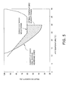
- relative humidity levels obtained by conversion from the individual target humidity levels (absolute humidity levels) set at different times as described above are included in the shaded area of the graph shown in FIG. 5 .
- the shaded area in the graph in FIG. 5 represents a range that is higher than the humidity at which the oral mucous membrane dries up and lower than the humidity at which mold forms.
- these individual target humidity levels (absolute humidity levels) fall within the range of absolute humidity levels converted from the range in FIG. 5 (relative humidity levels), whereby the indoor humidity is maintained in the range resulting from the conversion. Consequently, the user of a room, particularly when waking, can wake up comfortably without feeling thirsty and without feeling a lack of skin moisture or other uncomfortable sensations.
- the predetermined time period t1 is a pre-established time period, as is the predetermined time period t2.
- the time information outputted from the timer 8b is also used to determine whether or not the time period has reached the predetermined time period t1, similar to the target temperature setting unit 8c.
- the temperature control unit 8e controls the devices of the indoor unit 2 and the outdoor air-conditioning unit 5 so that the indoor temperature reaches the target temperature set by the target temperature setting unit 8c.
- the temperature control unit 8e controls the devices in the refrigerant circuit on the basis of the indoor temperature sensed by the indoor temperature thermistor 25 so that heated or cooled air is sent into the room to bring the indoor temperature to the first target temperature TM.
- the temperature control unit 8e controls the devices in the refrigerant circuit on the basis of the indoor temperature sensed by the indoor temperature thermistor 25 so that the indoor temperature reaches the target temperature individually set at different times by the target temperature setting unit 8c.
- the humidity control unit 8f controls the devices of the indoor unit 2, the outdoor air-conditioning unit 5 (specifically, the refrigerant circuit), and the air supply/humidification unit 4 so that the indoor humidity reaches the target humidity set by the target humidity setting unit 8d.
- the humidity control unit 8f controls the devices in the refrigerant circuit and the air supply/humidification unit 4 on the basis of the indoor humidity sensed by the indoor humidity sensor 26 so that humidified or dehumidified air is sent into the room to bring the indoor humidity to the first target humidity DM.
- the temperature control unit 8e controls the devices in the refrigerant circuit and the air supply/humidification unit 4 on the basis of the indoor humidity sensed by the indoor humidity sensor 26 so that the indoor humidity reaches the individual target humidity set at different times by the target humidity setting unit 8d.
- the humidity control unit 8f performs absolute humidity control because the set target humidity is an absolute humidity.
- the indoor humidity sensed by the indoor humidity sensor 26 is a relative humidity.
- the humidity control unit 8f uses the indoor temperature sensed by the indoor temperature thermistor 25 to convert the indoor humidity sensed by the indoor humidity sensor 26 into an absolute humidity, and controls so that the converted absolute humidity reaches the individual target humidity.
- the humidity control unit 8f performs absolute humidity control, thereby creating a more comfortable indoor humidity for the user.
- FIG. 6 is a flowchart showing the overall operational flow of the air conditioner 1.
- Step S1 Assume that the receive unit 21 in the indoor unit 2 of the air conditioner 1 receives a command to turn on the power source of the air conditioner 1 from a remote controller or the like (S1), and then that various operation initiation commands are received.
- Steps S2 to S4 In cases in which the operation initiation command received by the receive unit 21 of the indoor unit 2 is for the automatic operation mode (S2), the mode control unit 8a outputs a mode setting signal indicating a command to initiate the automatic operation mode to the timer 8b, the target temperature setting unit 8c, and the target humidity setting unit 8d.
- the target temperature setting unit 8c and the target humidity setting unit 8d set the indoor target temperature and target humidity to the first target temperature TM and the first target humidity DM, respectively (S3).
- the temperature control unit 8e and the humidity control unit 8f automatically control the indoor temperature and humidity (S4). Specifically, the temperature control unit 8e and the humidity control unit 8f control the respective devices in the refrigerant circuit and the air supply/humidification unit 4 so that the indoor temperature and humidity reach the first target temperature TM and the first target humidity DM.
- Steps S5 and 6 In cases in which the operation initiation command received by the receive unit 21 of the indoor unit 2 is for the rest operation mode (S5), the mode control unit 8a outputs a mode setting signal indicating a command to initiate the rest operation mode to the timer 8b, the target temperature setting unit 8c, and the target humidity setting unit 8d.
- the control unit 8 controls in the rest operation mode (S6). Control in the rest operation mode is described hereinafter.
- Steps S7 and 8 The operation initiation command received by the receive unit 21 of the indoor unit 2 may be an operation initiation command for, e.g., heating, cooling, or another operation (S7).
- the mode control unit 8a notifies the timer 8b, the target temperature setting unit 8c, and the target humidity setting unit 8d of this command.
- the control unit 8 controls the operation as instructed (S8).
- Step S9 In cases in which the receive unit 21 of the indoor unit 2 has received a command to turn off the power source of the air conditioner 1 from a remote controller or the like (S9), the air conditioner 1 stops operating. The air conditioner 1 will repeat the actions from step S2 onward until the receive unit 21 of the indoor unit 2 receives a command to turn the power source off.
- FIG. 7 is a flowchart describing control in the rest operation mode.
- Step S21 The timer 8b of the control unit 8 begins to output time information upon acquiring a mode setting signal indicating a command to initiate the rest operation mode from the mode control unit 8a.
- Step S22 The target temperature setting unit 8c sets the indoor target temperature (TM - 0.5) to 0.5 degrees less than the first target temperature TM, and the target humidity setting unit 8d sets the indoor target humidity (DM - DW) to be less than the first target humidity DM by the predetermined humidity DW.
- the temperature control unit 8e controls the devices in the refrigerant circuit so that the indoor temperature reaches the target temperature (TM - 0.5).
- the humidity control unit 8f converts the indoor humidity sensed by the indoor humidity sensor 26 into an absolute humidity, and controls the devices in the refrigerant circuit and the air supply/humidification unit 4 so that the converted absolute humidity reaches the target humidity (DM - DW).
- Step S23 The target temperature setting unit 8c lowers the target temperature by 0.5 degrees with every time interval "tdvdown" until the indoor target temperature reaches "TM - 2" degrees.
- the temperature control unit 8e controls the devices in the refrigerant circuit so that the indoor temperature reaches the individual target temperature set at different times by the target temperature setting unit 8c.
- Steps S24 and 25 At a certain time period, i.e., when the time information from the timer 8b reaches the predetermined time period t1 after the acquisition of a mode setting signal indicating a command to initiate the rest operation mode (S24), the target humidity setting unit 8d sets the target humidity to "DM + DC," which is higher than the first target humidity DM by a predetermined humidity DC (S25).
- the humidity control unit 8f converts the indoor humidity sensed by the indoor humidity sensor 26 into an absolute humidity and controls the devices in the refrigerant circuit and the air supply/humidification unit 4 so that the converted absolute humidity reaches the target humidity DM + DC.
- Steps S26 and 27 At a certain time period, i.e., when the time information from the timer 8b reaches the predetermined time period t2 after the acquisition of a mode setting signal indicating a command to initiate the rest operation mode (S26), the target temperature setting unit 8c raises the target temperature by 0.5 degrees with each time interval "tdvup" until the target temperature reaches the first target humidity DM (S27).
- the temperature control unit 8e controls the devices in the refrigerant circuit so that the indoor temperature reaches the individual target temperature set at different times by the target temperature setting unit 8c.
- Steps S28 and 29 When the time information from the timer 8b reaches the scheduled waking time (S28), the target temperature setting unit 8c sets the indoor target temperature to the first target temperature TM, and the target humidity setting unit 8d sets the indoor target humidity to the first target humidity DM (S29).
- the temperature control unit 8e controls so that the indoor temperature reaches the first target temperature TM
- the humidity control unit 8f controls so that the indoor humidity reaches the first target humidity DM.
- the mode control unit 8a presents the timer 8b, the target temperature setting unit 8c, and the target humidity setting unit 8d with an outputted mode setting signal for switching the operation mode to the automatic operation mode.
- the functional units in the control unit 8 are thereby caused to operate in the automatic mode.
- setting the rest operation mode causes the indoor target humidity to be set to a humidity "DM - DW", which is less by the predetermined humidity DW than the first target humidity DM maintained during the automatic operation mode or another regular mode, and the indoor humidity is controlled. Sweating is promoted and the user can sleep deeply because the indoor humidity is thereby brought to a lower level than in a regular mode when the user is falling asleep.
- the indoor target humidity is set to a humidity "DM + DC," which higher than the first target humidity DM by a predetermined humidity DC, and the indoor humidity is controlled.
- the indoor humidity is thereby brought to a higher humidity than in a regular mode when the user wakes up, and sweating in the user is therefore suppressed, as is skin or throat dryness.
- the air conditioner 1 controls the indoor temperature so that the indoor temperature decreases in accordance with the decrease in the user's core body temperature when the user is falling asleep, and also so that the lowered indoor temperature is then raised in accordance with the increase in the user's body temperature when the user wakes up. Specifically, when the rest operation mode is set, the air conditioner 1 controls not only the humidity but the temperature as well. The user can thereby be allowed to fall asleep and wake up more comfortably.
- the air conditioner 1 also sets the target humidity so as to be within a range ( FIG. 5 ) that is higher than the humidity at which the oral mucous membrane dries up and lower than the humidity at which mold forms.
- the room interior is thereby maintained at a comfortable humidity level both at the time when the user falls asleep and at the time when the user wakes up.
- the air conditioner 1 of the present embodiment uses absolute humidity as the target humidity and controls based on the absolute humidity, or the relative humidity in a manner equivalent to the absolute humidity, so that the indoor humidity reaches the target humidity.
- the room interior is thereby brought to a more comfortable humidity level for the user when the user falls asleep or wakes up.
- the air conditioner 1 may set the target humidity to "DM + DC" after the start of the rest operation mode.
- the target humidity setting unit 8d of the control unit 8 makes earlier the timing of increasing the target humidity in accordance with the changed scheduled waking time.
- the target temperature setting unit 8c also may change the range of reduction, the range of increase, the level of reduction, the timing of increase, and other factors of the target temperature in accordance with the changed scheduled waking time.
- the target humidity setting unit 8d of the control unit 8 makes later the timing of increasing the target humidity in accordance with the changed scheduled waking time.
- the target temperature setting unit 8c also may change the range of reduction, the range of increase, the level of reduction, the timing of increase, and other factors of the target temperature in accordance with the changed scheduled waking time.
- the air conditioner does not raise the target humidity while controlling for the target temperature to lower in steps, as shown in FIG 4 of the embodiment described above.
- the present invention has the effect of being able to promote comfortable sleep for the user, and the present invention can be used as an air conditioner.
Landscapes
- Engineering & Computer Science (AREA)
- Chemical & Material Sciences (AREA)
- Combustion & Propulsion (AREA)
- Mechanical Engineering (AREA)
- General Engineering & Computer Science (AREA)
- Signal Processing (AREA)
- Physics & Mathematics (AREA)
- Fuzzy Systems (AREA)
- Mathematical Physics (AREA)
- Air Conditioning Control Device (AREA)
Abstract
Description
- The present invention relates to an air conditioner, and particularly to an air conditioner having a regular mode and a sleep mode. The present invention also relates to an indoor humidity control method for controlling indoor humidity.
- Many modem air conditioners have various functions, such as a regular mode for making indoor temperature and humidity more comfortable, and a sleep mode for bedtime.
- Sleep mode is a function for conditioning indoor air so that a user can sleep comfortably. One particular example of an air conditioner having the sleep mode is an air conditioner for adjusting indoor temperature in accordance with a user's biological rhythms during sleep, such as the air conditioner disclosed in
patent document 1, for example. - Patent Document 1: Japanese Laid-open Patent Document No.
5-106899 - Examples of biological rhythms during sleep include those pertaining to temperature, such as the core body temperature decreasing when falling asleep and the body temperature returning to normal when awakening, as well as making it easier to fall asleep by sweating. Therefore, even if the temperature is adjusted in the same manner as with the air conditioner of
patent document 1, the user has trouble falling asleep in cases of high indoor humidity because it is difficult for sweating to occur. The lower the indoor humidity when the user awakens, the thirstier the user is or the less moisture there is in the user's skin. During the winter season when the air is dry, these phenomena are particularly prominent. - In view of this, the present invention provides an air conditioner and a humidity control method whereby the indoor air can be adjusted so that a user indoors can sleep comfortably when a sleep mode has been set by the user.
- An air conditioner according to a first aspect of the present invention is an air conditioner having a regular mode and a sleep mode. The air conditioner comprises a humidity adjustment unit and a humidity control unit. The humidity adjustment unit humidifies or dehumidifies air and supplies the air into a room. The humidity control unit controls the humidity adjustment unit during the regular mode so that the indoor humidity reaches a first target humidity. The humidity control unit also controls the humidity adjustment unit during the sleep mode so that the indoor humidity reaches a second target humidity, which is lower than the first target humidity.
- For example, a user intending to sleep in a room provided with this air conditioner may set the air conditioner to the sleep mode. In this case, the air conditioner sets the indoor target humidity to be lower than during the regular mode. When the user is falling asleep, the indoor humidity is thereby set to a lower humidity than during the regular mode. Sweating is therefore promoted, and the user can sleep deeply.
- An air conditioner according to a second aspect is the air conditioner according to the first aspect, wherein the second target humidity is within a range that is higher than the humidity at which the oral mucous membrane dries up and lower than the humidity at which mold forms.
- The room interior is thereby maintained at a comfortable humidity level for a user falling asleep in cases in which the air conditioner has been set to the sleep mode.
- An air conditioner according to a third aspect is the air conditioner according to the first or second aspect, wherein the second target humidity is an absolute humidity.
- Conventional air conditioners have controlled based on relative humidity. However, the air conditioner according to the third aspect uses absolute humidity as the target humidity and controls in accordance with the absolute humidity, or the relative humidity in a manner equivalent to the absolute humidity, so that the indoor humidity reaches the target humidity. The room interior thereby reaches a comfortable humidity level for a user falling asleep.
- An air conditioner according to a fourth aspect is the air conditioner according to any of the first through third aspects, further comprising a temperature adjustment unit and a temperature control unit. The temperature adjustment unit cools or heats air to adjust the indoor temperature. The temperature control unit controls the temperature adjustment unit during the sleep mode so that the indoor temperature reaches a second target temperature, which is below a first target temperature set during the regular mode.
- The air conditioner further controls the temperature so that the indoor temperature decreases in accordance with the decrease in a user's core body temperature when the user is sleeping, for example. Thus, the user can sleep deeply due to the temperature being controlled in addition to the humidity when the user is falling asleep.
- An air conditioner according to a fifth aspect is an air conditioner having a regular mode and a sleep mode. The air conditioner comprises a humidity adjustment unit, a command receive unit, and a humidity control unit. The humidity adjustment unit humidifies or dehumidifies air and supplies the air into a room. The command receive unit receives operation initiation commands for the regular mode or the sleep mode. The humidity control unit controls the humidity adjustment unit so that the indoor humidity reaches a third target humidity when the command receive unit has received a command to initiate the regular mode operation. The humidity control unit also controls the humidity adjustment unit so that the indoor humidity reaches a fourth target humidity, which is higher than the third target humidity, when a predetermined time period has passed after the command receive unit received a command to initiate the sleep mode operation.
- For example, a user intending to sleep in a room provided with this air conditioner may set the air conditioner to the sleep mode. In this case, the air conditioner adjusts the indoor target humidity to be higher than during the regular mode when a predetermined time period has passed after the sleep mode operation was initiated. The indoor humidity is thereby set to a higher humidity than during the regular mode when the user wakes up. Consequently, sweating in the user is suppressed, as is skin or throat dryness.
- An air conditioner according to a sixth aspect is the air conditioner according to the fifth aspect, wherein the fourth target humidity is within a range that is higher than the humidity at which the oral mucous membrane dries up and lower than the humidity at which mold forms.
- The room interior is thereby maintained at a humidity at which an appropriate amount of moisture is contained in the user's skin or throat when the user wakes up.
- An air conditioner according to a seventh aspect is the air conditioner according to the fifth or sixth aspect, wherein the fourth target humidity is an absolute humidity.
- Conventional air conditioners have controlled based on relative humidity. However, the air conditioner according to the seventh aspect uses absolute humidity as the target humidity and controls in accordance with the absolute humidity, or the relative humidity in a manner equivalent to the absolute humidity, so that the indoor humidity reaches the target humidity. The user can thereby be woken up with a more appropriate amount of moisture in the skin and throat.
- An air conditioner according to an eighth aspect is the air conditioner according to any of the fifth through seventh aspects, further comprising a temperature adjustment unit and a temperature control unit. The temperature adjustment unit heats or cools air to adjust the indoor temperature. The temperature control unit controls the temperature adjustment unit so that the indoor temperature reaches a fourth target temperature, which is below a third target temperature set during the regular mode, when the command receive unit has received a command to initiate the sleep mode operation. The temperature control unit also controls the temperature adjustment unit so that the indoor temperature reaches the third target temperature when at least the predetermined time period has passed after the command receive unit received the command to initiate the sleep mode operation.
- The air conditioner further controls the temperature so that the lowered indoor temperature is raised in accordance with the increase in the user's body temperature when the user wakes up, for example. Thus, the user can be woken up more comfortably by controlling the temperature in addition to humidity during waking.
- A humidity control method according to a ninth aspect is a method for controlling indoor humidity so that the indoor humidity during a regular mode reaches a fifth target humidity. The humidity control method comprises
steps 1 through 3.Step 1 is a step for receiving a command to initiate a sleep mode operation.Step 2 is a step for dehumidifying or humidifying air and supplying the air into a room so that the indoor humidity reaches a sixth target humidity, which is lower than the fifth target humidity.Step 3 is a step for humidifying air and supplying the air into the room so that the indoor humidity reaches a seventh target humidity, which is higher than the fifth target humidity, when a predetermined time period has passed after the operation initiation command was received. - Sweating is thereby promoted when the user is falling asleep because the indoor humidity is lower than the humidity during the regular mode. Consequently, the user can sleep deeply. The indoor humidity is thereby higher than the humidity during the regular mode when the user wakes up, and sweating in the user is therefore suppressed, as is skin and throat dryness.
- With the air conditioner according to the first aspect, sweating is promoted when the user is falling asleep, and the user can sleep deeply.
- With the air conditioner according to the second aspect, the room interior is maintained at a humidity at which a user can fall asleep comfortably.
- With the air conditioner according to the third aspect, the room interior reaches a more comfortable humidity when the user is falling asleep.
- With the air conditioner according to the fourth aspect, the user can sleep more deeply because the temperature is controlled in addition to the humidity when the user is falling asleep.
- With the air conditioner according to the fifth aspect, sweating in the user is suppressed when the user wakes up, as is skin and throat dryness.
- With the air conditioner according to the sixth aspect, the room interior is maintained at a humidity at which an appropriate amount of moisture is contained in the user's skin or throat when the user wakes up.
- With the air conditioner according to the seventh aspect, the user can wake up with a more appropriate amount of moisture in the skin or throat.
- With the air conditioner according to the eighth aspect, the user can be woken up more comfortably by controlling the temperature in addition to humidity during waking.
- With the humidity control method according to the ninth aspect, sweating is promoted when the user is falling asleep, and the user can sleep deeply. Sweating in the user is also suppressed when the user wakes up, as is skin or throat dryness.
-
-
FIG 1 is an external view of the air conditioner according to the present embodiment. -
FIG 2 is a diagram showing the configuration of the refrigerant circuit and air supply/humidification unit according to the present embodiment, and the air flow therein. -
FIG. 3 is a diagram schematically depicting the connections between the control unit of the air conditioner according to the present embodiment and the peripheral devices of the control unit. -
FIG. 4 is a diagram depicting the indoor target temperature and target humidity over time, as controlled by the air conditioner according to the present embodiment. -
FIG 5 is a diagram showing the range in which the target temperature and target humidity are set. -
FIG 6 is a flowchart showing the overall operational flow of the air conditioner according to the present embodiment; and -
FIG 7 is the sub-routine of control in the rest operation mode of the air conditioner according to the present embodiment. -
- 1
- Air conditioner
- 2
- Indoor unit
- 3
- Outdoor unit
- 4
- Air supply/humidification unit
- 5
- Outdoor air-conditioning unit
- 6
- Refrigerant supply tube
- 7
- Air supply tube
- 8
- Control unit
- 8a
- Mode control unit
- 8b
- Timer
- 8c
- Target temperature setting unit
- 8d
- Target humidity setting unit
- 8e
- Temperature control unit
- 8f
- Humidity control unit
- 21
- Receive unit
- 25
- Indoor temperature thermistor
- 26
- Indoor humidity sensor
-
FIG. 1 is an external view of an air conditioner according to an embodiment of the present invention. Thisair conditioner 1 is divided into anindoor unit 2 mounted on an indoor wall surface or the like, and anoutdoor unit 3 installed outdoors. In addition to indoor cooling and heating operations, a dehumidifying operation, and a humidifying operation, theair conditioner 1 has an automatic operating mode (equivalent to a regular mode), a rest operating mode (equivalent to a sleep mode), and other functions. - The
indoor unit 2 is provided with a receiveunit 21, anindoor temperature thermistor 25, anindoor humidity sensor 26, and other components, as shown inFIGS. 1 and3 . The receiveunit 21 is provided so as to be capable of receiving commands sent from a remote controller, for example, to initiate the automatic operating mode, the rest operating mode, and other various functions. Theindoor temperature thermistor 25 and theindoor humidity sensor 26 sense the indoor temperature and humidity, respectively. Furthermore, the interior of theindoor unit 2 also houses anindoor heat exchanger 22, anindoor fan motor 24, and other components, but these are described hereinafter. - The
outdoor unit 3 comprises an outdoor air-conditioning unit 5, which an outdoor heat exchanger 54 (described hereinafter), anoutdoor temperature thermistor 63 for sensing the outdoor temperature, and other components are provided therein; and an air supply/humidification unit 4 for supplying air drawn in from the outside into a room, either directly or after humidification. - The heat exchangers and
refrigerant supply tubes indoor unit 2 and theoutdoor unit 3 is anair supply tube 7 used when air sent from the air supply/humidification unit 4 is supplied toward theindoor unit 2. - Next, the refrigerant circuit used by the
air conditioner 1 of the present embodiment will be described together with the internal configurations of theindoor unit 2 and theoutdoor unit 3.FIG. 2 is a schematic diagram of the refrigerant circuit used by theair conditioner 1. - The
indoor heat exchanger 22, across-flow fan 23, and theindoor fan motor 24 are provided in theindoor unit 2. Theindoor heat exchanger 22 is composed of a heat exchanger tube which folds back multiple times at both longitudinal ends, and a plurality of fms through which the heat exchanger tube passes; and theindoor heat exchanger 22 exchanges heat with the air with which it comes in contact. For example, theindoor heat exchanger 22 functions as an evaporator during the cooling operation or during a drying operation. Consequently, when indoor air comes in contact with theindoor heat exchanger 22 functioning as an evaporator, the moisture in the air condenses into water droplets and drips down into a drain pan (not shown) provided underneath theindoor heat exchanger 22. The temperature and humidity in the indoor air thereby decrease. During the heating operation, indoor air coming in contact with theindoor heat exchanger 22 is warmed because theindoor heat exchanger 22 functions as a condenser. - The
cross-flow fan 23 is configured into a cylindrical shape with numerous blades provided around the peripheral surface, and thecross-flow fan 23 generates an air flow in a direction intersecting with the rotational axis. Thecross-flow fan 23 causes indoor air to be drawn into theindoor unit 2, and also blows out air into the room after the air has exchanged heat with theindoor heat exchanger 22. The purpose of theindoor fan motor 24 is to rotatably drive thecross-flow fan 23. - Provided in the interior of the outdoor air-
conditioning unit 5 are acompressor 51, a four-way switching valve 52 connected at the discharge side of thecompressor 51, anaccumulator 53 connected at the intake side of thecompressor 51, theoutdoor heat exchanger 54 connected to the four-way switching valve 52, and an motor-operatedvalve 55 connected to theoutdoor heat exchanger 54. The motor-operatedvalve 55 is connected to therefrigerant supply tube 6a via afilter 56 and aliquid shutoff valve 57, and is also connected to one end of theindoor heat exchanger 22 via therefrigerant supply tube 6a. The four-way switching valve 52 is connected to therefrigerant supply tube 6b via agas shutoff valve 58, and is also connected to the other end of theindoor heat exchanger 22 via therefrigerant supply tube 6b. The four-way switching valve 52 switches the flow of the refrigerant between cooling and heating operation. - A
propeller fan 59 is provided inside the outdoor air-conditioning unit 5. The purpose of thepropeller fan 59 is to discharge air to the exterior after the air has undergone heat exchange in theoutdoor heat exchanger 54, and thepropeller fan 59 is rotatably driven by anoutdoor fan motor 60. - Next, the configuration of the air supply/
humidification unit 4 will be described usingFIG. 2 . The air supply/humidification unit 4 includes a moisture- adsorbing/humidifyingrotor 41, aheater 43, aradial fan assembly 44, and anadsorption fan 45. - The moisture-adsorbing/humidifying
rotor 41 is a ceramic rotor with a honeycomb structure having a substantially circular shape, wherein air can easily pass through. The moisture-adsorbing/humidifyingrotor 41 is rotatably driven by arotor drive motor 42. Zeolite, silica gel, alumina, or another adsorbent is supported on the moisture- adsorbing/humidifyingrotor 41. The zeolite adsorbent is capable of adsorbing moisture in the air with which it comes in contact, and the adsorbent has the property of being caused to desorb moisture by heating. - During the humidifying operation, the
heater 43 heats air taken in from outdoors and sent to the moisture-adsorbing/humidifyingrotor 41. - The
radial fan 44 is disposed to the side of the moisture-adsorbing/humidifyingrotor 41 and is driven by aradial fan motor 44a. Theradial fan 44 creates an air flow (A1 inFIG. 2 ) that moves from anair supply port 40a for guiding in air from outdoors, through the moisture-adsorbing/humidifyingrotor 41, and into the room. Theradial fan 44 has the role of sending air from outdoors to theindoor unit 2 via theair supply tube 7. - The
adsorption fan 45 is rotatably driven by anadsorption fan motor 46. Theadsorption fan 45 creates an air flow (A2 inFIG. 2 ) so that air taken in from an adsorptionair intake port 40b is discharged outdoors via an adsorption air suction port 40c. The adsorptionair intake port 40b is an opening for the passage of air taken in from outside the air supply/humidification unit 4 in order to allow moisture to be adsorbed on the moisture- adsorbing/humidifyingrotor 41, and the adsorption air suction port 40c is an opening for discharging air outdoors after the moisture in the air has been adsorbed by the moisture- adsorbing/humidifyingrotor 41. - During humidification with this type of air supply/
humidification unit 4, theheater 43 turns on, the air taken in from theair supply port 40a is heated by the heater, and the air containing the moisture desorbed from the moisture-adsorbing/humidifyingrotor 41 is sent to theair supply tube 7. When air is supplied in the absence of humidification, theheater 43 turns off, and the air taken in from theair supply port 40a is sent directly to theair supply tube 7. - Next, a
control unit 8 for controlling theair conditioner 1 will be described usingFIG. 3 . Thecontrol unit 8 is a microcomputer composed of a CPU and memory, and is separated into electrical equipment boxes or the like disposed in theindoor unit 2 and in theoutdoor unit 3. Thecontrol unit 8 is connected to the devices of theindoor unit 2 andoutdoor unit 3, and thecontrol unit 8 controls the devices to which it is connected. Particularly, thecontrol unit 8 according to the present embodiment controls the indoor humidity and temperature in accordance with human biological rhythms when the receiveunit 21 of theindoor unit 2 has received a command to initiate the rest operation mode. In order to perform such an action, thecontrol unit 8 functions as amode control unit 8a, atimer 8b, a targettemperature setting unit 8c, a targethumidity setting unit 8d, atemperature control unit 8e, and ahumidity control unit 8f. The functions are described hereinbelow. - When the receive
unit 21 of theindoor unit 2 receives various operation commands from a remote controller or the like, themode control unit 8a controls the operation mode of theair conditioner 1 in accordance with the operation command. Specifically, in cases in which the receiveunit 21 has received a command to initiate the automatic operation mode, a command to initiate the rest operation mode, or another command, themode control unit 8a outputs a mode setting signal indicating the command to thetimer 8b, the targettemperature setting unit 8c, and the targethumidity setting unit 8d. In the present embodiment, the mode setting signal indicating the command to initiate the rest operation mode is assumed to include a scheduled waking time set by the user via the remote controller. - The
timer 8b initiates the output of time information upon acquiring a mode setting signal from themode control unit 8a. The time information outputted from thetimer 8b is received by the targettemperature setting unit 8c and the targethumidity setting unit 8d. - The target
temperature setting unit 8c sets an indoor target temperature on the basis of the mode setting signal acquired from themode control unit 8a. Specifically, the targettemperature setting unit 8c sets the indoor target temperature to a first target temperature TM in cases in which the targettemperature setting unit 8c has acquired a mode setting signal indicating a command to initiate the automatic operation mode. The targettemperature setting unit 8c sets the target temperature in accordance with human biological rhythms in cases in which the targettemperature setting unit 8c has acquired a mode setting signal indicating a command to initiate the rest operation mode. -
FIG. 4 is used to describe the manner in which the targettemperature setting unit 8c sets the target temperature in cases in which the targettemperature setting unit 8c has acquired a mode setting signal indicating a command to initiate the rest operation mode. Upon acquiring a mode setting signal indicating a command to initiate the rest operation mode, the targettemperature setting unit 8c first sets the indoor target temperature to a temperature 0.5 degrees less than the first target temperature TM, and continues to lower the target temperature by 0.5-degree at intervals of a time period "tdvdown," as shown inFIG. 4 . The targettemperature setting unit 8c repeats this action until the indoor target temperature reaches a temperature approximately 2 degrees less than the first target temperature TM. For this action, the time period "tdvdown" is adjusted so that the target temperature promptly reaches a temperature approximately 2 degrees less than the first target temperature TM at, e.g., 3 hours after the rest operation mode was initiated. - When a predetermined time period t2 elapses after the acquisition of the mode setting signal indicating a command to initiate the rest operation mode, the target
temperature setting unit 8c first raises the indoor target temperature by 0.5 degrees. When a time period "tdvup" elapses after the indoor target temperature has been raised by 0.5 degrees, the targettemperature setting unit 8c raises the target temperature another 0.5 degrees. The targettemperature setting unit 8c repeats this action until the target temperature reaches the original first target temperature TM. For this action, the time period "tdvup" is adjusted so that the target temperature promptly reaches the first target temperature TM at, e.g., the scheduled waking time. - To start raising the target temperature after the passage of the predetermined time period t2, the target
temperature setting unit 8c calculates the time remaining in the rest operation mode from the user's scheduled waking time and the current time. The targettemperature setting unit 8c may perform the aforementioned action in cases in which the remaining time is less than a predetermined time period "tr." The predetermined time period "tr" can be set to 1 hour, for example. The predetermined time period t2 is assumed to be a pre-established time period. - It is assumed that the time information outputted from the
timer 8b is used to determine whether or not the time period has reached the predetermined time period t2. - The target
humidity setting unit 8d sets the indoor target humidity at an absolute humidity level on the basis of the mode setting signal acquired from themode control unit 8a. Specifically, the targethumidity setting unit 8d sets the indoor target humidity to a first target humidity DM in cases in which a mode setting signal indicating a command to initiate the automatic operation mode has been acquired. The targethumidity setting unit 8d also sets the target humidity in accordance with sleeping, waking, and other user actions, in cases in which a mode setting signal indicating a command to initiate the rest operation mode has been acquired. -
FIG. 4 is used to describe the manner in which the targethumidity setting unit 8d sets the target humidity in cases in which the targethumidity setting unit 8d has acquired a mode setting signal indicating a command to initiate the rest operation mode, similar to the targettemperature setting unit 8c. Upon acquiring a mode setting signal indicating a command to initiate the rest operation mode, the targethumidity setting unit 8d sets the indoor target humidity to a humidity (DM - DW) less than the first target humidity DM by a predetermined humidity DW, as shown inFIG. 4 . When a predetermined time period t1 elapses after the acquisition of the mode setting signal indicating a command to initiate the rest operation mode, the targethumidity setting unit 8d then sets the indoor target humidity to a humidity (DM + DC) higher than the first target humidity DM by a predetermined humidity DC. When the rest operation mode ends and automatic operation or another regular mode is restored, the targethumidity setting unit 8d sets the target humidity to the first target humidity DM. - The predetermined humidity levels DW, DC are empirically established values. In the present embodiment, relative humidity levels obtained by conversion from the individual target humidity levels (absolute humidity levels) set at different times as described above are included in the shaded area of the graph shown in
FIG. 5 . The shaded area in the graph inFIG. 5 represents a range that is higher than the humidity at which the oral mucous membrane dries up and lower than the humidity at which mold forms. Thus, these individual target humidity levels (absolute humidity levels) fall within the range of absolute humidity levels converted from the range inFIG. 5 (relative humidity levels), whereby the indoor humidity is maintained in the range resulting from the conversion. Consequently, the user of a room, particularly when waking, can wake up comfortably without feeling thirsty and without feeling a lack of skin moisture or other uncomfortable sensations. - The predetermined time period t1 is a pre-established time period, as is the predetermined time period t2.
- The time information outputted from the
timer 8b is also used to determine whether or not the time period has reached the predetermined time period t1, similar to the targettemperature setting unit 8c. - The
temperature control unit 8e controls the devices of theindoor unit 2 and the outdoor air-conditioning unit 5 so that the indoor temperature reaches the target temperature set by the targettemperature setting unit 8c. - Specifically, during the automatic operation mode, the
temperature control unit 8e controls the devices in the refrigerant circuit on the basis of the indoor temperature sensed by theindoor temperature thermistor 25 so that heated or cooled air is sent into the room to bring the indoor temperature to the first target temperature TM. - In the rest operation mode, the
temperature control unit 8e controls the devices in the refrigerant circuit on the basis of the indoor temperature sensed by theindoor temperature thermistor 25 so that the indoor temperature reaches the target temperature individually set at different times by the targettemperature setting unit 8c. - The
humidity control unit 8f controls the devices of theindoor unit 2, the outdoor air-conditioning unit 5 (specifically, the refrigerant circuit), and the air supply/humidification unit 4 so that the indoor humidity reaches the target humidity set by the targethumidity setting unit 8d. - For example, during a normal operating mode, the
humidity control unit 8f controls the devices in the refrigerant circuit and the air supply/humidification unit 4 on the basis of the indoor humidity sensed by theindoor humidity sensor 26 so that humidified or dehumidified air is sent into the room to bring the indoor humidity to the first target humidity DM. - During the rest operation mode, the
temperature control unit 8e controls the devices in the refrigerant circuit and the air supply/humidification unit 4 on the basis of the indoor humidity sensed by theindoor humidity sensor 26 so that the indoor humidity reaches the individual target humidity set at different times by the targethumidity setting unit 8d. - The
humidity control unit 8f according to the present embodiment performs absolute humidity control because the set target humidity is an absolute humidity. On the other hand, the indoor humidity sensed by theindoor humidity sensor 26 is a relative humidity. In view of this, thehumidity control unit 8f uses the indoor temperature sensed by theindoor temperature thermistor 25 to convert the indoor humidity sensed by theindoor humidity sensor 26 into an absolute humidity, and controls so that the converted absolute humidity reaches the individual target humidity. Thus, thehumidity control unit 8f performs absolute humidity control, thereby creating a more comfortable indoor humidity for the user. - Next, the operation of the
air conditioner 1 will be described.FIG. 6 is a flowchart showing the overall operational flow of theair conditioner 1. - Step S1: Assume that the receive
unit 21 in theindoor unit 2 of theair conditioner 1 receives a command to turn on the power source of theair conditioner 1 from a remote controller or the like (S1), and then that various operation initiation commands are received. - Steps S2 to S4: In cases in which the operation initiation command received by the receive
unit 21 of theindoor unit 2 is for the automatic operation mode (S2), themode control unit 8a outputs a mode setting signal indicating a command to initiate the automatic operation mode to thetimer 8b, the targettemperature setting unit 8c, and the targethumidity setting unit 8d. The targettemperature setting unit 8c and the targethumidity setting unit 8d set the indoor target temperature and target humidity to the first target temperature TM and the first target humidity DM, respectively (S3). Thetemperature control unit 8e and thehumidity control unit 8f automatically control the indoor temperature and humidity (S4). Specifically, thetemperature control unit 8e and thehumidity control unit 8f control the respective devices in the refrigerant circuit and the air supply/humidification unit 4 so that the indoor temperature and humidity reach the first target temperature TM and the first target humidity DM. - Steps S5 and 6: In cases in which the operation initiation command received by the receive
unit 21 of theindoor unit 2 is for the rest operation mode (S5), themode control unit 8a outputs a mode setting signal indicating a command to initiate the rest operation mode to thetimer 8b, the targettemperature setting unit 8c, and the targethumidity setting unit 8d. Thecontrol unit 8 controls in the rest operation mode (S6). Control in the rest operation mode is described hereinafter. - Steps S7 and 8: The operation initiation command received by the receive
unit 21 of theindoor unit 2 may be an operation initiation command for, e.g., heating, cooling, or another operation (S7). In such cases, themode control unit 8a notifies thetimer 8b, the targettemperature setting unit 8c, and the targethumidity setting unit 8d of this command. Thecontrol unit 8 controls the operation as instructed (S8). - Step S9: In cases in which the receive
unit 21 of theindoor unit 2 has received a command to turn off the power source of theair conditioner 1 from a remote controller or the like (S9), theair conditioner 1 stops operating. Theair conditioner 1 will repeat the actions from step S2 onward until the receiveunit 21 of theindoor unit 2 receives a command to turn the power source off. -
FIG. 7 is a flowchart describing control in the rest operation mode. - Step S21: The
timer 8b of thecontrol unit 8 begins to output time information upon acquiring a mode setting signal indicating a command to initiate the rest operation mode from themode control unit 8a. - Step S22: The target
temperature setting unit 8c sets the indoor target temperature (TM - 0.5) to 0.5 degrees less than the first target temperature TM, and the targethumidity setting unit 8d sets the indoor target humidity (DM - DW) to be less than the first target humidity DM by the predetermined humidity DW. Thetemperature control unit 8e controls the devices in the refrigerant circuit so that the indoor temperature reaches the target temperature (TM - 0.5). Thehumidity control unit 8f converts the indoor humidity sensed by theindoor humidity sensor 26 into an absolute humidity, and controls the devices in the refrigerant circuit and the air supply/humidification unit 4 so that the converted absolute humidity reaches the target humidity (DM - DW). - Step S23: The target
temperature setting unit 8c lowers the target temperature by 0.5 degrees with every time interval "tdvdown" until the indoor target temperature reaches "TM - 2" degrees. Thetemperature control unit 8e controls the devices in the refrigerant circuit so that the indoor temperature reaches the individual target temperature set at different times by the targettemperature setting unit 8c. - Steps S24 and 25: At a certain time period, i.e., when the time information from the
timer 8b reaches the predetermined time period t1 after the acquisition of a mode setting signal indicating a command to initiate the rest operation mode (S24), the targethumidity setting unit 8d sets the target humidity to "DM + DC," which is higher than the first target humidity DM by a predetermined humidity DC (S25). Thehumidity control unit 8f converts the indoor humidity sensed by theindoor humidity sensor 26 into an absolute humidity and controls the devices in the refrigerant circuit and the air supply/humidification unit 4 so that the converted absolute humidity reaches the target humidity DM + DC. - Steps S26 and 27: At a certain time period, i.e., when the time information from the
timer 8b reaches the predetermined time period t2 after the acquisition of a mode setting signal indicating a command to initiate the rest operation mode (S26), the targettemperature setting unit 8c raises the target temperature by 0.5 degrees with each time interval "tdvup" until the target temperature reaches the first target humidity DM (S27). Thetemperature control unit 8e controls the devices in the refrigerant circuit so that the indoor temperature reaches the individual target temperature set at different times by the targettemperature setting unit 8c. - Steps S28 and 29: When the time information from the
timer 8b reaches the scheduled waking time (S28), the targettemperature setting unit 8c sets the indoor target temperature to the first target temperature TM, and the targethumidity setting unit 8d sets the indoor target humidity to the first target humidity DM (S29). Thetemperature control unit 8e controls so that the indoor temperature reaches the first target temperature TM, and thehumidity control unit 8f controls so that the indoor humidity reaches the first target humidity DM. Themode control unit 8a presents thetimer 8b, the targettemperature setting unit 8c, and the targethumidity setting unit 8d with an outputted mode setting signal for switching the operation mode to the automatic operation mode. The functional units in thecontrol unit 8 are thereby caused to operate in the automatic mode. - In the
air conditioner 1 of the present embodiment, setting the rest operation mode causes the indoor target humidity to be set to a humidity "DM - DW", which is less by the predetermined humidity DW than the first target humidity DM maintained during the automatic operation mode or another regular mode, and the indoor humidity is controlled. Sweating is promoted and the user can sleep deeply because the indoor humidity is thereby brought to a lower level than in a regular mode when the user is falling asleep. - In the
air conditioner 1, when the predetermined time period t1 elapses after the initiation of the rest operation mode, the indoor target humidity is set to a humidity "DM + DC," which higher than the first target humidity DM by a predetermined humidity DC, and the indoor humidity is controlled. The indoor humidity is thereby brought to a higher humidity than in a regular mode when the user wakes up, and sweating in the user is therefore suppressed, as is skin or throat dryness. - Furthermore, the
air conditioner 1 controls the indoor temperature so that the indoor temperature decreases in accordance with the decrease in the user's core body temperature when the user is falling asleep, and also so that the lowered indoor temperature is then raised in accordance with the increase in the user's body temperature when the user wakes up. Specifically, when the rest operation mode is set, theair conditioner 1 controls not only the humidity but the temperature as well. The user can thereby be allowed to fall asleep and wake up more comfortably. - The
air conditioner 1 also sets the target humidity so as to be within a range (FIG. 5 ) that is higher than the humidity at which the oral mucous membrane dries up and lower than the humidity at which mold forms. The room interior is thereby maintained at a comfortable humidity level both at the time when the user falls asleep and at the time when the user wakes up. - Conventional air conditioners control based on relative humidity levels. However, the
air conditioner 1 of the present embodiment uses absolute humidity as the target humidity and controls based on the absolute humidity, or the relative humidity in a manner equivalent to the absolute humidity, so that the indoor humidity reaches the target humidity. The room interior is thereby brought to a more comfortable humidity level for the user when the user falls asleep or wakes up. - An embodiment of the present invention was described above, but the present invention is not limited to the above-described embodiment, and various modifications are possible within a range that does not deviate from the scope of the invention.
- (a) In the embodiment described above, a case was described in which the
air conditioner 1 operated in a rest mode when instructed to initiate the rest operation mode from a remote controller, but the air conditioner may operate in the rest mode as long as other additional conditions are met. An example of another condition is, e.g., a case in which the time from the start of the rest operation mode to the scheduled waking time is three hours or more, for example. - In a case in which the time from the start of the rest operation mode to the scheduled waking time is 3 hours or more but is less than the interval from the end of the predetermined time period t1 to the scheduled waking time (trh in
FIG. 5 ), theair conditioner 1 may set the target humidity to "DM + DC" after the start of the rest operation mode. - (b) When the
air conditioner 1 is operating in the rest mode, theair conditioner 1 can control corresponding to a changed scheduled waking time in cases in which the scheduled waking time has been changed by the user, for example. - For example, in cases in which the scheduled waking time is changed to be earlier than the originally set time, the target
humidity setting unit 8d of thecontrol unit 8 makes earlier the timing of increasing the target humidity in accordance with the changed scheduled waking time. The targettemperature setting unit 8c also may change the range of reduction, the range of increase, the level of reduction, the timing of increase, and other factors of the target temperature in accordance with the changed scheduled waking time. - In cases in which the scheduled waking time is changed to be later than the originally set time, the target
humidity setting unit 8d of thecontrol unit 8 makes later the timing of increasing the target humidity in accordance with the changed scheduled waking time. The targettemperature setting unit 8c also may change the range of reduction, the range of increase, the level of reduction, the timing of increase, and other factors of the target temperature in accordance with the changed scheduled waking time. - (c) In the embodiment described above, a case was described in which the
air conditioner 1 ended the operation in the rest mode at the scheduled waking time set by the user, but the operation in the rest mode can be ended with other conditions. An example of another condition is a case in which a "stop" command is received during the rest operation. In such cases, theair conditioner 1 can switch to the operation in the automatic mode, for example. - (d) The
air conditioner 1 according to the embodiment described above no longer operates in the rest mode and returns the target temperature and humidity respectively to the normal target temperature and target humidity when the time reaches the scheduled waking time set by the user, but the air conditioner is not limited to this option alone. The air conditioner may also change the target temperature and humidity to a particular stored target temperature and target humidity (e.g., an environment suitable for the activity) after the scheduled waking time has passed. - (e) In the embodiment described above, the target temperature was lowered by approximately 0.5°C for a user who was falling asleep, and the target temperature was raised by approximately 0.5°C increments as the time approached the scheduled waking time, but the numerical values are not limited to these options alone. In the embodiment described above, the time intervals at which the target temperature was varied were uniform, but the time intervals need not be uniform. The air conditioner preferably controls so that the target temperature is lowered by a more accurate amount when the user is falling asleep than during normal times, and also so that the target temperature is raised by an appropriate amount when the user is waking from the lowered temperature maintained when the user was falling asleep. The air conditioner is not limited to controlling so that the operation mode maintained when the user is waking is the same as the automatic operation mode or another regular mode.
- The air conditioner does not raise the target humidity while controlling for the target temperature to lower in steps, as shown in
FIG 4 of the embodiment described above. - (f) In the embodiment described above, a separated-
type air conditioner 1 was described as an example, but the air conditioner is not limited to this option alone. The air conditioner according to the present invention can be applied to, e.g., an air conditioner embedded in a ceiling or the like, or other types of air conditioners. - The present invention has the effect of being able to promote comfortable sleep for the user, and the present invention can be used as an air conditioner.
Claims (9)
- An air conditioner (1) having a regular mode and a sleep mode, the air conditioner (1) comprising:a humidity adjustment unit (2, 4, 5) for humidifying or dehumidifying air and supplying the air into a room; anda humidity control unit (8f) for controlling the humidity adjustment unit (2, 4, 5) during the regular mode so that the indoor humidity reaches a first target humidity, and for controlling the humidity adjustment unit (2, 4, 5) during the sleep mode so that the indoor humidity reaches a second target humidity, which is lower than the first target humidity.
- The air conditioner (1) according to claim 1, wherein the second target humidity is within a range that is higher than the humidity at which the oral mucous membrane dries up and lower than the humidity at which mold forms.
- The air conditioner (1) according to claim 1 or 2, wherein the second target humidity is an absolute humidity.
- The air conditioner (1) according to any of claims 1 through 3, further comprising:a temperature adjustment unit (2, 5) for cooling or heating air to adjust the indoor temperature; anda temperature control unit (8e) for controlling the temperature adjustment unit (2, 5) during the sleep mode so that the indoor temperature reaches a second target temperature, which is below a first target temperature set during the regular mode.
- An air conditioner (1) having a regular mode and a sleep mode, the air conditioner (1) comprising:a humidity adjustment unit (2, 4, 5) for humidifying or dehumidifying air and supplying the air into a room;a command receive unit (21) capable of receiving operation initiation commands for the regular mode or the sleep mode; anda humidity control unit (8f) for controlling the humidity adjustment unit (2, 4, 5) so that the indoor humidity reaches a third target humidity when the command receive unit (21) has received a command to initiate the regular mode operation, and for controlling the humidity adjustment unit (2, 4, 5) so that the indoor humidity reaches a fourth target humidity, which is higher than the third target humidity, when a predetermined time period has passed after the command receive unit (21) received a command to initiate the sleep mode operation.
- The air conditioner (1) according to claim 5, wherein the fourth target humidity is within a range that is higher than the humidity at which the oral mucous membrane dries up and lower than the humidity at which mold forms.
- The air conditioner (1) according to claim 5 or 6, wherein the fourth target humidity is an absolute humidity.
- The air conditioner (1) according to any of claims 5 through 7, further comprising:a temperature adjustment unit (2, 5) for cooling or heating air to adjust the indoor temperature; anda temperature control unit (8e) for controlling the temperature adjustment unit (2, 5) so that the indoor temperature reaches a fourth target temperature, which is below a third target temperature set during the regular mode, when the command receive unit (21) has received a command to initiate the sleep mode operation, and for controlling the temperature adjustment unit (2, 5) so that the indoor temperature reaches the third target temperature when at least the predetermined time period has passed after the command receive unit (21) received the command to initiate the sleep mode operation.
- A humidity control method for controlling indoor humidity so that the indoor humidity during a regular mode reaches a fifth target humidity, the humidity control method comprising the steps of:receiving a command to initiate a sleep mode operation;dehumidifying or humidifying air and supplying the air into a room so that the indoor humidity reaches a sixth target humidity, which is lower than the fifth target humidity; andhumidifying air and supplying the air into the room so that the indoor humidity reaches a seventh target humidity, which is higher than the fifth target humidity, when a predetermined time period has passed after the operation initiation command was received.
Applications Claiming Priority (2)
| Application Number | Priority Date | Filing Date | Title |
|---|---|---|---|
| JP2006306028A JP4277895B2 (en) | 2006-11-10 | 2006-11-10 | Air conditioner and indoor humidity control method |
| PCT/JP2007/071663 WO2008056717A1 (en) | 2006-11-10 | 2007-11-07 | Air conditioner and method of controlling humidity in room |
Publications (3)
| Publication Number | Publication Date |
|---|---|
| EP2088381A1 true EP2088381A1 (en) | 2009-08-12 |
| EP2088381A4 EP2088381A4 (en) | 2016-04-27 |
| EP2088381B1 EP2088381B1 (en) | 2017-08-02 |
Family
ID=39364531
Family Applications (1)
| Application Number | Title | Priority Date | Filing Date |
|---|---|---|---|
| EP07831394.7A Not-in-force EP2088381B1 (en) | 2006-11-10 | 2007-11-07 | Air conditioner and method of controlling humidity in room |
Country Status (7)
| Country | Link |
|---|---|
| US (1) | US8256689B2 (en) |
| EP (1) | EP2088381B1 (en) |
| JP (1) | JP4277895B2 (en) |
| KR (1) | KR20090085646A (en) |
| CN (1) | CN101535733B (en) |
| ES (1) | ES2638766T3 (en) |
| WO (1) | WO2008056717A1 (en) |
Cited By (5)
| Publication number | Priority date | Publication date | Assignee | Title |
|---|---|---|---|---|
| CN107143984A (en) * | 2017-06-23 | 2017-09-08 | 广东美的暖通设备有限公司 | Air-conditioning and its sleep control mode implementation method and realize device and realize system |
| CN108050675A (en) * | 2017-12-08 | 2018-05-18 | 徐宏亮 | A kind of air-conditioner control method |
| CN108061364A (en) * | 2017-12-08 | 2018-05-22 | 徐宏亮 | A kind of air-conditioner control method |
| US20220042710A1 (en) * | 2019-04-22 | 2022-02-10 | Daikin Industries, Ltd. | Air-conditioning system |
| EP4145053A4 (en) * | 2020-04-30 | 2023-10-11 | Daikin Industries, Ltd. | CONTROL METHOD FOR AN AIR CONDITIONING SYSTEM |
Families Citing this family (32)
| Publication number | Priority date | Publication date | Assignee | Title |
|---|---|---|---|---|
| WO2010050953A1 (en) * | 2008-10-30 | 2010-05-06 | Hewlett-Packard Development Company, L.P. | Multi-stage humidity control system and method |
| US8515584B2 (en) * | 2009-08-20 | 2013-08-20 | Transformative Wave Technologies Llc | Energy reducing retrofit method for a constant volume HVAC system |
| CN102147138B (en) * | 2010-02-04 | 2013-04-24 | 珠海格力电器股份有限公司 | Control method for sleep mode of air conditioner |
| KR101223100B1 (en) * | 2010-04-09 | 2013-01-17 | 한국토지주택공사 | Method for control of heating temperature of thermoregulator |
| US8685142B2 (en) | 2010-11-12 | 2014-04-01 | The Texas A&M University System | System and method for efficient air dehumidification and liquid recovery with evaporative cooling |
| US8685145B2 (en) | 2010-11-12 | 2014-04-01 | The Texas A&M University System | System and method for efficient multi-stage air dehumidification and liquid recovery |
| KR101939416B1 (en) | 2010-11-12 | 2019-01-16 | 더 텍사스 에이 & 엠 유니버시티 시스템 | Systems and methods for air dehumidification and sensible cooling using a multiple stage pump |
| US8685144B2 (en) | 2010-11-12 | 2014-04-01 | The Texas A&M University System | System and method for efficient air dehumidification and liquid recovery |
| US8814149B2 (en) * | 2011-02-23 | 2014-08-26 | Raytheon Company | Humidity generator |
| JP2013007507A (en) * | 2011-06-23 | 2013-01-10 | Daikin Industries Ltd | Air conditioning control system |
| CN103032934B (en) * | 2011-10-08 | 2015-02-18 | 珠海格力电器股份有限公司 | Automatic control method for air conditioner |
| JP5375945B2 (en) * | 2011-12-28 | 2013-12-25 | ダイキン工業株式会社 | Air conditioning system that adjusts temperature and humidity |
| JP2014196879A (en) * | 2013-03-29 | 2014-10-16 | ダイキン工業株式会社 | Humidity controller |
| US9996091B2 (en) | 2013-05-30 | 2018-06-12 | Honeywell International Inc. | Comfort controller with user feedback |
| US9416987B2 (en) | 2013-07-26 | 2016-08-16 | Honeywell International Inc. | HVAC controller having economy and comfort operating modes |
| US9517524B2 (en) | 2013-11-12 | 2016-12-13 | Lincoln Global, Inc. | Welding wire spool support |
| JP6287688B2 (en) * | 2014-08-26 | 2018-03-07 | 三菱電機株式会社 | Moisturizing air supply machine, moisturizing air supply control system, and home appliance operation management system |
| JP6303922B2 (en) * | 2014-08-26 | 2018-04-04 | 三菱電機株式会社 | Humidifier |
| CN104776564A (en) * | 2015-04-20 | 2015-07-15 | 佛山市川东磁电股份有限公司 | Self-learning interaction method for room air conditioners |
| CN105910189B (en) * | 2015-10-09 | 2020-06-23 | 南通华信中央空调有限公司 | Condensation heat recovery fresh air conditioner refrigerating system and refrigerating method |
| JP6761242B2 (en) * | 2015-12-25 | 2020-09-23 | 三菱電機株式会社 | Humidifier, air conditioner and bedroom environmental control system |
| JP6781395B2 (en) * | 2016-04-22 | 2020-11-04 | 株式会社富士通ゼネラル | Air conditioner |
| CN108036476B (en) * | 2017-12-08 | 2020-10-09 | 安徽诚意电气科技有限公司 | Air conditioner |
| JP2019163920A (en) * | 2018-03-20 | 2019-09-26 | パナソニックIpマネジメント株式会社 | Air conditioner and air conditioning control method |
| JP6889679B2 (en) * | 2018-03-26 | 2021-06-18 | エスペック株式会社 | Temperature / humidity control device, control device, control method and control program |
| CN109539502A (en) * | 2018-11-26 | 2019-03-29 | 珠海格力电器股份有限公司 | Control method and device of humidity controller and humidity controller |
| CN109682033B (en) * | 2018-12-10 | 2021-04-30 | 海信(山东)空调有限公司 | Control method of air conditioner and air conditioner |
| CN109780674A (en) * | 2019-01-31 | 2019-05-21 | 广东美的制冷设备有限公司 | Control method, air conditioner and the computer storage medium of air conditioner |
| JP6939841B2 (en) * | 2019-04-22 | 2021-09-22 | ダイキン工業株式会社 | Air conditioning system |
| CN114127481A (en) * | 2020-02-27 | 2022-03-01 | 松下知识产权经营株式会社 | Control method, program, and control device |
| CN113446669B (en) * | 2020-03-24 | 2024-02-20 | 广东美的制冷设备有限公司 | Air conditioner and humidification control method and computer-readable storage medium |
| KR102921966B1 (en) * | 2020-11-18 | 2026-02-03 | 엘지전자 주식회사 | Ventilation device and controlling method of the same |
Family Cites Families (14)
| Publication number | Priority date | Publication date | Assignee | Title |
|---|---|---|---|---|
| JPH0794909B2 (en) * | 1988-10-31 | 1995-10-11 | 株式会社東芝 | Air conditioner |
| JP2737339B2 (en) * | 1990-01-31 | 1998-04-08 | 松下電器産業株式会社 | Control device for air conditioner |
| JPH05106899A (en) | 1991-10-14 | 1993-04-27 | Daikin Ind Ltd | Operation control device for air conditioner |
| JPH0771804A (en) * | 1993-09-02 | 1995-03-17 | Hitachi Ltd | Air conditioner |
| JPH09303840A (en) * | 1996-05-13 | 1997-11-28 | Toshiba Corp | Air conditioner |
| JP2001108278A (en) * | 1999-10-05 | 2001-04-20 | Daikin Ind Ltd | Air conditioner |
| JP2001343144A (en) * | 2000-03-30 | 2001-12-14 | Daikin Ind Ltd | Air conditioner |
| JP4538941B2 (en) * | 2000-10-30 | 2010-09-08 | ダイキン工業株式会社 | Air conditioner |
| JP2003185217A (en) * | 2001-12-19 | 2003-07-03 | Daikin Ind Ltd | Air conditioner |
| GB2403794B (en) * | 2003-07-07 | 2005-07-20 | Keihin Corp | A vehicle air conditioner device and method of preventing a window from fogging by controlling the air temperature and humidity within the vehicle |
| US7706923B2 (en) * | 2003-12-02 | 2010-04-27 | Honeywell International Inc. | Controller interface with separate schedule review mode |
| MXPA06006311A (en) * | 2003-12-03 | 2006-08-23 | Jeld Wen Inc | Remote monitoring system. |
| CN2739518Y (en) * | 2004-10-27 | 2005-11-09 | 李俊池 | Indoor air regualting device |
| US7155318B2 (en) * | 2004-11-05 | 2006-12-26 | Hewlett-Packard Development Company, Lp. | Air conditioning unit control to reduce moisture varying operations |
-
2006
- 2006-11-10 JP JP2006306028A patent/JP4277895B2/en not_active Expired - Fee Related
-
2007
- 2007-11-07 ES ES07831394.7T patent/ES2638766T3/en active Active
- 2007-11-07 CN CN2007800415879A patent/CN101535733B/en not_active Expired - Fee Related
- 2007-11-07 WO PCT/JP2007/071663 patent/WO2008056717A1/en not_active Ceased
- 2007-11-07 US US12/447,616 patent/US8256689B2/en not_active Expired - Fee Related
- 2007-11-07 EP EP07831394.7A patent/EP2088381B1/en not_active Not-in-force
- 2007-11-07 KR KR1020097010975A patent/KR20090085646A/en not_active Ceased
Non-Patent Citations (1)
| Title |
|---|
| See references of WO2008056717A1 * |
Cited By (8)
| Publication number | Priority date | Publication date | Assignee | Title |
|---|---|---|---|---|
| CN107143984A (en) * | 2017-06-23 | 2017-09-08 | 广东美的暖通设备有限公司 | Air-conditioning and its sleep control mode implementation method and realize device and realize system |
| CN107143984B (en) * | 2017-06-23 | 2020-04-10 | 广东美的暖通设备有限公司 | Air conditioner and sleep control mode implementation method, device and system thereof |
| CN108050675A (en) * | 2017-12-08 | 2018-05-18 | 徐宏亮 | A kind of air-conditioner control method |
| CN108061364A (en) * | 2017-12-08 | 2018-05-22 | 徐宏亮 | A kind of air-conditioner control method |
| CN108050675B (en) * | 2017-12-08 | 2020-11-24 | 太仓米吉纺织有限公司 | A kind of air conditioner control method |
| US20220042710A1 (en) * | 2019-04-22 | 2022-02-10 | Daikin Industries, Ltd. | Air-conditioning system |
| EP3933285A4 (en) * | 2019-04-22 | 2022-12-07 | Daikin Industries, Ltd. | AIR CONDITIONING SYSTEM |
| EP4145053A4 (en) * | 2020-04-30 | 2023-10-11 | Daikin Industries, Ltd. | CONTROL METHOD FOR AN AIR CONDITIONING SYSTEM |
Also Published As
| Publication number | Publication date |
|---|---|
| KR20090085646A (en) | 2009-08-07 |
| CN101535733B (en) | 2012-08-22 |
| EP2088381A4 (en) | 2016-04-27 |
| JP2008121972A (en) | 2008-05-29 |
| ES2638766T3 (en) | 2017-10-24 |
| EP2088381B1 (en) | 2017-08-02 |
| JP4277895B2 (en) | 2009-06-10 |
| CN101535733A (en) | 2009-09-16 |
| US20100072291A1 (en) | 2010-03-25 |
| US8256689B2 (en) | 2012-09-04 |
| WO2008056717A1 (en) | 2008-05-15 |
Similar Documents
| Publication | Publication Date | Title |
|---|---|---|
| US8256689B2 (en) | Air conditioner and indoor humidity control method | |
| CN112728660B (en) | Rotating wheel humidity control device and air conditioning system having the same, control method and controller | |
| US9103555B2 (en) | Multiple zone climate control system | |
| US10220178B2 (en) | Method and apparatus for humidification of breathable gas with profiled delivery | |
| CN101878398B (en) | air conditioner | |
| US20050277381A1 (en) | System to control environmental conditions in a living space | |
| CN108826519A (en) | A kind of humidification system, fresh air humidification system, air conditioner and control method | |
| WO2008056692A1 (en) | Air conditioner | |
| CN101865512A (en) | Remote control to ensure energy-saving operation of air conditioners | |
| CN209445511U (en) | Air conditioner | |
| CN212431076U (en) | Indoor machine of air conditioner | |
| CN201837017U (en) | Remote controller guaranteeing energy-saving operation of air conditioner | |
| CN2506907Y (en) | Automatic humidify adjustable air conditioner | |
| JP2001343144A (en) | Air conditioner | |
| US11994305B2 (en) | Ceiling cassette smart combined air conditioner | |
| JP4979343B2 (en) | Humidity control system for inside and outside air | |
| CN207778712U (en) | A kind of energy-saving control system applied to air-conditioning | |
| WO2001048425A1 (en) | Air conditioner | |
| KR200267360Y1 (en) | Air-conditioner power saving device by using timer | |
| CN120702030A (en) | Air conditioner and control method | |
| CN116951582A (en) | Air conditioner | |
| CN113685903A (en) | Air conditioner indoor unit | |
| JPH11325551A (en) | Humidity control ventilator | |
| JPH0416102Y2 (en) | ||
| JP2001012774A (en) | Apparatus for humidification-ventilation |
Legal Events
| Date | Code | Title | Description |
|---|---|---|---|
| PUAI | Public reference made under article 153(3) epc to a published international application that has entered the european phase |
Free format text: ORIGINAL CODE: 0009012 |
|
| 17P | Request for examination filed |
Effective date: 20090603 |
|
| AK | Designated contracting states |
Kind code of ref document: A1 Designated state(s): AT BE BG CH CY CZ DE DK EE ES FI FR GB GR HU IE IS IT LI LT LU LV MC MT NL PL PT RO SE SI SK TR |
|
| DAX | Request for extension of the european patent (deleted) | ||
| RA4 | Supplementary search report drawn up and despatched (corrected) |
Effective date: 20160401 |
|
| RIC1 | Information provided on ipc code assigned before grant |
Ipc: F24F 1/00 20110101ALI20160324BHEP Ipc: F24F 11/02 20060101AFI20160324BHEP Ipc: F24F 11/00 20060101ALI20160324BHEP Ipc: F24F 3/14 20060101ALI20160324BHEP |
|
| GRAP | Despatch of communication of intention to grant a patent |
Free format text: ORIGINAL CODE: EPIDOSNIGR1 |
|
| STAA | Information on the status of an ep patent application or granted ep patent |
Free format text: STATUS: GRANT OF PATENT IS INTENDED |
|
| INTG | Intention to grant announced |
Effective date: 20170307 |
|
| GRAS | Grant fee paid |
Free format text: ORIGINAL CODE: EPIDOSNIGR3 |
|
| GRAA | (expected) grant |
Free format text: ORIGINAL CODE: 0009210 |
|
| STAA | Information on the status of an ep patent application or granted ep patent |
Free format text: STATUS: THE PATENT HAS BEEN GRANTED |
|
| AK | Designated contracting states |
Kind code of ref document: B1 Designated state(s): AT BE BG CH CY CZ DE DK EE ES FI FR GB GR HU IE IS IT LI LT LU LV MC MT NL PL PT RO SE SI SK TR |
|
| REG | Reference to a national code |
Ref country code: GB Ref legal event code: FG4D |
|
| RIN1 | Information on inventor provided before grant (corrected) |
Inventor name: MATSUBARA, ATSUSHI |
|
| RIN2 | Information on inventor provided after grant (corrected) |
Inventor name: MATSUBARA, ATSUSHI |
|
| REG | Reference to a national code |
Ref country code: CH Ref legal event code: EP Ref country code: AT Ref legal event code: REF Ref document number: 914918 Country of ref document: AT Kind code of ref document: T Effective date: 20170815 |
|
| REG | Reference to a national code |
Ref country code: IE Ref legal event code: FG4D |
|
| REG | Reference to a national code |
Ref country code: DE Ref legal event code: R096 Ref document number: 602007051850 Country of ref document: DE |
|
| REG | Reference to a national code |
Ref country code: ES Ref legal event code: FG2A Ref document number: 2638766 Country of ref document: ES Kind code of ref document: T3 Effective date: 20171024 |
|
| REG | Reference to a national code |
Ref country code: FR Ref legal event code: PLFP Year of fee payment: 11 |
|
| REG | Reference to a national code |
Ref country code: DE Ref legal event code: R079 Ref document number: 602007051850 Country of ref document: DE Free format text: PREVIOUS MAIN CLASS: F24F0011020000 Ipc: F24F0011890000 |
|
| REG | Reference to a national code |
Ref country code: NL Ref legal event code: MP Effective date: 20170802 |
|
| REG | Reference to a national code |
Ref country code: AT Ref legal event code: MK05 Ref document number: 914918 Country of ref document: AT Kind code of ref document: T Effective date: 20170802 |
|
| REG | Reference to a national code |
Ref country code: LT Ref legal event code: MG4D |
|
| PG25 | Lapsed in a contracting state [announced via postgrant information from national office to epo] |
Ref country code: AT Free format text: LAPSE BECAUSE OF FAILURE TO SUBMIT A TRANSLATION OF THE DESCRIPTION OR TO PAY THE FEE WITHIN THE PRESCRIBED TIME-LIMIT Effective date: 20170802 Ref country code: NL Free format text: LAPSE BECAUSE OF FAILURE TO SUBMIT A TRANSLATION OF THE DESCRIPTION OR TO PAY THE FEE WITHIN THE PRESCRIBED TIME-LIMIT Effective date: 20170802 Ref country code: SE Free format text: LAPSE BECAUSE OF FAILURE TO SUBMIT A TRANSLATION OF THE DESCRIPTION OR TO PAY THE FEE WITHIN THE PRESCRIBED TIME-LIMIT Effective date: 20170802 Ref country code: LT Free format text: LAPSE BECAUSE OF FAILURE TO SUBMIT A TRANSLATION OF THE DESCRIPTION OR TO PAY THE FEE WITHIN THE PRESCRIBED TIME-LIMIT Effective date: 20170802 Ref country code: FI Free format text: LAPSE BECAUSE OF FAILURE TO SUBMIT A TRANSLATION OF THE DESCRIPTION OR TO PAY THE FEE WITHIN THE PRESCRIBED TIME-LIMIT Effective date: 20170802 |
|
| PG25 | Lapsed in a contracting state [announced via postgrant information from national office to epo] |
Ref country code: LV Free format text: LAPSE BECAUSE OF FAILURE TO SUBMIT A TRANSLATION OF THE DESCRIPTION OR TO PAY THE FEE WITHIN THE PRESCRIBED TIME-LIMIT Effective date: 20170802 Ref country code: BG Free format text: LAPSE BECAUSE OF FAILURE TO SUBMIT A TRANSLATION OF THE DESCRIPTION OR TO PAY THE FEE WITHIN THE PRESCRIBED TIME-LIMIT Effective date: 20171102 Ref country code: GR Free format text: LAPSE BECAUSE OF FAILURE TO SUBMIT A TRANSLATION OF THE DESCRIPTION OR TO PAY THE FEE WITHIN THE PRESCRIBED TIME-LIMIT Effective date: 20171103 Ref country code: IS Free format text: LAPSE BECAUSE OF FAILURE TO SUBMIT A TRANSLATION OF THE DESCRIPTION OR TO PAY THE FEE WITHIN THE PRESCRIBED TIME-LIMIT Effective date: 20171202 Ref country code: PL Free format text: LAPSE BECAUSE OF FAILURE TO SUBMIT A TRANSLATION OF THE DESCRIPTION OR TO PAY THE FEE WITHIN THE PRESCRIBED TIME-LIMIT Effective date: 20170802 |
|
| PG25 | Lapsed in a contracting state [announced via postgrant information from national office to epo] |
Ref country code: DK Free format text: LAPSE BECAUSE OF FAILURE TO SUBMIT A TRANSLATION OF THE DESCRIPTION OR TO PAY THE FEE WITHIN THE PRESCRIBED TIME-LIMIT Effective date: 20170802 Ref country code: CZ Free format text: LAPSE BECAUSE OF FAILURE TO SUBMIT A TRANSLATION OF THE DESCRIPTION OR TO PAY THE FEE WITHIN THE PRESCRIBED TIME-LIMIT Effective date: 20170802 Ref country code: RO Free format text: LAPSE BECAUSE OF FAILURE TO SUBMIT A TRANSLATION OF THE DESCRIPTION OR TO PAY THE FEE WITHIN THE PRESCRIBED TIME-LIMIT Effective date: 20170802 |
|
| REG | Reference to a national code |
Ref country code: DE Ref legal event code: R097 Ref document number: 602007051850 Country of ref document: DE |
|
| PG25 | Lapsed in a contracting state [announced via postgrant information from national office to epo] |
Ref country code: EE Free format text: LAPSE BECAUSE OF FAILURE TO SUBMIT A TRANSLATION OF THE DESCRIPTION OR TO PAY THE FEE WITHIN THE PRESCRIBED TIME-LIMIT Effective date: 20170802 Ref country code: SK Free format text: LAPSE BECAUSE OF FAILURE TO SUBMIT A TRANSLATION OF THE DESCRIPTION OR TO PAY THE FEE WITHIN THE PRESCRIBED TIME-LIMIT Effective date: 20170802 |
|
| PLBE | No opposition filed within time limit |
Free format text: ORIGINAL CODE: 0009261 |
|
| STAA | Information on the status of an ep patent application or granted ep patent |
Free format text: STATUS: NO OPPOSITION FILED WITHIN TIME LIMIT |
|
| PG25 | Lapsed in a contracting state [announced via postgrant information from national office to epo] |
Ref country code: MC Free format text: LAPSE BECAUSE OF FAILURE TO SUBMIT A TRANSLATION OF THE DESCRIPTION OR TO PAY THE FEE WITHIN THE PRESCRIBED TIME-LIMIT Effective date: 20170802 |
|
| 26N | No opposition filed |
Effective date: 20180503 |
|
| PG25 | Lapsed in a contracting state [announced via postgrant information from national office to epo] |
Ref country code: LI Free format text: LAPSE BECAUSE OF NON-PAYMENT OF DUE FEES Effective date: 20171130 Ref country code: CH Free format text: LAPSE BECAUSE OF NON-PAYMENT OF DUE FEES Effective date: 20171130 |
|
| PG25 | Lapsed in a contracting state [announced via postgrant information from national office to epo] |
Ref country code: LU Free format text: LAPSE BECAUSE OF NON-PAYMENT OF DUE FEES Effective date: 20171107 Ref country code: SI Free format text: LAPSE BECAUSE OF FAILURE TO SUBMIT A TRANSLATION OF THE DESCRIPTION OR TO PAY THE FEE WITHIN THE PRESCRIBED TIME-LIMIT Effective date: 20170802 |
|
| REG | Reference to a national code |
Ref country code: BE Ref legal event code: MM Effective date: 20171130 |
|
| REG | Reference to a national code |
Ref country code: IE Ref legal event code: MM4A |
|
| PG25 | Lapsed in a contracting state [announced via postgrant information from national office to epo] |
Ref country code: MT Free format text: LAPSE BECAUSE OF NON-PAYMENT OF DUE FEES Effective date: 20171107 |
|
| REG | Reference to a national code |
Ref country code: FR Ref legal event code: PLFP Year of fee payment: 12 |
|
| PG25 | Lapsed in a contracting state [announced via postgrant information from national office to epo] |
Ref country code: IE Free format text: LAPSE BECAUSE OF NON-PAYMENT OF DUE FEES Effective date: 20171107 |
|
| PG25 | Lapsed in a contracting state [announced via postgrant information from national office to epo] |
Ref country code: BE Free format text: LAPSE BECAUSE OF NON-PAYMENT OF DUE FEES Effective date: 20171130 |
|
| PGFP | Annual fee paid to national office [announced via postgrant information from national office to epo] |
Ref country code: DE Payment date: 20181023 Year of fee payment: 12 |
|
| PGFP | Annual fee paid to national office [announced via postgrant information from national office to epo] |
Ref country code: IT Payment date: 20181122 Year of fee payment: 12 Ref country code: GB Payment date: 20181107 Year of fee payment: 12 Ref country code: ES Payment date: 20181204 Year of fee payment: 12 Ref country code: FR Payment date: 20181011 Year of fee payment: 12 |
|
| PG25 | Lapsed in a contracting state [announced via postgrant information from national office to epo] |
Ref country code: HU Free format text: LAPSE BECAUSE OF FAILURE TO SUBMIT A TRANSLATION OF THE DESCRIPTION OR TO PAY THE FEE WITHIN THE PRESCRIBED TIME-LIMIT; INVALID AB INITIO Effective date: 20071107 |
|
| PG25 | Lapsed in a contracting state [announced via postgrant information from national office to epo] |
Ref country code: CY Free format text: LAPSE BECAUSE OF NON-PAYMENT OF DUE FEES Effective date: 20170802 |
|
| PG25 | Lapsed in a contracting state [announced via postgrant information from national office to epo] |
Ref country code: TR Free format text: LAPSE BECAUSE OF FAILURE TO SUBMIT A TRANSLATION OF THE DESCRIPTION OR TO PAY THE FEE WITHIN THE PRESCRIBED TIME-LIMIT Effective date: 20170802 |
|
| PG25 | Lapsed in a contracting state [announced via postgrant information from national office to epo] |
Ref country code: PT Free format text: LAPSE BECAUSE OF FAILURE TO SUBMIT A TRANSLATION OF THE DESCRIPTION OR TO PAY THE FEE WITHIN THE PRESCRIBED TIME-LIMIT Effective date: 20170802 |
|
| REG | Reference to a national code |
Ref country code: DE Ref legal event code: R119 Ref document number: 602007051850 Country of ref document: DE |
|
| GBPC | Gb: european patent ceased through non-payment of renewal fee |
Effective date: 20191107 |
|
| PG25 | Lapsed in a contracting state [announced via postgrant information from national office to epo] |
Ref country code: DE Free format text: LAPSE BECAUSE OF NON-PAYMENT OF DUE FEES Effective date: 20200603 Ref country code: IT Free format text: LAPSE BECAUSE OF NON-PAYMENT OF DUE FEES Effective date: 20191107 Ref country code: GB Free format text: LAPSE BECAUSE OF NON-PAYMENT OF DUE FEES Effective date: 20191107 Ref country code: FR Free format text: LAPSE BECAUSE OF NON-PAYMENT OF DUE FEES Effective date: 20191130 |
|
| REG | Reference to a national code |
Ref country code: ES Ref legal event code: FD2A Effective date: 20210527 |
|
| PG25 | Lapsed in a contracting state [announced via postgrant information from national office to epo] |
Ref country code: ES Free format text: LAPSE BECAUSE OF NON-PAYMENT OF DUE FEES Effective date: 20191108 |