EP2087864A1 - Absorbent article - Google Patents
Absorbent article Download PDFInfo
- Publication number
- EP2087864A1 EP2087864A1 EP07832278A EP07832278A EP2087864A1 EP 2087864 A1 EP2087864 A1 EP 2087864A1 EP 07832278 A EP07832278 A EP 07832278A EP 07832278 A EP07832278 A EP 07832278A EP 2087864 A1 EP2087864 A1 EP 2087864A1
- Authority
- EP
- European Patent Office
- Prior art keywords
- sheet
- absorbent article
- absorbent
- sections
- concave sections
- Prior art date
- Legal status (The legal status is an assumption and is not a legal conclusion. Google has not performed a legal analysis and makes no representation as to the accuracy of the status listed.)
- Withdrawn
Links
Images




Classifications
-
- A—HUMAN NECESSITIES
- A61—MEDICAL OR VETERINARY SCIENCE; HYGIENE
- A61F—FILTERS IMPLANTABLE INTO BLOOD VESSELS; PROSTHESES; DEVICES PROVIDING PATENCY TO, OR PREVENTING COLLAPSING OF, TUBULAR STRUCTURES OF THE BODY, e.g. STENTS; ORTHOPAEDIC, NURSING OR CONTRACEPTIVE DEVICES; FOMENTATION; TREATMENT OR PROTECTION OF EYES OR EARS; BANDAGES, DRESSINGS OR ABSORBENT PADS; FIRST-AID KITS
- A61F13/00—Bandages or dressings; Absorbent pads
- A61F13/15—Absorbent pads, e.g. sanitary towels, swabs or tampons for external or internal application to the body; Supporting or fastening means therefor; Tampon applicators
- A61F13/15577—Apparatus or processes for manufacturing
- A61F13/15699—Forming webs by bringing together several webs, e.g. by laminating or folding several webs, with or without additional treatment of the webs
-
- A—HUMAN NECESSITIES
- A61—MEDICAL OR VETERINARY SCIENCE; HYGIENE
- A61F—FILTERS IMPLANTABLE INTO BLOOD VESSELS; PROSTHESES; DEVICES PROVIDING PATENCY TO, OR PREVENTING COLLAPSING OF, TUBULAR STRUCTURES OF THE BODY, e.g. STENTS; ORTHOPAEDIC, NURSING OR CONTRACEPTIVE DEVICES; FOMENTATION; TREATMENT OR PROTECTION OF EYES OR EARS; BANDAGES, DRESSINGS OR ABSORBENT PADS; FIRST-AID KITS
- A61F13/00—Bandages or dressings; Absorbent pads
- A61F13/15—Absorbent pads, e.g. sanitary towels, swabs or tampons for external or internal application to the body; Supporting or fastening means therefor; Tampon applicators
- A61F13/51—Absorbent pads, e.g. sanitary towels, swabs or tampons for external or internal application to the body; Supporting or fastening means therefor; Tampon applicators characterised by the outer layers of the pads
- A61F13/511—Topsheet, i.e. the permeable cover or layer facing the skin
-
- A—HUMAN NECESSITIES
- A61—MEDICAL OR VETERINARY SCIENCE; HYGIENE
- A61F—FILTERS IMPLANTABLE INTO BLOOD VESSELS; PROSTHESES; DEVICES PROVIDING PATENCY TO, OR PREVENTING COLLAPSING OF, TUBULAR STRUCTURES OF THE BODY, e.g. STENTS; ORTHOPAEDIC, NURSING OR CONTRACEPTIVE DEVICES; FOMENTATION; TREATMENT OR PROTECTION OF EYES OR EARS; BANDAGES, DRESSINGS OR ABSORBENT PADS; FIRST-AID KITS
- A61F13/00—Bandages or dressings; Absorbent pads
- A61F13/15—Absorbent pads, e.g. sanitary towels, swabs or tampons for external or internal application to the body; Supporting or fastening means therefor; Tampon applicators
- A61F13/45—Absorbent pads, e.g. sanitary towels, swabs or tampons for external or internal application to the body; Supporting or fastening means therefor; Tampon applicators characterised by the shape
- A61F13/47—Sanitary towels, incontinence pads or napkins
- A61F13/472—Sanitary towels, incontinence pads or napkins specially adapted for female use
-
- A—HUMAN NECESSITIES
- A61—MEDICAL OR VETERINARY SCIENCE; HYGIENE
- A61F—FILTERS IMPLANTABLE INTO BLOOD VESSELS; PROSTHESES; DEVICES PROVIDING PATENCY TO, OR PREVENTING COLLAPSING OF, TUBULAR STRUCTURES OF THE BODY, e.g. STENTS; ORTHOPAEDIC, NURSING OR CONTRACEPTIVE DEVICES; FOMENTATION; TREATMENT OR PROTECTION OF EYES OR EARS; BANDAGES, DRESSINGS OR ABSORBENT PADS; FIRST-AID KITS
- A61F13/00—Bandages or dressings; Absorbent pads
- A61F13/15—Absorbent pads, e.g. sanitary towels, swabs or tampons for external or internal application to the body; Supporting or fastening means therefor; Tampon applicators
- A61F13/51—Absorbent pads, e.g. sanitary towels, swabs or tampons for external or internal application to the body; Supporting or fastening means therefor; Tampon applicators characterised by the outer layers of the pads
- A61F13/511—Topsheet, i.e. the permeable cover or layer facing the skin
- A61F13/51104—Topsheet, i.e. the permeable cover or layer facing the skin the top sheet having a three-dimensional cross-section, e.g. corrugations, embossments, recesses or projections
-
- A—HUMAN NECESSITIES
- A61—MEDICAL OR VETERINARY SCIENCE; HYGIENE
- A61F—FILTERS IMPLANTABLE INTO BLOOD VESSELS; PROSTHESES; DEVICES PROVIDING PATENCY TO, OR PREVENTING COLLAPSING OF, TUBULAR STRUCTURES OF THE BODY, e.g. STENTS; ORTHOPAEDIC, NURSING OR CONTRACEPTIVE DEVICES; FOMENTATION; TREATMENT OR PROTECTION OF EYES OR EARS; BANDAGES, DRESSINGS OR ABSORBENT PADS; FIRST-AID KITS
- A61F13/00—Bandages or dressings; Absorbent pads
- A61F13/15—Absorbent pads, e.g. sanitary towels, swabs or tampons for external or internal application to the body; Supporting or fastening means therefor; Tampon applicators
- A61F13/51—Absorbent pads, e.g. sanitary towels, swabs or tampons for external or internal application to the body; Supporting or fastening means therefor; Tampon applicators characterised by the outer layers of the pads
- A61F13/511—Topsheet, i.e. the permeable cover or layer facing the skin
- A61F13/513—Topsheet, i.e. the permeable cover or layer facing the skin characterised by its function or properties, e.g. stretchability, breathability, rewet, visual effect; having areas of different permeability
- A61F13/51394—Topsheet, i.e. the permeable cover or layer facing the skin characterised by its function or properties, e.g. stretchability, breathability, rewet, visual effect; having areas of different permeability creating a visual effect, e.g. having a printed or coloured topsheet, printed or coloured sub-layer but being visible from the topsheet, other than embossing for purposes of bonding, wicking, acquisition, leakage-prevention
-
- A—HUMAN NECESSITIES
- A61—MEDICAL OR VETERINARY SCIENCE; HYGIENE
- A61F—FILTERS IMPLANTABLE INTO BLOOD VESSELS; PROSTHESES; DEVICES PROVIDING PATENCY TO, OR PREVENTING COLLAPSING OF, TUBULAR STRUCTURES OF THE BODY, e.g. STENTS; ORTHOPAEDIC, NURSING OR CONTRACEPTIVE DEVICES; FOMENTATION; TREATMENT OR PROTECTION OF EYES OR EARS; BANDAGES, DRESSINGS OR ABSORBENT PADS; FIRST-AID KITS
- A61F13/00—Bandages or dressings; Absorbent pads
- A61F13/15—Absorbent pads, e.g. sanitary towels, swabs or tampons for external or internal application to the body; Supporting or fastening means therefor; Tampon applicators
- A61F13/53—Absorbent pads, e.g. sanitary towels, swabs or tampons for external or internal application to the body; Supporting or fastening means therefor; Tampon applicators characterised by the absorbing medium
- A61F13/539—Absorbent pads, e.g. sanitary towels, swabs or tampons for external or internal application to the body; Supporting or fastening means therefor; Tampon applicators characterised by the absorbing medium characterised by the connection of the absorbent layers with each other or with the outer layers
-
- A—HUMAN NECESSITIES
- A61—MEDICAL OR VETERINARY SCIENCE; HYGIENE
- A61F—FILTERS IMPLANTABLE INTO BLOOD VESSELS; PROSTHESES; DEVICES PROVIDING PATENCY TO, OR PREVENTING COLLAPSING OF, TUBULAR STRUCTURES OF THE BODY, e.g. STENTS; ORTHOPAEDIC, NURSING OR CONTRACEPTIVE DEVICES; FOMENTATION; TREATMENT OR PROTECTION OF EYES OR EARS; BANDAGES, DRESSINGS OR ABSORBENT PADS; FIRST-AID KITS
- A61F13/00—Bandages or dressings; Absorbent pads
- A61F13/15—Absorbent pads, e.g. sanitary towels, swabs or tampons for external or internal application to the body; Supporting or fastening means therefor; Tampon applicators
- A61F13/51—Absorbent pads, e.g. sanitary towels, swabs or tampons for external or internal application to the body; Supporting or fastening means therefor; Tampon applicators characterised by the outer layers of the pads
- A61F13/511—Topsheet, i.e. the permeable cover or layer facing the skin
- A61F13/5116—Topsheet, i.e. the permeable cover or layer facing the skin being formed of multiple layers
- A61F2013/51182—Topsheet, i.e. the permeable cover or layer facing the skin being formed of multiple layers with non-continuous bonding
Definitions
- the present invention relates to an absorbent article for absorbing fluid.
- an absorbent article in order to absorb certain fluid, for example, menstrual blood, an absorbent article has an absorbent member for absorbing a fluid, and a surface member provided between the absorbent member and a human body in order that fluid discharged from the human body may be absorbed by the absorbent member as soon as possible and be moved away from the human body.
- thermoplastic film and a fibrous layer in an overlapped manner into a gap between two heated rollers, and melting the thermoplastic film with an embossing pattern provided on one of the rollers and a circumferential face, without any projections and depressions on the surface, of the other roller, thereby joining the thermoplastic film and the fibrous layer with opening sections or small embossed sections formed (for example, see JP-A-02-102046 ).
- the above-described surface member of the absorbent article is constituted by the two members such as the thermoplastic film and the fibrous layer, and the two members are joined in an overlapped manner with opening sections or small embossed sections formed.
- an action of the joined sections constituted by the opening sections or small embossed sections on the absorptivity of fluid has not been considered.
- the invention was made in view of the conventional problem, and it is an advantage thereof to provide an absorbent article having a surface member joined in consideration of absorptivity.
- a primary aspect of the invention is an absorbent article that has a longitudinal direction, a width direction, and a thickness direction, and that is worn on a body, including: an absorbent member for absorbing fluid; and a fluid-permeable surface member, wherein the surface member covers the absorbent member on the side of the body when worn in the thickness direction, the surface member includes a surface sheet and an intermediate sheet that is disposed closer to the absorbent member than the surface sheet in the thickness direction, the surface sheet has a first concave section along a first direction, the intermediate sheet has a second concave section along a second direction that intersects the first direction, and the surface sheet and the intermediate sheet are joined at positions where the first concave section and the second concave section intersect each other.
- An absorbent article that has a longitudinal direction, a width direction, and a thickness direction, and that is worn on a body, including: an absorbent member for absorbing fluid; and a fluid-permeable surface member, wherein the surface member covers the absorbent member on the side of the body when worn in the thickness direction, the surface member includes a surface sheet and an intermediate sheet that is disposed closer to the absorbent member than the surface sheet in the thickness direction, the surface sheet has a first concave section along a first direction, the intermediate sheet has a second concave section along a second direction that intersects the first direction, and the surface sheet and the intermediate sheet are joined at positions where the first concave section and the second concave section intersect each other.
- the surface sheet and the intermediate sheet are joined as described above at positions where the first concave section and the second concave section intersect each other, and thus the absorptivity of the absorbent article can be improved.
- the first concave section is formed on the surface of the surface sheet, and recessed toward the intermediate sheet
- the second concave section is formed on the surface of the intermediate sheet, and recessed toward the surface sheet.
- a plurality of the second concave sections are provided along the second direction, and intersect a plurality of the first concave sections.
- the plurality of second concave sections are provided along the second direction, and thus a plurality of joined sections can be provided.
- the absorptivity of the absorbent article can be improved.
- the second concave sections are joined to the first concave sections at a plurality of positions, and thus the absorptivity can be further improved.
- a plurality of the first concave sections are provided along the first direction, and intersect a plurality of the second concave sections.
- the plurality of first concave sections are provided along the first direction, and thus a plurality of joined sections can be provided.
- the absorptivity of the absorbent article can be improved.
- the first concave sections are joined to the second concave sections at a plurality of positions, and thus the absorptivity of the absorbent article can be further improved.
- the first direction is a longitudinal direction of the absorbent member.
- the first concave sections are provided in the longitudinal direction of the absorbent member, and thus the absorptivity of the absorbent article can be improved.
- the surface sheet and the intermediate sheet are nonwoven fabric containing thermally melting fiber, and that the joined sections are thermally fused.
- the surface sheet and the intermediate sheet can be joined by thermal fusion, and thus an absorbent article having high absorptivity can be provided without performing complicated operations such as application of an adhesive and the like.
- the absorbent article is an absorbent article that absorbs fluid such as menstrual blood
- an absorbent article can be provided in which the fused section hardly slips off even when the wearer wearing the absorbent article vigorously moves.
- the first concave sections are recessed from the surface contacting against the skin toward clothing, and the second concave sections are recessed from the face contacting against the absorbent member toward the body.
- the absorbent article of this embodiment is a sanitary napkin.
- the side that is brought into contact with the body is referred to as a surface side
- the side that is brought into contact with an undergarment is referred to as a back face side
- an end that is positioned on the front side of the human body when worn is referred to as a front end
- an end that is positioned on the rear side is referred to as a rear end.
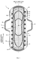
- FIG. 1 is a plan view showing the surface side of the absorbent article according to this embodiment.
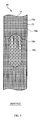
- FIG. 2 is a plan view for illustrating lengthwise concave sections and crosswise concave sections formed on the absorbent article according to this embodiment.
- FIG. 3 is a cross-sectional view taken along the line A-A in FIG. 2 .
- FIG. 4 is a cross-sectional view taken along the line B-B in FIG. 2 .
- an absorbent article 1 in this embodiment is elongated in a predetermined direction, and has a substantially rectangular absorbent member 10 for absorbing fluid such as menstrual blood, a back face sheet 30 provided on the back face of the absorbent member 10, a fluid-permeable surface member 20 covering the surface side of the absorbent member 10, and side sheets 25 arranged on both sides of the absorbent member 10 in a direction intersecting the longitudinal direction.
- an assumed position Z contacting against the bodily discharge opening at which the bodily discharge opening is assumed to come into contact against the absorbent article 1 is positioned closer to the front end than the middle in the longitudinal direction, on the center line in the width direction of the absorbent article 1.
- the absorbent member 10 has an absorbent body material 12 and thin paper (not shown) such as tissue paper and the like, the absorbent body material 12 being made of pulverized pulp, obtained by pulverizing sheet-like pulp, and a superabsorbent polymer.
- the absorbent body material 12 in the form of a sheet having a predetermined thickness is wrapped in the thin paper.
- the thin paper is a sheet that is fluid-permeable and has smaller openings than particles of the superabsorbent polymer so as to prevent the superabsorbent polymer from leaking out of the thin paper.
- the absorbent body material 12 may contain thermally melting fiber in order to prevent deformation in use.
- the back face sheet 30 is a thermoplastic and fluid-impermeable sheet made of materials such as polyethylene or polypropylene.
- the back face sheet 30 is sufficiently wider than the absorbent member 10. Throughout the entire periphery, the outer edge portion of the back face sheet 30 is positioned outside the outer edge portion of the absorbent member 10. Furthermore, on both sides in a direction intersecting the longitudinal direction (hereinafter, referred to as a width direction), holding sections 32 extending outward in the width direction are formed in a predetermined region centered, in the longitudinal direction, at the assumed position Z contacting against the bodily discharge opening.
- the surface member 20 is slightly wider than the absorbent member 10 in the width direction, is substantially as long as the back face sheet 30 in the longitudinal direction, and covers the entire area of the surface of the absorbent member 10.
- the surface member 20 is described later in detail.
- the side sheets 25 are appropriate nonwoven fabric made of synthetic resin fibers, such as air-through nonwoven fabric, spunbonded nonwoven fabric, or nonwoven fabric including spunbonded-meltblown-spunbonded layers.
- the surface member 20 is joined with a hot-melt adhesive to the surface side of the absorbent member 10, and a deep-groove section 19 is formed at a predetermined position by deep-groove embossing in which pressing is performed in the thickness direction using a pressing member heated to high temperature.
- the deep-groove section 19 formed by deep-groove embossing joins the absorbent member 10 and the surface member 20 more tightly.
- the formed deep-groove section 19 serves as a curve-inducing section for forming a curve such that the absorbent article 1 easily fits along the body when worn.
- three regions are defined by the deep-groove section 19. In the following description, the three regions are referred to as a first region 10a, a second region 10b, and a third region 10c, from the side of the front end along the longitudinal direction.
- the back face sheet 30 is joined with a hot-melt adhesive to the absorbent member 10 and the surface member 20 on the back face side. Furthermore, on the surface side, the side sheets 25 are joined with a hot-melt adhesive to an area from positions slightly overlapped with both side portions of the absorbent member 10 to the back face sheet.
- Line-like and flower-like shallow-groove sections 18 are formed by embossing using a pressing member heated to low temperature at positions where the surface member 20 and the side sheets 25 are overlapped. The shallow-groove sections 18 join the surface member 20 and the side sheets 25 more tightly.
- the outer edge portion of the absorbent article 1 is subjected to round sealing in which thermal fusion is performed at low temperature, and forms a reinforced round seal section 1a.
- the surface member 20 has a double-layered structure constituted by a surface sheet 14 that is disposed on the outside in the absorbent article 1, and an intermediate sheet 16 that is between the surface sheet 14 and the absorbent member 10.
- nonwoven fabric containing appropriate thermally melting fibers are used, and examples thereof include air-through nonwoven fabric made of cellulose fibers such as rayon or synthetic resin fibers, and spunlaced nonwoven fabric made of synthetic resin fibers or the like.
- the surface sheet 14 is positioned on the surface side that is brought into contact with the body, and thus the surface sheet 14 is a sheet softer than the thin paper.
- the intermediate sheet 16 is a highly fluid-permeable member that is denser than the surface sheet 14. When the intermediate sheet 16 is provided between the surface sheet 14 and the absorbent member 10, fluid that has permeated the surface sheet 14 is moved toward the intermediate sheet 16 drawing in more fluid than the surface sheet 14.
- FIG. 5 is a view showing the surface of the surface member according to this embodiment.
- FIG. 6 is a view showing the back face of the surface member according to this embodiment.
- a position corresponding to the second region when joined to the absorbent member 10 is indicated by a dashed-dotted line.
- the surface member 20 is provided so as to cover the absorbent member 10.
- a central predetermined region on the absorbent member 10 which is in the vicinity of the assumed position Z contacting against the bodily discharge opening on the absorbent article 1, the density of joined sections 15 subjected to thermal fusion is lower than that of the other regions.
- a region including the assumed position Z contacting against the bodily discharge opening, that is, the second region 10b positioned in the middle of the three defined regions 10a, 10b, and 10c corresponds to the central predetermined region, and the density of the joined sections 15 is low in this region.
- Lengthwise concave sections 14a as a plurality of first concave sections continuously formed along the longitudinal direction as a first direction, are provided spaced away from each other as appropriate in the width direction, throughout the entire area of the surface sheet 14 constituting the surface member 20. That is to say, the plurality of lengthwise concave sections 14a are provided from the front end of the absorbent article 1 toward the rear end, and the profile on the surface side obtained by cutting the surface sheet 14 in the width direction are in the form of waves.
- Crosswise concave sections 16a as a plurality of second concave sections continuously formed along the width direction as a second direction, are provided spaced away from each other as appropriate in the longitudinal direction, on the intermediate sheet 16 excluding the second region 10b. Furthermore, a plurality of narrow crosswise concave sections 16b continued to the crosswise concave sections 16a that are provided on both sides of the second region 10b in the width direction are provided spaced away from each other as appropriate in the second region 10b. More specifically, in the second region 10b, the plurality of narrow crosswise concave sections 16b are provided along the width direction of the absorbent article 1. The narrow crosswise concave sections 16b are arranged so as to intersect every other lengthwise concave section 14a of the plurality of lengthwise concave sections 14a provided spaced away from each other as appropriate in the width direction.
- the surface sheet 14 and the intermediate sheet 16 are overlapped such that the lengthwise concave sections 14a and the crosswise concave sections 16a and 16b intersect each other at substantially right angles, and the lengthwise concave sections 14a of the surface sheet 14 and the crosswise concave sections 16a and 16b of the intermediate sheet 16 are joined by thermal fusion at positions where the concave sections intersect each other, and thus the surface member 20 is integrally formed.
- the dot-like joined sections 15 are formed by thermal fusion at portions where the lengthwise concave sections 14a and the crosswise concave sections 16a and 16b intersect each other.
- portions of the lengthwise concave sections 14a provided on the surface sheet 14 projecting toward the intermediate sheet 16 and portions of the crosswise concave sections 16a provided on the intermediate sheet 16 projecting toward the surface sheet 14 are on a grid, and all the concave sections are joined at positions where they intersect each other (hereinafter, referred to as intersecting points) to form the joined sections 15 .
- joined sections 15 are formed at positions where portions of the lengthwise concave sections 14a provided on the surface sheet 14 projecting toward the intermediate sheet 16 and portions of the narrow crosswise concave sections 16b provided on the intermediate sheet 16 projecting toward the surface sheet 14 intersect each other.
- the joined sections 15 formed in the second region are alternately formed in both the longitudinal direction and the width direction, with respect to the joined sections 15 formed in the region outside the second region. More specifically, a spacing between the adjacent joined sections 15 in the second region 10b is substantially twice as large as a spacing between the adjacent joined sections 15 in the region outside the second region 10b, in both the longitudinal direction and the width direction.
- the second region 10b is thicker than the region other than the second region 10b. Since the second region 10b that is thicker than the other regions and provides tight fitting includes the assumed position Z contacting against the bodily discharge opening, the second region 10b fits to the bodily discharge opening when worn, and thus discharged fluid can be reliably absorbed and prevented from leaking to the outside. Furthermore, since the second region 10b is thick, and thus excellent cushioning properties and good feel are provided.
- the surface sheet 14 of this embodiment is provided with the lengthwise concave sections 14a continuously formed along the longitudinal direction, gaps are formed in the front-and-rear direction when worn between the surface sheet 14 and the body, and thus the air permeability is improved.
- the air permeability is secured at the region other than the second region 10b, which is comparatively away from the assumed position Z contacting against the bodily discharge opening, and thus discomfort of the wearer is alleviated by suppressing stuffiness and the like. Accordingly, it is possible to provide the absorbent article 1 that can be comfortably used.
- the surface member 20 of this embodiment is produced by, for example, the following method.
- FIG. 7 is a view for illustrating a method for producing the surface member.
- FIG. 8 is a conceptual diagram for illustrating the surface shape of a pair of rollers for producing the surface member.
- the surface sheet 14 and the intermediate sheet 16 are supplied from below and above respectively to a gap between two rollers 50 and 51 that are held by shafts provided in the same direction and opposed to each other in the vertical direction.
- a plurality of rib-like annular protrusions 51a extending in the circumferential direction are provided spaced away from each other in the axial direction, on the lower roller 51 disposed on the side of the surface sheet 14.
- a plurality of rib-like linear protrusions 50a extending along the axial direction are provided spaced away from each other in the circumferential direction, on the upper roller 50 disposed on the side of the intermediate sheet 16.
- segmented protrusions 50b obtained by segmenting the linear protrusions 50a in the axial direction are provided in a portion of the upper roller 50 for joining a portion at the position corresponding to the second region 10b of the surface member 20.
- the segmented protrusions 50b are arranged so as to be opposed to every other annular protrusion 51a, in the width direction, of the plurality of annular protrusions 51a provided on the lower roller 51.
- the segmented protrusions 50b are arranged so as to be opposed to every other annular protrusion 51a, in the circumferential direction, of the plurality of annular protrusions 51a provided on the lower roller 51.
- the surface sheet 14 is placed along the lower roller 51 and curved by a guide roller 52 provided in opposition to the lower roller 51, and thus the lengthwise concave sections 14a are formed.
- the guide roller 52 has annular protrusions 52a formed at a pitch equal to the annular protrusions 51a of the lower roller 51.
- the tip ends of the annular protrusions 51a and 52a are loosely engaged with each other without being in contact with the rollers 51 and 52 opposed thereto.
- the lengthwise concave sections 14a are formed on the surface sheet 14 from a position at which the surface sheet 14 passes through a gap between the lower roller 51 and the guide roller 52.
- the lower roller 51 has been heated to a temperature close to the melting point of thermally melting fibers contained in the surface sheet 14.
- the lengthwise concave sections 14a are formed to the extent that their cross-section is undulated.
- the intermediate sheet 16 is overlapped with the surface sheet 14 and held between the upper and lower rollers 50 and 51, the intermediate sheet 16 is placed along the upper roller 50 with a tensile force applied thereto, and thus the crosswise concave sections 16a and 16b are formed.
- the upper roller 50 has been heated to a temperature close to the melting point of thermally melting fibers contained in the intermediate sheet 16.
- the crosswise concave sections 16a and 16b are formed to the extent that their cross-section is undulated.
- the lengthwise concave sections 14a and the crosswise concave sections 16a and 16b formed before being held between the upper and lower rollers 50 and 51 the lengthwise concave sections 14a curved by the guide roller 52 is more clearly shaped than the crosswise concave sections 16a and 16b.
- the surface sheet 14 on which the lengthwise concave sections 14a are formed and the intermediate sheet 16 on which the crosswise concave sections 16a and 16b are formed are pressed and thermally fused at positions where the annular protrusions 51a and the linear protrusions 50a are opposed to each other, in a state where the surface sheet 14 and the intermediate sheet 16 are overlapped between the heated upper and lower rollers 50 and 51, as described above.
- the inventors of this absorbent article confirmed the absorptivity of the absorbent article 1 by the following test, the absorbent article 1 using the surface member 20 in which the surface sheet 14 has the lengthwise concave sections 14a, the intermediate sheet 16 has the crosswise concave sections 16a and 16b, and the lengthwise concave sections 14a and the crosswise concave sections 16a and 16b are joined at positions where the concave sections intersect each other, as described in the foregoing embodiment.
- Heat transfer rate (Qmax) is originally for measuring "coldness/warmth when an article is touched", and the value tends to be higher as the amount of fluid remaining on the surface of a surface sheet is larger.
- the degree of fluid remaining on the surface of a surface sheet (absorptivity of an absorbent article) is indicated by heat transfer rate (Qmax). If the absorptivity of an absorbent article (test piece) is high, the amount of fluid remaining on the surface of the surface sheet is small, and thus the value of heat transfer rate (Qmax) is small.
- the artificial menstrual blood fluid having a viscosity of approximately 22 to 26 mPa ⁇ s is prepared in advance.
- Test pieces are overlapped on absorbent members, and their both side portions are subjected to embossing, and thus test pieces are formed.
- the following absorbent members and surface members are used.
- a test piece on which a first surface member is overlapped is referred to as a first test piece
- a test piece on which a second surface member is overlapped is referred to as a second test piece
- a test piece on which a third surface member is overlapped is referred to as a third test piece.
- Non-treated pulp or treated pulp is wrapped in tissue paper, and cut into a size of 100 mm (length) x 60 mm (width) for use.
- the weight per unit area of the pulp is adjusted to 500 g/m 2 , and the density is to 0.09 g/cm 3 .
- the surface sheet and the intermediate sheet are overlapped, embossed, joined, and then cut into a size of 100 mm (length) x 60 mm (width) .
- three types of surface members below are used. All the surface members are air-through nonwoven fabric using polypropylene/polyester compound fiber.
- Surface member (corresponding to a conventional product) obtained by embossing with a roller whose circumferential face has a plurality of protrusions and a roller whose surface is smooth.
- the weight per unit area is 30 g/m 2 .
- Surface member (same as the region other than the second region in the foregoing embodiment) in which a surface sheet is provided with lengthwise concave sections, an intermediate sheet is provided with crosswise concave sections, and the lengthwise concave sections and the crosswise concave sections are joined at all the intersecting points thereof.
- the weight per unit area is 40 g/m 2 .
- the weight per unit area is 40 g/m 2
- the heat transfer rate (Qmax) is measured on five test pieces in each measurement, and is evaluated based on the measured values.
- the second test piece corresponding to the region other than the second region described in the foregoing embodiment and the third test piece corresponding to the second region have Qmax values that are smaller the Qmax value of the first test piece corresponding to a conventional example, more specifically, substantially half of the Qmax value.
- the surface member 20 is constituted by the surface sheet 14 and the intermediate sheet 16
- the lengthwise concave sections 14a in the longitudinal direction are formed on the surface sheet 14
- the crosswise concave sections 16a and 16b are formed on the intermediate sheet 16
- the lengthwise concave sections 14a and the crosswise concave sections 16a and 16b are joined at positions where the concave sections intersect each other, the highly absorptive absorbent article 1 that is provided with the surface member 20 having fluid-permeability higher than conventional absorbent articles is realized.
- the crosswise concave sections 16a are changed into the plurality of narrow crosswise concave sections 16b spaced away from each other in the width direction, and thus spacing between the adjacent joined sections 15 is wider than that in the region other than the second region 10b.
- the crosswise concave sections 16a may be continuously formed along the width direction, and the lengthwise concave sections 14a may be provided as a plurality of narrow lengthwise concave sections spaced away from each other along the longitudinal direction.
- each of the narrow crosswise concave sections 16b intersects one lengthwise concave section 14a to form one joined section 15.
- each of the narrow crosswise concave sections 16b or narrow lengthwise concave sections may intersect two or more lengthwise concave sections 14a or crosswise concave sections 16a to form a plurality of joined sections 15.
- the density of the joined sections 15 provided in the second region 10b is lower than the density of the joined sections 15 provided in the region outside the second region 10b.
- the joined sections 15 may be formed at substantially uniform density throughout the entire area of the surface member 20.
- FIG. 9 is a plan view showing an example of an absorbent article in which joined sections are formed at substantially uniform density throughout the entire area of a surface member.
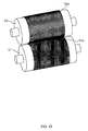
- FIG. 10 is a view for illustrating rollers for forming the surface member in which the joined sections are formed at substantially uniform density throughout the entire area.
- portions of the lengthwise concave sections 14a provided on the surface sheet 14 projecting toward the intermediate sheet 16 and portions of the crosswise concave sections 16a provided on the intermediate sheet 16 projecting toward the surface sheet 14 may be on a grid as in the region outside the second region 10b, and all the concave sections may be joined at positions where they intersect each other (intersecting points) to form the joined sections 15.
- all the concave sections may be joined at positions where they intersect each other (intersecting points) to form the joined sections 15.
- rollers for producing such a surface member of an absorbent article 2 are constituted by an upper roller 53 that is provided with linear protrusions 53a continuously formed in the width direction throughout the entire circumference, and the lower roller 51 that is provided with the annular protrusions 51a continuously formed in the circumferential direction throughout the entire circumference.
- the surface sheet 14 and the intermediate sheet 16 are overlapped after being inserted into a gap between the pair of upper and lower rollers 51 and 53, and portions that are held between the annular protrusions 51a and the linear protrusions 53a are joined, and thus the absorbent article 2 can be easily formed in which the joined sections 15 are formed at substantially uniform density throughout the entire area of the surface member 20.
- the absorbent member 10 is provided with one absorbent body material 12 in the middle in the width direction.
- side absorbent bodies may be provided along the longitudinal direction respectively on both end portions in the width direction on the absorbent member 10.
- standing gathers may be provided respectively at the both end portions instead of the side absorbent bodies.
- the assumed position Z contacting against the bodily discharge opening is positioned closer to the front end than the middle in the longitudinal direction.
- the assumed position Z contacting against the bodily discharge opening may be positioned in the middle in the longitudinal direction.
- thermoplastic and fluid-impermeable sheet made of materials such as polyethylene or polypropylene was used as the back face sheet 30.
- a sheet-like member also may be used in which a thermoplastic and fluid-impermeable sheet is contained, and, for example, thin paper, nonwoven fabric, or other materials are layered.
Landscapes
- Health & Medical Sciences (AREA)
- Engineering & Computer Science (AREA)
- Epidemiology (AREA)
- Life Sciences & Earth Sciences (AREA)
- Heart & Thoracic Surgery (AREA)
- Vascular Medicine (AREA)
- Biomedical Technology (AREA)
- Animal Behavior & Ethology (AREA)
- General Health & Medical Sciences (AREA)
- Public Health (AREA)
- Veterinary Medicine (AREA)
- Manufacturing & Machinery (AREA)
- Absorbent Articles And Supports Therefor (AREA)
Abstract
Description
- The present invention relates to an absorbent article for absorbing fluid.
- It is conventionally known that in order to absorb certain fluid, for example, menstrual blood, an absorbent article has an absorbent member for absorbing a fluid, and a surface member provided between the absorbent member and a human body in order that fluid discharged from the human body may be absorbed by the absorbent member as soon as possible and be moved away from the human body. It is also known that as a surface member of such an absorbent article, a product is used that is obtained, for example, by sending a thermoplastic film and a fibrous layer in an overlapped manner into a gap between two heated rollers, and melting the thermoplastic film with an embossing pattern provided on one of the rollers and a circumferential face, without any projections and depressions on the surface, of the other roller, thereby joining the thermoplastic film and the fibrous layer with opening sections or small embossed sections formed (for example, see
JP-A-02-102046 - The above-described surface member of the absorbent article is constituted by the two members such as the thermoplastic film and the fibrous layer, and the two members are joined in an overlapped manner with opening sections or small embossed sections formed. However, an action of the joined sections constituted by the opening sections or small embossed sections on the absorptivity of fluid has not been considered.
- The invention was made in view of the conventional problem, and it is an advantage thereof to provide an absorbent article having a surface member joined in consideration of absorptivity.
- In order to solve the above-described problem, a primary aspect of the invention is an absorbent article that has a longitudinal direction, a width direction, and a thickness direction, and that is worn on a body, including: an absorbent member for absorbing fluid; and a fluid-permeable surface member, wherein the surface member covers the absorbent member on the side of the body when worn in the thickness direction, the surface member includes a surface sheet and an intermediate sheet that is disposed closer to the absorbent member than the surface sheet in the thickness direction, the surface sheet has a first concave section along a first direction, the intermediate sheet has a second concave section along a second direction that intersects the first direction, and the surface sheet and the intermediate sheet are joined at positions where the first concave section and the second concave section intersect each other.
-
- [
FIG. 1 ] This is a plan view showing the surface side of an absorbent article according to an embodiment of the invention. - [
FIG. 2 ] This is a plan view for illustrating lengthwise concave sections and crosswise concave sections formed on the absorbent article according to this embodiment. - [
FIG. 3 ] This is a cross-sectional view taken along the line A-A inFIG. 2 . - [
FIG. 4 ] This is a cross-sectional view taken along the line B-B inFIG. 2 . - [
FIG. 5 ] This is a view showing a surface of a surface member according to this embodiment. - [
FIG. 6 ] This is a view showing a back face of the surface member according to this embodiment. - [
FIG. 7 ] This is a view for illustrating a method for producing the surface member. - [
FIG. 8 ] This is a conceptual diagram for illustrating the surface shape of a pair of rollers for producing the surface member. - [
FIG. 9 ] This is a plan view showing an example of an absorbent article in which joined sections are formed at substantially uniform density throughout the entire area of a surface member. - [
FIG. 10 ] This is a view for illustrating rollers for forming the surface member in which the joined sections are formed at substantially uniform density throughout the entire area. -
- 1 absorbent article, 1a round seal section, 2 absorbent article,
- 10 absorbent member, 10a first region, 10b second region,
- 10c third region, 12 absorbent body material, 14 surface sheet,
- 14a lengthwise concave section, 15 joined section,
- 16 intermediate sheet, 16a crosswise concave section,
- 16b narrow crosswise concave section, 18 shallow-groove section,
- 19 deep-groove section, 20 surface member, 25 side sheet,
- 30 back face sheet, 32 holding section, 50 upper roller,
- 50a linear protrusion, 50b segmented protrusion,
- 51 lower roller, 51a annular protrusion, 52 guide roller,
- 52a annular protrusion, 53 upper roller, 53a linear protrusion,
- Z assumed position contacting against the bodily discharge opening
- At least the following matters will be disclosed in the present specification and the drawings.
- An absorbent article that has a longitudinal direction, a width direction, and a thickness direction, and that is worn on a body, including: an absorbent member for absorbing fluid; and a fluid-permeable surface member, wherein the surface member covers the absorbent member on the side of the body when worn in the thickness direction, the surface member includes a surface sheet and an intermediate sheet that is disposed closer to the absorbent member than the surface sheet in the thickness direction, the surface sheet has a first concave section along a first direction, the intermediate sheet has a second concave section along a second direction that intersects the first direction, and the surface sheet and the intermediate sheet are joined at positions where the first concave section and the second concave section intersect each other.
- With this absorbent article, the surface sheet and the intermediate sheet are joined as described above at positions where the first concave section and the second concave section intersect each other, and thus the absorptivity of the absorbent article can be improved. Herein, the first concave section is formed on the surface of the surface sheet, and recessed toward the intermediate sheet, and the second concave section is formed on the surface of the intermediate sheet, and recessed toward the surface sheet.
- In this absorbent article, it is preferable that a plurality of the second concave sections are provided along the second direction, and intersect a plurality of the first concave sections.
- With this absorbent article, the plurality of second concave sections are provided along the second direction, and thus a plurality of joined sections can be provided. Thus, the absorptivity of the absorbent article can be improved. Furthermore, the second concave sections are joined to the first concave sections at a plurality of positions, and thus the absorptivity can be further improved.
- In this absorbent article, it is preferable that a plurality of the first concave sections are provided along the first direction, and intersect a plurality of the second concave sections.
- With this absorbent article, the plurality of first concave sections are provided along the first direction, and thus a plurality of joined sections can be provided. Thus, the absorptivity of the absorbent article can be improved. Furthermore, the first concave sections are joined to the second concave sections at a plurality of positions, and thus the absorptivity of the absorbent article can be further improved.
- In this absorbent article, it is preferable that the first direction is a longitudinal direction of the absorbent member.
- With this absorbent article, the first concave sections are provided in the longitudinal direction of the absorbent member, and thus the absorptivity of the absorbent article can be improved.
- In this absorbent article, it is preferable that the surface sheet and the intermediate sheet are nonwoven fabric containing thermally melting fiber, and that the joined sections are thermally fused.
- With this absorbent article, the surface sheet and the intermediate sheet can be joined by thermal fusion, and thus an absorbent article having high absorptivity can be provided without performing complicated operations such as application of an adhesive and the like. Furthermore, for example, if the absorbent article is an absorbent article that absorbs fluid such as menstrual blood, an absorbent article can be provided in which the fused section hardly slips off even when the wearer wearing the absorbent article vigorously moves. When worn, the first concave sections are recessed from the surface contacting against the skin toward clothing, and the second concave sections are recessed from the face contacting against the absorbent member toward the body.
- Hereinafter, the outline of the configuration of an absorbent article according to an embodiment of the invention shall be described. The absorbent article of this embodiment is a sanitary napkin. In the following description, the side that is brought into contact with the body is referred to as a surface side, the side that is brought into contact with an undergarment is referred to as a back face side, an end that is positioned on the front side of the human body when worn is referred to as a front end, and an end that is positioned on the rear side is referred to as a rear end.
-
FIG. 1 is a plan view showing the surface side of the absorbent article according to this embodiment.FIG. 2 is a plan view for illustrating lengthwise concave sections and crosswise concave sections formed on the absorbent article according to this embodiment.FIG. 3 is a cross-sectional view taken along the line A-A inFIG. 2 .FIG. 4 is a cross-sectional view taken along the line B-B inFIG. 2 . - As shown
FIGS. 1 to 4 , anabsorbent article 1 in this embodiment is elongated in a predetermined direction, and has a substantially rectangularabsorbent member 10 for absorbing fluid such as menstrual blood, aback face sheet 30 provided on the back face of theabsorbent member 10, a fluid-permeable surface member 20 covering the surface side of theabsorbent member 10, andside sheets 25 arranged on both sides of theabsorbent member 10 in a direction intersecting the longitudinal direction. - In the
absorbent article 1 of this embodiment, an assumed position Z contacting against the bodily discharge opening at which the bodily discharge opening is assumed to come into contact against theabsorbent article 1 is positioned closer to the front end than the middle in the longitudinal direction, on the center line in the width direction of theabsorbent article 1. - The
absorbent member 10 has anabsorbent body material 12 and thin paper (not shown) such as tissue paper and the like, theabsorbent body material 12 being made of pulverized pulp, obtained by pulverizing sheet-like pulp, and a superabsorbent polymer. Theabsorbent body material 12 in the form of a sheet having a predetermined thickness is wrapped in the thin paper. Herein, the thin paper is a sheet that is fluid-permeable and has smaller openings than particles of the superabsorbent polymer so as to prevent the superabsorbent polymer from leaking out of the thin paper. It should be noted that theabsorbent body material 12 may contain thermally melting fiber in order to prevent deformation in use. - The
back face sheet 30 is a thermoplastic and fluid-impermeable sheet made of materials such as polyethylene or polypropylene. Theback face sheet 30 is sufficiently wider than theabsorbent member 10. Throughout the entire periphery, the outer edge portion of theback face sheet 30 is positioned outside the outer edge portion of theabsorbent member 10. Furthermore, on both sides in a direction intersecting the longitudinal direction (hereinafter, referred to as a width direction), holdingsections 32 extending outward in the width direction are formed in a predetermined region centered, in the longitudinal direction, at the assumed position Z contacting against the bodily discharge opening. - The
surface member 20 is slightly wider than theabsorbent member 10 in the width direction, is substantially as long as theback face sheet 30 in the longitudinal direction, and covers the entire area of the surface of theabsorbent member 10. Thesurface member 20 is described later in detail. - The
side sheets 25 are appropriate nonwoven fabric made of synthetic resin fibers, such as air-through nonwoven fabric, spunbonded nonwoven fabric, or nonwoven fabric including spunbonded-meltblown-spunbonded layers. - In the
absorbent article 1, thesurface member 20 is joined with a hot-melt adhesive to the surface side of theabsorbent member 10, and a deep-groove section 19 is formed at a predetermined position by deep-groove embossing in which pressing is performed in the thickness direction using a pressing member heated to high temperature. The deep-groove section 19 formed by deep-groove embossing joins theabsorbent member 10 and thesurface member 20 more tightly. Furthermore, the formed deep-groove section 19 serves as a curve-inducing section for forming a curve such that theabsorbent article 1 easily fits along the body when worn. In this embodiment, three regions are defined by the deep-groove section 19. In the following description, the three regions are referred to as afirst region 10a, asecond region 10b, and athird region 10c, from the side of the front end along the longitudinal direction. - The
back face sheet 30 is joined with a hot-melt adhesive to theabsorbent member 10 and thesurface member 20 on the back face side. Furthermore, on the surface side, theside sheets 25 are joined with a hot-melt adhesive to an area from positions slightly overlapped with both side portions of theabsorbent member 10 to the back face sheet. Line-like and flower-like shallow-groove sections 18 are formed by embossing using a pressing member heated to low temperature at positions where thesurface member 20 and theside sheets 25 are overlapped. The shallow-groove sections 18 join thesurface member 20 and theside sheets 25 more tightly. - The outer edge portion of the
absorbent article 1 is subjected to round sealing in which thermal fusion is performed at low temperature, and forms a reinforcedround seal section 1a. - The
surface member 20 has a double-layered structure constituted by asurface sheet 14 that is disposed on the outside in theabsorbent article 1, and anintermediate sheet 16 that is between thesurface sheet 14 and theabsorbent member 10. - As materials of the
surface sheet 14 and theintermediate sheet 16, nonwoven fabric containing appropriate thermally melting fibers are used, and examples thereof include air-through nonwoven fabric made of cellulose fibers such as rayon or synthetic resin fibers, and spunlaced nonwoven fabric made of synthetic resin fibers or the like. Thesurface sheet 14 is positioned on the surface side that is brought into contact with the body, and thus thesurface sheet 14 is a sheet softer than the thin paper. Furthermore, theintermediate sheet 16 is a highly fluid-permeable member that is denser than thesurface sheet 14. When theintermediate sheet 16 is provided between thesurface sheet 14 and theabsorbent member 10, fluid that has permeated thesurface sheet 14 is moved toward theintermediate sheet 16 drawing in more fluid than thesurface sheet 14. -
FIG. 5 is a view showing the surface of the surface member according to this embodiment.FIG. 6 is a view showing the back face of the surface member according to this embodiment. InFIGS. 5 and6 , for the sake of convenience of this description, a position corresponding to the second region when joined to theabsorbent member 10 is indicated by a dashed-dotted line. - The
surface member 20 is provided so as to cover theabsorbent member 10. In a central predetermined region on theabsorbent member 10, which is in the vicinity of the assumed position Z contacting against the bodily discharge opening on theabsorbent article 1, the density of joinedsections 15 subjected to thermal fusion is lower than that of the other regions. In this embodiment, among the threeregions second region 10b positioned in the middle of the three definedregions sections 15 is low in this region. - Lengthwise
concave sections 14a, as a plurality of first concave sections continuously formed along the longitudinal direction as a first direction, are provided spaced away from each other as appropriate in the width direction, throughout the entire area of thesurface sheet 14 constituting thesurface member 20. That is to say, the plurality of lengthwiseconcave sections 14a are provided from the front end of theabsorbent article 1 toward the rear end, and the profile on the surface side obtained by cutting thesurface sheet 14 in the width direction are in the form of waves. - Crosswise
concave sections 16a, as a plurality of second concave sections continuously formed along the width direction as a second direction, are provided spaced away from each other as appropriate in the longitudinal direction, on theintermediate sheet 16 excluding thesecond region 10b. Furthermore, a plurality of narrow crosswiseconcave sections 16b continued to the crosswiseconcave sections 16a that are provided on both sides of thesecond region 10b in the width direction are provided spaced away from each other as appropriate in thesecond region 10b. More specifically, in thesecond region 10b, the plurality of narrow crosswiseconcave sections 16b are provided along the width direction of theabsorbent article 1. The narrow crosswiseconcave sections 16b are arranged so as to intersect every other lengthwiseconcave section 14a of the plurality of lengthwiseconcave sections 14a provided spaced away from each other as appropriate in the width direction. - The
surface sheet 14 and theintermediate sheet 16 are overlapped such that the lengthwiseconcave sections 14a and the crosswiseconcave sections concave sections 14a of thesurface sheet 14 and the crosswiseconcave sections intermediate sheet 16 are joined by thermal fusion at positions where the concave sections intersect each other, and thus thesurface member 20 is integrally formed. The dot-like joinedsections 15 are formed by thermal fusion at portions where the lengthwiseconcave sections 14a and the crosswiseconcave sections concave sections 14a, which are thin wall portions of thesurface sheet 14, and the crosswiseconcave sections intermediate sheet 16, are thermally fused to each other, thick wall portions of thesurface sheet 14 and theintermediate sheet 16 outside the lengthwiseconcave sections 14a and the crosswiseconcave sections surface sheet 14 and theintermediate sheet 16, and thus no joinedsection 15 is formed therein. Thus, a portion of thesurface member 20 in which the lengthwiseconcave sections 14a and the crosswiseconcave sections surface sheet 14 and theintermediate sheet 16 that are not pressed. - In the
surface member 20 of this embodiment, in a region outside thesecond region 10b, portions of the lengthwiseconcave sections 14a provided on thesurface sheet 14 projecting toward theintermediate sheet 16 and portions of the crosswiseconcave sections 16a provided on theintermediate sheet 16 projecting toward thesurface sheet 14 are on a grid, and all the concave sections are joined at positions where they intersect each other (hereinafter, referred to as intersecting points) to form the joinedsections 15 . On the other hand, in thesecond region 10b, joinedsections 15 are formed at positions where portions of the lengthwiseconcave sections 14a provided on thesurface sheet 14 projecting toward theintermediate sheet 16 and portions of the narrow crosswiseconcave sections 16b provided on theintermediate sheet 16 projecting toward thesurface sheet 14 intersect each other. Thus, the joinedsections 15 formed in the second region are alternately formed in both the longitudinal direction and the width direction, with respect to the joinedsections 15 formed in the region outside the second region. More specifically, a spacing between the adjacent joinedsections 15 in thesecond region 10b is substantially twice as large as a spacing between the adjacent joinedsections 15 in the region outside thesecond region 10b, in both the longitudinal direction and the width direction. Thus, thesecond region 10b is thicker than the region other than thesecond region 10b. Since thesecond region 10b that is thicker than the other regions and provides tight fitting includes the assumed position Z contacting against the bodily discharge opening, thesecond region 10b fits to the bodily discharge opening when worn, and thus discharged fluid can be reliably absorbed and prevented from leaking to the outside. Furthermore, since thesecond region 10b is thick, and thus excellent cushioning properties and good feel are provided. - Moreover, since the
surface sheet 14 of this embodiment is provided with the lengthwiseconcave sections 14a continuously formed along the longitudinal direction, gaps are formed in the front-and-rear direction when worn between thesurface sheet 14 and the body, and thus the air permeability is improved. Thus, the air permeability is secured at the region other than thesecond region 10b, which is comparatively away from the assumed position Z contacting against the bodily discharge opening, and thus discomfort of the wearer is alleviated by suppressing stuffiness and the like. Accordingly, it is possible to provide theabsorbent article 1 that can be comfortably used. - The
surface member 20 of this embodiment is produced by, for example, the following method.FIG. 7 is a view for illustrating a method for producing the surface member.FIG. 8 is a conceptual diagram for illustrating the surface shape of a pair of rollers for producing the surface member. - As shown in
FIG. 7 , regarding thesurface member 20, thesurface sheet 14 and theintermediate sheet 16 are supplied from below and above respectively to a gap between tworollers - As shown in
FIG. 8 , a plurality of rib-likeannular protrusions 51a extending in the circumferential direction are provided spaced away from each other in the axial direction, on thelower roller 51 disposed on the side of thesurface sheet 14. A plurality of rib-likelinear protrusions 50a extending along the axial direction are provided spaced away from each other in the circumferential direction, on theupper roller 50 disposed on the side of theintermediate sheet 16. When the upper andlower rollers surface sheet 14 and theintermediate sheet 16 supplied to a gap between the rollers are pressed and joined at positions where theannular protrusions 51a and thelinear protrusions 50a are opposed to each other. - In order to form the narrow crosswise
concave sections 16b, segmentedprotrusions 50b obtained by segmenting thelinear protrusions 50a in the axial direction are provided in a portion of theupper roller 50 for joining a portion at the position corresponding to thesecond region 10b of thesurface member 20. The segmentedprotrusions 50b are arranged so as to be opposed to every otherannular protrusion 51a, in the width direction, of the plurality ofannular protrusions 51a provided on thelower roller 51. Also in the circumferential direction, the segmentedprotrusions 50b are arranged so as to be opposed to every otherannular protrusion 51a, in the circumferential direction, of the plurality ofannular protrusions 51a provided on thelower roller 51. - Before the
surface sheet 14 is overlapped with theintermediate sheet 16 and held between the upper andlower rollers surface sheet 14 is placed along thelower roller 51 and curved by aguide roller 52 provided in opposition to thelower roller 51, and thus the lengthwiseconcave sections 14a are formed. Theguide roller 52 hasannular protrusions 52a formed at a pitch equal to theannular protrusions 51a of thelower roller 51. The tip ends of theannular protrusions rollers concave sections 14a are formed on thesurface sheet 14 from a position at which thesurface sheet 14 passes through a gap between thelower roller 51 and theguide roller 52. At that time, thelower roller 51 has been heated to a temperature close to the melting point of thermally melting fibers contained in thesurface sheet 14. Thus, even without a great pressing force, the lengthwiseconcave sections 14a are formed to the extent that their cross-section is undulated. - On the other hand, before the
intermediate sheet 16 is overlapped with thesurface sheet 14 and held between the upper andlower rollers intermediate sheet 16 is placed along theupper roller 50 with a tensile force applied thereto, and thus the crosswiseconcave sections upper roller 50 has been heated to a temperature close to the melting point of thermally melting fibers contained in theintermediate sheet 16. Thus, even without a great pressing force, the crosswiseconcave sections concave sections 14a and the crosswiseconcave sections lower rollers concave sections 14a curved by theguide roller 52 is more clearly shaped than the crosswiseconcave sections - The
surface sheet 14 on which the lengthwiseconcave sections 14a are formed and theintermediate sheet 16 on which the crosswiseconcave sections annular protrusions 51a and thelinear protrusions 50a are opposed to each other, in a state where thesurface sheet 14 and theintermediate sheet 16 are overlapped between the heated upper andlower rollers - The inventors of this absorbent article confirmed the absorptivity of the
absorbent article 1 by the following test, theabsorbent article 1 using thesurface member 20 in which thesurface sheet 14 has the lengthwiseconcave sections 14a, theintermediate sheet 16 has the crosswiseconcave sections concave sections 14a and the crosswiseconcave sections - Artificial menstrual blood is repeatedly dropped onto a surface of a test piece corresponding to absorbent articles, and the heat transfer rate (Qmax) is measured each time after dropping. At that time, as an apparatus for measuring heat transfer rate (Qmax) , a Finger-robot thermo labo (produced by KES Kato tech Co., Ltd.) is used.
- Heat transfer rate (Qmax) is originally for measuring "coldness/warmth when an article is touched", and the value tends to be higher as the amount of fluid remaining on the surface of a surface sheet is larger. Thus, the degree of fluid remaining on the surface of a surface sheet (absorptivity of an absorbent article) is indicated by heat transfer rate (Qmax). If the absorptivity of an absorbent article (test piece) is high, the amount of fluid remaining on the surface of the surface sheet is small, and thus the value of heat transfer rate (Qmax) is small. As the artificial menstrual blood, fluid having a viscosity of approximately 22 to 26 mPa·s is prepared in advance.
- Surface members are overlapped on absorbent members, and their both side portions are subjected to embossing, and thus test pieces are formed. The following absorbent members and surface members are used. Hereinafter, a test piece on which a first surface member is overlapped is referred to as a first test piece, a test piece on which a second surface member is overlapped is referred to as a second test piece, and a test piece on which a third surface member is overlapped is referred to as a third test piece.
- Non-treated pulp or treated pulp is wrapped in tissue paper, and cut into a size of 100 mm (length) x 60 mm (width) for use. The weight per unit area of the pulp is adjusted to 500 g/m2, and the density is to 0.09 g/cm3.
- The surface sheet and the intermediate sheet are overlapped, embossed, joined, and then cut into a size of 100 mm (length) x 60 mm (width) . Herein, for the sake of comparison, three types of surface members below are used. All the surface members are air-through nonwoven fabric using polypropylene/polyester compound fiber.
- Surface member (corresponding to a conventional product) obtained by embossing with a roller whose circumferential face has a plurality of protrusions and a roller whose surface is smooth. The weight per unit area is 30 g/m2.
- Surface member (same as the region other than the second region in the foregoing embodiment) in which a surface sheet is provided with lengthwise concave sections, an intermediate sheet is provided with crosswise concave sections, and the lengthwise concave sections and the crosswise concave sections are joined at all the intersecting points thereof. The weight per unit area is 40 g/m2.
- Surface member (same as the second region in the foregoing embodiment) in which the embossing density is lower than that of the second surface member. The weight per unit area is 40 g/m2
-
- 1. An acrylic plate in which an opening is formed at the center is placed on the surface member of the test piece. Herein, the acrylic plate has a size of, for example, 200 mm (length) x 100 mm (width), an opening size of 40 mm x 10 mm, and a weight of approximately 125 g.
- 2. A nozzle of an autoburette for dropping the artificial menstrual blood is disposed 10 mm from the upper face of the acrylic plate, above the opening of the acrylic plate.
- 3. The artificial menstrual blood is dropped on the test piece (first dropping: dropping
amount 3 ml, dropping rate 95 ml/min). - 4. At 60 seconds after starting the dropping of the artificial menstrual blood, the heat transfer rate at the surface of the surface member is measured (first measurement). More specifically, a contact temperature sensor of the Finger-robot thermo labo is brought into contact against the test piece at a position onto which the artificial menstrual blood was dropped. Herein, a jig is used in order to prevent a change in measurement conditions such as pressure of the contact temperature sensor that is brought into contact with the test piece every time in the repeated measurements.
- 5. After the first measurement of the heat transfer rate, the artificial menstrual blood is dropped onto the test piece (second dropping: dropping
amount 4 ml, dropping rate 95 ml/min). - 6. At 60 seconds after starting the second dropping of the artificial menstrual blood, the heat transfer rate at the surface of the surface member is measured (second measurement).
- 7. After the second measurement of the heat transfer rate, the artificial menstrual blood is dropped onto the test piece (third dropping: dropping
amount 3 ml, dropping rate 95 ml/min). - 8. At 60 seconds after starting the third dropping of the artificial menstrual blood, the heat transfer rate at the surface of the surface member is measured (third measurement).
- Following the above-described procedure, the heat transfer rate (Qmax) is measured on five test pieces in each measurement, and is evaluated based on the measured values.
-
0 to 0.30 hardly feel cold (hardly feel wet) 0.30 to 0.50 slightly cold (slightly feel wet) 0.50 or more cold (feel wet) -
1st test piece 2nd test piece 3rd test piece Qmax x 1st measurement 0.172 0.096 0.082 Qmax x 2nd measurement 0.187 0.107 0.092 Qmax x 3rd measurement 0.263 0.167 0.135 - As shown in Table 1, each time, the second test piece corresponding to the region other than the second region described in the foregoing embodiment and the third test piece corresponding to the second region have Qmax values that are smaller the Qmax value of the first test piece corresponding to a conventional example, more specifically, substantially half of the Qmax value. That is to say, when as in the
absorbent article 1 of the foregoing embodiment, thesurface member 20 is constituted by thesurface sheet 14 and theintermediate sheet 16, the lengthwiseconcave sections 14a in the longitudinal direction are formed on thesurface sheet 14, the crosswiseconcave sections intermediate sheet 16, and the lengthwiseconcave sections 14a and the crosswiseconcave sections absorbent article 1 that is provided with thesurface member 20 having fluid-permeability higher than conventional absorbent articles is realized. - In the foregoing embodiment, an example was described in which in the
second region 10b, the crosswiseconcave sections 16a are changed into the plurality of narrow crosswiseconcave sections 16b spaced away from each other in the width direction, and thus spacing between the adjacent joinedsections 15 is wider than that in the region other than thesecond region 10b. However, the crosswiseconcave sections 16a may be continuously formed along the width direction, and the lengthwiseconcave sections 14a may be provided as a plurality of narrow lengthwise concave sections spaced away from each other along the longitudinal direction. Furthermore, an example was described in which each of the narrow crosswiseconcave sections 16b intersects one lengthwiseconcave section 14a to form one joinedsection 15. However, each of the narrow crosswiseconcave sections 16b or narrow lengthwise concave sections may intersect two or more lengthwiseconcave sections 14a or crosswiseconcave sections 16a to form a plurality of joinedsections 15. - In the foregoing embodiment, an example was described in which the density of the joined
sections 15 provided in thesecond region 10b is lower than the density of the joinedsections 15 provided in the region outside thesecond region 10b. However, the joinedsections 15 may be formed at substantially uniform density throughout the entire area of thesurface member 20. -
FIG. 9 is a plan view showing an example of an absorbent article in which joined sections are formed at substantially uniform density throughout the entire area of a surface member.FIG. 10 is a view for illustrating rollers for forming the surface member in which the joined sections are formed at substantially uniform density throughout the entire area. - For example, as shown in
FIG. 9 , also in thesecond region 10b, portions of the lengthwiseconcave sections 14a provided on thesurface sheet 14 projecting toward theintermediate sheet 16 and portions of the crosswiseconcave sections 16a provided on theintermediate sheet 16 projecting toward thesurface sheet 14 may be on a grid as in the region outside thesecond region 10b, and all the concave sections may be joined at positions where they intersect each other (intersecting points) to form the joinedsections 15. For example, as shown inFIG. 10 , rollers for producing such a surface member of anabsorbent article 2 are constituted by anupper roller 53 that is provided withlinear protrusions 53a continuously formed in the width direction throughout the entire circumference, and thelower roller 51 that is provided with theannular protrusions 51a continuously formed in the circumferential direction throughout the entire circumference. Thesurface sheet 14 and theintermediate sheet 16 are overlapped after being inserted into a gap between the pair of upper andlower rollers annular protrusions 51a and thelinear protrusions 53a are joined, and thus theabsorbent article 2 can be easily formed in which the joinedsections 15 are formed at substantially uniform density throughout the entire area of thesurface member 20. - For the sake of convenience of this description, in the foregoing embodiment, a configuration was described in which the
absorbent member 10 is provided with oneabsorbent body material 12 in the middle in the width direction. However, there is no limitation to this. For example, side absorbent bodies may be provided along the longitudinal direction respectively on both end portions in the width direction on theabsorbent member 10. Alternatively, standing gathers may be provided respectively at the both end portions instead of the side absorbent bodies. - In the foregoing embodiment, an example was described in which the assumed position Z contacting against the bodily discharge opening is positioned closer to the front end than the middle in the longitudinal direction. However, the assumed position Z contacting against the bodily discharge opening may be positioned in the middle in the longitudinal direction.
- In the foregoing embodiment, as the
back face sheet 30, a thermoplastic and fluid-impermeable sheet made of materials such as polyethylene or polypropylene was used. However, a sheet-like member also may be used in which a thermoplastic and fluid-impermeable sheet is contained, and, for example, thin paper, nonwoven fabric, or other materials are layered. - The foregoing embodiments are merely for the purpose of elucidating the invention and are not to be interpreted as limiting the invention. The invention can of course be altered and improved without departing from the gist thereof and equivalents are intended to be embraced therein.
Claims (3)
- An absorbent article that has a longitudinal direction, a width direction, and a thickness direction, and that is worn on a body, comprising:an absorbent member for absorbing fluid; anda fluid-permeable surface member,wherein the surface member covers the absorbent member on the side of the body when worn in the thickness direction,the surface member includes a surface sheet and an intermediate sheet that is disposed closer to the absorbent member than the surface sheet in the thickness direction,the surface sheet has a first concave section along a first direction,the intermediate sheet has a second concave section along a second direction that intersects the first direction, andthe surface sheet and the intermediate sheet are joined at positions where the first concave section and the second concave section intersect each other.
- An absorbent article according to claim 1, wherein
a plurality of the second concave sections are provided along the second direction, and intersect a plurality of the first concave sections. - An absorbent article according to claim 1 or 2, wherein
a plurality of the first concave sections are provided along the first direction, and intersect a plurality of the second concave sections.
Applications Claiming Priority (2)
| Application Number | Priority Date | Filing Date | Title |
|---|---|---|---|
| JP2006319365A JP5054963B2 (en) | 2006-11-27 | 2006-11-27 | Absorbent articles |
| PCT/JP2007/072548 WO2008065945A1 (en) | 2006-11-27 | 2007-11-21 | Absorbent article |
Publications (2)
| Publication Number | Publication Date |
|---|---|
| EP2087864A1 true EP2087864A1 (en) | 2009-08-12 |
| EP2087864A4 EP2087864A4 (en) | 2013-06-26 |
Family
ID=39467737
Family Applications (1)
| Application Number | Title | Priority Date | Filing Date |
|---|---|---|---|
| EP07832278.1A Withdrawn EP2087864A4 (en) | 2006-11-27 | 2007-11-21 | Absorbent article |
Country Status (7)
| Country | Link |
|---|---|
| US (1) | US8591487B2 (en) |
| EP (1) | EP2087864A4 (en) |
| JP (1) | JP5054963B2 (en) |
| KR (1) | KR20090083375A (en) |
| CN (1) | CN101541277B (en) |
| TW (1) | TWI414280B (en) |
| WO (1) | WO2008065945A1 (en) |
Families Citing this family (56)
| Publication number | Priority date | Publication date | Assignee | Title |
|---|---|---|---|---|
| EP1447067B1 (en) | 2003-02-12 | 2007-12-05 | The Procter & Gamble Company | Thin and dry diaper |
| ES2314137T3 (en) | 2003-02-12 | 2009-03-16 | THE PROCTER & GAMBLE COMPANY | COMFORTABLE diaper. |
| DE112008000011B4 (en) | 2007-06-18 | 2013-11-28 | The Procter & Gamble Company | Disposable absorbent articles and their use |
| ES2443535T3 (en) | 2007-06-18 | 2014-02-19 | The Procter & Gamble Company | Disposable absorbent article with substantially continuous continuously distributed particle-shaped polymeric material and method |
| CN102014826A (en) | 2008-04-29 | 2011-04-13 | 宝洁公司 | Method of making absorbent core with strain resistant core cover |
| US9084699B2 (en) * | 2009-02-20 | 2015-07-21 | The Procter & Gamble Company | Absorbent article |
| JP5328586B2 (en) * | 2009-09-28 | 2013-10-30 | ユニ・チャーム株式会社 | Disposable body fluid absorbent article |
| EP2329803B1 (en) | 2009-12-02 | 2019-06-19 | The Procter & Gamble Company | Apparatus and method for transferring particulate material |
| JP5665338B2 (en) * | 2010-03-24 | 2015-02-04 | ユニ・チャーム株式会社 | Body fluid treatment article and method for producing the same |
| JP5684046B2 (en) | 2011-05-20 | 2015-03-11 | ユニ・チャーム株式会社 | Absorbent articles |
| PL3111903T5 (en) | 2011-06-10 | 2022-02-14 | The Procter And Gamble Company | Absorbent structure for absorbent articles |
| WO2012170781A1 (en) | 2011-06-10 | 2012-12-13 | The Procter & Gamble Company | Disposable diapers |
| ES2484695T5 (en) | 2011-06-10 | 2018-02-13 | The Procter & Gamble Company | Disposable diaper that has a reduced joint between the absorbent core and the backing sheet |
| PL2532328T3 (en) | 2011-06-10 | 2014-07-31 | Procter & Gamble | Method and apparatus for making absorbent structures with absorbent material |
| EP2717822B1 (en) | 2011-06-10 | 2019-06-05 | The Procter and Gamble Company | Absorbent core for disposable absorbent articles |
| EP2532329B1 (en) | 2011-06-10 | 2018-09-19 | The Procter and Gamble Company | Method and apparatus for making absorbent structures with absorbent material |
| PH12013502575A1 (en) | 2011-06-10 | 2014-02-10 | Procter & Gamble | Absorbent structure for absorbent articles |
| JP5863359B2 (en) * | 2011-09-22 | 2016-02-16 | ユニ・チャーム株式会社 | Absorbent articles |
| CN104010597B (en) * | 2011-12-21 | 2015-12-09 | Sca卫生用品公司 | For detecting visual for difference the method that feature puts on multiple article, and comprise all there is the different visual packaging detecting the article of feature |
| MX348890B (en) | 2012-11-13 | 2017-07-03 | Procter & Gamble | Absorbent articles with channels and signals. |
| EP2740450B1 (en) | 2012-12-10 | 2025-12-31 | The Procter & Gamble Company | Absorbent item with a high proportion of superabsorbent material |
| US9216116B2 (en) | 2012-12-10 | 2015-12-22 | The Procter & Gamble Company | Absorbent articles with channels |
| US9216118B2 (en) | 2012-12-10 | 2015-12-22 | The Procter & Gamble Company | Absorbent articles with channels and/or pockets |
| EP2740452B1 (en) | 2012-12-10 | 2021-11-10 | The Procter & Gamble Company | Absorbent article with high absorbent material content |
| EP2740449B1 (en) | 2012-12-10 | 2019-01-23 | The Procter & Gamble Company | Absorbent article with high absorbent material content |
| US8979815B2 (en) | 2012-12-10 | 2015-03-17 | The Procter & Gamble Company | Absorbent articles with channels |
| US10639215B2 (en) | 2012-12-10 | 2020-05-05 | The Procter & Gamble Company | Absorbent articles with channels and/or pockets |
| EP3254656B1 (en) | 2013-06-14 | 2021-11-10 | The Procter & Gamble Company | Absorbent article and absorbent core forming channels when wet |
| US9987176B2 (en) | 2013-08-27 | 2018-06-05 | The Procter & Gamble Company | Absorbent articles with channels |
| CN110013386B (en) | 2013-08-27 | 2021-10-01 | 宝洁公司 | Absorbent article with channels |
| CA2924828C (en) | 2013-09-16 | 2017-07-18 | The Procter & Gamble Company | Absorbent articles with channels and signals |
| US11207220B2 (en) | 2013-09-16 | 2021-12-28 | The Procter & Gamble Company | Absorbent articles with channels and signals |
| EP3351225B1 (en) | 2013-09-19 | 2021-12-29 | The Procter & Gamble Company | Absorbent cores having material free areas |
| ES2606320T3 (en) | 2013-12-19 | 2017-03-23 | The Procter & Gamble Company | Absorbent cores that have channel-forming areas and wrapping joints in c |
| US9789009B2 (en) | 2013-12-19 | 2017-10-17 | The Procter & Gamble Company | Absorbent articles having channel-forming areas and wetness indicator |
| EP2905001B1 (en) | 2014-02-11 | 2017-01-04 | The Procter and Gamble Company | Method and apparatus for making an absorbent structure comprising channels |
| WO2015134375A1 (en) | 2014-03-06 | 2015-09-11 | The Procter & Gamble Company | Multi-component topsheets |
| WO2015134371A1 (en) | 2014-03-06 | 2015-09-11 | The Procter & Gamble Company | Multi-component topsheets |
| JP2017510397A (en) | 2014-03-06 | 2017-04-13 | ザ プロクター アンド ギャンブル カンパニー | 3D substrate |
| US10271997B2 (en) | 2014-04-08 | 2019-04-30 | The Procter & Gamble Company | Absorbent articles having substrates having zonal treatments |
| EP2949300B1 (en) | 2014-05-27 | 2017-08-02 | The Procter and Gamble Company | Absorbent core with absorbent material pattern |
| JP5648144B1 (en) * | 2014-06-30 | 2015-01-07 | ユニ・チャーム株式会社 | Absorbent articles |
| JP5699242B1 (en) * | 2014-06-30 | 2015-04-08 | ユニ・チャーム株式会社 | Absorbent articles |
| CN107072835B (en) * | 2014-11-06 | 2021-03-02 | 宝洁公司 | Absorbent article including garment-facing laminate |
| RU2017133027A (en) | 2015-03-16 | 2019-04-16 | Дзе Проктер Энд Гэмбл Компани | Rugged Absorbent Products |
| CN107405242A (en) | 2015-03-16 | 2017-11-28 | 宝洁公司 | Absorbent article with improved core |
| MX2017014428A (en) | 2015-05-12 | 2018-04-10 | Procter & Gamble | Absorbent article with improved core-to-backsheet adhesive. |
| US10543129B2 (en) | 2015-05-29 | 2020-01-28 | The Procter & Gamble Company | Absorbent articles having channels and wetness indicator |
| US10973702B2 (en) | 2015-08-26 | 2021-04-13 | The Procter & Gamble Company | Absorbent articles having three dimensional substrates and indicia |
| EP3167859B1 (en) | 2015-11-16 | 2020-05-06 | The Procter and Gamble Company | Absorbent cores having material free areas |
| EP3238676B1 (en) | 2016-04-29 | 2019-01-02 | The Procter and Gamble Company | Absorbent core with profiled distribution of absorbent material |
| EP3238678B1 (en) | 2016-04-29 | 2019-02-27 | The Procter and Gamble Company | Absorbent core with transversal folding lines |
| EP3478235B1 (en) | 2016-07-01 | 2020-10-14 | The Procter and Gamble Company | Absorbent articles with improved topsheet dryness |
| JP6375354B2 (en) * | 2016-11-29 | 2018-08-15 | 大王製紙株式会社 | Absorbent articles |
| WO2021225169A1 (en) * | 2020-05-08 | 2021-11-11 | 株式会社瑞光 | Method for manufacturing wearable article |
| US20230181391A1 (en) * | 2020-05-11 | 2023-06-15 | Ontex Bv | Absorbent article with improved structural functionality communication |
Family Cites Families (17)
| Publication number | Priority date | Publication date | Assignee | Title |
|---|---|---|---|---|
| US3922329A (en) * | 1973-01-16 | 1975-11-25 | Hercules Inc | Methods of making network structures |
| JPS50111490A (en) | 1974-02-13 | 1975-09-02 | ||
| JPS5926502A (en) * | 1982-07-30 | 1984-02-10 | 大王製紙株式会社 | Paper diaper and production thereof |
| JPH02102046A (en) | 1988-09-30 | 1990-04-13 | Fibertec Corp | Fiber-film base material |
| US4863785A (en) | 1988-11-18 | 1989-09-05 | The James River Corporation | Nonwoven continuously-bonded trilaminate |
| JP2859725B2 (en) * | 1990-09-20 | 1999-02-24 | 花王株式会社 | Surface material of absorbent article and method of manufacturing the same |
| GB9200629D0 (en) * | 1992-01-13 | 1992-03-11 | British Tech Group | Method of and apparatus for obtaining nmr information |
| MX9300424A (en) | 1992-11-06 | 1994-05-31 | Kimberly Clark Co | FIBROUS LAMINATED FABRIC AND METHOD AND APPARATUS FOR THE MANUFACTURE OF THE SAME. |
| JP3215262B2 (en) * | 1994-06-03 | 2001-10-02 | ユニ・チャーム株式会社 | Disposable body fluid absorbent articles |
| IN189366B (en) * | 1996-02-12 | 2003-02-15 | Mcneil Ppc Inc | |
| US5865824A (en) * | 1997-04-21 | 1999-02-02 | Chen; Fung-Jou | Self-texturing absorbent structures and absorbent articles made therefrom |
| JP3875007B2 (en) * | 2000-09-01 | 2007-01-31 | ユニ・チャーム株式会社 | Absorbent article using surface layer having continuous filament and method for producing the same |
| JP3609361B2 (en) * | 2000-10-12 | 2005-01-12 | 花王株式会社 | Three-dimensional sheet material |
| JP3611838B2 (en) * | 2001-12-28 | 2005-01-19 | 花王株式会社 | Top sheet for absorbent articles |
| JP4198978B2 (en) * | 2002-12-05 | 2008-12-17 | ユニ・チャーム株式会社 | Long absorbent article |
| JP4124687B2 (en) * | 2003-03-31 | 2008-07-23 | 大王製紙株式会社 | Absorbent article and method for forming emboss in absorbent article |
| JP4275521B2 (en) * | 2003-12-25 | 2009-06-10 | ユニ・チャーム株式会社 | Panty liner |
-
2006
- 2006-11-27 JP JP2006319365A patent/JP5054963B2/en active Active
-
2007
- 2007-11-21 CN CN2007800432840A patent/CN101541277B/en not_active Expired - Fee Related
- 2007-11-21 WO PCT/JP2007/072548 patent/WO2008065945A1/en not_active Ceased
- 2007-11-21 US US12/444,682 patent/US8591487B2/en not_active Expired - Fee Related
- 2007-11-21 KR KR1020097009867A patent/KR20090083375A/en not_active Abandoned
- 2007-11-21 EP EP07832278.1A patent/EP2087864A4/en not_active Withdrawn
- 2007-11-26 TW TW096144765A patent/TWI414280B/en not_active IP Right Cessation
Also Published As
| Publication number | Publication date |
|---|---|
| JP5054963B2 (en) | 2012-10-24 |
| CN101541277B (en) | 2013-01-23 |
| EP2087864A4 (en) | 2013-06-26 |
| TWI414280B (en) | 2013-11-11 |
| CN101541277A (en) | 2009-09-23 |
| JP2008132084A (en) | 2008-06-12 |
| US8591487B2 (en) | 2013-11-26 |
| KR20090083375A (en) | 2009-08-03 |
| TW200913966A (en) | 2009-04-01 |
| US20100010464A1 (en) | 2010-01-14 |
| WO2008065945A1 (en) | 2008-06-05 |
Similar Documents
| Publication | Publication Date | Title |
|---|---|---|
| US8591487B2 (en) | Absorbent article including a surface member with concaved sections | |
| JP5210553B2 (en) | Absorbent articles | |
| JP6214598B2 (en) | Absorbent articles | |
| KR101608560B1 (en) | Absorptive article | |
| TWI691313B (en) | Absorbent article | |
| JP5792997B2 (en) | Absorbent articles | |
| JP2009519098A (en) | Absorbent article | |
| WO2011036964A1 (en) | Disposable wearing article capable of absorbing bodily fluids | |
| CN107072831B (en) | absorbent articles | |
| JP2003126147A (en) | Surface sheet for absorbent articles | |
| JP6355808B2 (en) | Absorbent articles | |
| JPS6176156A (en) | Manufacturing method for non-planar absorbent products | |
| CN106470650B (en) | Absorbent commodity | |
| TWI652052B (en) | Absorbent article | |
| CN106470655B (en) | Absorbent article | |
| JP4972384B2 (en) | Absorbent articles | |
| CN108348376B (en) | absorbent articles | |
| JP2016221237A (en) | Absorbent article | |
| US9949880B2 (en) | Absorbent article with embedded lateral topsheets | |
| JP2012130363A (en) | Absorbent article | |
| JP6646441B2 (en) | Absorbent articles | |
| CN104837452A (en) | Absorbent article | |
| JP6308646B2 (en) | Absorbent articles | |
| JP2020178981A (en) | Absorbent article for light incontinence | |
| JP2021132920A (en) | Absorbent article |
Legal Events
| Date | Code | Title | Description |
|---|---|---|---|
| PUAI | Public reference made under article 153(3) epc to a published international application that has entered the european phase |
Free format text: ORIGINAL CODE: 0009012 |
|
| 17P | Request for examination filed |
Effective date: 20090529 |
|
| AK | Designated contracting states |
Kind code of ref document: A1 Designated state(s): AT BE BG CH CY CZ DE DK EE ES FI FR GB GR HU IE IS IT LI LT LU LV MC MT NL PL PT RO SE SI SK TR |
|
| DAX | Request for extension of the european patent (deleted) | ||
| A4 | Supplementary search report drawn up and despatched |
Effective date: 20130527 |
|
| RIC1 | Information provided on ipc code assigned before grant |
Ipc: A61F 13/49 20060101ALI20130521BHEP Ipc: A61F 13/539 20060101ALI20130521BHEP Ipc: A61F 13/537 20060101ALI20130521BHEP Ipc: A61F 13/511 20060101ALI20130521BHEP Ipc: A61F 13/472 20060101ALI20130521BHEP Ipc: A61F 13/15 20060101AFI20130521BHEP Ipc: A61F 13/475 20060101ALI20130521BHEP |
|
| STAA | Information on the status of an ep patent application or granted ep patent |
Free format text: STATUS: THE APPLICATION IS DEEMED TO BE WITHDRAWN |
|
| 18D | Application deemed to be withdrawn |
Effective date: 20140103 |