EP2087376B1 - Luap scintillator - Google Patents
Luap scintillator Download PDFInfo
- Publication number
- EP2087376B1 EP2087376B1 EP07871576.0A EP07871576A EP2087376B1 EP 2087376 B1 EP2087376 B1 EP 2087376B1 EP 07871576 A EP07871576 A EP 07871576A EP 2087376 B1 EP2087376 B1 EP 2087376B1
- Authority
- EP
- European Patent Office
- Prior art keywords
- temperature
- scintillator crystal
- crystal
- rate
- hours
- Prior art date
- Legal status (The legal status is an assumption and is not a legal conclusion. Google has not performed a legal analysis and makes no representation as to the accuracy of the status listed.)
- Not-in-force
Links
Images




Classifications
-
- G—PHYSICS
- G01—MEASURING; TESTING
- G01T—MEASUREMENT OF NUCLEAR OR X-RADIATION
- G01T1/00—Measuring X-radiation, gamma radiation, corpuscular radiation, or cosmic radiation
- G01T1/16—Measuring radiation intensity
- G01T1/20—Measuring radiation intensity with scintillation detectors
- G01T1/202—Measuring radiation intensity with scintillation detectors the detector being a crystal
Definitions
- This disclosure relates generally to a scintillator material and more particularly to a method for improving the performance properties of Cerium (Ce) doped LuAP (Lutetium Aluminum Perovskite) scintillator material.
- a major goal of well logging is to gain insight into the reservoir and thereby maximize the amount of hydrocarbons recovered from an earth formation and in order to better develop techniques and methods to accomplish this, it is helpful to know as much as possible about the physical characteristics of the earth formation surrounding a well. For example, by continuously monitoring the oil saturation in an earth formation, which is typically expressed as a percentage by volume of oil in the pore space, secondary and tertiary techniques may be developed to use this oil saturation to enhance the recovery of the hydrocarbons.
- scintillation detectors are used to detect and measure the number and energy of gamma rays present in an earth formation.
- a scintillation detector includes a crystal and a photomultiplier, such that when a gamma ray becomes incident upon the crystal, the incident gamma ray imparts energy to electrons in the crystal through Compton scattering, photoelectric absorption, and pair production. This introduction of energy to the electrons in the crystal causes the detector crystal lattice to become excited and when the crystal de-excites, visible or near-visible light is emitted.
- This scintillation is then detected by the photomultiplier and transformed into an electrical pulse having a frequency and amplitude responsive to the number of gamma rays and their respective energy levels, wherein the characteristics of the electrical pulse is typically recorded in a log for analysis.
- LuAP Lutetium Aluminum Perovskite
- scintillation material utilizes Lutetium Aluminum Perovskite, or LuAP, as its scintillation material.
- LuAP has been known for a number of years and is recognized as a promising host for radiation detection applications due to its exceptional combination of properties, such as high stopping power, very short decay times and reasonably good energy resolution.
- most current methods for producing LuAP crystals for use in scintillation detectors are unreliable in consistently producing crystals that have both acceptable light output characteristics and material uniformity. This lack of consistency is undesirable because of its direct effect on detector resolution, photopeak shape and detector-to-detector consistency.
- LuAP scintillation materials having unacceptable light output characteristics and/or material uniformity tend to be unusable for many applications due to decreased logging speeds and/or increasing tool-to-tool variations.
- a method for improving the light output and uniformity of a LuAP scintillator crystal includes disposing the scintillator crystal in a predetermined oxidizing environment; annealing the crystal in said predetermined environment to a threshold temperature at a temperature change rate, wherein the threshold temperature is between about 1200°C to about 1650°C; cooling the crystal in the predetermined environment to a third temperature at a first cool down rate; soaking the crystal in said predetermined environment at the third temperature for a third soaking period; and cooling the scintillator crystal to a final temperature.
- LuAP scintillation detector having an improved light output and uniformity
- the LuAP scintillation detector includes an Lutetium Aluminum Perovskite (LuAP) scintillation material that has been annealed using a predetermined annealing process such that when the LuAP scintillation material is impinged upon by radiation, the LuAP scintillation material generates scintillation energy having a frequency and amplitude responsive to the radiation.
- LuAP Lutetium Aluminum Perovskite
- a method for improving the performance properties of a scintillator crystal such as a LuAP scintillator crystal, wherein the performance properties include the light output and material uniformity of the LuAP scintillator.
- This improvement will lead to a better utilization of the downhole tool by allowing for an increase in logging speed and a decrease in tool-to-tool variation by improving the detector resolution, the photopeak shape and the detector-to-detector consistency over existing LuAP scintillators.
- Figure 1 a plot of Cesium resolution measurements for an LuAP Crystal cube, in accordance with the prior art (i.e. before annealing), is shown.
- Figure 1 illustrates six Cs 137 662 keV peaks for the six cube orientations, wherein the light output was measured with each of the six sides facing the photomultiplier tube (hereinafter "PMT"). As illustrated and understood by one skilled in the art, the plot illustrates a poor level of uniformity as indicated by the scattered pattern of the six measurements.
- PMT photomultiplier tube
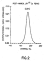
- plot of Figure 2 illustrates a higher level of light output as indicated by the positions of the peaks being disposed farther to the right hand side of the graph. Also, the more tightly grouped scatter pattern of the six measurements indicates a higher level of uniformity than that shown in Figure 1 .
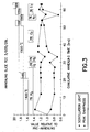
- FIG. 3 a plot illustrating the results from a series of various annealing treatments performed on a single sample of LuAP material is shown, wherein the different annealing treatments varied in temperature, duration and atmospheric environment.
- the illustrated annealing treatments are solely for illustrative purposes and are not intended to be limiting of the scope of the present invention.
- One skilled in the art will readily recognize that numerous alternative annealing techniques are applicable to the present invention.
- the single sample of LuAP material in Figure 3 was annealed in an atmospheric environment comprised of nitrogen gas with various amount of either hydrogen or oxygen.
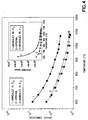
- FIG. 4 a plot illustrating the resistivity as a function of temperature for several LuAP samples which have been annealed via application of the method of the present invention is shown.
- a take-up of oxygen into the crystal lattice of the LuAP occurs.
- a portion of the oxygen vacancies within the crystal lattice of the sample are filled, thus reducing the concentration of vacancies within the sample material.
- the LuAP sample that was annealed within an oxidizing environment demonstrates a higher level of resistivity.
- an oxidizing environment can be established via any method and/or device suitable to the desired end purpose, such as, but not limited to, an introduction of oxygen, Carbon Dioxide and/or Nitrogen Oxides into the environment and/or by saturating an inert gas with water vapor. It should further be appreciated that the use of an oxidizing species, such as oxygen or water vapor, illustrates that the source of the oxidizing gas species is essentially equivalent. As such, the chemical potential of the oxidizing component of the gas mixture is one critical element of the atmosphere in contact with the crystal.
- atmospheres where a controlled degree of oxidation can be achieved include a gas composition that may be a mixture of CO/CO 2 and/or H 2 /H 2 O.
- a gas composition that may be a mixture of CO/CO 2 and/or H 2 /H 2 O.
- the aforementioned atmospheres are not intended to be limiting in scope and are solely for illustrative purposes.
- the desired LuAP crystal material may be typically disposed in a perovskite phase, the material actually prefers to be in the garnet phase. Thus, annealing the LuAP crystal material to very high temperatures can cause some or all of the LuAP crystal material to convert to the garnet phase and be useless.
- the LuAP crystal material may be doped with cerium to produce the scintillation light, and although the Ce3+ oxidation state is preferred since it produces the scintillation light, Cerium can exist in either the Ce3+ or Ce4+ oxidation state in the lattice.
- Ce3+ oxidation state is preferred since it produces the scintillation light
- Cerium can exist in either the Ce3+ or Ce4+ oxidation state in the lattice.
- annealing in an oxidizing environment presents the possibility of converting some fraction of the Ce3+ to Ce4+, wherein Ce4+ ions can trap excited electrons and cause undesirable reduction of scintillation light.
- FIG. 5 a plot illustrating resolution and light output measurements for a cubed shaped LuAP crystal material that was annealed in an oxidizing environment for different lengths of time is shown.
- the increase in the light output relative to the increase in annealing time is indicated by the movement of the peaks toward the right hand side of the plot. It should be appreciated that this movement of the peaks toward the right hand side of the plot shows decreased improvement after approximate six (6) hours of annealing time.
- Figure 6 a plot illustrating the relative light output and resolution versus annealing time is shown which illustrates an improvement following a re-polishing of the detector to remove the garnet phase that grew on the surface of the scintillator sample.
- the detector performance was still improving with up to 9 hours of annealing. Therefore, it should be appreciated that significant improvements can be made to "as grown" LuAP crystal materials by annealing the "as-grown" LuAP crystal materials in an oxidizing environment, in accordance with the present invention.
- annealing of LuAP crystals must typically be performed at temperatures greater than 1300°C in order for oxygen to diffuse into the crystal lattice and fill any oxygen vacancies within the crystal.
- one annealing temperature range for LuAP crystals that produce a positive result includes the temperature range of about 1400°C to about 1500°C.
- care may be taken to not allow the annealing temperature to exceed a predetermined threshold limit.
- the rate at which the oxygen vacancies are filled typically increases with temperature, if the annealing temperature is allowed to be too high (e.g. around 1600°C for LuAP crystals) the garnet phase formation may be accelerated.
- the amount of oxygen disposed within the annealing environment must further be considered when annealing the scintillator crystal. Although at certain oxygen concentration levels the rate at which the oxygen vacancies are filled increases, at higher oxygen concentration levels the conversion rate of Ce +3 to Ce +4 , will eventually take place. Hence, the amount of oxygen disposed within the annealing environment must be considered. As above, this is also undesirable due to the reduction in the light output response of the crystal.
- annealing the scintillator crystal involves the rate at which the crystal is heated and/or cooled. This is because if the crystal is heated or cooled too rapidly, the crystal may crack. In fact, one skilled in the art will readily appreciate that the larger the crystal, the slower the heating/cooling rate required may be.
- a block diagram illustrating a first embodiment of a method 200 for improving the light output of a scintillator crystal includes disposing the scintillator crystal in a controlled atmosphere that includes a gas or mixture of gases that provide an oxidizing environment, as shown in operational block 202.
- a controlled atmosphere that includes a gas or mixture of gases that provide an oxidizing environment, as shown in operational block 202.
- one such environment may include Nitrogen comprising at least 0.1 % Oxygen, wherein an Oxygen content of about 3% is preferred for certain conditions.
- other gases suitable to the desired end purpose may be substituted for Nitrogen, such as Helium, Neon, Krypton, Argon, Xenon and/or Radon.
- any oxidizer suitable to the desired end purpose may be used, such as Oxygen, Carbon Dioxide, Nitrogen Oxides, air and/or water vapor.
- the scintillation crystal is heated in the oxidizing gas environment, as shown in operational block 204.
- the crystal may be heated to a temperature which is within the range of about 800°C to about 1200°C, with one acceptable temperature being about 1000°C for certain conditions.
- the rate at which the scintillation crystal is heated may be within the range of up to about 10°C/min, with one acceptable heat up rate being about 5°C/min for certain conditions.
- the scintillation crystal may then be equilibrated or 'soaked' in the oxidizing gas environment at this temperature for a predetermined soaking period of about 0.5 hours to about 2 hours, as shown in operational block 206.
- the predetermined soaking period may be predicated on certain conditions, such as the size of the scintillation crystal. For example, one acceptable soaking period for a 1cm 3 scintillation crystal is about 2 hours, whereas for a larger scintillation crystal the soaking period may be longer than about 2 hours. Additionally, in some situations, this soaking period may not be required, thus allowing the crystal to be heated to a threshold temperature without soaking.
- the scintillation crystal may then be heated to a threshold temperature, as shown in operational block 208, wherein the threshold temperature may be within the range of between about 1200°C to 1650°C and wherein the rate at which the crystal is heated may be about 2°C/min. It should be appreciated that one threshold temperature is about 1450°C for certain conditions.
- the scintillation crystal may then be 'soaked' in this environment at this threshold temperature for a predetermined soaking period, as shown in operational block 210, wherein the predetermined soaking period may be within the range of about 1 hour to 24 hours. It should be appreciated that for a 1cm 3 scintillation crystal one acceptable threshold temperature is about 1450°C and one acceptable predetermined soaking time period is about 24 hours.
- the scintillation crystal is cooled to a temperature range of about 800°C to about 1200°C at a predetermined cool down rate, as shown in operational block 212, wherein the predetermined cool down rate may be in the range of about 1°C/min to about 10°C/min.
- the predetermined cool down rate may be in the range of about 1°C/min to about 10°C/min.
- one temperature is about 1000°C and one cool down rate is about 2°C/min.
- the scintillation crystal may be equilibrated or 'soaked' at this temperature for a predetermined soaking period of time, as shown in operational block 214, wherein the predetermined soaking period of time may be in the range of about 0.5 hours to about 10 hours. As above, under certain conditions, such as for a 1cm 3 scintillation crystal one acceptable soaking period of time is about 2 hours. Additionally, in some situations, this soaking period may not be required, thus allowing the crystal to be cooled to a final temperature without soaking.
- the scintillation crystal is then cooled to a final temperature, such as room temperature, at a cool down rate in the range of up to 10°C/min, as shown in operational block 216.
- a cool down rate in the range of up to 10°C/min, as shown in operational block 216.
- one acceptable cool down rate may be about 5°C/min.
- the heat up rate and/or cool down rate is typically responsive to the size of the crystal being annealed. As such, it is contemplated that any appropriate heat up rate and/or cool down rate may be used so as long as the selected heat up rate and/or cool down rate does not lead to physical damage to the crystal either from thermal shock and/or from an inadvertent phase transition.
- a block diagram illustrating a second embodiment of a method 300 for improving the light output of a scintillator crystal includes growing a crystal within a predetermined growing environment, as shown in operational block 302, wherein the crystal may be annealed during the cool down of the grown crystal.
- the crystal may be cooled down to the threshold temperature, wherein the threshold temperature may be within the range of between about 1200°C to 1650°C, as shown in operational block 304.
- the crystal is then 'soaked' at this threshold temperature in an oxidizing atmosphere for a predetermined soaking period, as shown in operational block 306, wherein the predetermined soaking period may be within the range of about 1 hour to 24 hours.
- one acceptable threshold temperature is about 1450°C and one acceptable soaking time period is about 24 hours.
- the scintillation crystal is cooled to a temperature range of about 800°C to about 1200°C at a cool down rate of about 1°C/min to about 10°C/min, as shown in operational block 308.
- one acceptable temperature is about 1000°C and one acceptable cool down rate is about 2°/min.
- the scintillation crystal is equilibrated or 'soaked' at the temperature for a predetermined soaking period of time, as shown in operational block 310, wherein the predetermined soaking period of time may be in the range of about 0.5 hours to about 10 hours. As above, under certain conditions, such as for a 1cm 3 scintillation crystal one acceptable predetermined soaking period of time is about 2 hours.
- the scintillation crystal is then cooled to a final temperature at a cool down rate in the range of up to 10°C/min, as shown in operational block 312, wherein the final temperature may be about room temperature.
- one acceptable cool down rate may be about 5°C/min.
- the scintillator crystal may be disposed in different environments having atmospheres comprised of different elements. For example, the crystal may be grown in one environment while the annealing may occur in another environment.
- the LuAP scintillator of the present invention is ideal for use in spectroscopy applications (above ground and down hole applications), such as density measurements, sigma measurement (thermal neutron die-away) and gamma-ray spectroscopy.
- the LuAP scintillator of the present invention has applicability not only in geological based applications, but also other applications as well, such as nuclear radiation applications.
- the LuAP scintillator of the present invention may be used in almost any application that employs other types of scintillators, such as NaI, CsI, BGO, GSO, and LSO, including medical, environmental, and homeland security applications.
- the methods of Figure 7 and Figure 8 may be implemented, in part or in whole, using a controller operating in response to a computer program.
- the controller may include, but not be limited to, a processor(s), computer(s), memory, storage, register(s), timing, interrupt(s), communication interface(s), and input/output signal interface(s), as well as combination comprising at least one of the foregoing.
- the invention may be embodied, in part or in whole, in the form of a computer or controller implemented processes.
- the invention may also be embodied in the form of computer program code containing instructions embodied in tangible media, such as floppy diskettes, CD-ROMs, hard drives, and/or any other computer-readable medium, wherein when the computer program code is loaded into and executed by a computer or controller, the computer or controller becomes an apparatus for practicing the invention.
- the invention can also be embodied in the form of computer program code, for example, whether stored in a storage medium, loaded into and/or executed by a computer or controller, or transmitted over some transmission medium, such as over electrical wiring or cabling, through fiber optics, or via electromagnetic radiation, wherein when the computer program code is loaded into and executed by a computer or a controller, the computer or controller becomes an apparatus for practicing the invention.
- computer program code segments may configure the microprocessor to create specific logic circuits.
Landscapes
- Chemical & Material Sciences (AREA)
- Crystallography & Structural Chemistry (AREA)
- Physics & Mathematics (AREA)
- Health & Medical Sciences (AREA)
- Life Sciences & Earth Sciences (AREA)
- General Physics & Mathematics (AREA)
- High Energy & Nuclear Physics (AREA)
- Molecular Biology (AREA)
- Spectroscopy & Molecular Physics (AREA)
- Measurement Of Radiation (AREA)
- Luminescent Compositions (AREA)
- Crystals, And After-Treatments Of Crystals (AREA)
Description
- This disclosure relates generally to a scintillator material and more particularly to a method for improving the performance properties of Cerium (Ce) doped LuAP (Lutetium Aluminum Perovskite) scintillator material.
- A major goal of well logging is to gain insight into the reservoir and thereby maximize the amount of hydrocarbons recovered from an earth formation and in order to better develop techniques and methods to accomplish this, it is helpful to know as much as possible about the physical characteristics of the earth formation surrounding a well. For example, by continuously monitoring the oil saturation in an earth formation, which is typically expressed as a percentage by volume of oil in the pore space, secondary and tertiary techniques may be developed to use this oil saturation to enhance the recovery of the hydrocarbons.
- It is well known in the oil and gas industry that physical characteristics of the formation surrounding a well, such as the chemical content of the formation and the fluid in the formation, may be determined from radiation emanating from the formation, wherein the radiation may be either naturally originating in the formation or the radiation may be induced by irradiating the formation during the well logging operation. As such, scintillation detectors are typically employed to analyze the energy content characteristics of this radiation to enable the determination of pulse-height spectrum characteristics of the gamma-rays being emitted by the formation.
- As is also well known, scintillation detectors are used to detect and measure the number and energy of gamma rays present in an earth formation. Typically, a scintillation detector includes a crystal and a photomultiplier, such that when a gamma ray becomes incident upon the crystal, the incident gamma ray imparts energy to electrons in the crystal through Compton scattering, photoelectric absorption, and pair production. This introduction of energy to the electrons in the crystal causes the detector crystal lattice to become excited and when the crystal de-excites, visible or near-visible light is emitted. This scintillation is then detected by the photomultiplier and transformed into an electrical pulse having a frequency and amplitude responsive to the number of gamma rays and their respective energy levels, wherein the characteristics of the electrical pulse is typically recorded in a log for analysis.
- One particular type of scintillation detector utilizes Lutetium Aluminum Perovskite, or LuAP, as its scintillation material. LuAP has been known for a number of years and is recognized as a promising host for radiation detection applications due to its exceptional combination of properties, such as high stopping power, very short decay times and reasonably good energy resolution. Unfortunately, however, most current methods for producing LuAP crystals for use in scintillation detectors are unreliable in consistently producing crystals that have both acceptable light output characteristics and material uniformity. This lack of consistency is undesirable because of its direct effect on detector resolution, photopeak shape and detector-to-detector consistency. As such, LuAP scintillation materials having unacceptable light output characteristics and/or material uniformity tend to be unusable for many applications due to decreased logging speeds and/or increasing tool-to-tool variations.
- 'Scintillation and Optical Properties of LuAP and LuYAP Crystals' by Piotr Szupryczynski, Merry A. Spurrier, Claudia J. Rawn, Charles L. Melcher and A. Andrew Carey discusses scintillation mechanisms of LuAP crystals and optimization of the crystal growth process. (2005 IEEE Nuclear Science Symposium Conference Record page 1305). In the reference annealing experiments were performed to examine the effect of atmosphere on scintillation properties. Some of the annealing of the LuAP crystals in the investigation were carried out in air at temperatures of 1500°C.
- A method for improving the light output and uniformity of a LuAP scintillator crystal is provided, wherein the method includes disposing the scintillator crystal in a predetermined oxidizing environment; annealing the crystal in said predetermined environment to a threshold temperature at a temperature change rate, wherein the threshold temperature is between about 1200°C to about 1650°C; cooling the crystal in the predetermined environment to a third temperature at a first cool down rate; soaking the crystal in said predetermined environment at the third temperature for a third soaking period; and cooling the scintillator crystal to a final temperature.
- An LuAP scintillation detector having an improved light output and uniformity is provided, wherein the LuAP scintillation detector includes an Lutetium Aluminum Perovskite (LuAP) scintillation material that has been annealed using a predetermined annealing process such that when the LuAP scintillation material is impinged upon by radiation, the LuAP scintillation material generates scintillation energy having a frequency and amplitude responsive to the radiation.
- The foregoing and other features and advantages of the present invention should be more fully understood from the following detailed description of illustrative embodiments taken in conjunction with the accompanying Figures in which like elements are numbered alike in the several Figures:
-
Figure 1 is a plot of Cesium resolution measurements for an LuAP Crystal cube, in accordance with the prior art; -
Figure 2 is a plot of Cesium resolution measurements for an LuAP Crystal cube, in accordance with the present invention; -
Figure 3 is a plot illustrating the results from a series of various annealing treatments performed on a single sample of LuAP material, wherein the different annealing treatments varied in temperature, duration and atmospheric environment; -
Figure 3 is a plot illustrating the results from a series of various annealing treatments performed on a single sample of LuAP material, wherein the different annealing treatments varied in temperature, duration and atmospheric environment; -
Figure 4 is a plot illustrating the electrical resistance as a function of temperature for several LuAP samples in accordance with the present invention; -
Figure 5 is a plot illustrating resolution and light output measurements for a cube shaped LuAP crystal that was annealed in an oxidizing environment for different lengths of time; -
Figure 6 is a plot illustrating the relative light output and resolution versus annealing time following a re-polishing of the detector; - [0015]
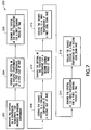
Figure 7 is a block diagram illustrating a first embodiment of a method for improving the light output of a scintillator crystal, in accordance with the present invention; and -
Figure 8 is a block diagram illustrating a second embodiment of a method for improving the light output of a scintillator crystal, in accordance with the present invention. - In accordance with an exemplary embodiment, a method for improving the performance properties of a scintillator crystal, such as a LuAP scintillator crystal, is disclosed, wherein the performance properties include the light output and material uniformity of the LuAP scintillator. This improvement will lead to a better utilization of the downhole tool by allowing for an increase in logging speed and a decrease in tool-to-tool variation by improving the detector resolution, the photopeak shape and the detector-to-detector consistency over existing LuAP scintillators. Referring to
Figure 1 , a plot of Cesium resolution measurements for an LuAP Crystal cube, in accordance with the prior art (i.e. before annealing), is shown.Figure 1 illustrates six Cs137 662 keV peaks for the six cube orientations, wherein the light output was measured with each of the six sides facing the photomultiplier tube (hereinafter "PMT"). As illustrated and understood by one skilled in the art, the plot illustrates a poor level of uniformity as indicated by the scattered pattern of the six measurements. - However, after application of the method for improving the performance properties of the LuAP scintillator to the LuAP Crystal cube, in accordance with the present invention, the performance properties of the LuAP scintillator improves dramatically. Such improvements are illustrated in
Figure 2 , wherein a plot of Cesium resolution measurements for a LuAP Crystal cube after application of the method of the present invention (i.e. post-annealing) is shown. In keeping withFigure 1 ,Figure 2 illustrates the 662 keV peaks for the six cube orientations. As above, the light output was measured with each of the six sides facing the PMT. One skilled in the art will readily recognize that the plot ofFigure 2 illustrates a higher level of light output as indicated by the positions of the peaks being disposed farther to the right hand side of the graph. Also, the more tightly grouped scatter pattern of the six measurements indicates a higher level of uniformity than that shown inFigure 1 . - It should be appreciated that the benefits observed in response to the method of the present invention are at least partially due to the filling of oxygen vacancies in the crystal lattice of the LuAP Crystal lattice. Referring to
Figure 3 , a plot illustrating the results from a series of various annealing treatments performed on a single sample of LuAP material is shown, wherein the different annealing treatments varied in temperature, duration and atmospheric environment. The illustrated annealing treatments are solely for illustrative purposes and are not intended to be limiting of the scope of the present invention. One skilled in the art will readily recognize that numerous alternative annealing techniques are applicable to the present invention. The single sample of LuAP material inFigure 3 was annealed in an atmospheric environment comprised of nitrogen gas with various amount of either hydrogen or oxygen. It should be appreciated that with hydrogen gas present within the annealing environment oxygen will be removed from the crystal lattice (i.e. reducing environment) and with oxygen gas present within the annealing environment oxygen will be added to the crystal lattice (i.e. oxidizing environment). The plot inFigure 3 illustrates that when the LuAP sample is annealed in the oxidizing environment (i.e. oxygen gas present in the annealing environment), the light output increases and resolution improves (i.e. the peak sharpness increases). Additionally,Figure 3 illustrates that when the LuAP sample was annealed in the reducing environment (i.e. hydrogen gas present in the annealing environment), the light output decreased and the resolution degraded (i.e. the peak sharpness decreases). - Referring to
Figure 4 , a plot illustrating the resistivity as a function of temperature for several LuAP samples which have been annealed via application of the method of the present invention is shown. As can be observed by one skilled in the art, when the LuAP sample is annealed within an oxidizing environment, a take-up of oxygen into the crystal lattice of the LuAP occurs. As such, a portion of the oxygen vacancies within the crystal lattice of the sample are filled, thus reducing the concentration of vacancies within the sample material. In response, the LuAP sample that was annealed within an oxidizing environment demonstrates a higher level of resistivity. On the other hand, the LuAP sample that was annealed in the hydrogen environment exhibits a reduction in resistivity indicating an increase in concentration of crystal oxygen vacancies as oxygen is removed from the crystal lattice. It should be appreciated that an oxidizing environment can be established via any method and/or device suitable to the desired end purpose, such as, but not limited to, an introduction of oxygen, Carbon Dioxide and/or Nitrogen Oxides into the environment and/or by saturating an inert gas with water vapor. It should further be appreciated that the use of an oxidizing species, such as oxygen or water vapor, illustrates that the source of the oxidizing gas species is essentially equivalent. As such, the chemical potential of the oxidizing component of the gas mixture is one critical element of the atmosphere in contact with the crystal. For example, some atmospheres where a controlled degree of oxidation can be achieved include a gas composition that may be a mixture of CO/CO2 and/or H2/H2O. The aforementioned atmospheres are not intended to be limiting in scope and are solely for illustrative purposes. - In order to establish an optimum procedure for practicing the method of the present invention, at least two physical phenomena may be considered. First, although the desired LuAP crystal material may be typically disposed in a perovskite phase, the material actually prefers to be in the garnet phase. Thus, annealing the LuAP crystal material to very high temperatures can cause some or all of the LuAP crystal material to convert to the garnet phase and be useless. Second, the LuAP crystal material may be doped with cerium to produce the scintillation light, and although the Ce3+ oxidation state is preferred since it produces the scintillation light, Cerium can exist in either the Ce3+ or Ce4+ oxidation state in the lattice. However, annealing in an oxidizing environment presents the possibility of converting some fraction of the Ce3+ to Ce4+, wherein Ce4+ ions can trap excited electrons and cause undesirable reduction of scintillation light.
- Referring to
Figure 5 , a plot illustrating resolution and light output measurements for a cubed shaped LuAP crystal material that was annealed in an oxidizing environment for different lengths of time is shown. As can be seen, the increase in the light output relative to the increase in annealing time is indicated by the movement of the peaks toward the right hand side of the plot. It should be appreciated that this movement of the peaks toward the right hand side of the plot shows decreased improvement after approximate six (6) hours of annealing time. However, referring toFigure 6 , a plot illustrating the relative light output and resolution versus annealing time is shown which illustrates an improvement following a re-polishing of the detector to remove the garnet phase that grew on the surface of the scintillator sample. As such, the detector performance was still improving with up to 9 hours of annealing. Therefore, it should be appreciated that significant improvements can be made to "as grown" LuAP crystal materials by annealing the "as-grown" LuAP crystal materials in an oxidizing environment, in accordance with the present invention. - It should be appreciated that in one embodiment of the present invention, annealing of LuAP crystals must typically be performed at temperatures greater than 1300°C in order for oxygen to diffuse into the crystal lattice and fill any oxygen vacancies within the crystal. For example, one annealing temperature range for LuAP crystals that produce a positive result includes the temperature range of about 1400°C to about 1500°C. However, for several reasons care may be taken to not allow the annealing temperature to exceed a predetermined threshold limit. First, although the rate at which the oxygen vacancies are filled typically increases with temperature, if the annealing temperature is allowed to be too high (e.g. around 1600°C for LuAP crystals) the garnet phase formation may be accelerated. This is because excessive temperature application has been shown to accelerate the reaction that results in formation of the garnet phase. Because this typically results in a reduced light output and material non-uniformity, one skilled in the art will recognize that is generally undesirable. In addition to temperature, the amount of oxygen disposed within the annealing environment must further be considered when annealing the scintillator crystal. Although at certain oxygen concentration levels the rate at which the oxygen vacancies are filled increases, at higher oxygen concentration levels the conversion rate of Ce+3 to Ce+4, will eventually take place. Hence, the amount of oxygen disposed within the annealing environment must be considered. As above, this is also undesirable due to the reduction in the light output response of the crystal.
- Furthermore, another factor that may be considered when annealing the scintillator crystal involves the rate at which the crystal is heated and/or cooled. This is because if the crystal is heated or cooled too rapidly, the crystal may crack. In fact, one skilled in the art will readily appreciate that the larger the crystal, the slower the heating/cooling rate required may be.
- Referring to
Figure 7 , a block diagram illustrating a first embodiment of amethod 200 for improving the light output of a scintillator crystal is shown and includes disposing the scintillator crystal in a controlled atmosphere that includes a gas or mixture of gases that provide an oxidizing environment, as shown inoperational block 202. For example, one such environment may include Nitrogen comprising at least 0.1 % Oxygen, wherein an Oxygen content of about 3% is preferred for certain conditions. Additionally, other gases suitable to the desired end purpose may be substituted for Nitrogen, such as Helium, Neon, Krypton, Argon, Xenon and/or Radon. Furthermore, any oxidizer suitable to the desired end purpose may be used, such as Oxygen, Carbon Dioxide, Nitrogen Oxides, air and/or water vapor. - Once the controlled atmosphere is established, the scintillation crystal is heated in the oxidizing gas environment, as shown in
operational block 204. It should be appreciated that the crystal may be heated to a temperature which is within the range of about 800°C to about 1200°C, with one acceptable temperature being about 1000°C for certain conditions. One skilled in the art will recognize that numerous alternative heating temperatures are available for use with the present invention. Furthermore, the rate at which the scintillation crystal is heated may be within the range of up to about 10°C/min, with one acceptable heat up rate being about 5°C/min for certain conditions. The scintillation crystal may then be equilibrated or 'soaked' in the oxidizing gas environment at this temperature for a predetermined soaking period of about 0.5 hours to about 2 hours, as shown inoperational block 206. It should be appreciated that the predetermined soaking period may be predicated on certain conditions, such as the size of the scintillation crystal. For example, one acceptable soaking period for a 1cm3 scintillation crystal is about 2 hours, whereas for a larger scintillation crystal the soaking period may be longer than about 2 hours. Additionally, in some situations, this soaking period may not be required, thus allowing the crystal to be heated to a threshold temperature without soaking. - The scintillation crystal may then be heated to a threshold temperature, as shown in
operational block 208, wherein the threshold temperature may be within the range of between about 1200°C to 1650°C and wherein the rate at which the crystal is heated may be about 2°C/min. It should be appreciated that one threshold temperature is about 1450°C for certain conditions. The scintillation crystal may then be 'soaked' in this environment at this threshold temperature for a predetermined soaking period, as shown inoperational block 210, wherein the predetermined soaking period may be within the range of about 1 hour to 24 hours. It should be appreciated that for a 1cm3 scintillation crystal one acceptable threshold temperature is about 1450°C and one acceptable predetermined soaking time period is about 24 hours. At this point, the scintillation crystal is cooled to a temperature range of about 800°C to about 1200°C at a predetermined cool down rate, as shown inoperational block 212, wherein the predetermined cool down rate may be in the range of about 1°C/min to about 10°C/min. As above, under certain conditions, such as for a 1cm3 scintillation crystal, one temperature is about 1000°C and one cool down rate is about 2°C/min. - Once 'cooled down' to the temperature range of about 800°C to about 1200°C, the scintillation crystal may be equilibrated or 'soaked' at this temperature for a predetermined soaking period of time, as shown in
operational block 214, wherein the predetermined soaking period of time may be in the range of about 0.5 hours to about 10 hours. As above, under certain conditions, such as for a 1cm3 scintillation crystal one acceptable soaking period of time is about 2 hours. Additionally, in some situations, this soaking period may not be required, thus allowing the crystal to be cooled to a final temperature without soaking. The scintillation crystal is then cooled to a final temperature, such as room temperature, at a cool down rate in the range of up to 10°C/min, as shown inoperational block 216. Again, for a scintillation crystal of 1cm3, one acceptable cool down rate may be about 5°C/min. It should be appreciated that the heat up rate and/or cool down rate is typically responsive to the size of the crystal being annealed. As such, it is contemplated that any appropriate heat up rate and/or cool down rate may be used so as long as the selected heat up rate and/or cool down rate does not lead to physical damage to the crystal either from thermal shock and/or from an inadvertent phase transition. - Referring to
Figure 8 , a block diagram illustrating a second embodiment of amethod 300 for improving the light output of a scintillator crystal is provided and includes growing a crystal within a predetermined growing environment, as shown inoperational block 302, wherein the crystal may be annealed during the cool down of the grown crystal. Once the crystal has been grown and is at a high temperature, the crystal may be cooled down to the threshold temperature, wherein the threshold temperature may be within the range of between about 1200°C to 1650°C, as shown inoperational block 304. The crystal is then 'soaked' at this threshold temperature in an oxidizing atmosphere for a predetermined soaking period, as shown inoperational block 306, wherein the predetermined soaking period may be within the range of about 1 hour to 24 hours. It should be appreciated that for a 1cm3 scintillation crystal one acceptable threshold temperature is about 1450°C and one acceptable soaking time period is about 24 hours. At this point, the scintillation crystal is cooled to a temperature range of about 800°C to about 1200°C at a cool down rate of about 1°C/min to about 10°C/min, as shown inoperational block 308. As above, under certain conditions, such as for a 1cm3 scintillation crystal, one acceptable temperature is about 1000°C and one acceptable cool down rate is about 2°/min. - Once 'cooled down' to the temperature range of about 800°C to about 1200°C, the scintillation crystal is equilibrated or 'soaked' at the temperature for a predetermined soaking period of time, as shown in
operational block 310, wherein the predetermined soaking period of time may be in the range of about 0.5 hours to about 10 hours. As above, under certain conditions, such as for a 1cm3 scintillation crystal one acceptable predetermined soaking period of time is about 2 hours. The scintillation crystal is then cooled to a final temperature at a cool down rate in the range of up to 10°C/min, as shown inoperational block 312, wherein the final temperature may be about room temperature. Again, for a scintillation crystal of 1cm3, one acceptable cool down rate may be about 5°C/min. It should be appreciated that during the different phases of themethod - Furthermore, it should be appreciated that the LuAP scintillator of the present invention is ideal for use in spectroscopy applications (above ground and down hole applications), such as density measurements, sigma measurement (thermal neutron die-away) and gamma-ray spectroscopy. Moreover, the LuAP scintillator of the present invention has applicability not only in geological based applications, but also other applications as well, such as nuclear radiation applications. In fact, the LuAP scintillator of the present invention may be used in almost any application that employs other types of scintillators, such as NaI, CsI, BGO, GSO, and LSO, including medical, environmental, and homeland security applications.
- The methods of
Figure 7 andFigure 8 may be implemented, in part or in whole, using a controller operating in response to a computer program. In order to perform the prescribed functions and desired processing, as well as the computations therefore (e.g. execution control algorithm(s), the control processes prescribed herein, and the like), the controller may include, but not be limited to, a processor(s), computer(s), memory, storage, register(s), timing, interrupt(s), communication interface(s), and input/output signal interface(s), as well as combination comprising at least one of the foregoing. - As such, the invention may be embodied, in part or in whole, in the form of a computer or controller implemented processes. The invention may also be embodied in the form of computer program code containing instructions embodied in tangible media, such as floppy diskettes, CD-ROMs, hard drives, and/or any other computer-readable medium, wherein when the computer program code is loaded into and executed by a computer or controller, the computer or controller becomes an apparatus for practicing the invention. The invention can also be embodied in the form of computer program code, for example, whether stored in a storage medium, loaded into and/or executed by a computer or controller, or transmitted over some transmission medium, such as over electrical wiring or cabling, through fiber optics, or via electromagnetic radiation, wherein when the computer program code is loaded into and executed by a computer or a controller, the computer or controller becomes an apparatus for practicing the invention. When implemented on a general-purpose microprocessor the computer program code segments may configure the microprocessor to create specific logic circuits.
Claims (19)
- A method for improving the light output and uniformity of a Lutetium Aluminum Perovskite (LuAP) scintillator crystal, the method comprising:disposing the scintillator crystal in a predetermined oxidizing environment (202, 302);annealing the scintillator crystal in said predetermined environment to a threshold temperature at a temperature change rate, wherein the threshold temperature is between about 1200°C to about 1650°C (208, 304);cooling the scintillator crystal in said predetermined environment to a third temperature at a first cool down rate (212, 308);soaking said scintillator crystal in said predetermined environment at the third temperature for a third soaking period (214, 310); andcooling said scintillator crystal to a final temperature (216, 312).
- The method of Claim 1, further comprising:before annealing the scintillator crystal to the threshold temperature, heating the scintillator crystal to a first temperature at a first heat up rate (204); andsoaking the scintillator crystal at said first temperature for a first soaking period (206); andwherein annealing the scintillator crystal in said predetermined environment to a threshold temperature at a temperature change rate comprises heating the scintillator crystal to said threshold temperature at a second heat up rate (208).
- The method of Claim 2, wherein said first temperature is within a range of between 800°C and 1200°C and wherein said first heat up rate is within a range of up to 10°C/min.
- The method of Claim 2, wherein said first soaking period is between 0.5 hours and 2 hours.
- The method of Claim 2, wherein said first temperature is about 1000°C, said first heat up rate is about 5°C/min and said first soaking period of time is about 2 hours.
- The method of Claim 2, wherein said second heat up rate is about 2°C/min.
- The method of Claim 2, wherein the threshold temperature is about 1450°C and said second heat up rate is about 2°C/min.
- The method of Claim 1, further comprising:disposing the scintillator crystal in a predetermined oxidizing environment comprises growing the scintillator crystal in a predetermined growing environment at a growing temperature (302); andwherein annealing the scintillator crystal in said predetermined environment to a threshold temperature at a temperature change rate comprises cooling the scintillator crystal from said growing temperature to said threshold temperature (304).
- The method of Claim 1, wherein annealing the scintillator crystal in said predetermined environment to a threshold temperature comprises soaking the scintillator crystal in said predetermined environment at the threshold temperature for a soaking period of between 1 hour and 24 hours (210).
- The method of Claim 9, wherein said soaking period is about 24 hours.
- The method of Claim 1, whereincooling said scintillator crystal to a final temperature comprises: cooling said scintillator crystal to said final temperature at a second cool down rate (216, 312).
- The method of Claim 11, wherein said third temperature is between 800°C and 1200°C, said first cool down rate is between 1°C/min and 10°C/min and said third soaking period is between 0.5 hours and 10 hours.
- The method of Claim 11, wherein said third temperature is 1000°C, said first cool down rate is 2°C/min and said third soaking period is about 2 hours.
- The method of Claim 11, wherein said final temperature is between about 20°C and about 25°C and said second cool down rate is up to about 10°C/min.
- The method of Claim 11, wherein said final temperature is between 20°C and 25°C and said second cool down rate is about 5°C/min.
- The method of Claim 1, wherein said predetermined environment includes at least 0.1% Oxygen.
- The method of Claim 1, wherein said predetermined environment includes 3% Oxygen.
- The method of Claim 1, wherein said predetermined environment includes at least one of a Nitrogen component, an Oxygen component, a Helium component, a Neon component, a Krypton component, an Argon component, a Xenon component and a Radon component.
- The method of Claim 17, wherein said predetermined environment includes an oxidation/reduction pair, said oxidation/reduction pair including at least one of Carbon Dioxide/Carbon Monoxide, Hydrogen/Water Vapor and Hydrogen/Nitrogen Oxide.
Applications Claiming Priority (2)
| Application Number | Priority Date | Filing Date | Title |
|---|---|---|---|
| US11/563,359 US7591894B2 (en) | 2006-11-27 | 2006-11-27 | LuAP scintillator |
| PCT/US2007/085569 WO2008067272A2 (en) | 2006-11-27 | 2007-11-27 | Luap scintillator |
Publications (2)
| Publication Number | Publication Date |
|---|---|
| EP2087376A2 EP2087376A2 (en) | 2009-08-12 |
| EP2087376B1 true EP2087376B1 (en) | 2016-06-15 |
Family
ID=39427734
Family Applications (1)
| Application Number | Title | Priority Date | Filing Date |
|---|---|---|---|
| EP07871576.0A Not-in-force EP2087376B1 (en) | 2006-11-27 | 2007-11-27 | Luap scintillator |
Country Status (5)
| Country | Link |
|---|---|
| US (1) | US7591894B2 (en) |
| EP (1) | EP2087376B1 (en) |
| JP (1) | JP2010511076A (en) |
| CN (1) | CN101542314B (en) |
| WO (1) | WO2008067272A2 (en) |
Families Citing this family (10)
| Publication number | Priority date | Publication date | Assignee | Title |
|---|---|---|---|---|
| US8536517B2 (en) * | 2008-11-10 | 2013-09-17 | Schlumberger Technology Corporation | Scintillator based radiation detection |
| US8546749B2 (en) * | 2008-11-10 | 2013-10-01 | Schlumberger Technology Corporation | Intrinsic radioactivity in a scintillator as count rate reference |
| SG172388A1 (en) * | 2008-12-29 | 2011-07-28 | Saint Gobain Ceramics | Rare-earth materials, scintillator crystals, and ruggedized scintillator devices incorporating such crystals |
| GB2483023B (en) * | 2009-05-20 | 2014-02-12 | Schlumberger Holdings | Scintillator crystal materials scintillators and subterranean detectors |
| JP5212841B2 (en) * | 2010-03-29 | 2013-06-19 | 日立金属株式会社 | Method for producing fluorescent material |
| US9664800B2 (en) | 2013-07-31 | 2017-05-30 | University Of Tennessee Research Foundation | Laser etched scintillation detector blocks with internally created reflectors |
| US9335426B2 (en) * | 2013-07-31 | 2016-05-10 | University Of Tennessee Research Foundation | Intrinsic reflectors of scintillation detector elements and formation process of intrinsic reflectors |
| JP2016060844A (en) * | 2014-09-18 | 2016-04-25 | 株式会社東芝 | Phosphor, light-emitting device and process for producing phosphor |
| JP2016060845A (en) * | 2014-09-18 | 2016-04-25 | 株式会社東芝 | Phosphor, phosphor manufacturing method, and light emitting device using the same |
| US11628636B2 (en) | 2021-07-07 | 2023-04-18 | United States Of America As Represented By The Administrator Of Nasa | Automated tow/tape placement system |
Family Cites Families (6)
| Publication number | Priority date | Publication date | Assignee | Title |
|---|---|---|---|---|
| US591714A (en) * | 1897-10-12 | Window-screen | ||
| JPS62228187A (en) * | 1985-12-23 | 1987-10-07 | シユラムバ−ガ− オ−バ−シ−ズ ソシエダ アノニマ | Method and device for inspecting underground bed |
| US5057692A (en) * | 1990-06-29 | 1991-10-15 | General Electric Company | High speed, radiation tolerant, CT scintillator system employing garnet structure scintillators |
| US5961714A (en) * | 1996-03-07 | 1999-10-05 | Schlumberger Technology Corporation | Method of growing lutetium aluminum perovskite crystals and apparatus including lutetium aluminum perovskite crystal scintillators |
| US6437336B1 (en) * | 2000-08-15 | 2002-08-20 | Crismatec | Scintillator crystals and their applications and manufacturing process |
| US7141794B2 (en) * | 2004-06-28 | 2006-11-28 | General Electric Company | Scintillator compositions, related processes, and articles of manufacture |
-
2006
- 2006-11-27 US US11/563,359 patent/US7591894B2/en active Active
-
2007
- 2007-11-27 CN CN2007800440122A patent/CN101542314B/en not_active Expired - Fee Related
- 2007-11-27 JP JP2009538531A patent/JP2010511076A/en active Pending
- 2007-11-27 WO PCT/US2007/085569 patent/WO2008067272A2/en not_active Ceased
- 2007-11-27 EP EP07871576.0A patent/EP2087376B1/en not_active Not-in-force
Also Published As
| Publication number | Publication date |
|---|---|
| JP2010511076A (en) | 2010-04-08 |
| US7591894B2 (en) | 2009-09-22 |
| CN101542314B (en) | 2012-11-21 |
| WO2008067272A3 (en) | 2008-08-28 |
| US20080121817A1 (en) | 2008-05-29 |
| WO2008067272A9 (en) | 2008-07-17 |
| CN101542314A (en) | 2009-09-23 |
| EP2087376A2 (en) | 2009-08-12 |
| WO2008067272A2 (en) | 2008-06-05 |
Similar Documents
| Publication | Publication Date | Title |
|---|---|---|
| WO2008067272A2 (en) | Luap scintillator | |
| US8173953B2 (en) | Gain stabilization of gamma-ray scintillation detector | |
| JP2852944B2 (en) | Lutetium orthosilicate single crystal scintillator detector | |
| US5025151A (en) | Lutetium orthosilicate single crystal scintillator detector | |
| EP3602145B1 (en) | Nuclear well logging tool with at least one gamma-ray scintillation detector employing a thallium-based scintillator material | |
| RU2608614C2 (en) | Neutron radiation receiver based on scintillator containing elpasolite intended for use at oil deposits | |
| US9304226B2 (en) | Scintillator-based neutron detector for oilfield applications | |
| US20150323682A1 (en) | Radiation Detection Apparatus Having A Doped Scintillator And A Pulse Shape Analysis Module And A Method Of Using The Same | |
| JPWO2011145651A1 (en) | Neutron beam detector, scintillator for neutron beam detection, and method for discriminating between neutron beam and γ-ray | |
| CN1017281B (en) | Gamma ray spectroscopy and other logging methods and devices | |
| EP3217194B1 (en) | Nanostructured glass ceramic neutron shield for down-hole thermal neutron porosity measurement tools | |
| Hu et al. | Hadron-induced radiation damage in LuAG: Ce scintillating ceramics | |
| Sidletskiy et al. | Gadolinium pyrosilicate single crystals for gamma ray and thermal neutron monitoring | |
| Wu et al. | Effects of Bi3+ codoping on the optical and scintillation properties of CsI: Tl single crystals | |
| Nakajima et al. | Temperature dependence of scintillation properties and pulse shape discrimination between γ-and α-rays in Gd3Al2Ga3O12: Ce scintillator | |
| US5961714A (en) | Method of growing lutetium aluminum perovskite crystals and apparatus including lutetium aluminum perovskite crystal scintillators | |
| JP4512780B2 (en) | Multipurpose radiation environment monitor element | |
| Bartlett et al. | Radiation damage and activation of CdZnTe by intermediate energy neutrons | |
| Park et al. | Radiation hardness analysis of inorganic scintillators irradiated by a 6 MeV electron beam | |
| JP2006300555A (en) | Method and apparatus for logging all stratum | |
| JP2006083325A (en) | Irradiation-induced illuminant and radiation measurement device operating at high temperature | |
| Yin et al. | Decay of Nb94 and Nb94m | |
| Naidu et al. | Isochronal annealing study of neutron induced defects in single and poly crystals of molybdenum | |
| US11513242B1 (en) | Doped semiconductor-based radiation detectors | |
| Chi et al. | Response Function Test of Marine γ-spectrometry with Different Detector Material |
Legal Events
| Date | Code | Title | Description |
|---|---|---|---|
| PUAI | Public reference made under article 153(3) epc to a published international application that has entered the european phase |
Free format text: ORIGINAL CODE: 0009012 |
|
| 17P | Request for examination filed |
Effective date: 20090522 |
|
| AK | Designated contracting states |
Kind code of ref document: A2 Designated state(s): AT BE BG CH CY CZ DE DK EE ES FI FR GB GR HU IE IS IT LI LT LU LV MC MT NL PL PT RO SE SI SK TR |
|
| DAX | Request for extension of the european patent (deleted) | ||
| 17Q | First examination report despatched |
Effective date: 20110504 |
|
| GRAP | Despatch of communication of intention to grant a patent |
Free format text: ORIGINAL CODE: EPIDOSNIGR1 |
|
| INTG | Intention to grant announced |
Effective date: 20160111 |
|
| GRAS | Grant fee paid |
Free format text: ORIGINAL CODE: EPIDOSNIGR3 |
|
| GRAA | (expected) grant |
Free format text: ORIGINAL CODE: 0009210 |
|
| AK | Designated contracting states |
Kind code of ref document: B1 Designated state(s): AT BE BG CH CY CZ DE DK EE ES FI FR GB GR HU IE IS IT LI LT LU LV MC MT NL PL PT RO SE SI SK TR |
|
| REG | Reference to a national code |
Ref country code: CH Ref legal event code: EP Ref country code: GB Ref legal event code: FG4D |
|
| REG | Reference to a national code |
Ref country code: IE Ref legal event code: FG4D |
|
| REG | Reference to a national code |
Ref country code: AT Ref legal event code: REF Ref document number: 806776 Country of ref document: AT Kind code of ref document: T Effective date: 20160715 |
|
| REG | Reference to a national code |
Ref country code: DE Ref legal event code: R096 Ref document number: 602007046694 Country of ref document: DE |
|
| REG | Reference to a national code |
Ref country code: LT Ref legal event code: MG4D |
|
| REG | Reference to a national code |
Ref country code: NL Ref legal event code: MP Effective date: 20160615 |
|
| PG25 | Lapsed in a contracting state [announced via postgrant information from national office to epo] |
Ref country code: FI Free format text: LAPSE BECAUSE OF FAILURE TO SUBMIT A TRANSLATION OF THE DESCRIPTION OR TO PAY THE FEE WITHIN THE PRESCRIBED TIME-LIMIT Effective date: 20160615 Ref country code: LT Free format text: LAPSE BECAUSE OF FAILURE TO SUBMIT A TRANSLATION OF THE DESCRIPTION OR TO PAY THE FEE WITHIN THE PRESCRIBED TIME-LIMIT Effective date: 20160615 |
|
| REG | Reference to a national code |
Ref country code: AT Ref legal event code: MK05 Ref document number: 806776 Country of ref document: AT Kind code of ref document: T Effective date: 20160615 |
|
| PG25 | Lapsed in a contracting state [announced via postgrant information from national office to epo] |
Ref country code: SE Free format text: LAPSE BECAUSE OF FAILURE TO SUBMIT A TRANSLATION OF THE DESCRIPTION OR TO PAY THE FEE WITHIN THE PRESCRIBED TIME-LIMIT Effective date: 20160615 Ref country code: LV Free format text: LAPSE BECAUSE OF FAILURE TO SUBMIT A TRANSLATION OF THE DESCRIPTION OR TO PAY THE FEE WITHIN THE PRESCRIBED TIME-LIMIT Effective date: 20160615 Ref country code: NL Free format text: LAPSE BECAUSE OF FAILURE TO SUBMIT A TRANSLATION OF THE DESCRIPTION OR TO PAY THE FEE WITHIN THE PRESCRIBED TIME-LIMIT Effective date: 20160615 Ref country code: GR Free format text: LAPSE BECAUSE OF FAILURE TO SUBMIT A TRANSLATION OF THE DESCRIPTION OR TO PAY THE FEE WITHIN THE PRESCRIBED TIME-LIMIT Effective date: 20160916 |
|
| PG25 | Lapsed in a contracting state [announced via postgrant information from national office to epo] |
Ref country code: IS Free format text: LAPSE BECAUSE OF FAILURE TO SUBMIT A TRANSLATION OF THE DESCRIPTION OR TO PAY THE FEE WITHIN THE PRESCRIBED TIME-LIMIT Effective date: 20161015 Ref country code: EE Free format text: LAPSE BECAUSE OF FAILURE TO SUBMIT A TRANSLATION OF THE DESCRIPTION OR TO PAY THE FEE WITHIN THE PRESCRIBED TIME-LIMIT Effective date: 20160615 Ref country code: SK Free format text: LAPSE BECAUSE OF FAILURE TO SUBMIT A TRANSLATION OF THE DESCRIPTION OR TO PAY THE FEE WITHIN THE PRESCRIBED TIME-LIMIT Effective date: 20160615 Ref country code: RO Free format text: LAPSE BECAUSE OF FAILURE TO SUBMIT A TRANSLATION OF THE DESCRIPTION OR TO PAY THE FEE WITHIN THE PRESCRIBED TIME-LIMIT Effective date: 20160615 Ref country code: IT Free format text: LAPSE BECAUSE OF FAILURE TO SUBMIT A TRANSLATION OF THE DESCRIPTION OR TO PAY THE FEE WITHIN THE PRESCRIBED TIME-LIMIT Effective date: 20160615 |
|
| PG25 | Lapsed in a contracting state [announced via postgrant information from national office to epo] |
Ref country code: PT Free format text: LAPSE BECAUSE OF FAILURE TO SUBMIT A TRANSLATION OF THE DESCRIPTION OR TO PAY THE FEE WITHIN THE PRESCRIBED TIME-LIMIT Effective date: 20161017 Ref country code: PL Free format text: LAPSE BECAUSE OF FAILURE TO SUBMIT A TRANSLATION OF THE DESCRIPTION OR TO PAY THE FEE WITHIN THE PRESCRIBED TIME-LIMIT Effective date: 20160615 Ref country code: ES Free format text: LAPSE BECAUSE OF FAILURE TO SUBMIT A TRANSLATION OF THE DESCRIPTION OR TO PAY THE FEE WITHIN THE PRESCRIBED TIME-LIMIT Effective date: 20160615 Ref country code: AT Free format text: LAPSE BECAUSE OF FAILURE TO SUBMIT A TRANSLATION OF THE DESCRIPTION OR TO PAY THE FEE WITHIN THE PRESCRIBED TIME-LIMIT Effective date: 20160615 Ref country code: BE Free format text: LAPSE BECAUSE OF FAILURE TO SUBMIT A TRANSLATION OF THE DESCRIPTION OR TO PAY THE FEE WITHIN THE PRESCRIBED TIME-LIMIT Effective date: 20160615 |
|
| REG | Reference to a national code |
Ref country code: DE Ref legal event code: R097 Ref document number: 602007046694 Country of ref document: DE |
|
| PLBE | No opposition filed within time limit |
Free format text: ORIGINAL CODE: 0009261 |
|
| STAA | Information on the status of an ep patent application or granted ep patent |
Free format text: STATUS: NO OPPOSITION FILED WITHIN TIME LIMIT |
|
| 26N | No opposition filed |
Effective date: 20170316 |
|
| PG25 | Lapsed in a contracting state [announced via postgrant information from national office to epo] |
Ref country code: DK Free format text: LAPSE BECAUSE OF FAILURE TO SUBMIT A TRANSLATION OF THE DESCRIPTION OR TO PAY THE FEE WITHIN THE PRESCRIBED TIME-LIMIT Effective date: 20160615 |
|
| REG | Reference to a national code |
Ref country code: CH Ref legal event code: PL |
|
| GBPC | Gb: european patent ceased through non-payment of renewal fee |
Effective date: 20161127 |
|
| PG25 | Lapsed in a contracting state [announced via postgrant information from national office to epo] |
Ref country code: LI Free format text: LAPSE BECAUSE OF NON-PAYMENT OF DUE FEES Effective date: 20161130 Ref country code: CH Free format text: LAPSE BECAUSE OF NON-PAYMENT OF DUE FEES Effective date: 20161130 |
|
| REG | Reference to a national code |
Ref country code: IE Ref legal event code: MM4A |
|
| REG | Reference to a national code |
Ref country code: FR Ref legal event code: ST Effective date: 20170731 |
|
| PG25 | Lapsed in a contracting state [announced via postgrant information from national office to epo] |
Ref country code: SI Free format text: LAPSE BECAUSE OF FAILURE TO SUBMIT A TRANSLATION OF THE DESCRIPTION OR TO PAY THE FEE WITHIN THE PRESCRIBED TIME-LIMIT Effective date: 20160615 |
|
| PG25 | Lapsed in a contracting state [announced via postgrant information from national office to epo] |
Ref country code: LU Free format text: LAPSE BECAUSE OF NON-PAYMENT OF DUE FEES Effective date: 20161130 |
|
| PG25 | Lapsed in a contracting state [announced via postgrant information from national office to epo] |
Ref country code: FR Free format text: LAPSE BECAUSE OF NON-PAYMENT OF DUE FEES Effective date: 20161130 |
|
| PG25 | Lapsed in a contracting state [announced via postgrant information from national office to epo] |
Ref country code: GB Free format text: LAPSE BECAUSE OF NON-PAYMENT OF DUE FEES Effective date: 20161127 Ref country code: IE Free format text: LAPSE BECAUSE OF NON-PAYMENT OF DUE FEES Effective date: 20161127 |
|
| PG25 | Lapsed in a contracting state [announced via postgrant information from national office to epo] |
Ref country code: CY Free format text: LAPSE BECAUSE OF FAILURE TO SUBMIT A TRANSLATION OF THE DESCRIPTION OR TO PAY THE FEE WITHIN THE PRESCRIBED TIME-LIMIT Effective date: 20160615 Ref country code: HU Free format text: LAPSE BECAUSE OF FAILURE TO SUBMIT A TRANSLATION OF THE DESCRIPTION OR TO PAY THE FEE WITHIN THE PRESCRIBED TIME-LIMIT; INVALID AB INITIO Effective date: 20071127 |
|
| PG25 | Lapsed in a contracting state [announced via postgrant information from national office to epo] |
Ref country code: MC Free format text: LAPSE BECAUSE OF FAILURE TO SUBMIT A TRANSLATION OF THE DESCRIPTION OR TO PAY THE FEE WITHIN THE PRESCRIBED TIME-LIMIT Effective date: 20160615 Ref country code: TR Free format text: LAPSE BECAUSE OF FAILURE TO SUBMIT A TRANSLATION OF THE DESCRIPTION OR TO PAY THE FEE WITHIN THE PRESCRIBED TIME-LIMIT Effective date: 20160615 |
|
| PG25 | Lapsed in a contracting state [announced via postgrant information from national office to epo] |
Ref country code: BG Free format text: LAPSE BECAUSE OF FAILURE TO SUBMIT A TRANSLATION OF THE DESCRIPTION OR TO PAY THE FEE WITHIN THE PRESCRIBED TIME-LIMIT Effective date: 20160615 |
|
| PG25 | Lapsed in a contracting state [announced via postgrant information from national office to epo] |
Ref country code: MT Free format text: LAPSE BECAUSE OF NON-PAYMENT OF DUE FEES Effective date: 20161127 |
|
| PGFP | Annual fee paid to national office [announced via postgrant information from national office to epo] |
Ref country code: DE Payment date: 20221004 Year of fee payment: 16 Ref country code: CZ Payment date: 20221116 Year of fee payment: 16 |
|
| REG | Reference to a national code |
Ref country code: DE Ref legal event code: R119 Ref document number: 602007046694 Country of ref document: DE |
|
| PG25 | Lapsed in a contracting state [announced via postgrant information from national office to epo] |
Ref country code: CZ Free format text: LAPSE BECAUSE OF NON-PAYMENT OF DUE FEES Effective date: 20231127 |
|
| PG25 | Lapsed in a contracting state [announced via postgrant information from national office to epo] |
Ref country code: CZ Free format text: LAPSE BECAUSE OF NON-PAYMENT OF DUE FEES Effective date: 20231127 |
|
| PG25 | Lapsed in a contracting state [announced via postgrant information from national office to epo] |
Ref country code: DE Free format text: LAPSE BECAUSE OF NON-PAYMENT OF DUE FEES Effective date: 20240601 |
|
| PG25 | Lapsed in a contracting state [announced via postgrant information from national office to epo] |
Ref country code: DE Free format text: LAPSE BECAUSE OF NON-PAYMENT OF DUE FEES Effective date: 20240601 |