EP2086217A1 - Image processing method - Google Patents
Image processing method Download PDFInfo
- Publication number
- EP2086217A1 EP2086217A1 EP09250237A EP09250237A EP2086217A1 EP 2086217 A1 EP2086217 A1 EP 2086217A1 EP 09250237 A EP09250237 A EP 09250237A EP 09250237 A EP09250237 A EP 09250237A EP 2086217 A1 EP2086217 A1 EP 2086217A1
- Authority
- EP
- European Patent Office
- Prior art keywords
- luminance
- tone curve
- value
- tone
- image
- Prior art date
- Legal status (The legal status is an assumption and is not a legal conclusion. Google has not performed a legal analysis and makes no representation as to the accuracy of the status listed.)
- Granted
Links
- 238000003672 processing method Methods 0.000 title claims description 13
- 238000000034 method Methods 0.000 claims description 35
- 238000003384 imaging method Methods 0.000 claims description 31
- 230000008569 process Effects 0.000 claims description 21
- 230000003247 decreasing effect Effects 0.000 claims description 3
- 238000012545 processing Methods 0.000 description 15
- 238000010586 diagram Methods 0.000 description 13
- 230000006870 function Effects 0.000 description 11
- 230000014509 gene expression Effects 0.000 description 8
- 238000013507 mapping Methods 0.000 description 7
- 230000006835 compression Effects 0.000 description 6
- 238000007906 compression Methods 0.000 description 6
- 238000006243 chemical reaction Methods 0.000 description 4
- 230000008859 change Effects 0.000 description 3
- 239000002131 composite material Substances 0.000 description 2
- 230000005611 electricity Effects 0.000 description 2
- 238000005401 electroluminescence Methods 0.000 description 2
- 238000011156 evaluation Methods 0.000 description 2
- 230000007246 mechanism Effects 0.000 description 2
- 238000012544 monitoring process Methods 0.000 description 2
- 230000003287 optical effect Effects 0.000 description 2
- 238000003825 pressing Methods 0.000 description 2
- 230000005540 biological transmission Effects 0.000 description 1
- 230000015556 catabolic process Effects 0.000 description 1
- 230000000295 complement effect Effects 0.000 description 1
- 238000009264 composting Methods 0.000 description 1
- 238000012790 confirmation Methods 0.000 description 1
- 238000006731 degradation reaction Methods 0.000 description 1
- 230000000694 effects Effects 0.000 description 1
- 239000000284 extract Substances 0.000 description 1
- 238000001914 filtration Methods 0.000 description 1
- 239000004973 liquid crystal related substance Substances 0.000 description 1
- 230000006386 memory function Effects 0.000 description 1
- 229910044991 metal oxide Inorganic materials 0.000 description 1
- 150000004706 metal oxides Chemical class 0.000 description 1
- 230000002265 prevention Effects 0.000 description 1
- 230000008707 rearrangement Effects 0.000 description 1
- 239000004065 semiconductor Substances 0.000 description 1
Images



Classifications
-
- H—ELECTRICITY
- H04—ELECTRIC COMMUNICATION TECHNIQUE
- H04N—PICTORIAL COMMUNICATION, e.g. TELEVISION
- H04N1/00—Scanning, transmission or reproduction of documents or the like, e.g. facsimile transmission; Details thereof
- H04N1/40—Picture signal circuits
- H04N1/407—Control or modification of tonal gradation or of extreme levels, e.g. background level
- H04N1/4072—Control or modification of tonal gradation or of extreme levels, e.g. background level dependent on the contents of the original
- H04N1/4074—Control or modification of tonal gradation or of extreme levels, e.g. background level dependent on the contents of the original using histograms
Definitions
- the present invention relates to an image processor, an image processing method, an image processing program, and an imaging apparatus.
- the luminance of a photographing subject is detected by an exposure controlling section inside the camera, parameters regarding a shutter speed, exposure of an aperture and so on are adjusted according to the luminance detected, and then the image shot by the camera is recorded such that the image has a predetermined tone expression.
- Japanese patent publication numbers 2006-128986 and 2005-130484 disclose various kinds of tone compensation methods.
- a function of an image compensation after shooting here, a tone compensation is often installed.
- the tone curve is an input-output conversion characteristic (function) in a case where a horizontal axis represents input image information and a vertical axis represents output image information. That is, the tone curve is defined as the function which converts a luminance value of an input image to a corresponding luminance value of an output image.
- obtaining the output image (or performing a predetermined compensation) corresponding to the input image by applying to the tone curve is generally called a tone mapping (tone mapping operation).
- An object of the present invention is to provide an image processor in which a calculation load of a CPU is small, a compensation range for an image is large, and a suitable compensation per image is capable of being performed, an image processing method, an image processing program, and an imaging apparatus.
- the present invention provides an image processor comprising: a luminance histogram calculator which calculates a histogram regarding luminance of image data having luminance information; a tone curve generator which generates a tone curve of the image data from the luminance histogram calculated by the luminance histogram calculator; and an image compensator which compensates the image data by the tone curve generated by the tone curve generator to be output image data; wherein the luminance histogram calculator, when a default tone curve is given beforehand, compensates the default tone curve so that a corresponding output value on a tone curve when an average value of a luminance value of the image data calculated from the luminance histogram is taken as an input point becomes a center value of a width of an output value variance range of the default tone curve, and generates a new tone curve.
- the tone curve generator after compensating the default tone curve so that the corresponding output value on the tone curve when the average value of the luminance value of the image' data calculated from the luminance histogram is taken as the input point becomes the center value of the width of the output value variance range of the default tone curve, taking the average value of the luminance value as a border, performs a dividing operation which divides the luminance histogram into two luminance areas of a high luminance side and a low luminance side, and taking a point on the tone curve corresponding to the average value of the luminance value and the center value of the width of the output value variance range as a border and divides the compensated tone curve into two tone curves corresponding to the two luminance areas, and performs as compensation operation which calculates an average value of a luminance value of a luminance histogram in each divided luminance area and compensates each tone curve so that each corresponding output value on each tone curve corresponding to each luminance area when the average value of the luminance value of the luminance histogram
- the tone curve generator performs the tone curve generation operation a predetermined number of times.
- the tone curve generator repeatedly performs the dividing operation and the compensation operation, in a case where entire luminance values are divided by predetermined resolution until an average value of a luminance value becomes a value between divided luminance values which are next to each other, and generates a new tone curve.
- the tone curve generator in a case where entire luminance values are divided by predetermined resolution and an average value of a luminance value becomes a value between divided luminance values which are next to each other in a luminance value area, performs the dividing operation and the compensation operation only in a luminance area in which the average value of the luminance value does not become a value between the divided luminance values which are next to each other, and generates a new tone curve.
- the image processor further comprises: a tone curve compressor which compresses an output luminance value of a tone curve to prevent a tone jump in which a continuity of tone is lost in the tone curve generated by the tone curve generator.
- a tone curve compressor which compresses an output luminance value of a tone curve to prevent a tone jump in which a continuity of tone is lost in the tone curve generated by the tone curve generator.
- the image processor further comprises: a tone curve additional compensator which further compensates a tone curve so that a projection amount of the tone curve is decreased as it gets closer to a center value of an input luminance value.
- a tone curve additional compensator which further compensates a tone curve so that a projection amount of the tone curve is decreased as it gets closer to a center value of an input luminance value.
- the luminance histogram calculator in a case where a luminance histogram of input image data is calculated, uses a reduced image of the input image data.
- the invention provides an image processing method comprising: a luminance calculation process which calculates a histogram regarding luminance of image data having luminance information; a tone curve generation process which generates a tone curve of the image data from the luminance histogram calculated by the luminance calculation process; and an image compensation process which compensates the image data by the tone curve generated by the tone curve generation process to be output image data, wherein the tone curve generation process, when a default tone curve is given beforehand, compensates the default tone curve so that a corresponding output value on a tone curve when an average value of a luminance value of the image data calculated from the luminance histogram is taken as an input point becomes a center value of a width of an output value variance range of the default tone curve, and generates a new tone curve.
- the tone curve generation process after compensating the default tone curve so that a corresponding output value on the tone curve when the average value of the luminance value of image data calculated from the luminance histogram is taken as the input point becomes the center value of the width of the output value variance range of the default tone curve, taking the average value of the luminance value as a border, performs a dividing operation which divides the luminance histogram into two luminance areas of a high luminance side and a low luminance side, and taking a point on the tone curve corresponding to the average value of the luminance value and the center value of the width of the output value variance range as a border and divides the compensated tone curve into two tone curves corresponding to the two luminance areas, and performs a compensation operation which calculates an average value of a luminance value of a luminance histogram in each divided luminance area and compensates each tone curve so that each, corresponding output value on each tone curve corresponding to each luminance area when the average value of the luminance value of the luminance his
- the tone curve generation process performs the tone curve generation operation a predetermined number of times.
- the tone curve generation process repeatedly performs the dividing operation and the compensation operation, in a case where entire luminance values are divided by predetermined resolution, until an average value of a luminance value becomes a value between divided luminance values which are next to each other, and generates a new tone curve.
- the tone curve generation process in a case where entire luminance values are divided by predetermined resolution and an average value of a luminance value becomes a value between divided luminance values which are next to each other in a luminance value area, performs the dividing operation and the compensation operation only in a luminance area in which the average value of the luminance value does not become a value between the divided luminance values which are next.to each other, and generates a new tone curve.
- the invention provides an image processing program which is achieved by a computer to perform an operation in the image processing method according to any one of those methods described above.
- the present invention relates to an image processing which is applied to an imaging apparatus such as a digital camera and so on having a tone compensation function of image data.
- an imaging apparatus such as a digital camera and so on having a tone compensation function of image data.
- the present invention is applied to a digital camera, that is, the imaging apparatus will be explained as the digital camera.
- the present invention solves the above problems in a case where a tone compensation is performed by use of a tone curve.
- the present invention provides an image processor where one tone curve is compensated according to image data, and thereby the image data is compensated, so that a dark part and a light part in the image data are concurrently entered in an expressible tone range and a suitable compensation without incongruity is performed on the image data, an image processing method, an image processing program, and an imaging apparatus.
- the present invention uses one tone curve which is partially compensated according to the image data for a tone compensation, therefore a calculation load is small.
- a compensation range to the image data is large, and the suitable compensation is respectively performed on the image.
- the present invention is good for applying to the imagine apparatus such as the digital camera and so on having the tone compensation function of the image data.
- the imaging apparatus will be explained as the digital camera.
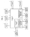
- FIG. 1 illustrates a structural example of hardware of a digital camera as an imaging apparatus to which an image processing of the present invention is applied.
- this digital camera has a controller (CPU) 1, a memory 2, an imaging element 3, a focus lens driver 4, a shutter driver 5, a display 6, a light metering sensor 7, a menu switch 8, a first release switch (RL1SW) 9, a second release switch (RL2SW) 10, an imaging mode switch 11.
- CPU central processing unit
- the controller (CPU) 1 has a control function to control a movement of the camera, and a calculation function to perform various judgments and calculations, a time count (timer) function to count time, and a volatile or a nonvolatile memory area to store various setting values and so on included inside.
- a structure of the controller 1 does not have to be a one-chip CPU structure, and the structure may be a structure which is integrated with an image processing chirp, or may be a structure of a control unit which includes a plurality of CPUs, an external memory and so on.
- the calculation function, or the memory function, or the like is used, and various calculations and controls such as a luminance histogram calculation, a tone curve calculation, an image compensation calculation using the tone curve and so on as described later are performer.
- the light metering sensor 7 is a sensor which detects information corresponding to brightness of a photographing subject.
- the light metering sensor 7 is driven by a control from the controller 1, detects an electric signal corresponding to the brightness of the photographing subject in a specified area or a plurality of areas of an imaging range, and inputs the signal to the controller 1.
- an exclusive light metering sensor a structure which detects brightness using luminance information of imaging data by the imaging element 3 may be provided.
- the first release switch (RL1SW) 9 to image is pressed halfway down to output an ON signal.
- the second release switch (RL2SW) 10 is pressed fully down to output an ON signal.
- the first release switch (RL1SW) 9 and the second release switch (RL2SW) are respectively illustrated as different switches.
- the first release switch (RL1SW) and the second release switch (RL2SW) are structured as the same component, and are a switch which outputs a signal as described above by a difference of an operation (a depth of pressing).
- the focus lens driver 4 performs a movement to focus for imaging (focus drive), and the shutter driver 5 performs a movement to control a light amount (shutter drive).
- the focus lens driver 4 extracts a high-frequency component of the imaging data imaged by the imaging element 3, scans within an adjustment range of the focus lens (in a case of a general shooting mode, a position of the focus lens in the shooting mode is from the closet shooting distance to infinity) while obtaining a so-called focus evaluation value (it is also called an AF (Auto Focus) evaluation value) which is a resource for a focus judgment, and thereby the focus lens driver 4 also has a role of finding the position of the focus lens which is focused.
- the shutter driver 5 is a mechanism to control a transmission amount of light to the imaging element 3.
- An appropriate structure for the shutter driver 5 is selected from among structures such as a structure by a so-called single electronic shutter which is an electrical light amount adjustment mechanism using the imaging element 3, a combined structure of the electronic shutter and a shutter which mechanically opens and closes (there is a shutter structure used for both the shutter and an aperture, and a shutter structure in which the shutter and the aperture are separately provided), a structure by a single mechanical shutter, and so on.
- the display 6 is a display using a liquid crystal, an organic EL (Electro-Luminescence), an LED (Light-Emitting Diode) and so on to display for monitoring as an operation of viewing a photographing subject before, shooting (it is also called a live preview), display for a reproduction of images already shot, and display for a menu, various information, detected data and so on for advance settings of photographing conditions, imaging modes, operation setting selections, tone compensation level.selections and so on.
- a liquid crystal an organic EL (Electro-Luminescence), an LED (Light-Emitting Diode) and so on to display for monitoring as an operation of viewing a photographing subject before, shooting (it is also called a live preview), display for a reproduction of images already shot, and display for a menu, various information, detected data and so on for advance settings of photographing conditions, imaging modes, operation setting selections, tone compensation level.selections and so on.
- the memory 2 is a recorder for storing image data after converting the image data already shot in a predetermined storing format, and is a recording medium such as an internal flash memory, a memory card, a hard disk and so on.
- the imaging element 3 is an element to convert a photographing subject which is incident via a photographing optical system to an electric signal and input into the controller 1, and is structured by a CCD (Charge-Coupled Device) image sensor, or a CMOS (Complementary Metal-Oxide Semiconductor) image sensor or the like.
- the camera naturally has an imaging optical system (lens), which is not illustrated particularly, for example, a single-focus lens, or a multi-focus lens, or a zoom lens or the like.
- the imaging mode SW (switch) 11 is a switch to set settings for selecting. or performing an imaging mode or an image compensation, and may be a single selectable structure (the settings for selecting and performing are set by a plurality of the switch pressings), or may be a structure of a combination with a menu display to set the settings for selecting and performing.
- the menu SW (switch) 8 is a switch to set a switching of the menu display or a general display. After displaying the menu, various settings,: selecting or performing an operation level and the like are performed by use of a back-forth-right-left SW (switch) (not illustrated), a confirmation SW (switch) (not illustrated) and the like, and a general state is returned by the menu SW (switch) 8 after setting.
- a power SW (switch), the back-forth-right-left SW to select and confirm the menu, a zoom SW (switch) to set an imaging range (imaging magnification) (a zooming operation when equipped with a zoom lens) and so on are not illustrated in the drawings and are not explained in detail here.
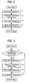
- FIG. 2 illustrates a structural example of an image processor of the present invention.
- the image processor of the present invention has an image size converter 21, a luminance histogram calculator 22, a tone curve generator 23, and an image compensator (tone mapping operator) 24.
- the image size converter 21 converts a size of input image data, when the image data is input.
- the luminance histogram calculator 22 calculates a histogram regarding luminance of the image data in which the size is converted by the image size converter 21.
- the tone curve generator 23 generates a tone curve from the luminance histogram calculated by the luminance histogram calculator 22.
- the image compensator (tone mapping processor) 24 compensates the image data by the tone curve which is generated by the tone curve generator 23 to be output image data.
- the size of the input image data is reduced by the image size converter. 21 and a histogram of the reduced image such as a monitoring image for the display (a live preview image) or the like is generally used, instead of the luminance data of actual input data (that is, the large input image data), so that a calculation amount is reduced when the luminance histogram is calculated and an entire operation is capable of being speeded up.
- a tendency of the luminance histogram is the same as the actual input image data (the large image data), there are few differences in a calculated tone curve (which is compensated by the present invention).
- the compensated tone curve is used for the input image data, and output image data is converted and outputted. Therefore, there is no degradation of image quality and an overall effect of sgeeding-up is large.
- FIG. 3 A processing operation of the digital camera in which the image processor has a structure of FIG. 2 will be explained by use of a flow chart of FIG. 3 .
- step S1 When shooting, various operations are performed on the image data imaged by the imaging element 3 and inputted to the controller 1. At this time, it is judged whether or not a user selects a tone compensation operation by a menu button or the like (step S1).
- a tone mapping operation is performed on the image data by a tone curve which is set beforehand (step S5). After a predetermined operation, the image data is stored in the memory 2, and the shooting operation is finished.
- the size of the image data is converted by the image size converter 21 according to necessary precision in the tone curve generator 24 (step S2).
- a luminance histogram as illustrated in FIG. 4 is calculated by the luminance histogram calculator 22 from the image converted to a suitable size by the image size converter 21 (step S3).
- a conversion to the suitable image size makes it possible to simplify an operation of the luminance histogram calculator 22 and shorten an operation time.
- tone curve generator 23 generates a tone curve based on the luminance histogram calculated by the: luminance histogram calculator 22 (step S4).
- step S5 the tone mapping operation is performed by the tone curve generated by the tone curve generator 23 (step S5), and after a predetermined operation, output image data is stored in the memory 2.
- the tone curve generator 23 generates a suitable tone curve by use of the luminance histogram per image data.
- the tone curve, generator 23 generates the suitable histogram by use of an average value of luminance obtained from the luminance histogram. That is, the tone curve generator 23 compensates the tone curve before the compensation so that a corresponding output value on the tone curve when the average value of the luminance is taken as an input value is set to be in a suitable tone output range, and generates a new tone curve.
- an image (a tone) compensation is performed by use of the new generated tone curve, and thereby a suitable tone compensation per image is performed.
- tone curve generator 23 of the present invention will be described in detail.
- the tone curve generator 23 compensates the default tone curve so that a corresponding output value on a tone curve becomes a center value in a width of the output value variance range of the default tone curve when an average value of a luminance, value of the image data calculated from the luminance histogram is taken as an input value, and generates a new tone curve.
- a default tone curve is given beforehand
- the tone curve generator 23 compensates the default tone curve so that a corresponding output value on a tone curve becomes a center value in a width of the output value variance range of the default tone curve when an average value of a luminance, value of the image data calculated from the luminance histogram is taken as an input value, and generates a new tone curve.
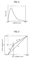
- FIG. 4 and FIG. 5 are explanatory diagrams of operations of the tone curve generator 23 in the first embodiment of the present invention.
- FIG. 4 illustrates an example of a luminance histogram of the image data
- FIG. 5 is an explanatory diagram of a new tone curve generating operation in a case where the luminance histogram of the image data is FIG. 4 .
- the default tone curve as illustrated by a numeral 31 in FIG.5 , is given beforehand.
- An average value of a luminance value of the image data calculated from the luminance histogram of FIG. 4 is illustrated by a numeral A0 in FIG.5 .
- the tone curve generator 23, as illustrated in FIG. 5 compensates the default tone curve 31 so that a corresponding output value on the tone curve becomes a center value H0 of a width of an output value variance range (a width of an output luminance value variance range) y0 when the average value of the luminance value A0 of the image data calculated by the luminance histogram of FIG. 4 is taken as an input value, and generates a new tone curve 32.
- the image is an entirely dark image and the luminance histogram is on a dark part (left) side.
- an average value of a luminance value is not in an area of the luminance histogram where the user intends (mostly in a center part) and is often placed in an imbalanced manner.
- a corresponding point P1 (turning point) on the tone curve 31 when an average value of luminance A0 of the image data calculated from the luminance histogram is taken as an input point on the tone curve 31 is shifted to a center value H0 of a width of an output value variance range (a width of an output luminance value variance range) of the tone curve 31, a new tone curve 32 including two straight lines (tone curves) 33, 34 is generated.
- the default tone curve 31 is a reference tone curve in which an input-output characteristic is linear.
- the turning point becomes P1, and thereby a new tone curve 32 including two straight lines (tone curves) 33, 34 is generated.
- a luminance histogram becomes like FIG. 6 .
- FIG. 4 which is a luminance histogram before the compensation, it is obvious that a shape of an entire luminance histogram moves to a light direction. Therefore, a dark image is brightly-compensated to be closer to a center of a tone expression area.
- the tone curve generator 23 after compensating the default tone curve so that a corresponding output value on the tone curve when an average value of a luminance value of the image data calculated from the luminance histogram is taken as an input value becomes a center value of a width of an output value variance-range of the default tone curve as the first embodiment described above, taking the average value of the luminance value as a border, divides an input luminance area of the tone curve into two luminance areas (input luminance areas) of a high luminance side and a low luminance side, and taking a point on the tone curve corresponding to the average value of the luminance value and a center value of the width of the output value variance range as a border, divides the compensated tone curve into two tone curves corresponding to the two luminance areas (input luminance areas), calculates an average value of an luminance value of the luminance histogram in each divided luminance area (input luminance area), compensates each tone curve so that each corresponding output value on each tone curve
- FIG.7 and FIG. 8 are diagrams to explain operations of the tone curve generator 23 in the second embodiment of the present invention.
- FIG. 7 illustrates a new tone curve 32 of FIG. 5
- FIG. 8 is a diagram to explain an operation where the new tone curve 3 2 of FIG. 5 is further compensated and a new tone curve 35 is generated.
- an input luminance area of the tone curve is divided into two luminance areas (input luminance areas) x1 x2 of a high luminance side and a low luminance side, and taking a point P1 on the tone curve corresponding to the average value of the luminance value A0 and a center value H0 of the width of the output value variance range y0 as a border, the compensated tone curve 32 is divided into two tone curves 33, 34 corresponding to the two luminance areas (input luminance areas) x1, x2.
- each tone 33, 34 is compensated so that corresponding output values 601, 602 on each tone curve 33, 34 corresponding to each luminance area (each input luminance area) x1, x2 when the average values of the luminance values A1, A2 in each luminance area (input luminance area) x1, x2 are taken as input points become center values H1, H2 of each width of output value variance range y1, y2 of the tone curves 33, 34, and a new tone curve 35 is generated.
- an input luminance area of the tone curve is divided into a low luminance side (dark part) x1 and a high luminance side (light part) x2. And then, furthermore, in each divided luminance area (each input luminance area) x1, x2, a luminance histogram per luminance area (input luminance area) x1, x2 is calculated and the average values of the luminance values A1, A2 per luminance area (input luminance area) x1, x2 are calculated.
- tone curves 33, 34 per luminance area (input luminance area) x1, x2 are respectively compensated to be a tone curve 35 (36, 37, 38, 39) as illustrated in FIG. 8 so that obtained average values of the luminance values A1, A2 per area (input luminance area) x1, x2 are input points of the tone curves 33, 34 per luminance area (input luminance area) x1, x2 and corresponding output values 601, 602 on the tone curves 33, 34 are arranged in center values H1, H2 of each width of output value variance range (width of output value variance range) x1, x2.
- a tone curve 35 where an image is brightly tone-expressed in both of the dark part and the light part is calculated. That is, compared with the first embodiment, in the dark part, the image is prevented from not being too brightly expressed, and in the light part, the tone curve is capable of expressing more brightly.
- image data is subdivided, and a luminance average value is calculated per luminance area (input luminance area) calculated by use of the luminance histogram.
- a tone curve is segmentally calculated, and thereby a tone curve which is more suitable for image data to be compensated than that of the first embodiment is generated.
- the tone curve generator 23 taking the average value of the luminance value calculated from the: luminance histogram in each luminance area (each input luminance area) as a border, further divides the input luminance area of the tone curves in each luminance area (each input luminance area) into two luminance areas (input luminance areas) of a high luminance side and a low luminance side, and taking each point on tone curves corresponding to the average value of the luminance value and center values of each width of output value variance range of tone curves calculated from the luminance histogram in each luminance area (each input luminance area) as borders, further divides each tone curve, calculates the average value of the luminance value of the luminance histograms in each divided luminance area (input luminance area), compensates each tone curve so that corresponding output values on each tone curve corresponding to each luminance area (each input luminance area) when the average value of the luminance value of the luminance histograms in each luminance area (input
- FIG. 9 is an explanatory diagram of a processing operation of the tone curve generator 23 in the third embodiment of the present invention. And FIG. 9 explains a further compensation operation of the new tone curve 35 (36, 37, 38, 39) of FIG. 8 and a generation operation of another new tone curve 40.
- a luminance area of the tone curve 33 obtained from the second embodiment is divided into two luminance areas (input luminance area) x3, x4 of a low luminance area and a high luminance area, and taking the point 601 on the tone curve corresponding to the average value of the luminance value A1 and the center value H1 of a width y1 of output value variance range of the tone curve 33, the tone curve 33 is further divided into tone curves 36, 37.
- each tone curve 36, 37 is compensate so that each corresponding value on the tone curves 36, 37 becomes center values H3, H4 of each width of output value variance range y3, y4 of each tone curve 36, 37 when each average value of luminance value A3, A4 is taken as each input point.
- a luminance area of the tone curve 34 obtained from the second embodiment is divided into two luminance areas (input luminance area) x5, x6 of a low luminance area and a high luminance area, and taking the point 602 on the tone curve corresponding to the average value of the luminance value A2 and the center value H2 of a width y2 of output value variance range of the tone curve 34, the tone curve 3 is further divided into tone curves 38, 39.
- FIG. 11 illustrates a flow chart of a particular example of a repeat operation of the tone curve generator 23.
- a hollowing default setting is performed to take an entire luminance histogram as an object (step S11).
- an average value of a luminance value: (input luminance average value) in a specified input range is calculated (step S 12).
- one point of the tone curve is determined so that an output luminance value corresponding to the calculated input luminance average value becomes a center (1/2) of the output range (an output center is set) (step S13).
- a broken line where the determined point is connected with straight lines is a new tone curve (a tone curve is compensated) (step S14).
- an input-output range is reset (step S15). That is, taking the calculated input luminance average value as a border, a next input range (each input luminance range) is set. And taking the output center value as a border, a next output range (a width of output luminance value variance range of the new tone curve (each tone curve)) is determined.
- an end determination is performed (step S16). That is, the end determination is performed by whether all output luminance values to input luminance values corresponding to the resolution set by the default setting are determined or not. When all the output luminance values to the input luminance values corresponding to the resolution set by the default setting are not determined, the operation goes back to the step S12 again, and until all the output luminance values to the input luminance values corresponding to the resolution set by the default setting is determined, the steps S12 to S15 are repeated.
- the tone curve generator 23 of the third embodiment the tone curve 50 per image data, for example, as illustrated in FIG. 10 , so that the tone curve compensation operation is repeated until the luminance output values of the tone curve corresponding to the input luminance values (integers) which are set beforehand on the axis of the entire luminance.
- an image (tone) compensation by use of the generated tone curve 50 an entirely dark image having the histogram as FIG. 4 , is compensated to be an image having the histogram as FIG. 6 which is shifted to a light direction.
- a tone curve 60 as illustrated in FIG. 13 is eventually generated.
- peaks in the dark part and the light part of the luminance histogram are close to a center part where a tone is expressible, and this means that a compensation is performed so that main parts in the dark part and the light part are close to the center part where the tone is expressible.
- the tone curve generation operation in the embodiments of the first to the third described above
- it is ideal to perform a rearrangement operation of the tone curve (the tone curve generation operation in the embodiments of the first to the third described above) until output luminance values of the tone curves corresponding to input luminance values which are set beforehand on the axis of the entire luminance are rearranged.
- an operation load and an operation time are considered, and the image compensation may be performed by use of a calculated tone curve when the operation is arbitrarily stopped by a predetermined number of times and a predetermined number of divides.
- the tone curve generator 23 repeatedly performs the predetermined number of times a dividing operation of the luminance area (input luminance area) and the tone curve in the third embodiment and a compensation operation of the tone curve, and generates a new tone curve.
- the tone curve generator 23 when the entire luminance values are divided by the predetermined resolution, repeatedly performs the divide operation of the luminance area (input luminance area) and the tone curve in the third embodiment, and the compensation operation of the tone curve until an average value of the luminance value becomes a value between the divided luminance values which are next to each other, and generates a new tone curve.
- the tone curve generator 23 in the third embodiment, in a case where an average value of a luminance area in a luminance area becomes a value between divided luminance values which are next to each other, the dividing operation of the luminance value area (input luminance area) and the tone curve, and the compensation operation of the tone curve, only on an area where the average value of the luminance value does not become a value between divided luminance values which are next to each other, and generates a new tone curve.
- the tone curve generation operation is finished at this stage (the fifth embodiment), or the tone curve generation operation (compensation operation) is continuously performed on only luminance areas (input luminance areas) x3, x5, x6 except the luminance area (input luminance area) x4.
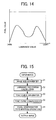
- FIG. 15 illustrates a structural example of an image processor of a seventh embodiment of the present invention.
- a tone curve compressor 25 is further provided in the tone curve generated by the tone curve generator 23 to prevent a tone jump.
- the tone curve compressor 25 compresses an output luminance value of the tone curve.
- the tone curve generated in any one of the first to the sixth embodiments is a suitable tone curve in a case where the output luminance range is lager enough than the input luminance range, however there is an additional problem in a case where the tone curve above is actually applied to a general digital camera and is performed.
- the general digital camera 8-bit input image data is expressed by 8-bit output image data, therefore in a case where the tone curve is rearranged by use of procedures of the first to the sixth embodiments and the image compensation is performed by use of the new tone curve, it is known that a phenomenon called atone jump occurs when the tone curve generated has an abrupt (a steeply-inclined) part.
- the tone jump is the phenomenon where a continuity of the tone is lost in an output image of an image output by use of the tone curve.
- a specific example will be explained.
- luminance values of two consecutive points on the input luminance axis are smoothly changed to be 30, 31.
- output luminance values 30, 31 in each pixel value become respectively 40, 50
- there is no data between 41 and 49 as the output luminance value there is no data between 41 and 49 as the output luminance value.
- an abrupt tone change is generated. Therefore, as the output image, the continuity of the tone is lost and is not smooth.
- the tone jump is a problem which should be avoided in the image output by use of the tone curve.
- the tone curve compressor 25 compresses the output luminance value of the tone curve to prevent the tone jump in the tone curve generated by the tone curve generator 23.
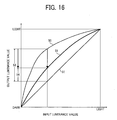
- the tone curve in the first to the sixth embodiments for example, the tone curve 50 illustrated in FIG. 10 is transformed into a tone curve 51 as illustrated in FIG. 16 . That is, by compressing a curve to be controlled, the tone curve generated in the first to the sixth embodiments, for example, the tone curve 50 in FIG. 10 , without sacrificing its characteristic, the tone jump is prevented.
- the tone curve generated in the first to the sixth embodiments, for example; the tone curve 50 in FIG. 10 is compressed, for example, a difference between an output luminance value of the tone curve 50 and an output luminance value of the tone curve 31 is taken as a distance 53 in an input value.
- a following is performed.
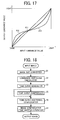
- a tone curve resulting from the compensation for example, as illustrated in FIG. 17 , taking a reference tone curve (a reference straight line where: an input luminance value directly corresponds to an output luminance value by 1:1) as a border, is a curve comprising curves 912, 913 which are arranged both above and below the reference straight line, the tone curve resulting from the compensation especially woks effectively in the compression operation above.
- the curve 912 works to lighten an image
- the curve 913 works to darken an image.
- the compression operation above is performed based on a distance from the reference straight line, therefore the intersection point 911 does not move in a result of the compression operation, and a problem such that a place supposed to be darkened is lightened in the compression operation does not occur.
- a compression rate, in a predetermined image, in a case where there is a steep inclination in the tone curve in which the tone compensation operation is performed, may be set so that the tone jump does not occur, and is not limited to a numeric value, 40 %
- FIG. 18 illustrates a structural example of an image processor of an eighth embodiment of the present invention.
- a tone curve additional compensator 26 is further provided in the eighth embodiment of the present invention.
- the tone curve additional compensator 26 further compensates the tone curve obtained by any one of the first to the seventh embodiments so that a projection amount of the tone curve to the tone curve 31 is decreased as the tone curve is closer to a center value of the input luminance value of image data.
- a quadratic curve 70 as illustrated in FIG. 19 .
- the projection amount of the tone curve is small, and the projection amount of the tone curve is large in both end parts (dark and light parts) in the vicinity of the center value of the input luminance value.
- a shape of a tone curve after compensating by the filter above becomes a shape as illustrated in FIG. 20 in which the projection amount of a middle luminance part 1101 is prevented.
- an additional compensation operation by the tone curve additional compensator 26 is performed on the tone curve compressed by the tone curve compressor 25.
- the eighth embodiment of the present invention does not have to be provided with the tone curve compressor 25, in this case, as illustrated by a dashed line in FIG. 18 , the additional compensation operation by the tone curve additional compensator 26 is performed on the tone curve generated by the tone curve generator 23.
- An image to be compensated is an image against a photographer's intention, therefore it is possible to easily achieve a tone compensation according to an image where the photographer's intention is reflected and the tone jump does not easily occur by performing the processing of the present invention which has been described.
- the present invention is achieved without a special hardware as described later. Compared with the method of calculating tone curves per area, respectively compensating the tone curves and composting compensated images, a calculating amount is small and calculating speed is fast enough.
- the image processor of the present invention in the example of FIG. 1 , is achieved by the controller (CPU) 1.
- the program which is achieved by, for example, the controller (CPU) 1, to perform the operations in the image processor to carry out the present invention described above, is stored on computer-readable recording media such as a hard disk, a floppy disk, a CD-ROM (Compact Disk Read Only Memory), an MO (Magneto-Optical disk), a DVD (Digital Versatile Disk) and so on, and is carried out by being read out from the recording medium by the computer.
- this program is able to be distributed by the recording medium on which the program is stored, and via a network of the internet and so on.
- an imaging apparatus to which the image processing of the present invention is applied has been explained as a digital camera, however the -imaging apparatus to which the image processing of the present invention is applied is not limited to the digital camera.
- one tone curve is partially compensated according to an image (luminance histogram of image data) and is used for a tone compensation, therefore a calculation load of a CPU is small Furthermore a compensation range to the image is large and a suitable compensation is performed per image.
Landscapes
- Engineering & Computer Science (AREA)
- Multimedia (AREA)
- Signal Processing (AREA)
- Facsimile Image Signal Circuits (AREA)
- Image Processing (AREA)
- Studio Devices (AREA)
Abstract
Description
- The present invention relates to an image processor, an image processing method, an image processing program, and an imaging apparatus.
- When an image is shot by a digital camera, the luminance of a photographing subject is detected by an exposure controlling section inside the camera, parameters regarding a shutter speed, exposure of an aperture and so on are adjusted according to the luminance detected, and then the image shot by the camera is recorded such that the image has a predetermined tone expression.
- However, not all images have tone expressions according to a photographer's intention. For example, in as case where an error in an exposure control happens for some reasons and so on, a photographer may wish to compensate tone expressions of the images shot after shooting.
- For example, Japanese patent publication numbers
2006-128986 2005-130484 3992177 - As for the digital cameras described above, it is possible for a user to manually compensate a tone of an image according to a user's desire and a shooting intention while confirming a compensation result.
- A similar function, namely a technique using a tone curve, is already known as an application software for a personal computer (hereinafter, it is called PC). Here, the tone curve is an input-output conversion characteristic (function) in a case where a horizontal axis represents input image information and a vertical axis represents output image information. That is, the tone curve is defined as the function which converts a luminance value of an input image to a corresponding luminance value of an output image. Thus, obtaining the output image (or performing a predetermined compensation) corresponding to the input image by applying to the tone curve is generally called a tone mapping (tone mapping operation).
- There have been known methods such as- a method of compensation by shifting the tone curve to obtain a suitable tone expression of an entire image plane while displaying the tone curve on a PC screen (a method for shifting entirely a tone curve), and a tone compensation method where an image is divided into areas based on various conditions, a tone curve is obtained per area, each image per area is compensated to have a suitable tone, and each image per area after the tone compensation is combined to be one composite image.
- As for the former method, there is a problem that a range capable of compensating is small because a compensation is performed to shift entirely one tone curve. For example, when a dark part is brightly-compensated to be entered in a tone where the dark part is expressible, there is no tone in a light part (so-called overexposure). Therefore, as a result, it is only a balance adjustment of either the dark part or the light part and how much of it is entered in an expressible part.
- On the other hand, in the latter method, an image plane is divided into areas, a suitable tone curve is generated for each image per area, each image data per area is respectively compensated, and compensated divided area images are combined to obtain one composite image. Because of this procedure described above, a range of the compensation is large. However, in a case where this operation is performed inside of a digital camera in which especially a space or an electricity consumption is small, an exclusive IC (Integrated Circuit) for a calculation, an ultrahigh-performance CPU (Central Processing Unit) and so on are needed. Therefore, there are high possibilities of not avoiding a cost rise and of being over the electricity consumption. In addition, if these calculations are performed in a control CPU for a general digital camera, it takes a significantly long calculation time (time needed for a compensation) and thereby there is a problem of unusability.
- An object of the present invention is to provide an image processor in which a calculation load of a CPU is small, a compensation range for an image is large, and a suitable compensation per image is capable of being performed, an image processing method, an image processing program, and an imaging apparatus.
- In order to achieve the above object, the present invention provides an image processor comprising: a luminance histogram calculator which calculates a histogram regarding luminance of image data having luminance information; a tone curve generator which generates a tone curve of the image data from the luminance histogram calculated by the luminance histogram calculator; and an image compensator which compensates the image data by the tone curve generated by the tone curve generator to be output image data; wherein the luminance histogram calculator, when a default tone curve is given beforehand, compensates the default tone curve so that a corresponding output value on a tone curve when an average value of a luminance value of the image data calculated from the luminance histogram is taken as an input point becomes a center value of a width of an output value variance range of the default tone curve, and generates a new tone curve.
- Preferably, the tone curve generator, after compensating the default tone curve so that the corresponding output value on the tone curve when the average value of the luminance value of the image' data calculated from the luminance histogram is taken as the input point becomes the center value of the width of the output value variance range of the default tone curve, taking the average value of the luminance value as a border, performs a dividing operation which divides the luminance histogram into two luminance areas of a high luminance side and a low luminance side, and taking a point on the tone curve corresponding to the average value of the luminance value and the center value of the width of the output value variance range as a border and divides the compensated tone curve into two tone curves corresponding to the two luminance areas, and performs as compensation operation which calculates an average value of a luminance value of a luminance histogram in each divided luminance area and compensates each tone curve so that each corresponding output value on each tone curve corresponding to each luminance area when the average value of the luminance value of the luminance histogram in each luminance area is taken as an input point becomes a center value of a width of an output value variance range of each tone curve, and performs a tone curve generation operation which generates a new tone curve.
- Preferably, the tone curve generator performs the tone curve generation operation a predetermined number of times.
- Preferably, the tone curve generator repeatedly performs the dividing operation and the compensation operation, in a case where entire luminance values are divided by predetermined resolution until an average value of a luminance value becomes a value between divided luminance values which are next to each other, and generates a new tone curve.
- Preferably, the tone curve generator, in a case where entire luminance values are divided by predetermined resolution and an average value of a luminance value becomes a value between divided luminance values which are next to each other in a luminance value area, performs the dividing operation and the compensation operation only in a luminance area in which the average value of the luminance value does not become a value between the divided luminance values which are next to each other, and generates a new tone curve.
- Preferably, the image processor further comprises: a tone curve compressor which compresses an output luminance value of a tone curve to prevent a tone jump in which a continuity of tone is lost in the tone curve generated by the tone curve generator.
- Preferably, the image processor further comprises: a tone curve additional compensator which further compensates a tone curve so that a projection amount of the tone curve is decreased as it gets closer to a center value of an input luminance value.
- Preferably, the luminance histogram calculator, in a case where a luminance histogram of input image data is calculated, uses a reduced image of the input image data.
- In addition, the invention provides an image processing method comprising: a luminance calculation process which calculates a histogram regarding luminance of image data having luminance information; a tone curve generation process which generates a tone curve of the image data from the luminance histogram calculated by the luminance calculation process; and an image compensation process which compensates the image data by the tone curve generated by the tone curve generation process to be output image data, wherein the tone curve generation process, when a default tone curve is given beforehand, compensates the default tone curve so that a corresponding output value on a tone curve when an average value of a luminance value of the image data calculated from the luminance histogram is taken as an input point becomes a center value of a width of an output value variance range of the default tone curve, and generates a new tone curve.
- Preferably, the tone curve generation process, after compensating the default tone curve so that a corresponding output value on the tone curve when the average value of the luminance value of image data calculated from the luminance histogram is taken as the input point becomes the center value of the width of the output value variance range of the default tone curve, taking the average value of the luminance value as a border, performs a dividing operation which divides the luminance histogram into two luminance areas of a high luminance side and a low luminance side, and taking a point on the tone curve corresponding to the average value of the luminance value and the center value of the width of the output value variance range as a border and divides the compensated tone curve into two tone curves corresponding to the two luminance areas, and performs a compensation operation which calculates an average value of a luminance value of a luminance histogram in each divided luminance area and compensates each tone curve so that each, corresponding output value on each tone curve corresponding to each luminance area when the average value of the luminance value of the luminance histogram in each luminance area is taken as an input point becomes a center value of a width of an output value variance range of each tone curve, and performs a tone curve generation operation which generates a new tone curve.
- Preferably, the tone curve generation process performs the tone curve generation operation a predetermined number of times.
- Preferably, the tone curve generation process repeatedly performs the dividing operation and the compensation operation, in a case where entire luminance values are divided by predetermined resolution, until an average value of a luminance value becomes a value between divided luminance values which are next to each other, and generates a new tone curve.
- Preferably, the tone curve generation process, in a case where entire luminance values are divided by predetermined resolution and an average value of a luminance value becomes a value between divided luminance values which are next to each other in a luminance value area, performs the dividing operation and the compensation operation only in a luminance area in which the average value of the luminance value does not become a value between the divided luminance values which are next.to each other, and generates a new tone curve.
- The invention provides an image processing program which is achieved by a computer to perform an operation in the image processing method according to any one of those methods described above.
- The invention provides an imaging apparatus which uses the image processor according to any one of those image processors described above. The invention will now be described by way of non-limiting examples with reference to the accompanying drawings, in which:
-
-
FIG. 1 illustrates.a structural example of hardware of a digital camera as an imaging apparatus to which an imaging process of the present invention is applied. -
FIG. 2 illustrates a structural example of an image processor of the present invention. -
FIG. 3 is a flow chart which explains a processing operation of a digital camera in a case where an image processor is structured to beFIG. 2 described above. -
FIG. 4 is an explanatory diagram which explains a processing operation of a tone curve generator in a first embodiment of the present invention. -
FIG. 5 is an explanatory diagram which explains another processing operation of the tone curve generator in the first embodiment of the present invention. -
FIG. 6 illustrates a luminance histogram when an image is compensated by a newly applied tone curve which is generated by the tone curve generator of the present invention. -
FIG. 7 is an explanatory diagram which explains a processing operation of a tone curve generator in a second embodiment of the present invention. -
FIG. 8 is an explanatory diagram which explains another processing operation of the tone curve generator in the second embodiment of the present invention. -
FIG. 9 is an explanatory diagram which explains a processing operation of a tone curve generator in a third embodiment of the present invention. -
FIG. 10 illustrates a tone curve which is finally generated. -
FIG. 11 is a flow chart which illustrates a specific example of a repeat operation of the tone curve generator. -
FIG. 12 is a diagram which illustrates another example of a tone curve generation operation. -
FIG. 13 is a diagram which illustrates still another example of the tone curve generation operation. -
FIG. 14 is a diagram which illustrates yet still another example of the tone curve generation operation. -
FIG. 15 illustrates a structural example of an image processor of a seventh embodiment of the present invention. -
FIG. 16 illustrates a tone curve which is compressed by a tone curve compressor of the seventh embodiment of the present invention. -
FIG. 17 illustrates an example of a compensation result. -
FIG. 18 illustrates a structural example of an image processor of an eighth embodiment of the present invention. -
FIG. 19 illustrates a quadratic curve in order to prevent a tone jump. -
FIG. 20 illustrates an example of a tone curve where the tone jump is prevented. - The present invention relates to an image processing which is applied to an imaging apparatus such as a digital camera and so on having a tone compensation function of image data. Here, assume that the present invention is applied to a digital camera, that is, the imaging apparatus will be explained as the digital camera.
- The present invention solves the above problems in a case where a tone compensation is performed by use of a tone curve. The present invention provides an image processor where one tone curve is compensated according to image data, and thereby the image data is compensated, so that a dark part and a light part in the image data are concurrently entered in an expressible tone range and a suitable compensation without incongruity is performed on the image data, an image processing method, an image processing program, and an imaging apparatus.
- The present invention uses one tone curve which is partially compensated according to the image data for a tone compensation, therefore a calculation load is small. In addition, compared with a method where one tone curve is entirely sifted, a compensation range to the image data is large, and the suitable compensation is respectively performed on the image.
- Therefore, the present invention is good for applying to the imagine apparatus such as the digital camera and so on having the tone compensation function of the image data. Hereinafter, assume that the present invention is applied to a digital camera, that is, the imaging apparatus will be explained as the digital camera.
-
FIG. 1 illustrates a structural example of hardware of a digital camera as an imaging apparatus to which an image processing of the present invention is applied. - Referring to
FIG. 1 , this digital camera has a controller (CPU) 1, a memory 2, animaging element 3, afocus lens driver 4, ashutter driver 5, a display 6, a light metering sensor 7, amenu switch 8, a first release switch (RL1SW) 9, a second release switch (RL2SW) 10, animaging mode switch 11. - Here, the controller (CPU) 1 has a control function to control a movement of the camera, and a calculation function to perform various judgments and calculations, a time count (timer) function to count time, and a volatile or a nonvolatile memory area to store various setting values and so on included inside. A structure of the controller 1 does not have to be a one-chip CPU structure, and the structure may be a structure which is integrated with an image processing chirp, or may be a structure of a control unit which includes a plurality of CPUs, an external memory and so on. In this controller 1, the calculation function, or the memory function, or the like is used, and various calculations and controls such as a luminance histogram calculation, a tone curve calculation, an image compensation calculation using the tone curve and so on as described later are performer.
- The light metering sensor 7 is a sensor which detects information corresponding to brightness of a photographing subject. The light metering sensor 7 is driven by a control from the controller 1, detects an electric signal corresponding to the brightness of the photographing subject in a specified area or a plurality of areas of an imaging range, and inputs the signal to the controller 1. Instead of there being provided an exclusive light metering sensor, a structure which detects brightness using luminance information of imaging data by the
imaging element 3 may be provided. - The first release switch (RL1SW) 9 to image is pressed halfway down to output an ON signal. The second release switch (RL2SW) 10 is pressed fully down to output an ON signal. In
FIG. 1 , the first release switch (RL1SW) 9 and the second release switch (RL2SW) are respectively illustrated as different switches. However, in a general hardware structure, the first release switch (RL1SW) and the second release switch (RL2SW) are structured as the same component, and are a switch which outputs a signal as described above by a difference of an operation (a depth of pressing). - The
focus lens driver 4 performs a movement to focus for imaging (focus drive), and theshutter driver 5 performs a movement to control a light amount (shutter drive). Thefocus lens driver 4 extracts a high-frequency component of the imaging data imaged by theimaging element 3, scans within an adjustment range of the focus lens (in a case of a general shooting mode, a position of the focus lens in the shooting mode is from the closet shooting distance to infinity) while obtaining a so-called focus evaluation value (it is also called an AF (Auto Focus) evaluation value) which is a resource for a focus judgment, and thereby thefocus lens driver 4 also has a role of finding the position of the focus lens which is focused. Theshutter driver 5 is a mechanism to control a transmission amount of light to theimaging element 3. An appropriate structure for theshutter driver 5 is selected from among structures such as a structure by a so-called single electronic shutter which is an electrical light amount adjustment mechanism using theimaging element 3, a combined structure of the electronic shutter and a shutter which mechanically opens and closes (there is a shutter structure used for both the shutter and an aperture, and a shutter structure in which the shutter and the aperture are separately provided), a structure by a single mechanical shutter, and so on. - The display 6 is a display using a liquid crystal, an organic EL (Electro-Luminescence), an LED (Light-Emitting Diode) and so on to display for monitoring as an operation of viewing a photographing subject before, shooting (it is also called a live preview), display for a reproduction of images already shot, and display for a menu, various information, detected data and so on for advance settings of photographing conditions, imaging modes, operation setting selections, tone compensation level.selections and so on.
- The memory 2 is a recorder for storing image data after converting the image data already shot in a predetermined storing format, and is a recording medium such as an internal flash memory, a memory card, a hard disk and so on.
- The
imaging element 3 is an element to convert a photographing subject which is incident via a photographing optical system to an electric signal and input into the controller 1, and is structured by a CCD (Charge-Coupled Device) image sensor, or a CMOS (Complementary Metal-Oxide Semiconductor) image sensor or the like. The camera naturally has an imaging optical system (lens), which is not illustrated particularly, for example, a single-focus lens, or a multi-focus lens, or a zoom lens or the like. - The imaging mode SW (switch) 11 is a switch to set settings for selecting. or performing an imaging mode or an image compensation, and may be a single selectable structure (the settings for selecting and performing are set by a plurality of the switch pressings), or may be a structure of a combination with a menu display to set the settings for selecting and performing.
- The menu SW (switch) 8 is a switch to set a switching of the menu display or a general display. After displaying the menu, various settings,: selecting or performing an operation level and the like are performed by use of a back-forth-right-left SW (switch) (not illustrated), a confirmation SW (switch) (not illustrated) and the like, and a general state is returned by the menu SW (switch) 8 after setting.
- A power SW (switch), the back-forth-right-left SW to select and confirm the menu, a zoom SW (switch) to set an imaging range (imaging magnification) (a zooming operation when equipped with a zoom lens) and so on are not illustrated in the drawings and are not explained in detail here.
-
FIG. 2 illustrates a structural example of an image processor of the present invention. Referring toFIG. 2 , the image processor of the present invention has animage size converter 21, aluminance histogram calculator 22, atone curve generator 23, and an image compensator (tone mapping operator) 24. Theimage size converter 21 converts a size of input image data, when the image data is input. Theluminance histogram calculator 22 calculates a histogram regarding luminance of the image data in which the size is converted by theimage size converter 21. Thetone curve generator 23 generates a tone curve from the luminance histogram calculated by theluminance histogram calculator 22. The image compensator (tone mapping processor) 24 compensates the image data by the tone curve which is generated by thetone curve generator 23 to be output image data. - The
image size converter 21, in a case where input image data is small enough, is able to directly give the input image data to theluminance histogram calculator 22 without performing its function. That is, in this case, theimage converter 21 is not needed, and theluminance histogram calculator 22 directly calculates a histogram regarding the luminance of the input image data. - However, a size of the input image data (image data which is imaged) is actually large. Therefore, the size of the input image data is reduced by the image size converter. 21 and a histogram of the reduced image such as a monitoring image for the display (a live preview image) or the like is generally used, instead of the luminance data of actual input data (that is, the large input image data), so that a calculation amount is reduced when the luminance histogram is calculated and an entire operation is capable of being speeded up. In a case where the reduced image data is used, a tendency of the luminance histogram is the same as the actual input image data (the large image data), there are few differences in a calculated tone curve (which is compensated by the present invention). And in a case where the tone mapping (an image conversion/compensation is performed by use of a tone curve) is performed, the compensated tone curve is used for the input image data, and output image data is converted and outputted. Therefore, there is no degradation of image quality and an overall effect of sgeeding-up is large.
- A processing operation of the digital camera in which the image processor has a structure of
FIG. 2 will be explained by use of a flow chart ofFIG. 3 . - When power of the camera is on and a release button is pressed, after a focus operation by a light metering and an AF scanning, and the like, the camera starts shooting by a shutter operation.
- When shooting, various operations are performed on the image data imaged by the
imaging element 3 and inputted to the controller 1. At this time, it is judged whether or not a user selects a tone compensation operation by a menu button or the like (step S1). - When the tone compensation operation is not selected, a tone mapping operation is performed on the image data by a tone curve which is set beforehand (step S5). After a predetermined operation, the image data is stored in the memory 2, and the shooting operation is finished.
- Here, if a reproduction button is pressed, image data which is shot and stored is displayed on the display 6. And at this time, assume that a tone expression of the reproduced image is against a user's intention. In this case, at the step S1, the tone compensation operation is selected by the user with the menu button, operations of steps S2 to S5 are performed.
- That is, when a size of the input image data is large, the size of the image data is converted by the
image size converter 21 according to necessary precision in the tone curve generator 24 (step S2). - Next, a luminance histogram as illustrated in
FIG. 4 is calculated by theluminance histogram calculator 22 from the image converted to a suitable size by the image size converter 21 (step S3). At this time, as described above, a conversion to the suitable image size makes it possible to simplify an operation of theluminance histogram calculator 22 and shorten an operation time. - And the
tone curve generator 23 generates a tone curve based on the luminance histogram calculated by the: luminance histogram calculator 22 (step S4). - And then, the tone mapping operation is performed by the tone curve generated by the tone curve generator 23 (step S5), and after a predetermined operation, output image data is stored in the memory 2.
- By the way, in the present invention, the
tone curve generator 23 generates a suitable tone curve by use of the luminance histogram per image data. In particular, the tone curve,generator 23 generates the suitable histogram by use of an average value of luminance obtained from the luminance histogram. That is, thetone curve generator 23 compensates the tone curve before the compensation so that a corresponding output value on the tone curve when the average value of the luminance is taken as an input value is set to be in a suitable tone output range, and generates a new tone curve. Thus, an image (a tone) compensation is performed by use of the new generated tone curve, and thereby a suitable tone compensation per image is performed. - Hereinafter, the
tone curve generator 23 of the present invention will be described in detail. - In a first embodiment of the present invention, when a default tone curve is given beforehand, the
tone curve generator 23 compensates the default tone curve so that a corresponding output value on a tone curve becomes a center value in a width of the output value variance range of the default tone curve when an average value of a luminance, value of the image data calculated from the luminance histogram is taken as an input value, and generates a new tone curve. The above-described is a characteristic of the first embodiment of the present invention. -
FIG. 4 and FIG. 5 are explanatory diagrams of operations of thetone curve generator 23 in the first embodiment of the present invention.FIG. 4 illustrates an example of a luminance histogram of the image data, andFIG. 5 is an explanatory diagram of a new tone curve generating operation in a case where the luminance histogram of the image data isFIG. 4 . - The default tone curve, as illustrated by a numeral 31 in
FIG.5 , is given beforehand. An average value of a luminance value of the image data calculated from the luminance histogram ofFIG. 4 is illustrated by a numeral A0 inFIG.5 . Thetone curve generator 23, as illustrated inFIG. 5 , compensates thedefault tone curve 31 so that a corresponding output value on the tone curve becomes a center value H0 of a width of an output value variance range (a width of an output luminance value variance range) y0 when the average value of the luminance value A0 of the image data calculated by the luminance histogram ofFIG. 4 is taken as an input value, and generates anew tone curve 32. - That is, in a case where the luminance histogram of the image data is an example as illustrated in
FIG. 4 , the image is an entirely dark image and the luminance histogram is on a dark part (left) side. Generally, in a case of an image which is desired to compensate a tone expression, as the example illustrated inFIG. 4 , an average value of a luminance value is not in an area of the luminance histogram where the user intends (mostly in a center part) and is often placed in an imbalanced manner. - In an example of
FIG. 5 , by an operation that a corresponding point P1 (turning point) on thetone curve 31 when an average value of luminance A0 of the image data calculated from the luminance histogram is taken as an input point on thetone curve 31 is shifted to a center value H0 of a width of an output value variance range (a width of an output luminance value variance range) of thetone curve 31, anew tone curve 32 including two straight lines (tone curves) 33, 34 is generated. Here, thedefault tone curve 31 is a reference tone curve in which an input-output characteristic is linear. And in a case where the average value of the luminance value of the image data is taken as the input point, the turning point becomes P1, and thereby anew tone curve 32 including two straight lines (tone curves) 33, 34 is generated. - In a case where an image is compensated by applying the new tone curve 32 (33, 34) as generated above, a luminance histogram becomes like
FIG. 6 . Compared withFIG. 4 which is a luminance histogram before the compensation, it is obvious that a shape of an entire luminance histogram moves to a light direction. Therefore, a dark image is brightly-compensated to be closer to a center of a tone expression area. - In a second embodiment of the present invention, the tone curve generator 23, after compensating the default tone curve so that a corresponding output value on the tone curve when an average value of a luminance value of the image data calculated from the luminance histogram is taken as an input value becomes a center value of a width of an output value variance-range of the default tone curve as the first embodiment described above, taking the average value of the luminance value as a border, divides an input luminance area of the tone curve into two luminance areas (input luminance areas) of a high luminance side and a low luminance side, and taking a point on the tone curve corresponding to the average value of the luminance value and a center value of the width of the output value variance range as a border, divides the compensated tone curve into two tone curves corresponding to the two luminance areas (input luminance areas), calculates an average value of an luminance value of the luminance histogram in each divided luminance area (input luminance area), compensates each tone curve so that each corresponding output value on each tone curve corresponding to each luminance area (each input luminance area) when the average value of the luminance value of the luminance histogram in each luminance area (input luminance area) is taken as an input point becomes a center value of the width of the output value variance range of each tone curve, and generates a new tone curve. The above-described is a characteristic of the second embodiment of the present invention.
-
FIG.7 andFIG. 8 are diagrams to explain operations of thetone curve generator 23 in the second embodiment of the present invention.FIG. 7 illustrates anew tone curve 32 ofFIG. 5 , andFIG. 8 is a diagram to explain an operation where thenew tone curve 3 2 ofFIG. 5 is further compensated and anew tone curve 35 is generated. - Referring to
FIG. 7 andFIG. 8 , in the second embodiment of the present invention, taking an average value of the luminance value A0 of the image data calculated from the luminance histogram ofFIG. 4 as a border, an input luminance area of the tone curve is divided into two luminance areas (input luminance areas) x1 x2 of a high luminance side and a low luminance side, and taking a point P1 on the tone curve corresponding to the average value of the luminance value A0 and a center value H0 of the width of the output value variance range y0 as a border, the compensatedtone curve 32 is divided into two tone curves 33, 34 corresponding to the two luminance areas (input luminance areas) x1, x2. And the average values of the luminance values A1, A2 of the luminance histogram in each divided luminance area (input luminance areas) x1, x2 are calculated. And then, eachtone corresponding output values tone curve new tone curve 35 is generated. - That is, in the second embodiment of the present invention, firstly, after performing the operation explained in the first embodiment, further taking the average value of the luminance value A0 of the image data calculated from the luminance histogram as a border, as illustrated in
FIG. 7 , an input luminance area of the tone curve is divided into a low luminance side (dark part) x1 and a high luminance side (light part) x2. And then, furthermore, in each divided luminance area (each input luminance area) x1, x2, a luminance histogram per luminance area (input luminance area) x1, x2 is calculated and the average values of the luminance values A1, A2 per luminance area (input luminance area) x1, x2 are calculated. And the tone curves 33, 34 per luminance area (input luminance area) x1, x2 are respectively compensated to be a tone curve 35 (36, 37, 38, 39) as illustrated inFIG. 8 so that obtained average values of the luminance values A1, A2 per area (input luminance area) x1, x2 are input points of the tone curves 33, 34 per luminance area (input luminance area) x1, x2 andcorresponding output values - In the second embodiment of the present invention, compared with the reference tone curve 31 (1:1 straight line in which there is no turning point and no input-output conversion), as a result, a
tone curve 35 where an image is brightly tone-expressed in both of the dark part and the light part is calculated. That is, compared with the first embodiment, in the dark part, the image is prevented from not being too brightly expressed, and in the light part, the tone curve is capable of expressing more brightly. Compared with the first embodiment, image data is subdivided, and a luminance average value is calculated per luminance area (input luminance area) calculated by use of the luminance histogram. Thus, a tone curve is segmentally calculated, and thereby a tone curve which is more suitable for image data to be compensated than that of the first embodiment is generated. - In a third embodiment of the present invention, the
tone curve generator 23, taking the average value of the luminance value calculated from the: luminance histogram in each luminance area (each input luminance area) as a border, further divides the input luminance area of the tone curves in each luminance area (each input luminance area) into two luminance areas (input luminance areas) of a high luminance side and a low luminance side, and taking each point on tone curves corresponding to the average value of the luminance value and center values of each width of output value variance range of tone curves calculated from the luminance histogram in each luminance area (each input luminance area) as borders, further divides each tone curve, calculates the average value of the luminance value of the luminance histograms in each divided luminance area (input luminance area), compensates each tone curve so that corresponding output values on each tone curve corresponding to each luminance area (each input luminance area) when the average value of the luminance value of the luminance histograms in each luminance area (input luminance area) are taken as input points become center values of each width of output value variance ranges of the tone curves, and generates a new tone curve. The above-described is a characteristic of the third embodiment of the present invention. -
FIG. 9 is an explanatory diagram of a processing operation of thetone curve generator 23 in the third embodiment of the present invention. AndFIG. 9 explains a further compensation operation of the new tone curve 35 (36, 37, 38, 39) ofFIG. 8 and a generation operation of anothernew tone curve 40. - Referring to
FIG. 9 , in the third embodiment of the present invention, for example, firstly, taking the average value of the luminance value A1 calculated from the luminance histogram in the luminance area (input luminance area) x1 as a border, a luminance area of thetone curve 33 obtained from the second embodiment is divided into two luminance areas (input luminance area) x3, x4 of a low luminance area and a high luminance area, and taking thepoint 601 on the tone curve corresponding to the average value of the luminance value A1 and the center value H1 of a width y1 of output value variance range of thetone curve 33, thetone curve 33 is further divided into tone curves 36, 37. Then, average values of luminance values A3, A4, of luminance histograms in each divided luminance area (input luminance, area) x3, x4 are calculated, and eachtone curve tone curve tone curve 34 obtained from the second embodiment is divided into two luminance areas (input luminance area) x5, x6 of a low luminance area and a high luminance area, and taking thepoint 602 on the tone curve corresponding to the average value of the luminance value A2 and the center value H2 of a width y2 of output value variance range of thetone curve 34, thetone curve 3 is further divided into tone curves 38, 39. Then, average values of luminance values A5, A6 of luminance histograms in each divided luminance area (input luminance area) x5, x6 are calculated, and eachtone curve tone curve new tone curve 40 is generated. - By repeating the above operations until output values of output luminance values corresponding to input luminance values (integers) which are set beforehand on an axis of an entire luminance are rearranged, for example, a
tone curve 50 per image data as illustrated inFIG. 10 is eventually generated. -
FIG. 11 illustrates a flow chart of a particular example of a repeat operation of thetone curve generator 23. - Referring to
FIG. 11 ; firstly, a hollowing default setting is performed to take an entire luminance histogram as an object (step S11). - 1) an input range -(input luminance area) : defined as a minimum value and a maximum value of input luminance. For example, an input minimum value = 0, and an input maximum value = 255.
- 2) an output range (a width of output luminance variance range of the default tone curve): defined as a minimum value and a maximum value of output luminance of the default tone curve. For example, an input minimum value =0, and an input maximum value = 255
- 3) in addition to the above input range and output range, the average value of the luminance value is specified. For example, in a case where the input range has 256 tones, if the resolution has 256 tones, the output luminance values corresponding to entire input luminance values are calculated.
- After the above default setting, an average value of a luminance value: (input luminance average value) in a specified input range is calculated (step S 12).
- And one point of the tone curve is determined so that an output luminance value corresponding to the calculated input luminance average value becomes a center (1/2) of the output range (an output center is set) (step S13).
- And then, a broken line where the determined point is connected with straight lines is a new tone curve (a tone curve is compensated) (step S14).
- Next, an input-output range is reset (step S15). That is, taking the calculated input luminance average value as a border, a next input range (each input luminance range) is set. And taking the output center value as a border, a next output range (a width of output luminance value variance range of the new tone curve (each tone curve)) is determined.
- Next, an end determination is performed (step S16). That is, the end determination is performed by whether all output luminance values to input luminance values corresponding to the resolution set by the default setting are determined or not. When all the output luminance values to the input luminance values corresponding to the resolution set by the default setting are not determined, the operation goes back to the step S12 again, and until all the output luminance values to the input luminance values corresponding to the resolution set by the default setting is determined, the steps S12 to S15 are repeated.
- As described above, by the
tone curve generator 23 of the third embodiment, thetone curve 50 per image data, for example, as illustrated inFIG. 10 , so that the tone curve compensation operation is repeated until the luminance output values of the tone curve corresponding to the input luminance values (integers) which are set beforehand on the axis of the entire luminance. As a result of performing an image (tone) compensation by use of the generatedtone curve 50, an entirely dark image having the histogram asFIG. 4 , is compensated to be an image having the histogram asFIG. 6 which is shifted to a light direction. - As illustrated in
FIG. 12 , in a case where image data has peak values respectively in the dark part and the light part of the luminance histogram, atone curve 60 as illustrated inFIG. 13 is eventually generated. And as a result of an eventual image (tone) compensation, as illustrated inFIG. 14 , peaks in the dark part and the light part of the luminance histogram are close to a center part where a tone is expressible, and this means that a compensation is performed so that main parts in the dark part and the light part are close to the center part where the tone is expressible. - In addition, it is ideal to perform a rearrangement operation of the tone curve (the tone curve generation operation in the embodiments of the first to the third described above) until output luminance values of the tone curves corresponding to input luminance values which are set beforehand on the axis of the entire luminance are rearranged. However, an operation load and an operation time are considered, and the image compensation may be performed by use of a calculated tone curve when the operation is arbitrarily stopped by a predetermined number of times and a predetermined number of divides.
- That is, as a fourth embodiment of the present invention, the
tone curve generator 23 repeatedly performs the predetermined number of times a dividing operation of the luminance area (input luminance area) and the tone curve in the third embodiment and a compensation operation of the tone curve, and generates a new tone curve. - As a fifth embodiment of the present invention, the
tone curve generator 23, when the entire luminance values are divided by the predetermined resolution, repeatedly performs the divide operation of the luminance area (input luminance area) and the tone curve in the third embodiment, and the compensation operation of the tone curve until an average value of the luminance value becomes a value between the divided luminance values which are next to each other, and generates a new tone curve. - As a sixth embodiment of the present invention, the
tone curve generator 23, in the third embodiment, in a case where an average value of a luminance area in a luminance area becomes a value between divided luminance values which are next to each other, the dividing operation of the luminance value area (input luminance area) and the tone curve, and the compensation operation of the tone curve, only on an area where the average value of the luminance value does not become a value between divided luminance values which are next to each other, and generates a new tone curve. - In particular, in an operation illustrated in
FIG.9 , for example, in a case where the average values A1 and A0 of the luminance values of the luminance histogram are next to each other, that is, in a luminance area (input luminance area) x4, in a case where an average value of a luminance value is a value between the divided luminance values which are next to each other, the tone curve generation operation is finished at this stage (the fifth embodiment), or the tone curve generation operation (compensation operation) is continuously performed on only luminance areas (input luminance areas) x3, x5, x6 except the luminance area (input luminance area) x4. -
FIG. 15 illustrates a structural example of an image processor of a seventh embodiment of the present invention. Referring toFIG. 15 , in the seventh embodiment, in the tone curve generated by thetone curve generator 23 to prevent a tone jump, atone curve compressor 25 is further provided. Thetone curve compressor 25 compresses an output luminance value of the tone curve. - That is, the tone curve generated in any one of the first to the sixth embodiments is a suitable tone curve in a case where the output luminance range is lager enough than the input luminance range, however there is an additional problem in a case where the tone curve above is actually applied to a general digital camera and is performed. In the general digital camera, 8-bit input image data is expressed by 8-bit output image data, therefore in a case where the tone curve is rearranged by use of procedures of the first to the sixth embodiments and the image compensation is performed by use of the new tone curve, it is known that a phenomenon called atone jump occurs when the tone curve generated has an abrupt (a steeply-inclined) part. The tone jump is the phenomenon where a continuity of the tone is lost in an output image of an image output by use of the tone curve. A specific example will be explained. For example, in a case where both input and output data are expressed by 8-bit, assume that luminance values of two consecutive points on the input luminance axis are smoothly changed to be 30, 31. Here, as a result of the image output by use of the tone curve, assume that output luminance values 30, 31 in each pixel value become respectively 40, 50 In the image of this output result, there is no data between 41 and 49 as the output luminance value. In this case, between the two points where the luminance values are supposed to be smoothly changed, an abrupt tone change is generated. Therefore, as the output image, the continuity of the tone is lost and is not smooth. The tone jump is a problem which should be avoided in the image output by use of the tone curve.
- Therefore, in the seventh embodiment of the present invention, the
tone curve compressor 25 compresses the output luminance value of the tone curve to prevent the tone jump in the tone curve generated by thetone curve generator 23. In particular, the tone curve in the first to the sixth embodiments, for example, thetone curve 50 illustrated inFIG. 10 is transformed into atone curve 51 as illustrated inFIG. 16 . That is, by compressing a curve to be controlled, the tone curve generated in the first to the sixth embodiments, for example, thetone curve 50 inFIG. 10 , without sacrificing its characteristic, the tone jump is prevented. In a case where the tone curve generated in the first to the sixth embodiments, for example; thetone curve 50 inFIG. 10 is compressed, for example, a difference between an output luminance value of thetone curve 50 and an output luminance value of thetone curve 31 is taken as adistance 53 in an input value. When compressing the input luminance value to 40%, a following is performed. - 1) A
distance 54 is calculated by multiplying thisdistance 53 by 0.4. - 2) An output value which is placed above the
distance 54 is calculated from the output luminance value of thetone curve 31. - 3) 1), 2) above are performed on the entire input luminance values.
By performing above 1) to 3), a new tone curve which is compressed to 40% is obtained. - In the compression operation above, in a case where a tone curve resulting from the compensation, for example, as illustrated in
FIG. 17 , taking a reference tone curve (a reference straight line where: an input luminance value directly corresponds to an output luminance value by 1:1) as a border, is acurve comprising curves intersection point 911 as a border, thecurve 912 works to lighten an image, and thecurve 913 works to darken an image. The compression operation above is performed based on a distance from the reference straight line, therefore theintersection point 911 does not move in a result of the compression operation, and a problem such that a place supposed to be darkened is lightened in the compression operation does not occur. - A compression rate, in a predetermined image, in a case where there is a steep inclination in the tone curve in which the tone compensation operation is performed, may be set so that the tone jump does not occur, and is not limited to a numeric value, 40 %
- In addition,
FIG. 18 illustrates a structural example of an image processor of an eighth embodiment of the present invention. Referring toFIG. 18 , in the eighth embodiment of the present invention; a tone curveadditional compensator 26 is further provided. The tone curveadditional compensator 26 further compensates the tone curve obtained by any one of the first to the seventh embodiments so that a projection amount of the tone curve to thetone curve 31 is decreased as the tone curve is closer to a center value of the input luminance value of image data. - By further provided the above tone curve
additional compensator 26, a further prevention of the tone jump is performed. - That is, in a general tone expression, it is known that the tone jump is more noticeable in a middle luminance part than in extremely dark and light luminance parts. In the eighth embodiment of the present invention, to solve this problem, a filter to prevent a projection amount of the tone curve as it gets closer to the middle luminance part in a compensated tone curve is applied.
- Specifically, it is possible to use a
quadratic curve 70 as illustrated inFIG. 19 . In a quadratic curve, the closer to a center, the more moderate an inclination is. Using this characteristic, by filtering with a quadratic curve, the projection amount of the tone curve is small, and the projection amount of the tone curve is large in both end parts (dark and light parts) in the vicinity of the center value of the input luminance value. By this method, it is comparatively easy to prevent an abrupt tone curve change in the middle luminance value, and to allow the tone curve change in the dark and light parts. A shape of a tone curve after compensating by the filter above, becomes a shape as illustrated inFIG. 20 in which the projection amount of amiddle luminance part 1101 is prevented. - In a structural example of
FIG. 18 , an additional compensation operation by the tone curveadditional compensator 26 is performed on the tone curve compressed by thetone curve compressor 25. However, the eighth embodiment of the present invention does not have to be provided with thetone curve compressor 25, in this case, as illustrated by a dashed line inFIG. 18 , the additional compensation operation by the tone curveadditional compensator 26 is performed on the tone curve generated by thetone curve generator 23. - An image to be compensated is an image against a photographer's intention, therefore it is possible to easily achieve a tone compensation according to an image where the photographer's intention is reflected and the tone jump does not easily occur by performing the processing of the present invention which has been described.
- Additionally, it is possible for the present invention to be achieved without a special hardware as described later. Compared with the method of calculating tone curves per area, respectively compensating the tone curves and composting compensated images, a calculating amount is small and calculating speed is fast enough.
- As described above, the image processor of the present invention, in the example of
FIG. 1 , is achieved by the controller (CPU) 1. - And, as for the image processor and the operations in the image processing method as explained in each embodiment to carry out the present invention, in the example of
FIG. 1 , it is possible to be provided as a program (image processing program) which is achieved by the controller (CPU) 1. - In addition, the program, which is achieved by, for example, the controller (CPU) 1, to perform the operations in the image processor to carry out the present invention described above, is stored on computer-readable recording media such as a hard disk, a floppy disk, a CD-ROM (Compact Disk Read Only Memory), an MO (Magneto-Optical disk), a DVD (Digital Versatile Disk) and so on, and is carried out by being read out from the recording medium by the computer. And this program is able to be distributed by the recording medium on which the program is stored, and via a network of the internet and so on.
- In the explanation above, an imaging apparatus to which the image processing of the present invention is applied has been explained as a digital camera, however the -imaging apparatus to which the image processing of the present invention is applied is not limited to the digital camera.
- According to the embodiments of the present invention, one tone curve is partially compensated according to an image (luminance histogram of image data) and is used for a tone compensation, therefore a calculation load of a CPU is small Furthermore a compensation range to the image is large and a suitable compensation is performed per image.
- Although the present invention has been described in terms of exemplary embodiments, it is not limited thereto. It should be appreciated that variations may be made in the embodiments described by persons skilled in the art without departing from the scope of the present invention as defined by the following claims.
- The present application is based on and priority from Japanese patent application number
2008-019201, filed 30 January, 2008
Claims (15)
- An image processor comprising:a luminance histogram calculator (22) which calculates a histogram regarding luminance of image data having luminance information;a tone curve generator (23) which generates a tone curve of the image data from the luminance histogram calculated by the luminance histogram calculator (22); andan image compensator (24) which compensates the image data by the tone curve generated by the tone curve generator (23) to be output image data; whereinthe luminance histogram calculator (22), when a default tone curve (31) is given beforehand; compensates the default tone curve (31) so that a corresponding output value on a tone curve when an average value of a luminance value of the image data calculated from the luminance histogram is taken as an input point becomes a center value of a width of an output value variance range of the default tone curve (31), and generates a new tone curve.
- The image processor according to claim 1, wherein the tone curve generator (23), after compensating the default tone curve (31) so that the corresponding output value on the tone curve when the average value of the luminance value of the image data calculated from the luminance histogram is taken as the input point becomes the center value of the width of the output value variance range of the default tone curve (31), taking the average value of the luminance value as a border, performs a dividing operation which divides the luminance histogram into two luminance areas of a high luminance side and a low luminance side, and taking a point on the tone curve corresponding to the average value of the luminance value and the center value of the width of the output value variance range as a border and divides the compensated tone curve into two tone curves corresponding to the two luminance areas, and performs a compensation operation which calculates an average value of a luminance value of a luminance histogram in each divided luminance area and compensates each tone curve so that each corresponding output value on each tone curve corresponding to each luminance area when the average value of the luminance value of the luminance histogram in each luminance area is taken as an input point becomes a center value of a width of an output value variance range of each tone curve, and performs a tone curve generation operation which generates a new tone curve.
- The image processor according to claim 2, wherein the tone curve generator (23) performs the tone curve generation operation a predetermined number of times.
- The image processor according to claim 2, wherein the tone curve generator (23) repeatedly performs the dividing operation and the compensation operation, in a case where entire luminance values are divided by predetermined resolution until an average value of a luminance value becomes a value between divided luminance values which are next to each other, and generates a new tone curve.
- The image processor according to claim 2, wherein the tone curve generator (23), in a case where entire luminance values are divided by predetermined resolution and an average value of a luminance value becomes a value between divided luminance values which are next to each other in a luminance value area, performs the divide operation and the compensation operation only in a luminance area in which the average value of the luminance value does not become a value between the divided luminance values which are next to each other, and generates a new tone curve.
- The image processor according to any one of claims 1 to 5, further comprising:a tone curve compressor (25) which compresses an output luminance value of a tone curve to prevent a tone jump in which a continuity of tone is lost in the tone curve generated by the tone curve generator (23).
- The image processor according to any one of claims 1 to 5, further comprising:a tone curve additional compensator (26) which further compensates a tone curve so that a projection amount of the tone curve is decreased as it gets closer to a center value of an input luminance value.
- The image processor according to any one of claims 1 to 7, wherein the luminance histogram calculator (22), in a case where a luminance histogram of input image data is calculated, uses a reduced image of the input image data.
- A image processing method comprising:a luminance calculation process which calculates a histogram regarding luminance of image data having luminance information;a tone curve generation process which generates a tone curve of the image data from the luminance histogram calculated by the luminance calculation process; andan image compensation process which compensates the image data by the tone curve generated by the tone curve generation process to be output image data, wherein
the tone curve generation process, when a default tone curve (31) is given beforehand, compensates the default tone curve (31) so that a corresponding output value on a tone curve when an average value of a luminance value of the image data calculated from the luminance histogram is taken as an input point becomes a center value of a width of an output value variance range of the default tone curve (31), and generates a new tone curve. - The image processing method according to claim 9, wherein the tone curve generation process, after compensating the default tone curve (31) so that a corresponding output value on the tone curve when the average value of the luminance value of image data calculated from the luminance histogram is taken as the input point becomes the center value of the width of the output value variance range of the default tone curve (31), taking the average value of the luminance value as a border, performs a dividing operation which divides the luminance histogram into two luminance areas of a high luminance side and a low luminance side, and taking a point on the tone curve corresponding to the average value of the luminance value and the center value of the width of the output value variance range as a border and divides the compensated tone curve into two tone curves corresponding to the two luminance areas, and performs a compensation operation which calculates an average value of a luminance value of a luminance histogram in each divided luminance area and compensates each tone curve so that each corresponding output value on each tone curve corresponding to each luminance area when the average value of the luminance value of the luminance histogram in each luminance area is taken as an input point becomes a center value of a width of an output value variance range of each tone curve, and performs a tone curve generation operation which generates a new tone curve.
- The image processing method according to claim 10, wherein the tone curve generation process performs the tone curve generation operation a predetermined number of times.
- The image processing method according to claim 10, wherein the tone curve generation process repeatedly performs the dividing operation and the compensation operation, in a case where entire luminance values are divided by predetermined resolution, until an average value of a luminance value becomes a value between divided luminance values which are next to each other, and generates a new tone curve.
- The image processing method according to claim 10, wherein the tone curve generation process, in a case where entire luminance values are divided by predetermined resolution and an average value of a luminance value becomes a value between divided luminance values which are next to each other in a luminance value area, performs the divide operation and the compensation operation only in a luminance area in which the average value of the luminance value does not become a value between the divided luminance values which are next to each other, and generates a new tone curve.
- In image processing program which, when executed by a computer system, instructs the system to perform the image processing method according to any one of claims 9 to 13.
- An imaging apparatus which uses the image processor according to any one of claims 1 to 8.
Applications Claiming Priority (1)
| Application Number | Priority Date | Filing Date | Title |
|---|---|---|---|
| JP2008019201A JP4982399B2 (en) | 2008-01-30 | 2008-01-30 | Image processing apparatus, image processing method, image processing program, and imaging apparatus |
Publications (2)
| Publication Number | Publication Date |
|---|---|
| EP2086217A1 true EP2086217A1 (en) | 2009-08-05 |
| EP2086217B1 EP2086217B1 (en) | 2018-01-10 |
Family
ID=40548518
Family Applications (1)
| Application Number | Title | Priority Date | Filing Date |
|---|---|---|---|
| EP09250237.6A Ceased EP2086217B1 (en) | 2008-01-30 | 2009-01-29 | Image processing method |
Country Status (2)
| Country | Link |
|---|---|
| EP (1) | EP2086217B1 (en) |
| JP (1) | JP4982399B2 (en) |
Cited By (3)
| Publication number | Priority date | Publication date | Assignee | Title |
|---|---|---|---|---|
| CN103109306A (en) * | 2010-09-24 | 2013-05-15 | 英特尔公司 | A brightness enhancement method, system and apparatus for low power architectures |
| CN104412299A (en) * | 2012-06-28 | 2015-03-11 | 夏普株式会社 | Image processing device and recording medium |
| EP3068123A1 (en) * | 2015-03-09 | 2016-09-14 | Omron Corporation | Image generator and image generation method |
Families Citing this family (5)
| Publication number | Priority date | Publication date | Assignee | Title |
|---|---|---|---|---|
| JP6286874B2 (en) * | 2013-05-31 | 2018-03-07 | 株式会社ニコン | Image processing apparatus and image processing program |
| JP2015011585A (en) | 2013-06-28 | 2015-01-19 | 株式会社リコー | Image processing apparatus, image forming apparatus, image forming system, image processing method, and program |
| CN113628106B (en) | 2020-05-08 | 2025-01-28 | 华为技术有限公司 | Image dynamic range processing method and device |
| JP7574110B2 (en) * | 2021-03-10 | 2024-10-28 | 株式会社フジタ | IMAGE PROCESSING APPARATUS, IMAGE PROCESSING METHOD, AND IMAGE PROCESSING PROGRAM |
| JP2023054476A (en) * | 2021-10-04 | 2023-04-14 | 株式会社モルフォ | Image processing device and image processing method |
Citations (6)
| Publication number | Priority date | Publication date | Assignee | Title |
|---|---|---|---|---|
| DE4309878A1 (en) * | 1992-04-06 | 1993-11-04 | Hell Ag Linotype | Image gradation analysis and correction using image segment histograms |
| EP0723364A2 (en) * | 1995-01-17 | 1996-07-24 | AT&T Corp. | Real-time image enhancement techniques |
| US20030002736A1 (en) | 2001-06-14 | 2003-01-02 | Kazutaka Maruoka | Automatic tone correction apparatus, automatic tone correction method, and automatic tone correction program storage mediums |
| US20030174216A1 (en) * | 2002-03-15 | 2003-09-18 | Canon Kabushiki Kaisha | Image processing apparatus, image processing system, image processing method, storage medium, and program |
| EP1377029A2 (en) * | 2002-06-24 | 2004-01-02 | Eastman Kodak Company | Enhancing the tonal characteristics of digital images |
| US20060056688A1 (en) * | 2004-09-14 | 2006-03-16 | Tetsuya Toyoda | Image processing apparatus, image recording apparatus, and image processing method |
Family Cites Families (3)
| Publication number | Priority date | Publication date | Assignee | Title |
|---|---|---|---|---|
| JP4069333B2 (en) * | 1996-11-13 | 2008-04-02 | セイコーエプソン株式会社 | Image processing apparatus, image processing method, and medium on which image processing program is recorded |
| JP2005077950A (en) * | 2003-09-02 | 2005-03-24 | Fujitsu General Ltd | Histogram control image quality correction circuit |
| JP4372747B2 (en) * | 2005-01-25 | 2009-11-25 | シャープ株式会社 | Luminance level conversion device, luminance level conversion method, solid-state imaging device, luminance level conversion program, and recording medium |
-
2008
- 2008-01-30 JP JP2008019201A patent/JP4982399B2/en not_active Expired - Fee Related
-
2009
- 2009-01-29 EP EP09250237.6A patent/EP2086217B1/en not_active Ceased
Patent Citations (6)
| Publication number | Priority date | Publication date | Assignee | Title |
|---|---|---|---|---|
| DE4309878A1 (en) * | 1992-04-06 | 1993-11-04 | Hell Ag Linotype | Image gradation analysis and correction using image segment histograms |
| EP0723364A2 (en) * | 1995-01-17 | 1996-07-24 | AT&T Corp. | Real-time image enhancement techniques |
| US20030002736A1 (en) | 2001-06-14 | 2003-01-02 | Kazutaka Maruoka | Automatic tone correction apparatus, automatic tone correction method, and automatic tone correction program storage mediums |
| US20030174216A1 (en) * | 2002-03-15 | 2003-09-18 | Canon Kabushiki Kaisha | Image processing apparatus, image processing system, image processing method, storage medium, and program |
| EP1377029A2 (en) * | 2002-06-24 | 2004-01-02 | Eastman Kodak Company | Enhancing the tonal characteristics of digital images |
| US20060056688A1 (en) * | 2004-09-14 | 2006-03-16 | Tetsuya Toyoda | Image processing apparatus, image recording apparatus, and image processing method |
Cited By (8)
| Publication number | Priority date | Publication date | Assignee | Title |
|---|---|---|---|---|
| CN103109306A (en) * | 2010-09-24 | 2013-05-15 | 英特尔公司 | A brightness enhancement method, system and apparatus for low power architectures |
| CN103109306B (en) * | 2010-09-24 | 2016-05-11 | 英特尔公司 | For brightness enhancement, system and the equipment of low-power framework |
| CN104412299A (en) * | 2012-06-28 | 2015-03-11 | 夏普株式会社 | Image processing device and recording medium |
| US9497355B2 (en) | 2012-06-28 | 2016-11-15 | Sharp Kabushiki Kaisha | Image processing apparatus and recording medium for correcting a captured image |
| EP3068123A1 (en) * | 2015-03-09 | 2016-09-14 | Omron Corporation | Image generator and image generation method |
| CN105957020A (en) * | 2015-03-09 | 2016-09-21 | 欧姆龙株式会社 | Image generator and image generation method |
| US9811715B2 (en) | 2015-03-09 | 2017-11-07 | Omron Corporation | Image generator and image generation method |
| CN105957020B (en) * | 2015-03-09 | 2019-03-08 | 欧姆龙株式会社 | Image generation device and image generation method |
Also Published As
| Publication number | Publication date |
|---|---|
| JP2009182599A (en) | 2009-08-13 |
| EP2086217B1 (en) | 2018-01-10 |
| JP4982399B2 (en) | 2012-07-25 |
Similar Documents
| Publication | Publication Date | Title |
|---|---|---|
| JP7071137B2 (en) | Electronic devices and their control methods | |
| EP2086217B1 (en) | Image processing method | |
| TWI508546B (en) | Image pickup device | |
| JP3530907B2 (en) | Digital camera | |
| EP2186345B1 (en) | Imaging apparatus and imaging method | |
| US20190089908A1 (en) | Imaging device, imaging method and storage medium | |
| US9807293B2 (en) | Imaging device capable of combing a plurality of image data, and control method for imaging device | |
| US7884862B2 (en) | Camera and camera zoom control method | |
| US9374520B2 (en) | Digital image processing apparatus and method of controlling the same | |
| KR19990030882A (en) | Digital still camera with adjustable focus position and its control method | |
| KR101009345B1 (en) | In-focus position detecting device, imaging device and in-focus position detecting method | |
| JP2009048136A (en) | Focus adjustment device and focus adjustment method | |
| US8189092B2 (en) | Apparatus and method for adjusting focus using modulation transfer functions | |
| US10097751B2 (en) | Imaging apparatus and image compositing method | |
| JP4160664B2 (en) | Autofocus device, camera, and in-focus position determination method | |
| JP2008312193A (en) | Image data compressing device, image data compressing method, and program | |
| JP4700993B2 (en) | Imaging device | |
| US7639302B2 (en) | Auto-focusing method using variable noise level and digital image processing apparatus using the same | |
| JP2008131530A (en) | Imaging apparatus, image processing apparatus and method, and computer program | |
| JP2008148180A (en) | Imaging apparatus, image processing apparatus and method, and computer program | |
| JP6435527B2 (en) | Imaging device | |
| JP2010068046A (en) | Imaging apparatus | |
| JP2008053931A (en) | Imaging device | |
| JP4855155B2 (en) | Imaging apparatus and imaging method using the same | |
| JP2006345388A (en) | Imaging device |
Legal Events
| Date | Code | Title | Description |
|---|---|---|---|
| PUAI | Public reference made under article 153(3) epc to a published international application that has entered the european phase |
Free format text: ORIGINAL CODE: 0009012 |
|
| AK | Designated contracting states |
Kind code of ref document: A1 Designated state(s): AT BE BG CH CY CZ DE DK EE ES FI FR GB GR HR HU IE IS IT LI LT LU LV MC MK MT NL NO PL PT RO SE SI SK TR |
|
| AX | Request for extension of the european patent |
Extension state: AL BA RS |
|
| 17P | Request for examination filed |
Effective date: 20091005 |
|
| AKX | Designation fees paid |
Designated state(s): DE FR GB |
|
| STAA | Information on the status of an ep patent application or granted ep patent |
Free format text: STATUS: EXAMINATION IS IN PROGRESS |
|
| 17Q | First examination report despatched |
Effective date: 20170110 |
|
| GRAP | Despatch of communication of intention to grant a patent |
Free format text: ORIGINAL CODE: EPIDOSNIGR1 |
|
| STAA | Information on the status of an ep patent application or granted ep patent |
Free format text: STATUS: GRANT OF PATENT IS INTENDED |
|
| INTG | Intention to grant announced |
Effective date: 20170911 |
|
| GRAS | Grant fee paid |
Free format text: ORIGINAL CODE: EPIDOSNIGR3 |
|
| GRAA | (expected) grant |
Free format text: ORIGINAL CODE: 0009210 |
|
| STAA | Information on the status of an ep patent application or granted ep patent |
Free format text: STATUS: THE PATENT HAS BEEN GRANTED |
|
| AK | Designated contracting states |
Kind code of ref document: B1 Designated state(s): DE FR GB |
|
| REG | Reference to a national code |
Ref country code: GB Ref legal event code: FG4D |
|
| REG | Reference to a national code |
Ref country code: FR Ref legal event code: PLFP Year of fee payment: 10 |
|
| REG | Reference to a national code |
Ref country code: DE Ref legal event code: R096 Ref document number: 602009050297 Country of ref document: DE |
|
| REG | Reference to a national code |
Ref country code: DE Ref legal event code: R097 Ref document number: 602009050297 Country of ref document: DE |
|
| PLBE | No opposition filed within time limit |
Free format text: ORIGINAL CODE: 0009261 |
|
| STAA | Information on the status of an ep patent application or granted ep patent |
Free format text: STATUS: NO OPPOSITION FILED WITHIN TIME LIMIT |
|
| 26N | No opposition filed |
Effective date: 20181011 |
|
| PGFP | Annual fee paid to national office [announced via postgrant information from national office to epo] |
Ref country code: DE Payment date: 20200121 Year of fee payment: 12 Ref country code: GB Payment date: 20200124 Year of fee payment: 12 |
|
| PGFP | Annual fee paid to national office [announced via postgrant information from national office to epo] |
Ref country code: FR Payment date: 20200121 Year of fee payment: 12 |
|
| REG | Reference to a national code |
Ref country code: DE Ref legal event code: R119 Ref document number: 602009050297 Country of ref document: DE |
|
| GBPC | Gb: european patent ceased through non-payment of renewal fee |
Effective date: 20210129 |
|
| PG25 | Lapsed in a contracting state [announced via postgrant information from national office to epo] |
Ref country code: FR Free format text: LAPSE BECAUSE OF NON-PAYMENT OF DUE FEES Effective date: 20210131 |
|
| PG25 | Lapsed in a contracting state [announced via postgrant information from national office to epo] |
Ref country code: GB Free format text: LAPSE BECAUSE OF NON-PAYMENT OF DUE FEES Effective date: 20210129 Ref country code: DE Free format text: LAPSE BECAUSE OF NON-PAYMENT OF DUE FEES Effective date: 20210803 |