EP2086117A2 - Radio with a key and knob combination - Google Patents
Radio with a key and knob combination Download PDFInfo
- Publication number
- EP2086117A2 EP2086117A2 EP08445026A EP08445026A EP2086117A2 EP 2086117 A2 EP2086117 A2 EP 2086117A2 EP 08445026 A EP08445026 A EP 08445026A EP 08445026 A EP08445026 A EP 08445026A EP 2086117 A2 EP2086117 A2 EP 2086117A2
- Authority
- EP
- European Patent Office
- Prior art keywords
- knob
- key
- shaft
- radio
- housing
- Prior art date
- Legal status (The legal status is an assumption and is not a legal conclusion. Google has not performed a legal analysis and makes no representation as to the accuracy of the status listed.)
- Granted
Links
Images


Classifications
-
- H—ELECTRICITY
- H04—ELECTRIC COMMUNICATION TECHNIQUE
- H04B—TRANSMISSION
- H04B1/00—Details of transmission systems, not covered by a single one of groups H04B3/00 - H04B13/00; Details of transmission systems not characterised by the medium used for transmission
- H04B1/38—Transceivers, i.e. devices in which transmitter and receiver form a structural unit and in which at least one part is used for functions of transmitting and receiving
- H04B1/3827—Portable transceivers
- H04B1/3833—Hand-held transceivers
-
- H—ELECTRICITY
- H04—ELECTRIC COMMUNICATION TECHNIQUE
- H04M—TELEPHONIC COMMUNICATION
- H04M1/00—Substation equipment, e.g. for use by subscribers
- H04M1/02—Constructional features of telephone sets
- H04M1/23—Construction or mounting of dials or of equivalent devices; Means for facilitating the use thereof
- H04M1/236—Construction or mounting of dials or of equivalent devices; Means for facilitating the use thereof including keys on side or rear faces
Definitions
- the present invention relates to portable radios, more particularly, to a radio with a key and knob combination.
- Radios usually have a PTT (Push-to-Talk) key for initiating a call, and a volume control knob for adjusting the volume level.
- a PTT key 201 and a volume control knob 202 are independent components in the radios, as shown in figure 1 , wherein the PTT key 201 is located at the left side of the radio, and the volume control knob 202 is located at the top of the radio.
- the present invention is intended to solve problems caused by the independent PTT key and volume control knob, such as operation inconvenience and less structural reliability.
- a radio with a key and knob combination comprising a housing, a PTT key unit, a volume control unit and operating circuits arranged in the housing, and the volume control unit includes a knob and a volume switch, the PTT key unit includes a key and a PTT switch; wherein the PTT key unit and the volume control unit are combined together, and the key is installed inside a central cavity of the knob, which is a hollow knob, to form the key and knob combination.
- an axle hole is provided at a position on the housing where the key and knob combination is installed; a shaft on the inner side of the key passes through the axle hole and is capable of moving inward to toggle the PTT switch; and an elastic sheet that pushes the key outwards when being pressed is arranged on the shaft.
- a clamp used to limit displacement of the shaft is located on the shaft near the inner surface of the housing.
- a waterproof ring is placed on the shaft, closely matching the inner side of the axle hole.
- a torsion spring that restores the rotated knob to a release position is located between the knob and the housing; a toggle piece that rotates synchronously with the shaft is placed on the shaft inside the housing; the knob is latched with the key and with the shaft through radial latch structures, enabling the knob, the key, the shaft and the toggle piece rotating synchronously, and then driving the toggle piece to toggle the volume switch.
- a slot is formed on the inner circumference surface of the knob, and a bayonet pin is extended inward from the outer flange of the key, and inserted into the corresponding slot.
- protrusions are formed on the outer surface of the knob for users to manually rotate the knob.
- the PTT key unit and the volume control unit are combined together, wherein rotation of the knob may drive the shaft and the toggle piece to rotate synchronously, and then the toggle piece toggles the volume switch, while the pressed key may cause the shaft moving axially to toggle the PTT switch.
- users can both press the PTT key to initiate a call and rotate the knob to adjust the volume level by a thumb or a forefinger, and the operation is very convenient.
- only an axle hole is required on the radio housing, thus the key and knob combination enhances the structural reliability of the radio.
- Figure 1 is a diagram of a traditional two-way radio.
- Figure 2 is a partial perspective view of a key and knob combination in accordance with a preferred embodiment of the present invention.
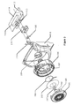
- Figure 3 is an exploded view of a key and knob combination in accordance with another preferred embodiment of the present invention.
- Figure 4 is a sectional view of the key and knob combination shown in figure 3 .
- FIG 2 One preferred embodiment of the present invention is shown in figure 2 , wherein a key and knob combination is arranged on the left side of the radio. Another preferred embodiment is shown in figure 3 and figure 4 .
- the two preferred embodiments show the same internal structure. The only difference between the two preferred embodiments is the protrusions on the surface of the knob 106.
- Figure 2 shows axial stripes
- figure 3 shows up/down arrowheaded protrusions.
- the volume switch 112 is a toggle switch mounted on the volume switching circuit board 114
- the PTT switch 113 is a push switch mounted on the PPT switching circuit board 115.
- other switches of the same kind that are used on existing products may also be used.
- the key and knob combination mainly includes a key 101, a shaft 102, a waterproof ring 103, a metal torsion spring 104, an elastic metal sheet 105, a knob 106, a toggle piece 111, a volume switch 112, a PTT switch 113, a volume switching circuit board 114, a PTT switching circuit board 115, a silica rubber protection pad 116, a clamp 118 and etc.
- the PTT switch is installed inside the silica rubber protection pad 116.
- an axial hole 109 at a position on the housing 110 where the key and knob combination is installed.
- the key 101 has a round surface, and the shaft 102 is located on the inner side of the key 10 and passes through the axial hole, with its front end being capable of moving inward to toggle the PTT switch 113.
- An elastic metal sheet 105 is arranged on the shaft, which shall push the key outwards when it is pressed.
- a waterproof ring 103 that closely matches the inner side of the axle hole is also arranged on the shaft 102, to prevent water from flowing into the housing.
- a ring slot may be provided on the shaft for installing the water proof ring.
- the torsion spring 104 is located between the knob and the housing, facilitating the rotated knob returning to a release position.
- a toggle piece 111 that rotates synchronously with the shaft is placed on the shaft 102 inside the housing.
- the knob 106, the key 101, the shaft 102 and the toggle piece 111 can rotate synchronously through their cooperation, and then the toggle piece is driven to toggle the volume switch 112.
- a radial latch structure is provided between the knob and the key in order to realize a synchronous rotation between the knob, the key, the shaft and the toggle piece, wherein at least a slot 107 is formed on the inner circumference surface of the knob, and a bayonet pin 108 is extended inward from the outer flange of the key. When assembled the bayonet pin is inserted into the corresponding slot to form the said latch structure.
- other structures and configurations may be used for the synchronous rotation between the knob, the key, the shaft and the toggle piece.
- the shaft may be directly driven to rotate synchronously with the knob by an axial protruding part on the shaft latching into an axial slot on the inner side of the axial hole.
- the inner cavity of the knob has a non-circular shape, such as a rectangle shape, and the key also has a corresponding similar shape, then the knob can drive the key to rotate, and in turn cause the shaft and the toggle piece rotating.
- Protrusions are provided on the outer surface of the knob for users to manually rotate the knob. Such protrusions may be stripes parallel with the axis as shown in figure 2 , or arrowheaded protrusions as shown in figure 3 .
- clamp 118 on the shaft at the inner side of the toggle piece 111.
- the clamp (or blocker) is used to prevent the shaft from moving outwards.
- the plunger key is integrated with the rotary knob, to construct a key and knob combination.
- the PTT key when the PTT key is pressed, it may overcome elastic force generated by the elastic sheet 105 to make a displacement, causing the shaft 102 moving axially to finally toggle the PTT switch.
- the elastic sheet 105 recovers and the PTT key also returns to its initial position.
- the knob 102 when the knob 102 is rotated, it drives the shaft 102 and the toggle piece 111 rotating synchronously, and in turn toggling the volume switch 112 to adjust the volume level.
- the torsion spring 104 recovers and pulls the knob returning to the initial position.
- users can press the PTT key to initiate a call or rotate the knob to adjust the volume level through a thumb or a forefinger when operating the radio with a single hand, and the operation is very convenient.
- the shaft 102 acts as a carrier of axial pressure and also rotation, thus only one axial hole is required on the radio housing, to improve the structural reliability of the radio.
Landscapes
- Engineering & Computer Science (AREA)
- Signal Processing (AREA)
- Computer Networks & Wireless Communication (AREA)
- Rotary Switch, Piano Key Switch, And Lever Switch (AREA)
- Switches With Compound Operations (AREA)
- Switch Cases, Indication, And Locking (AREA)
- Telephone Set Structure (AREA)
- Mechanical Control Devices (AREA)
Abstract
Description
- This patent application claims the priority of the Chinese patent application No.
200820092250.2 filed on February 4, 2008 - The present invention relates to portable radios, more particularly, to a radio with a key and knob combination.
- Radios usually have a PTT (Push-to-Talk) key for initiating a call, and a volume control knob for adjusting the volume level. As for the conventional products, a
PTT key 201 and avolume control knob 202 are independent components in the radios, as shown infigure 1 , wherein thePTT key 201 is located at the left side of the radio, and thevolume control knob 202 is located at the top of the radio. - Practically both the PTT key and the volume control knob are frequently used, but they are inconvenient for one-hand operation because they are independent with each other. In addition, two openings on the housing of the radio are required for installing both the PPT key and the volume control knob. This design shall affect structural reliability of the radio.
- The present invention is intended to solve problems caused by the independent PTT key and volume control knob, such as operation inconvenience and less structural reliability.
- According to an aspect of the present invention, a radio with a key and knob combination is provided, comprising a housing, a PTT key unit, a volume control unit and operating circuits arranged in the housing, and the volume control unit includes a knob and a volume switch, the PTT key unit includes a key and a PTT switch; wherein the PTT key unit and the volume control unit are combined together, and the key is installed inside a central cavity of the knob, which is a hollow knob, to form the key and knob combination.
- Advantageously, an axle hole is provided at a position on the housing where the key and knob combination is installed; a shaft on the inner side of the key passes through the axle hole and is capable of moving inward to toggle the PTT switch; and an elastic sheet that pushes the key outwards when being pressed is arranged on the shaft. Preferably, a clamp used to limit displacement of the shaft is located on the shaft near the inner surface of the housing. Preferably, a waterproof ring is placed on the shaft, closely matching the inner side of the axle hole.
- Advantageously, a torsion spring that restores the rotated knob to a release position is located between the knob and the housing; a toggle piece that rotates synchronously with the shaft is placed on the shaft inside the housing; the knob is latched with the key and with the shaft through radial latch structures, enabling the knob, the key, the shaft and the toggle piece rotating synchronously, and then driving the toggle piece to toggle the volume switch.
- Advantageously, at lease a slot is formed on the inner circumference surface of the knob, and a bayonet pin is extended inward from the outer flange of the key, and inserted into the corresponding slot.
- Advantageously, protrusions are formed on the outer surface of the knob for users to manually rotate the knob.
According to the above technical solutions of the present invention, the PTT key unit and the volume control unit are combined together, wherein rotation of the knob may drive the shaft and the toggle piece to rotate synchronously, and then the toggle piece toggles the volume switch, while the pressed key may cause the shaft moving axially to toggle the PTT switch. When operating the radio with a single hand, users can both press the PTT key to initiate a call and rotate the knob to adjust the volume level by a thumb or a forefinger, and the operation is very convenient. Additionally, only an axle hole is required on the radio housing, thus the key and knob combination enhances the structural reliability of the radio. - Embodiments in accordance with the present invention are described below with reference to the following drawings.
-
Figure 1 is a diagram of a traditional two-way radio. -
Figure 2 is a partial perspective view of a key and knob combination in accordance with a preferred embodiment of the present invention. -
Figure 3 is an exploded view of a key and knob combination in accordance with another preferred embodiment of the present invention. -
Figure 4 is a sectional view of the key and knob combination shown infigure 3 . - One preferred embodiment of the present invention is shown in
figure 2 , wherein a key and knob combination is arranged on the left side of the radio. Another preferred embodiment is shown infigure 3 andfigure 4 . The two preferred embodiments show the same internal structure. The only difference between the two preferred embodiments is the protrusions on the surface of theknob 106.Figure 2 shows axial stripes, andfigure 3 shows up/down arrowheaded protrusions. - In the embodiment as shown in
figures 3 and4 , thevolume switch 112 is a toggle switch mounted on the volumeswitching circuit board 114, and thePTT switch 113 is a push switch mounted on the PPTswitching circuit board 115. In various embodiments of the present invention, other switches of the same kind that are used on existing products may also be used. - In the present embodiment, the key and knob combination mainly includes a
key 101, ashaft 102, awaterproof ring 103, ametal torsion spring 104, anelastic metal sheet 105, aknob 106, atoggle piece 111, avolume switch 112, aPTT switch 113, a volumeswitching circuit board 114, a PTTswitching circuit board 115, a silicarubber protection pad 116, aclamp 118 and etc. As shown infigure 4 , the PTT switch is installed inside the silicarubber protection pad 116. - As shown in
figures 3 and4 , there's anaxial hole 109 at a position on thehousing 110 where the key and knob combination is installed. Thekey 101 has a round surface, and theshaft 102 is located on the inner side of the key 10 and passes through the axial hole, with its front end being capable of moving inward to toggle thePTT switch 113. Anelastic metal sheet 105 is arranged on the shaft, which shall push the key outwards when it is pressed. Awaterproof ring 103 that closely matches the inner side of the axle hole is also arranged on theshaft 102, to prevent water from flowing into the housing. In various embodiments, a ring slot may be provided on the shaft for installing the water proof ring. - The
torsion spring 104 is located between the knob and the housing, facilitating the rotated knob returning to a release position. Atoggle piece 111 that rotates synchronously with the shaft is placed on theshaft 102 inside the housing. Theknob 106, thekey 101, theshaft 102 and thetoggle piece 111 can rotate synchronously through their cooperation, and then the toggle piece is driven to toggle thevolume switch 112. - In the present embodiment, a radial latch structure is provided between the knob and the key in order to realize a synchronous rotation between the knob, the key, the shaft and the toggle piece, wherein at least a
slot 107 is formed on the inner circumference surface of the knob, and abayonet pin 108 is extended inward from the outer flange of the key. When assembled the bayonet pin is inserted into the corresponding slot to form the said latch structure. In various embodiments, other structures and configurations may be used for the synchronous rotation between the knob, the key, the shaft and the toggle piece. For example, the shaft may be directly driven to rotate synchronously with the knob by an axial protruding part on the shaft latching into an axial slot on the inner side of the axial hole. Alternatively, the inner cavity of the knob has a non-circular shape, such as a rectangle shape, and the key also has a corresponding similar shape, then the knob can drive the key to rotate, and in turn cause the shaft and the toggle piece rotating. - Protrusions are provided on the outer surface of the knob for users to manually rotate the knob. Such protrusions may be stripes parallel with the axis as shown in
figure 2 , or arrowheaded protrusions as shown infigure 3 . - As shown in
figure 3 , there's aclamp 118 on the shaft at the inner side of thetoggle piece 111. The clamp (or blocker) is used to prevent the shaft from moving outwards. - In the embodiments of the present invention, the plunger key is integrated with the rotary knob, to construct a key and knob combination. As for practical implementation, when the PTT key is pressed, it may overcome elastic force generated by the
elastic sheet 105 to make a displacement, causing theshaft 102 moving axially to finally toggle the PTT switch. When pressure on the PTT key is removed, theelastic sheet 105 recovers and the PTT key also returns to its initial position. On the other hand, when theknob 102 is rotated, it drives theshaft 102 and thetoggle piece 111 rotating synchronously, and in turn toggling thevolume switch 112 to adjust the volume level. When the force acted on the knob is removed, thetorsion spring 104 recovers and pulls the knob returning to the initial position. - In accordance with the embodiments of the present invention, users can press the PTT key to initiate a call or rotate the knob to adjust the volume level through a thumb or a forefinger when operating the radio with a single hand, and the operation is very convenient. Further, the
shaft 102 acts as a carrier of axial pressure and also rotation, thus only one axial hole is required on the radio housing, to improve the structural reliability of the radio.
Claims (10)
- A radio with a key and knob combination comprising a housing , a PTT key unit, a volume control unit, and operating circuits arranged in the housing, the volume control unit includes a knob and a volume switch , the PTT key unit includes a key and a PTT switch ; wherein the PTT key unit and the volume control unit are combined together, the knob is a hollow structure, the key is installed inside a central cavity of the knob, to form the key and knob combination.
- The radio with a key and knob combination according to claim 1, wherein the housing has an axle hole located at a position where the key and knob combination is installed; a shaft on the inner side of the key passes through the axle hole and is capable of moving inward to toggle the PTT switch; and an elastic sheet for pushing the key outwards when being pressed is arranged on the shaft.
- The radio with a key and knob combination according to claim 2, wherein a clamp used to limit displacement of the shaft is set on the shaft near the inner surface of the housing.
- The radio with a key and knob combination according to claim 3, wherein a waterproof ring is placed on the shaft, and contacts with the inner surface of the axle hole in a interference matching.
- The radio with a key and knob combination according to claim 4, wherein a ring slot is formed on the shaft and the water proof ring is placed in the ring slot.
- The radio with a key and knob combination according to claim 2, wherein a torsion spring for returning the rotated knob to a release position is located between the knob and the housing ; a toggle piece that rotates synchronously with the shaft is placed on the shaft inside the housing; the knob is latched with the key through a radial latch structure, which enables the knob, the key, the shaft and the toggle piece rotating synchronously, and then drives the toggle piece to dial the volume switch.
- The radio with a key and knob combination according to claim 6, wherein at lease a slot is formed on an inner circumference surface of the knob, and a bayonet pin is extended inward from an outer flange of the key, and inserted into the corresponding slot to form the latch structure.
- The radio with a key and knob combination according to claim 7, wherein protrusions are formed on the outer surface of the knob for users to manually rotate the knob.
- The radio with a key and knob combination according to claims 2, wherein a torsion spring (104) for returning the rotated knob to a release position is located between the knob and the housing (106); a toggle piece (111) that rotates synchronously with the shaft is placed on the shaft (102) inside the housing; the knob (106) is latched with the shaft (102) through a radial latch structure, which enables the knob, the shaft and the toggle piece rotating synchronously, and then drives the toggle piece to dial the volume switch.
- The radio with a key and knob combination according to claim 9, wherein protrusions are formed on the outer surface of the knob for users to manually rotate the knob.
Applications Claiming Priority (1)
| Application Number | Priority Date | Filing Date | Title |
|---|---|---|---|
| CNU2008200922502U CN201167362Y (en) | 2008-02-04 | 2008-02-04 | Interphone using combined key-press and turn knob |
Publications (3)
| Publication Number | Publication Date |
|---|---|
| EP2086117A2 true EP2086117A2 (en) | 2009-08-05 |
| EP2086117A3 EP2086117A3 (en) | 2012-07-25 |
| EP2086117B1 EP2086117B1 (en) | 2017-08-16 |
Family
ID=40192754
Family Applications (1)
| Application Number | Title | Priority Date | Filing Date |
|---|---|---|---|
| EP08445026.1A Active EP2086117B1 (en) | 2008-02-04 | 2008-08-22 | Radio with a key and knob combination |
Country Status (3)
| Country | Link |
|---|---|
| US (1) | US7962106B2 (en) |
| EP (1) | EP2086117B1 (en) |
| CN (1) | CN201167362Y (en) |
Cited By (1)
| Publication number | Priority date | Publication date | Assignee | Title |
|---|---|---|---|---|
| CN105071822A (en) * | 2012-04-18 | 2015-11-18 | 泉州欧讯电子有限公司 | Vehicle-mounted intercom having a dual-band duplex cross-band transfer function |
Families Citing this family (43)
| Publication number | Priority date | Publication date | Assignee | Title |
|---|---|---|---|---|
| USD605616S1 (en) * | 2009-03-13 | 2009-12-08 | Harris Corporation | Portable communication device |
| USD616844S1 (en) * | 2009-03-16 | 2010-06-01 | Shenzhen Hyt Science & Technology Co. Ltd. | Radio transceiver |
| USD616845S1 (en) * | 2009-03-16 | 2010-06-01 | Shenzhen Hyt Science & Technology Co. Ltd. | Radio transceiver |
| CN102034630B (en) * | 2009-09-29 | 2013-08-28 | 鸿富锦精密工业(深圳)有限公司 | Switch device and host using the same |
| CN101729624B (en) * | 2009-12-26 | 2012-07-25 | 福建南安市泉盛电子有限公司 | Interphone having modified adjusting knob |
| US8532585B2 (en) * | 2010-05-11 | 2013-09-10 | Harris Corporation | Electronic device with rotary knob multi-functional control |
| USD652400S1 (en) * | 2010-08-19 | 2012-01-17 | JVC Kenwood Corporation | Portable radio two-way communications device |
| USD651997S1 (en) * | 2010-08-19 | 2012-01-10 | JVC Kenwood Corporation | Portable radio two-way communications device |
| USD653637S1 (en) * | 2011-03-30 | 2012-02-07 | Motorola Solutions, Inc. | Communication device |
| USD663277S1 (en) * | 2011-05-31 | 2012-07-10 | Motorola Solutions, Inc. | Portable radio housing |
| USD653225S1 (en) * | 2011-05-31 | 2012-01-31 | Motorola Soltutions, Inc. | Portable radio housing |
| USD670258S1 (en) * | 2011-06-13 | 2012-11-06 | JVC Kenwood Corporation | Wireless communication device |
| CN102868390B (en) * | 2011-07-06 | 2016-04-27 | 比亚迪股份有限公司 | A kind of mobile terminal and PTT key asembly thereof |
| USD713809S1 (en) * | 2012-07-06 | 2014-09-23 | JVC Kenwood Corporation | Portable wireless communication device |
| US20140057574A1 (en) * | 2012-08-24 | 2014-02-27 | Motorola Solutions, Inc. | Method and apparatus for controlling receive volume in a two-way radio system |
| CN103178866B (en) * | 2013-02-22 | 2015-08-12 | 海能达通信股份有限公司 | A kind of terminal equipment and using method thereof |
| USD717259S1 (en) * | 2013-02-27 | 2014-11-11 | Motorola Solutions, Inc. | Portable radio communication device |
| USD721050S1 (en) * | 2013-05-22 | 2015-01-13 | Motorola Solutions, Inc. | Housing for a communication device |
| USD749533S1 (en) * | 2013-06-19 | 2016-02-16 | JVC Kenwood Corporation | Portable wireless communication device |
| USD731452S1 (en) * | 2013-06-21 | 2015-06-09 | Motorola Solutions, Inc. | Housing for a portable radio |
| USD761223S1 (en) * | 2014-02-12 | 2016-07-12 | JVC Kenwood Corporation | Communication device |
| USD752537S1 (en) * | 2014-03-12 | 2016-03-29 | JVC Kenwood Corporation | Communication device |
| USD754088S1 (en) * | 2014-05-16 | 2016-04-19 | Motorola Solutions, Inc. | Portable radio |
| USD752536S1 (en) * | 2014-06-16 | 2016-03-29 | Motorola Solutions, Inc. | Portable radio |
| USD761224S1 (en) * | 2014-06-25 | 2016-07-12 | Motorola Solutions, Inc. | Hand-held control head |
| USD754089S1 (en) * | 2014-10-02 | 2016-04-19 | Motorola Solutions, Inc. | Communication device |
| US10248153B2 (en) | 2016-06-07 | 2019-04-02 | Electrolux Home Products, Inc. | Self-centering mechanism for a rotatable shaft |
| JP1590853S (en) * | 2016-11-18 | 2017-11-13 | ||
| CN106714024B (en) * | 2016-12-28 | 2023-09-15 | 歌尔科技有限公司 | Volume adjusting structure |
| JP7008259B2 (en) * | 2017-09-13 | 2022-01-25 | 日本精機株式会社 | Portable communication device |
| JP6985878B2 (en) * | 2017-10-10 | 2021-12-22 | 東洋電装株式会社 | Switch device |
| USD894143S1 (en) * | 2018-01-24 | 2020-08-25 | Icom Incorporated | Portable communication device |
| CN108287656A (en) * | 2018-01-25 | 2018-07-17 | 深圳市宝尔爱迪科技有限公司 | A kind of multi-functional regulating system and method for communication apparatus |
| USD892071S1 (en) * | 2018-06-11 | 2020-08-04 | Shenzhen Jizhida Technology Co., Ltd | Walkie talkie |
| US10356497B1 (en) * | 2018-10-31 | 2019-07-16 | Ian Brown | Removable environmental microphone and radio cover assembly |
| USD881147S1 (en) * | 2018-12-20 | 2020-04-14 | Motorola Solutions, Inc. | Speaker grill for a communication device |
| JP1640694S (en) * | 2019-02-22 | 2019-09-09 | ||
| USD938928S1 (en) * | 2019-03-26 | 2021-12-21 | Black & Decker Inc. | Communication device |
| USD958766S1 (en) * | 2019-06-03 | 2022-07-26 | Motorola Solutions, Inc. | Handheld communication device |
| CN111137465B (en) * | 2019-12-13 | 2021-10-15 | 中国航空工业集团公司西安飞机设计研究所 | Device and method for external call control and adjustment of aircraft audio equipment |
| US11616524B2 (en) * | 2020-06-23 | 2023-03-28 | Joseph K. Greco | Shield for a first responder radio |
| USD1003264S1 (en) * | 2023-04-14 | 2023-10-31 | Yong Wei | Walkie talkie |
| USD1087047S1 (en) * | 2024-01-17 | 2025-08-05 | Jin Li | Walkie talkie |
Citations (1)
| Publication number | Priority date | Publication date | Assignee | Title |
|---|---|---|---|---|
| US20030194975A1 (en) | 1992-09-08 | 2003-10-16 | Takanori Nishiyama | Portable radio telephone set |
Family Cites Families (6)
| Publication number | Priority date | Publication date | Assignee | Title |
|---|---|---|---|---|
| US4147904A (en) * | 1978-03-06 | 1979-04-03 | Telex Communications, Inc. | Microphone with channel selector and push-to-talk button interlock |
| JP3865169B2 (en) * | 1997-11-28 | 2007-01-10 | ソニー株式会社 | COMMUNICATION TERMINAL DEVICE AND COMMUNICATION TERMINAL DEVICE CONTROL METHOD |
| US7038667B1 (en) * | 1998-10-26 | 2006-05-02 | Immersion Corporation | Mechanisms for control knobs and other interface devices |
| US6696915B2 (en) * | 2002-05-14 | 2004-02-24 | Forhouse Corporation | Knob combined a rheostat and a pushbutton |
| US6660947B1 (en) * | 2002-11-26 | 2003-12-09 | General Motors Corporation | Method and apparatus for push-button control |
| KR100662358B1 (en) * | 2004-10-04 | 2007-01-02 | 엘지전자 주식회사 | Mobile communication terminal with audio player operation keys |
-
2008
- 2008-02-04 CN CNU2008200922502U patent/CN201167362Y/en not_active Expired - Lifetime
- 2008-06-06 US US12/134,189 patent/US7962106B2/en active Active
- 2008-08-22 EP EP08445026.1A patent/EP2086117B1/en active Active
Patent Citations (1)
| Publication number | Priority date | Publication date | Assignee | Title |
|---|---|---|---|---|
| US20030194975A1 (en) | 1992-09-08 | 2003-10-16 | Takanori Nishiyama | Portable radio telephone set |
Cited By (1)
| Publication number | Priority date | Publication date | Assignee | Title |
|---|---|---|---|---|
| CN105071822A (en) * | 2012-04-18 | 2015-11-18 | 泉州欧讯电子有限公司 | Vehicle-mounted intercom having a dual-band duplex cross-band transfer function |
Also Published As
| Publication number | Publication date |
|---|---|
| EP2086117A3 (en) | 2012-07-25 |
| US20090197545A1 (en) | 2009-08-06 |
| US7962106B2 (en) | 2011-06-14 |
| CN201167362Y (en) | 2008-12-17 |
| EP2086117B1 (en) | 2017-08-16 |
Similar Documents
| Publication | Publication Date | Title |
|---|---|---|
| EP2086117B1 (en) | Radio with a key and knob combination | |
| EP2099649B1 (en) | Satellite phone holder | |
| JPH09181806A (en) | Radio communication equipment with cover release mechanism arranged in axial direction | |
| CN101469738A (en) | Hinge mechanism and portable electronic device equipped therewith | |
| US5746307A (en) | Switch assembly for a portable radio | |
| DE602006021095D1 (en) | Card issuing mechanism and mobile communication terminal with it | |
| US7237304B2 (en) | Hinge assembly for foldable electronic device | |
| AU2011265655B2 (en) | Assembly for increasing torque tactility of a rotary control for a handheld radio | |
| KR880003046Y1 (en) | Transceiver | |
| CN101657076A (en) | Portable electronic device | |
| CN220041619U (en) | Switch button device suitable for coffee machine | |
| EP1959470A3 (en) | In-vehicle knob switch | |
| CN216928322U (en) | Isolating switch | |
| CN214597179U (en) | Touch panel mounting structure of hand-held game paddle | |
| CN220646371U (en) | Push type sliding locking structure | |
| CN220180401U (en) | Printer capable of integrally controlling printing and opening | |
| KR100652733B1 (en) | Mobile communication terminal with antenna having key function | |
| CN210517202U (en) | Timing socket | |
| CN218889598U (en) | Closestool and quick assembly disassembly device thereof | |
| CN209951148U (en) | Toilet cover plate | |
| CN117612885B (en) | Switch structure and medical power mobile phone | |
| CN223956493U (en) | Wall switch | |
| CN219534366U (en) | Push-turn button control switch | |
| CN114458083B (en) | Handle assembly | |
| CN219610271U (en) | Rotatory button buckle structure and support frame |
Legal Events
| Date | Code | Title | Description |
|---|---|---|---|
| PUAI | Public reference made under article 153(3) epc to a published international application that has entered the european phase |
Free format text: ORIGINAL CODE: 0009012 |
|
| 17P | Request for examination filed |
Effective date: 20080829 |
|
| AK | Designated contracting states |
Kind code of ref document: A2 Designated state(s): AT BE BG CH CY CZ DE DK EE ES FI FR GB GR HR HU IE IS IT LI LT LU LV MC MT NL NO PL PT RO SE SI SK TR |
|
| AX | Request for extension of the european patent |
Extension state: AL BA MK RS |
|
| RAP1 | Party data changed (applicant data changed or rights of an application transferred) |
Owner name: HYTERA COMMUNICATIONS CORP., LTD. |
|
| PUAL | Search report despatched |
Free format text: ORIGINAL CODE: 0009013 |
|
| AK | Designated contracting states |
Kind code of ref document: A3 Designated state(s): AT BE BG CH CY CZ DE DK EE ES FI FR GB GR HR HU IE IS IT LI LT LU LV MC MT NL NO PL PT RO SE SI SK TR |
|
| AX | Request for extension of the european patent |
Extension state: AL BA MK RS |
|
| RIC1 | Information provided on ipc code assigned before grant |
Ipc: H04M 1/23 20060101ALI20120621BHEP Ipc: H04B 1/38 20060101AFI20120621BHEP |
|
| AKX | Designation fees paid |
Designated state(s): AT BE BG CH CY CZ DE DK EE ES FI FR GB GR HR HU IE IS IT LI LT LU LV MC MT NL NO PL PT RO SE SI SK TR |
|
| GRAP | Despatch of communication of intention to grant a patent |
Free format text: ORIGINAL CODE: EPIDOSNIGR1 |
|
| INTG | Intention to grant announced |
Effective date: 20170228 |
|
| GRAS | Grant fee paid |
Free format text: ORIGINAL CODE: EPIDOSNIGR3 |
|
| GRAA | (expected) grant |
Free format text: ORIGINAL CODE: 0009210 |
|
| AK | Designated contracting states |
Kind code of ref document: B1 Designated state(s): AT BE BG CH CY CZ DE DK EE ES FI FR GB GR HR HU IE IS IT LI LT LU LV MC MT NL NO PL PT RO SE SI SK TR |
|
| REG | Reference to a national code |
Ref country code: GB Ref legal event code: FG4D |
|
| REG | Reference to a national code |
Ref country code: CH Ref legal event code: EP |
|
| REG | Reference to a national code |
Ref country code: IE Ref legal event code: FG4D |
|
| REG | Reference to a national code |
Ref country code: AT Ref legal event code: REF Ref document number: 920017 Country of ref document: AT Kind code of ref document: T Effective date: 20170915 |
|
| REG | Reference to a national code |
Ref country code: DE Ref legal event code: R096 Ref document number: 602008051623 Country of ref document: DE |
|
| REG | Reference to a national code |
Ref country code: NL Ref legal event code: MP Effective date: 20170816 |
|
| REG | Reference to a national code |
Ref country code: LT Ref legal event code: MG4D |
|
| REG | Reference to a national code |
Ref country code: AT Ref legal event code: MK05 Ref document number: 920017 Country of ref document: AT Kind code of ref document: T Effective date: 20170816 |
|
| PG25 | Lapsed in a contracting state [announced via postgrant information from national office to epo] |
Ref country code: LT Free format text: LAPSE BECAUSE OF FAILURE TO SUBMIT A TRANSLATION OF THE DESCRIPTION OR TO PAY THE FEE WITHIN THE PRESCRIBED TIME-LIMIT Effective date: 20170816 Ref country code: FI Free format text: LAPSE BECAUSE OF FAILURE TO SUBMIT A TRANSLATION OF THE DESCRIPTION OR TO PAY THE FEE WITHIN THE PRESCRIBED TIME-LIMIT Effective date: 20170816 Ref country code: NO Free format text: LAPSE BECAUSE OF FAILURE TO SUBMIT A TRANSLATION OF THE DESCRIPTION OR TO PAY THE FEE WITHIN THE PRESCRIBED TIME-LIMIT Effective date: 20171116 Ref country code: AT Free format text: LAPSE BECAUSE OF FAILURE TO SUBMIT A TRANSLATION OF THE DESCRIPTION OR TO PAY THE FEE WITHIN THE PRESCRIBED TIME-LIMIT Effective date: 20170816 Ref country code: NL Free format text: LAPSE BECAUSE OF FAILURE TO SUBMIT A TRANSLATION OF THE DESCRIPTION OR TO PAY THE FEE WITHIN THE PRESCRIBED TIME-LIMIT Effective date: 20170816 Ref country code: SE Free format text: LAPSE BECAUSE OF FAILURE TO SUBMIT A TRANSLATION OF THE DESCRIPTION OR TO PAY THE FEE WITHIN THE PRESCRIBED TIME-LIMIT Effective date: 20170816 |
|
| PG25 | Lapsed in a contracting state [announced via postgrant information from national office to epo] |
Ref country code: PL Free format text: LAPSE BECAUSE OF FAILURE TO SUBMIT A TRANSLATION OF THE DESCRIPTION OR TO PAY THE FEE WITHIN THE PRESCRIBED TIME-LIMIT Effective date: 20170816 Ref country code: GR Free format text: LAPSE BECAUSE OF FAILURE TO SUBMIT A TRANSLATION OF THE DESCRIPTION OR TO PAY THE FEE WITHIN THE PRESCRIBED TIME-LIMIT Effective date: 20171117 Ref country code: IS Free format text: LAPSE BECAUSE OF FAILURE TO SUBMIT A TRANSLATION OF THE DESCRIPTION OR TO PAY THE FEE WITHIN THE PRESCRIBED TIME-LIMIT Effective date: 20171216 Ref country code: BG Free format text: LAPSE BECAUSE OF FAILURE TO SUBMIT A TRANSLATION OF THE DESCRIPTION OR TO PAY THE FEE WITHIN THE PRESCRIBED TIME-LIMIT Effective date: 20171116 Ref country code: ES Free format text: LAPSE BECAUSE OF FAILURE TO SUBMIT A TRANSLATION OF THE DESCRIPTION OR TO PAY THE FEE WITHIN THE PRESCRIBED TIME-LIMIT Effective date: 20170816 Ref country code: LV Free format text: LAPSE BECAUSE OF FAILURE TO SUBMIT A TRANSLATION OF THE DESCRIPTION OR TO PAY THE FEE WITHIN THE PRESCRIBED TIME-LIMIT Effective date: 20170816 |
|
| REG | Reference to a national code |
Ref country code: CH Ref legal event code: PL |
|
| PG25 | Lapsed in a contracting state [announced via postgrant information from national office to epo] |
Ref country code: CZ Free format text: LAPSE BECAUSE OF FAILURE TO SUBMIT A TRANSLATION OF THE DESCRIPTION OR TO PAY THE FEE WITHIN THE PRESCRIBED TIME-LIMIT Effective date: 20170816 Ref country code: CH Free format text: LAPSE BECAUSE OF NON-PAYMENT OF DUE FEES Effective date: 20170831 Ref country code: RO Free format text: LAPSE BECAUSE OF FAILURE TO SUBMIT A TRANSLATION OF THE DESCRIPTION OR TO PAY THE FEE WITHIN THE PRESCRIBED TIME-LIMIT Effective date: 20170816 Ref country code: LI Free format text: LAPSE BECAUSE OF NON-PAYMENT OF DUE FEES Effective date: 20170831 Ref country code: DK Free format text: LAPSE BECAUSE OF FAILURE TO SUBMIT A TRANSLATION OF THE DESCRIPTION OR TO PAY THE FEE WITHIN THE PRESCRIBED TIME-LIMIT Effective date: 20170816 |
|
| REG | Reference to a national code |
Ref country code: DE Ref legal event code: R097 Ref document number: 602008051623 Country of ref document: DE |
|
| REG | Reference to a national code |
Ref country code: IE Ref legal event code: MM4A |
|
| PG25 | Lapsed in a contracting state [announced via postgrant information from national office to epo] |
Ref country code: SK Free format text: LAPSE BECAUSE OF FAILURE TO SUBMIT A TRANSLATION OF THE DESCRIPTION OR TO PAY THE FEE WITHIN THE PRESCRIBED TIME-LIMIT Effective date: 20170816 Ref country code: EE Free format text: LAPSE BECAUSE OF FAILURE TO SUBMIT A TRANSLATION OF THE DESCRIPTION OR TO PAY THE FEE WITHIN THE PRESCRIBED TIME-LIMIT Effective date: 20170816 Ref country code: MC Free format text: LAPSE BECAUSE OF FAILURE TO SUBMIT A TRANSLATION OF THE DESCRIPTION OR TO PAY THE FEE WITHIN THE PRESCRIBED TIME-LIMIT Effective date: 20170816 Ref country code: IT Free format text: LAPSE BECAUSE OF FAILURE TO SUBMIT A TRANSLATION OF THE DESCRIPTION OR TO PAY THE FEE WITHIN THE PRESCRIBED TIME-LIMIT Effective date: 20170816 |
|
| REG | Reference to a national code |
Ref country code: BE Ref legal event code: MM Effective date: 20170831 |
|
| PLBE | No opposition filed within time limit |
Free format text: ORIGINAL CODE: 0009261 |
|
| STAA | Information on the status of an ep patent application or granted ep patent |
Free format text: STATUS: NO OPPOSITION FILED WITHIN TIME LIMIT |
|
| PG25 | Lapsed in a contracting state [announced via postgrant information from national office to epo] |
Ref country code: LU Free format text: LAPSE BECAUSE OF NON-PAYMENT OF DUE FEES Effective date: 20170822 |
|
| REG | Reference to a national code |
Ref country code: FR Ref legal event code: ST Effective date: 20180606 |
|
| 26N | No opposition filed |
Effective date: 20180517 |
|
| GBPC | Gb: european patent ceased through non-payment of renewal fee |
Effective date: 20171116 |
|
| PG25 | Lapsed in a contracting state [announced via postgrant information from national office to epo] |
Ref country code: IE Free format text: LAPSE BECAUSE OF NON-PAYMENT OF DUE FEES Effective date: 20170822 |
|
| PG25 | Lapsed in a contracting state [announced via postgrant information from national office to epo] |
Ref country code: BE Free format text: LAPSE BECAUSE OF NON-PAYMENT OF DUE FEES Effective date: 20170831 Ref country code: FR Free format text: LAPSE BECAUSE OF NON-PAYMENT OF DUE FEES Effective date: 20171016 Ref country code: SI Free format text: LAPSE BECAUSE OF FAILURE TO SUBMIT A TRANSLATION OF THE DESCRIPTION OR TO PAY THE FEE WITHIN THE PRESCRIBED TIME-LIMIT Effective date: 20170816 |
|
| PG25 | Lapsed in a contracting state [announced via postgrant information from national office to epo] |
Ref country code: MT Free format text: LAPSE BECAUSE OF NON-PAYMENT OF DUE FEES Effective date: 20170822 |
|
| PG25 | Lapsed in a contracting state [announced via postgrant information from national office to epo] |
Ref country code: GB Free format text: LAPSE BECAUSE OF NON-PAYMENT OF DUE FEES Effective date: 20171116 |
|
| PG25 | Lapsed in a contracting state [announced via postgrant information from national office to epo] |
Ref country code: HU Free format text: LAPSE BECAUSE OF FAILURE TO SUBMIT A TRANSLATION OF THE DESCRIPTION OR TO PAY THE FEE WITHIN THE PRESCRIBED TIME-LIMIT; INVALID AB INITIO Effective date: 20080822 |
|
| PG25 | Lapsed in a contracting state [announced via postgrant information from national office to epo] |
Ref country code: CY Free format text: LAPSE BECAUSE OF NON-PAYMENT OF DUE FEES Effective date: 20170816 |
|
| PG25 | Lapsed in a contracting state [announced via postgrant information from national office to epo] |
Ref country code: TR Free format text: LAPSE BECAUSE OF FAILURE TO SUBMIT A TRANSLATION OF THE DESCRIPTION OR TO PAY THE FEE WITHIN THE PRESCRIBED TIME-LIMIT Effective date: 20170816 |
|
| PG25 | Lapsed in a contracting state [announced via postgrant information from national office to epo] |
Ref country code: PT Free format text: LAPSE BECAUSE OF FAILURE TO SUBMIT A TRANSLATION OF THE DESCRIPTION OR TO PAY THE FEE WITHIN THE PRESCRIBED TIME-LIMIT Effective date: 20170816 |
|
| PG25 | Lapsed in a contracting state [announced via postgrant information from national office to epo] |
Ref country code: HR Free format text: LAPSE BECAUSE OF FAILURE TO SUBMIT A TRANSLATION OF THE DESCRIPTION OR TO PAY THE FEE WITHIN THE PRESCRIBED TIME-LIMIT Effective date: 20170816 |
|
| PGFP | Annual fee paid to national office [announced via postgrant information from national office to epo] |
Ref country code: DE Payment date: 20250812 Year of fee payment: 18 |