EP2086041B1 - Apparatus for making tubular-shaped membrane electrode assemblies - Google Patents
Apparatus for making tubular-shaped membrane electrode assemblies Download PDFInfo
- Publication number
- EP2086041B1 EP2086041B1 EP08101243A EP08101243A EP2086041B1 EP 2086041 B1 EP2086041 B1 EP 2086041B1 EP 08101243 A EP08101243 A EP 08101243A EP 08101243 A EP08101243 A EP 08101243A EP 2086041 B1 EP2086041 B1 EP 2086041B1
- Authority
- EP
- European Patent Office
- Prior art keywords
- catalyst
- tubular
- proton
- membrane
- unit
- Prior art date
- Legal status (The legal status is an assumption and is not a legal conclusion. Google has not performed a legal analysis and makes no representation as to the accuracy of the status listed.)
- Not-in-force
Links
- 239000012528 membrane Substances 0.000 title claims abstract description 48
- 230000000712 assembly Effects 0.000 title description 4
- 238000000429 assembly Methods 0.000 title description 4
- 239000003054 catalyst Substances 0.000 claims abstract description 43
- 239000004744 fabric Substances 0.000 claims abstract description 31
- 238000009941 weaving Methods 0.000 claims abstract description 23
- 239000000835 fiber Substances 0.000 claims abstract description 13
- 238000001816 cooling Methods 0.000 claims abstract description 9
- 238000004519 manufacturing process Methods 0.000 claims abstract description 7
- 239000011347 resin Substances 0.000 claims description 12
- 229920005989 resin Polymers 0.000 claims description 12
- 239000000446 fuel Substances 0.000 claims description 8
- 239000002243 precursor Substances 0.000 claims description 5
- 239000007788 liquid Substances 0.000 claims description 4
- 239000002002 slurry Substances 0.000 claims description 4
- OKTJSMMVPCPJKN-UHFFFAOYSA-N Carbon Chemical compound [C] OKTJSMMVPCPJKN-UHFFFAOYSA-N 0.000 claims description 3
- 229910052799 carbon Inorganic materials 0.000 claims description 3
- 239000000843 powder Substances 0.000 claims description 2
- 239000006072 paste Substances 0.000 claims 2
- 239000000155 melt Substances 0.000 claims 1
- 238000000034 method Methods 0.000 description 3
- 238000005520 cutting process Methods 0.000 description 1
- 238000010586 diagram Methods 0.000 description 1
- 238000001125 extrusion Methods 0.000 description 1
- 238000010438 heat treatment Methods 0.000 description 1
- 238000002347 injection Methods 0.000 description 1
- 239000007924 injection Substances 0.000 description 1
- 238000005342 ion exchange Methods 0.000 description 1
- 239000000463 material Substances 0.000 description 1
- 238000002844 melting Methods 0.000 description 1
- 230000008018 melting Effects 0.000 description 1
- 238000002156 mixing Methods 0.000 description 1
- 229920000642 polymer Polymers 0.000 description 1
- 239000005518 polymer electrolyte Substances 0.000 description 1
- 238000003825 pressing Methods 0.000 description 1
Images



Classifications
-
- H—ELECTRICITY
- H01—ELECTRIC ELEMENTS
- H01M—PROCESSES OR MEANS, e.g. BATTERIES, FOR THE DIRECT CONVERSION OF CHEMICAL ENERGY INTO ELECTRICAL ENERGY
- H01M8/00—Fuel cells; Manufacture thereof
-
- H—ELECTRICITY
- H01—ELECTRIC ELEMENTS
- H01M—PROCESSES OR MEANS, e.g. BATTERIES, FOR THE DIRECT CONVERSION OF CHEMICAL ENERGY INTO ELECTRICAL ENERGY
- H01M4/00—Electrodes
- H01M4/86—Inert electrodes with catalytic activity, e.g. for fuel cells
- H01M4/88—Processes of manufacture
- H01M4/8803—Supports for the deposition of the catalytic active composition
- H01M4/881—Electrolytic membranes
-
- H—ELECTRICITY
- H01—ELECTRIC ELEMENTS
- H01M—PROCESSES OR MEANS, e.g. BATTERIES, FOR THE DIRECT CONVERSION OF CHEMICAL ENERGY INTO ELECTRICAL ENERGY
- H01M4/00—Electrodes
- H01M4/86—Inert electrodes with catalytic activity, e.g. for fuel cells
- H01M4/88—Processes of manufacture
- H01M4/8825—Methods for deposition of the catalytic active composition
- H01M4/8828—Coating with slurry or ink
-
- H—ELECTRICITY
- H01—ELECTRIC ELEMENTS
- H01M—PROCESSES OR MEANS, e.g. BATTERIES, FOR THE DIRECT CONVERSION OF CHEMICAL ENERGY INTO ELECTRICAL ENERGY
- H01M8/00—Fuel cells; Manufacture thereof
- H01M8/002—Shape, form of a fuel cell
- H01M8/004—Cylindrical, tubular or wound
-
- H—ELECTRICITY
- H01—ELECTRIC ELEMENTS
- H01M—PROCESSES OR MEANS, e.g. BATTERIES, FOR THE DIRECT CONVERSION OF CHEMICAL ENERGY INTO ELECTRICAL ENERGY
- H01M8/00—Fuel cells; Manufacture thereof
- H01M8/10—Fuel cells with solid electrolytes
- H01M8/1016—Fuel cells with solid electrolytes characterised by the electrolyte material
- H01M8/1018—Polymeric electrolyte materials
- H01M8/1069—Polymeric electrolyte materials characterised by the manufacturing processes
- H01M8/1083—Starting from polymer melts other than monomer melts
-
- H—ELECTRICITY
- H01—ELECTRIC ELEMENTS
- H01M—PROCESSES OR MEANS, e.g. BATTERIES, FOR THE DIRECT CONVERSION OF CHEMICAL ENERGY INTO ELECTRICAL ENERGY
- H01M8/00—Fuel cells; Manufacture thereof
- H01M8/10—Fuel cells with solid electrolytes
- H01M8/1016—Fuel cells with solid electrolytes characterised by the electrolyte material
- H01M8/1018—Polymeric electrolyte materials
- H01M8/1069—Polymeric electrolyte materials characterised by the manufacturing processes
- H01M8/1086—After-treatment of the membrane other than by polymerisation
- H01M8/1088—Chemical modification, e.g. sulfonation
-
- Y—GENERAL TAGGING OF NEW TECHNOLOGICAL DEVELOPMENTS; GENERAL TAGGING OF CROSS-SECTIONAL TECHNOLOGIES SPANNING OVER SEVERAL SECTIONS OF THE IPC; TECHNICAL SUBJECTS COVERED BY FORMER USPC CROSS-REFERENCE ART COLLECTIONS [XRACs] AND DIGESTS
- Y02—TECHNOLOGIES OR APPLICATIONS FOR MITIGATION OR ADAPTATION AGAINST CLIMATE CHANGE
- Y02E—REDUCTION OF GREENHOUSE GAS [GHG] EMISSIONS, RELATED TO ENERGY GENERATION, TRANSMISSION OR DISTRIBUTION
- Y02E60/00—Enabling technologies; Technologies with a potential or indirect contribution to GHG emissions mitigation
- Y02E60/30—Hydrogen technology
- Y02E60/50—Fuel cells
-
- Y—GENERAL TAGGING OF NEW TECHNOLOGICAL DEVELOPMENTS; GENERAL TAGGING OF CROSS-SECTIONAL TECHNOLOGIES SPANNING OVER SEVERAL SECTIONS OF THE IPC; TECHNICAL SUBJECTS COVERED BY FORMER USPC CROSS-REFERENCE ART COLLECTIONS [XRACs] AND DIGESTS
- Y02—TECHNOLOGIES OR APPLICATIONS FOR MITIGATION OR ADAPTATION AGAINST CLIMATE CHANGE
- Y02P—CLIMATE CHANGE MITIGATION TECHNOLOGIES IN THE PRODUCTION OR PROCESSING OF GOODS
- Y02P70/00—Climate change mitigation technologies in the production process for final industrial or consumer products
- Y02P70/50—Manufacturing or production processes characterised by the final manufactured product
Definitions
- the present invention relates to an apparatus for making a tubular-shaped membrane electrode assembly (MEA) and, more particularly, to an apparatus for the mass production of tubular-shaped membrane electrode assemblies.
- MEA tubular-shaped membrane electrode assembly
- a tubular-shaped membrane electrode assembly includes a tubular-shaped proton-exchange membrane, a pair of catalyst layers and a pair of electron conductive clothes with leading wire.
- a precursor of tubular-shaped proton exchange membrane precursor is made of polymer in a melting and injection process.
- the tubular-shaped precursor is converted into the tubular-shaped proton-exchange membrane in an ion exchange process.
- Electrode catalyst paste is made via mixing electrode catalyst with material for making the proton exchange membrane.
- the electrode catalyst paste is coated on the tubular-shaped conductive cloth.
- the tubular-shaped proton-exchange membrane is inserted in between the pair of tubular-shaped conductive cloth with catalyst paste coated.
- This aligned entity of the tubular-shaped proton-exchange membrane, and the two tubular-shaped conductive cloth with catalyst paste coated are set in a mold, subjected to a heating and pressing process and removed from the mold.
- the tubular-shaped membrane electrode assembly is made.
- the present invention is intended to alleviate or abbreviate the above-mentioned problems and make the tubular-shaped membrane electrode assembly be mass-produced continuously.
- a method of making a tubular-shaped membrane electrode assembly of the type using woven electrodes is known from WO 03/103079 A2 .
- a method of continuously making a tubular shaped membrane electrode assembly by extrusion of the electrodes and the polymer electrolyte is known from WO 2007/029873 A1 .
- the object of the present invention is to provide a technical apparatus for the making of a tubular-shaped membrane electrode assembly of the type using woven electrodes.
- an apparatus is devised to make tubular-shaped membrane electrode assembly according to the preferred embodiment of the present invention.
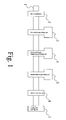
- the apparatus includes a guiding unit I (such as guiding rod, guiding tube or guiding wire) to guide the direction of MEA production, a first weaving unit 2 for weaving conductive fiber bundles into a first tubular conductive fabric around the guiding unit (or guiding rod, or guiding tube or guiding wire), a first catalyst-providing unit 3 for forming a first catalyst film on the first tubular conductive fabric, a proton-exchange-membrane-providing unit 4 for providing a proton-exchange-membrane on the first catalyst film, a second catalyst-providing unit 5 for forming a second catalyst film on the proton-exchange membrane, a second weaving unit 6 for weaving conductive fiber bundles into a second tubular conductive fabric on the second catalyst film, and a cooling and pulling unit 7 for cooling and pulling the first tubular conductive fabric, the first catalyst film, the proto
- the guiding unit 1 is inserted through the first weaving unit 2, the first catalyst-providing unit 3, the proton-exchange-membrane-providing unit 4, the second catalyst-providing unit 5, the second weaving unit 6 and (or not necessary through) the cooling and pulling unit 7 arranged in order.
- conductive fiber bundles 20 are provided in the first weaving unit 2.
- the conductive fiber bundles 20 may be made of carbon.
- the conductive fiber bundles 20 are woven into a first tubular conductive fabric 21 around the guiding rod 1. Then, the first tubular conductive fabric 21 is moved into the first catalyst-providing unit 30 along the guiding rod 1.
- electrode catalyst 30 suitable for fuel cells is provided, in liquid (or slurry, or paste), onto the tubular conductive fabric 21. After setting, the electrode catalyst 30 becomes a first catalyst film 31 around the tubular conductive fabric 21. Then, they are moved into the proton-exchange membrane -providing unit 4 along the guiding unit 1.
- resin grains or powders 40 are molten and provided onto the first catalyst film 31.
- the resin may be proton-exchanging resin or precursor. After setting, the resin forms a proton-exchange membrane 41 around the first catalyst film 31. Then, they are moved into the second catalyst-providing unit 5.
- electrode catalyst 50 suitable for fuel cells is provided, in liquid (or slurry, or paste), onto the proton-exchange-membrane 41. After setting, the electrode catalyst 50 becomes a second catalyst film 51 around the proton-exchange membrane 41. Then, they are moved into the second weaving unit 6 along the guiding rod 1.
- conductive fiber bundles 60 are provided.
- the conductive fiber bundles 60 may be made of carbon.
- the conductive fiber bundles 60 are woven into a second tubular conductive fabric 61 around the second catalyst film 51. Then, they are moved into the cooling and pulling unit 7 along the guiding rod 1 or the extending direction of the guiding rod 1.
- the first conductive fabric 21, the first catalyst film 31, the proton-exchange-membrane 41, the second catalyst film 51 and the second tubular conductive fabric 61 are cooled and pulled, thus forming a tubular laminate 8.
- the thickness of proton-exchange membrane is in the range of one tenth to ten times of the inside diameter of the tubular-shaped membrane electrode assembly 8.
- the thickness of the first and second catalyst films 31 and 51 is one tenth of a micrometer to several millimeters.
- the tubular laminate 8 may be sent to a cutting unit 90 where the tubular laminate 8 is cut into tubular-shaped membrane electrode assemblies of appropriate lengths.
- tubular laminate 8 may be sent to a reeling unit 91 where the tubular laminate 8 is reeled.
- the tubular laminate 8 can later be cut into tubular-shaped membrane electrode assemblies of appropriate lengths.
- the apparatus shown in Fig. 2 can be used to make leads shown in Fig. 4 .
- the first and second catalyst-providing units 3 and 5 are stopped. That is, only the first weaving unit 2, the proton-exchange-membrane-providing unit 4 and the second weaving unit 6 are activated to make a tubular assembly 8a including only the first and second tubular conductive fabrics 21 and 61 and the proton-exchange membrane 41. Later, the tubular assembly 8a can be cut and becomes a leading part of tubular-shaped MEA with leading part. This leading part may be used for binding in fuel cell assembly later.
- the apparatus shown in Fig. 2 can be used to make leads shown in Fig. 5 .
- the first and second catalyst-providing units 3 and 5 and the proton-exchange-membrane -providing unit 4 are stopped. That is, only the first and second weaving units 2 and 6 are activated to make a pair of the leading wire 8b including only the first and second tubular conductive fabrics 21 and 61. Later, the pair of leading wire 8b can be cut and become the leading wires of current collectors of both electrodes of the tubular-shaped MEA for fuel cell assembly.
Landscapes
- Engineering & Computer Science (AREA)
- Manufacturing & Machinery (AREA)
- Chemical & Material Sciences (AREA)
- General Chemical & Material Sciences (AREA)
- Chemical Kinetics & Catalysis (AREA)
- Electrochemistry (AREA)
- Life Sciences & Earth Sciences (AREA)
- Sustainable Development (AREA)
- Sustainable Energy (AREA)
- Fuel Cell (AREA)
- Catalysts (AREA)
- Inert Electrodes (AREA)
Abstract
Description
- The present invention relates to an apparatus for making a tubular-shaped membrane electrode assembly (MEA) and, more particularly, to an apparatus for the mass production of tubular-shaped membrane electrode assemblies.
- As disclosed in Taiwanese Patent
M274656 US2006/0251942 A1 ), a tubular-shaped membrane electrode assembly includes a tubular-shaped proton-exchange membrane, a pair of catalyst layers and a pair of electron conductive clothes with leading wire. To make the tubular-shaped membrane electrode assembly, a precursor of tubular-shaped proton exchange membrane precursor is made of polymer in a melting and injection process. The tubular-shaped precursor is converted into the tubular-shaped proton-exchange membrane in an ion exchange process. Electrode catalyst paste is made via mixing electrode catalyst with material for making the proton exchange membrane. The electrode catalyst paste is coated on the tubular-shaped conductive cloth. The tubular-shaped proton-exchange membrane is inserted in between the pair of tubular-shaped conductive cloth with catalyst paste coated. This aligned entity of the tubular-shaped proton-exchange membrane, and the two tubular-shaped conductive cloth with catalyst paste coated are set in a mold, subjected to a heating and pressing process and removed from the mold. Thus, the tubular-shaped membrane electrode assembly is made. - With the manufacturing method mentioned above, only batch type manufacturing process is available. It means loss of efficiency and cost of much.The present invention is intended to alleviate or abbreviate the above-mentioned problems and make the tubular-shaped membrane electrode assembly be mass-produced continuously.
- A method of making a tubular-shaped membrane electrode assembly of the type using woven electrodes is is known from
WO 03/103079 A2 WO 2007/029873 A1 . - The object of the present invention is to provide a technical apparatus for the making of a tubular-shaped membrane electrode assembly of the type using woven electrodes.
- This object is achieved by an apparatus comprising the features of claim 1. Advanantageous embodiments are indicated in further claims.
- Other objectives, advantages and features of the present invention will become apparent from the following description referring to the attached drawings.
- The present invention will be described via the detailed illustration of the preferred embodiment referring to the drawings.
-
Fig. 1 is a block diagram of an apparatus for making tubular-shaped membrane electrode assembly according to the preferred embodiment of the present invention. -
Fig. 2 is a more detailed typical drawing for the apparatus shown inFig. 1 . -
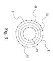
Fig. 3 is a cross-sectional view of a tubular-shaped membrane electrode assembly made by the apparatus shown inFig. 2 . -
Fig. 4 is a cross-sectional view of a tubular assembly without catalyst layers made by the apparatus shown inFig. 2 . -
Fig. 5 is a cross-sectional view of a pair of leading wires made by the apparatus shown inFig. 2 . - According to
Fig. 1 , an apparatus is devised to make tubular-shaped membrane electrode assembly according to the preferred embodiment of the present invention. The apparatus includes a guiding unit I (such as guiding rod, guiding tube or guiding wire) to guide the direction of MEA production, afirst weaving unit 2 for weaving conductive fiber bundles into a first tubular conductive fabric around the guiding unit (or guiding rod, or guiding tube or guiding wire), a first catalyst-providing unit 3 for forming a first catalyst film on the first tubular conductive fabric, a proton-exchange-membrane-providingunit 4 for providing a proton-exchange-membrane on the first catalyst film, a second catalyst-providingunit 5 for forming a second catalyst film on the proton-exchange membrane, asecond weaving unit 6 for weaving conductive fiber bundles into a second tubular conductive fabric on the second catalyst film, and a cooling andpulling unit 7 for cooling and pulling the first tubular conductive fabric, the first catalyst film, the proton-exchange-membrane, the second catalyst film and the second tubular conductive fabric into a tubular laminate that can be cut into tubular-shaped membrane electrode assembly of appropriate lengths. The guiding unit 1 is inserted through thefirst weaving unit 2, the first catalyst-providing unit 3, the proton-exchange-membrane-providingunit 4, the second catalyst-providingunit 5, thesecond weaving unit 6 and (or not necessary through) the cooling andpulling unit 7 arranged in order. - Referring to
Figs. 2 and3 , in thefirst weaving unit 2,conductive fiber bundles 20 are provided. Theconductive fiber bundles 20 may be made of carbon. Theconductive fiber bundles 20 are woven into a first tubularconductive fabric 21 around the guiding rod 1. Then, the first tubularconductive fabric 21 is moved into the first catalyst-providingunit 30 along the guiding rod 1. - In the first catalyst-providing unit 3,
electrode catalyst 30 suitable for fuel cells is provided, in liquid (or slurry, or paste), onto the tubularconductive fabric 21. After setting, theelectrode catalyst 30 becomes afirst catalyst film 31 around the tubularconductive fabric 21. Then, they are moved into the proton-exchange membrane -providingunit 4 along the guiding unit 1. - In the proton-exchange membrane-providing
unit 4, resin grains orpowders 40 are molten and provided onto thefirst catalyst film 31. The resin may be proton-exchanging resin or precursor. After setting, the resin forms a proton-exchange membrane 41 around thefirst catalyst film 31. Then, they are moved into the second catalyst-providingunit 5. - In the second catalyst-providing
unit 5,electrode catalyst 50 suitable for fuel cells is provided, in liquid (or slurry, or paste), onto the proton-exchange-membrane 41. After setting, theelectrode catalyst 50 becomes asecond catalyst film 51 around the proton-exchange membrane 41. Then, they are moved into thesecond weaving unit 6 along the guiding rod 1. - In the
second weaving unit 6,conductive fiber bundles 60 are provided. Theconductive fiber bundles 60 may be made of carbon. Theconductive fiber bundles 60 are woven into a second tubularconductive fabric 61 around thesecond catalyst film 51. Then, they are moved into the cooling and pullingunit 7 along the guiding rod 1 or the extending direction of the guiding rod 1. - In the cooling and
pulling unit 7, the firstconductive fabric 21, thefirst catalyst film 31, the proton-exchange-membrane 41, thesecond catalyst film 51 and the second tubularconductive fabric 61 are cooled and pulled, thus forming atubular laminate 8. The thickness of proton-exchange membrane is in the range of one tenth to ten times of the inside diameter of the tubular-shapedmembrane electrode assembly 8. The thickness of the first andsecond catalyst films - The
tubular laminate 8 may be sent to acutting unit 90 where thetubular laminate 8 is cut into tubular-shaped membrane electrode assemblies of appropriate lengths. - Alternatively, the
tubular laminate 8 may be sent to areeling unit 91 where thetubular laminate 8 is reeled. Thetubular laminate 8 can later be cut into tubular-shaped membrane electrode assemblies of appropriate lengths. - The apparatus shown in
Fig. 2 can be used to make leads shown inFig. 4 . In this case, the first and second catalyst-providingunits 3 and 5 are stopped. That is, only thefirst weaving unit 2, the proton-exchange-membrane-providingunit 4 and thesecond weaving unit 6 are activated to make atubular assembly 8a including only the first and second tubularconductive fabrics exchange membrane 41. Later, thetubular assembly 8a can be cut and becomes a leading part of tubular-shaped MEA with leading part. This leading part may be used for binding in fuel cell assembly later. - The apparatus shown in
Fig. 2 can be used to make leads shown inFig. 5 . In this case, the first and second catalyst-providingunits 3 and 5 and the proton-exchange-membrane -providingunit 4 are stopped. That is, only the first andsecond weaving units conductive fabrics - The present invention has been described via the detailed illustration of the preferred embodiment. Those skilled in the art can derive variations from the preferred embodiment without departing from the scope of the present invention. Therefore, the preferred embodiment shall not limit the scope of the present invention defined in the claims.
Claims (12)
- An apparatus for continuously making a tubular-shaped membrane electrode assembly comprising:a guiding unit (1) for guiding the direction of MEA production;a first weaving unit (2) for weaving conductive fiber bundles into a first tubular conductive fabric around the guiding unit;a first catalyst-providing unit (3) for forming a first catalyst film on the first tubular conductive fabric;a proton-exchange-membrane-providing unit (4) for providing a proton-exchange-membrane on the first catalyst film;a second catalyst-providing unit (5) for forming a second catalyst film on the proton-exchange-membrane;a second weaving unit (6) for weaving conductive fiber bundles into a second tubular conductive fabric on the second catalyst film;a cooling and pulling unit (7) for cooling and pulling the first tubular conductive fabric, the first catalyst film, the proton-exchange-membrane, the second catalyst film and the second tubular conductive fabric into a tubular laminate that can be cut into tubular-shaped membrane electrode assembly of appropriate lengths,characterized in thatthe proton-exchange-membrane-providing unit (4) melts resin grains or powders and provides the molten resin onto the first catalyst layer.
- The apparatus according to claim 1, wherein the conductive fiber bundles are made of carbon.
- The apparatus according to claim 1 or 2, wherein the first catalyst-providing unit provides electrode catalyst suitable for fuel cells on the first tubular conductive fabric.
- The apparatus according to claim 1 or 2, wherein the first catalyst-providing unit provides electrode catalyst suitable for fuel cells in liquid, slurry or paste on the first tubular conductive fabric.
- The apparatus according to one of claims 1 to 4, wherein the resin is proton-exchanging resin.
- The apparatus according to one of claims 1 to 4, wherein the resin is precursor of proton-exchanging resin.
- The apparatus according to one of claims 1 to 6, wherein the second catalyst-providing unit provides electrode catalyst suitable for fuel cells on the proton-exchanging resin.
- The apparatus according to one of claims 1 to 6, wherein the second catalyst-providing unit provides electrode catalyst suitable for fuel cells in liquid, slurry or paste on the proton-exchanging resin.
- The apparatus according to one of claims 1 to 8, wherein the thickness of proton-exchange membrane is in the range of one tenth to ten times of the inside diameter of the tubular-shaped membrane electrode assembly.
- The apparatus according to one of claims 1 to 9, wherein the thickness of the first and second catalyst films is one tenth of a micrometer to several millimeters.
- The apparatus according to one of claims 1 to 8, wherein said apparatus has a first working mode in which the first and second catalyst-providing units (3, 5) are stopped while only the first weaving unit (2), the proton-exchange-membrane-providing unit (4) and the second weaving unit (6) are activated to make a tubular assembly including only the first and second tubular conductive fabrics and and the proton-exchange membrane 41.
- The apparatus according to one of claims 1 to 9, wherein said apparatus has a second working mode in which the first and second catalyst-providing units (3, 5) and the proton-exchange-membrane - providing unit (4) are stopped while only the first and second weaving units (2 and 6) are activated to make a pair of leading wires including only the first and second tubular conductive fabrics.
Priority Applications (2)
| Application Number | Priority Date | Filing Date | Title |
|---|---|---|---|
| EP08101243A EP2086041B1 (en) | 2008-02-04 | 2008-02-04 | Apparatus for making tubular-shaped membrane electrode assemblies |
| AT08101243T ATE523907T1 (en) | 2008-02-04 | 2008-02-04 | DEVICE FOR PRODUCING TUBULAR MEMBRANE ELECTRODE UNITS |
Applications Claiming Priority (1)
| Application Number | Priority Date | Filing Date | Title |
|---|---|---|---|
| EP08101243A EP2086041B1 (en) | 2008-02-04 | 2008-02-04 | Apparatus for making tubular-shaped membrane electrode assemblies |
Publications (2)
| Publication Number | Publication Date |
|---|---|
| EP2086041A1 EP2086041A1 (en) | 2009-08-05 |
| EP2086041B1 true EP2086041B1 (en) | 2011-09-07 |
Family
ID=39561874
Family Applications (1)
| Application Number | Title | Priority Date | Filing Date |
|---|---|---|---|
| EP08101243A Not-in-force EP2086041B1 (en) | 2008-02-04 | 2008-02-04 | Apparatus for making tubular-shaped membrane electrode assemblies |
Country Status (2)
| Country | Link |
|---|---|
| EP (1) | EP2086041B1 (en) |
| AT (1) | ATE523907T1 (en) |
Families Citing this family (1)
| Publication number | Priority date | Publication date | Assignee | Title |
|---|---|---|---|---|
| GB0916179D0 (en) | 2009-09-16 | 2009-10-28 | Smith Rachel L | Coaxial device |
Family Cites Families (4)
| Publication number | Priority date | Publication date | Assignee | Title |
|---|---|---|---|---|
| DE10224783A1 (en) | 2002-06-04 | 2004-01-08 | Höhberger, Ulrich Felix Hermann, Dipl.-Ing. | Waveguide fuel cell element with conductor arrangement and method for manufacturing |
| US7378172B2 (en) | 2005-05-09 | 2008-05-27 | Atomic Energy Council - Institute Of Nuclear Energy Research | Tubular membrane electrode assembly with leading wire |
| JP5061440B2 (en) * | 2005-09-08 | 2012-10-31 | トヨタ自動車株式会社 | Fuel cell manufacturing method and fuel cell manufacturing apparatus |
| WO2007147271A1 (en) * | 2006-06-19 | 2007-12-27 | Huber+Suhner Ag | High-frequency component and method for the production of same |
-
2008
- 2008-02-04 EP EP08101243A patent/EP2086041B1/en not_active Not-in-force
- 2008-02-04 AT AT08101243T patent/ATE523907T1/en not_active IP Right Cessation
Also Published As
| Publication number | Publication date |
|---|---|
| ATE523907T1 (en) | 2011-09-15 |
| EP2086041A1 (en) | 2009-08-05 |
Similar Documents
| Publication | Publication Date | Title |
|---|---|---|
| US8790846B2 (en) | Gas diffusion layer and process for production thereof, and fuel cell | |
| US8597453B2 (en) | Method for producing highly conductive sheet molding compound, fuel cell flow field plate, and bipolar plate | |
| US8518603B2 (en) | Sheet molding compound flow field plate, bipolar plate and fuel cell | |
| CN102301509B (en) | Porous electrode base material, its manufacture method, film-electrode bond and polymer electrolyte fuel cell | |
| CN106876740A (en) | A kind of fuel cell continuous producing method of soft graphite bi-polar plate | |
| KR101371337B1 (en) | Carbon fabric bipolar plate of fuel cell and method for manufacturing the same | |
| CN115347325B (en) | Composite diaphragm, preparation method thereof and sodium ion battery | |
| JP2002500422A (en) | Continuous manufacturing method of laminated electrolyte and electrode assembly | |
| CN106876723B (en) | A method for continuous production of flexible graphite plate single cells for fuel cells | |
| CN108321400A (en) | Fuel cell is molded the pairs of production method of bipolar plates | |
| JP6011859B2 (en) | Method for producing porous electrode substrate precursor sheet and porous electrode substrate precursor sheet | |
| KR101315738B1 (en) | Manufacturing method of prepreg for composite separation plate, and manufacturing method of composite separation plate for fuel cell using the same | |
| EP2086041B1 (en) | Apparatus for making tubular-shaped membrane electrode assemblies | |
| CN117790876B (en) | Battery cell winding equipment and method | |
| US7877851B2 (en) | Apparatus for making tubular film transistors | |
| US20170298200A1 (en) | Thermoplastic prepreg intermediate material for fuel cell separation plate and method for manufacturing thermoplastic prepreg for fuel cell separation plate by using same | |
| CN214957021U (en) | Thermal compound roller set and thermal compound equipment | |
| CN107316966A (en) | It is a kind of to soak mould for nano electrostatic spinning barrier film of ferric phosphate lithium cell and preparation method thereof and pressure | |
| KR101306686B1 (en) | Separation plate for fuel cell and method for manufacturing the same | |
| JP2014175286A (en) | Fuel battery and manufacturing method thereof | |
| CN116387600A (en) | High-speed winding systems and methods for solid-state batteries | |
| CN117810354A (en) | Dry membrane preparation method and device | |
| KR102060787B1 (en) | Method of continuous production for bipolar plate for redox flow battery | |
| CN208596749U (en) | A kind of fuel cell molding pairs of production system of bipolar plates | |
| JP7024318B2 (en) | Joining method |
Legal Events
| Date | Code | Title | Description |
|---|---|---|---|
| PUAI | Public reference made under article 153(3) epc to a published international application that has entered the european phase |
Free format text: ORIGINAL CODE: 0009012 |
|
| 17P | Request for examination filed |
Effective date: 20080303 |
|
| AK | Designated contracting states |
Kind code of ref document: A1 Designated state(s): AT BE BG CH CY CZ DE DK EE ES FI FR GB GR HR HU IE IS IT LI LT LU LV MC MT NL NO PL PT RO SE SI SK TR |
|
| AX | Request for extension of the european patent |
Extension state: AL BA MK RS |
|
| 17Q | First examination report despatched |
Effective date: 20100309 |
|
| AKX | Designation fees paid |
Designated state(s): AT BE BG CH CY CZ DE DK EE ES FI FR GB GR HR HU IE IS IT LI LT LU LV MC MT NL NO PL PT RO SE SI SK TR |
|
| GRAP | Despatch of communication of intention to grant a patent |
Free format text: ORIGINAL CODE: EPIDOSNIGR1 |
|
| GRAS | Grant fee paid |
Free format text: ORIGINAL CODE: EPIDOSNIGR3 |
|
| GRAA | (expected) grant |
Free format text: ORIGINAL CODE: 0009210 |
|
| REG | Reference to a national code |
Ref country code: GB Ref legal event code: FG4D |
|
| REG | Reference to a national code |
Ref country code: CH Ref legal event code: EP |
|
| REG | Reference to a national code |
Ref country code: IE Ref legal event code: FG4D |
|
| REG | Reference to a national code |
Ref country code: DE Ref legal event code: R096 Ref document number: 602008009471 Country of ref document: DE Effective date: 20111201 |
|
| REG | Reference to a national code |
Ref country code: NL Ref legal event code: VDEP Effective date: 20110907 |
|
| PG25 | Lapsed in a contracting state [announced via postgrant information from national office to epo] |
Ref country code: FI Free format text: LAPSE BECAUSE OF FAILURE TO SUBMIT A TRANSLATION OF THE DESCRIPTION OR TO PAY THE FEE WITHIN THE PRESCRIBED TIME-LIMIT Effective date: 20110907 Ref country code: NO Free format text: LAPSE BECAUSE OF FAILURE TO SUBMIT A TRANSLATION OF THE DESCRIPTION OR TO PAY THE FEE WITHIN THE PRESCRIBED TIME-LIMIT Effective date: 20111207 Ref country code: SE Free format text: LAPSE BECAUSE OF FAILURE TO SUBMIT A TRANSLATION OF THE DESCRIPTION OR TO PAY THE FEE WITHIN THE PRESCRIBED TIME-LIMIT Effective date: 20110907 Ref country code: LT Free format text: LAPSE BECAUSE OF FAILURE TO SUBMIT A TRANSLATION OF THE DESCRIPTION OR TO PAY THE FEE WITHIN THE PRESCRIBED TIME-LIMIT Effective date: 20110907 Ref country code: HR Free format text: LAPSE BECAUSE OF FAILURE TO SUBMIT A TRANSLATION OF THE DESCRIPTION OR TO PAY THE FEE WITHIN THE PRESCRIBED TIME-LIMIT Effective date: 20110907 |
|
| LTIE | Lt: invalidation of european patent or patent extension |
Effective date: 20110907 |
|
| PG25 | Lapsed in a contracting state [announced via postgrant information from national office to epo] |
Ref country code: SI Free format text: LAPSE BECAUSE OF FAILURE TO SUBMIT A TRANSLATION OF THE DESCRIPTION OR TO PAY THE FEE WITHIN THE PRESCRIBED TIME-LIMIT Effective date: 20110907 Ref country code: LV Free format text: LAPSE BECAUSE OF FAILURE TO SUBMIT A TRANSLATION OF THE DESCRIPTION OR TO PAY THE FEE WITHIN THE PRESCRIBED TIME-LIMIT Effective date: 20110907 Ref country code: CY Free format text: LAPSE BECAUSE OF FAILURE TO SUBMIT A TRANSLATION OF THE DESCRIPTION OR TO PAY THE FEE WITHIN THE PRESCRIBED TIME-LIMIT Effective date: 20110907 Ref country code: GR Free format text: LAPSE BECAUSE OF FAILURE TO SUBMIT A TRANSLATION OF THE DESCRIPTION OR TO PAY THE FEE WITHIN THE PRESCRIBED TIME-LIMIT Effective date: 20111208 Ref country code: AT Free format text: LAPSE BECAUSE OF FAILURE TO SUBMIT A TRANSLATION OF THE DESCRIPTION OR TO PAY THE FEE WITHIN THE PRESCRIBED TIME-LIMIT Effective date: 20110907 |
|
| REG | Reference to a national code |
Ref country code: AT Ref legal event code: MK05 Ref document number: 523907 Country of ref document: AT Kind code of ref document: T Effective date: 20110907 |
|
| PG25 | Lapsed in a contracting state [announced via postgrant information from national office to epo] |
Ref country code: BE Free format text: LAPSE BECAUSE OF FAILURE TO SUBMIT A TRANSLATION OF THE DESCRIPTION OR TO PAY THE FEE WITHIN THE PRESCRIBED TIME-LIMIT Effective date: 20110907 |
|
| PG25 | Lapsed in a contracting state [announced via postgrant information from national office to epo] |
Ref country code: SK Free format text: LAPSE BECAUSE OF FAILURE TO SUBMIT A TRANSLATION OF THE DESCRIPTION OR TO PAY THE FEE WITHIN THE PRESCRIBED TIME-LIMIT Effective date: 20110907 Ref country code: CZ Free format text: LAPSE BECAUSE OF FAILURE TO SUBMIT A TRANSLATION OF THE DESCRIPTION OR TO PAY THE FEE WITHIN THE PRESCRIBED TIME-LIMIT Effective date: 20110907 Ref country code: IS Free format text: LAPSE BECAUSE OF FAILURE TO SUBMIT A TRANSLATION OF THE DESCRIPTION OR TO PAY THE FEE WITHIN THE PRESCRIBED TIME-LIMIT Effective date: 20120107 |
|
| PGFP | Annual fee paid to national office [announced via postgrant information from national office to epo] |
Ref country code: FR Payment date: 20120319 Year of fee payment: 5 |
|
| PG25 | Lapsed in a contracting state [announced via postgrant information from national office to epo] |
Ref country code: EE Free format text: LAPSE BECAUSE OF FAILURE TO SUBMIT A TRANSLATION OF THE DESCRIPTION OR TO PAY THE FEE WITHIN THE PRESCRIBED TIME-LIMIT Effective date: 20110907 Ref country code: PT Free format text: LAPSE BECAUSE OF FAILURE TO SUBMIT A TRANSLATION OF THE DESCRIPTION OR TO PAY THE FEE WITHIN THE PRESCRIBED TIME-LIMIT Effective date: 20120109 Ref country code: RO Free format text: LAPSE BECAUSE OF FAILURE TO SUBMIT A TRANSLATION OF THE DESCRIPTION OR TO PAY THE FEE WITHIN THE PRESCRIBED TIME-LIMIT Effective date: 20110907 Ref country code: IT Free format text: LAPSE BECAUSE OF FAILURE TO SUBMIT A TRANSLATION OF THE DESCRIPTION OR TO PAY THE FEE WITHIN THE PRESCRIBED TIME-LIMIT Effective date: 20110907 Ref country code: PL Free format text: LAPSE BECAUSE OF FAILURE TO SUBMIT A TRANSLATION OF THE DESCRIPTION OR TO PAY THE FEE WITHIN THE PRESCRIBED TIME-LIMIT Effective date: 20110907 Ref country code: NL Free format text: LAPSE BECAUSE OF FAILURE TO SUBMIT A TRANSLATION OF THE DESCRIPTION OR TO PAY THE FEE WITHIN THE PRESCRIBED TIME-LIMIT Effective date: 20110907 |
|
| PLBE | No opposition filed within time limit |
Free format text: ORIGINAL CODE: 0009261 |
|
| STAA | Information on the status of an ep patent application or granted ep patent |
Free format text: STATUS: NO OPPOSITION FILED WITHIN TIME LIMIT |
|
| PG25 | Lapsed in a contracting state [announced via postgrant information from national office to epo] |
Ref country code: DK Free format text: LAPSE BECAUSE OF FAILURE TO SUBMIT A TRANSLATION OF THE DESCRIPTION OR TO PAY THE FEE WITHIN THE PRESCRIBED TIME-LIMIT Effective date: 20110907 |
|
| 26N | No opposition filed |
Effective date: 20120611 |
|
| PG25 | Lapsed in a contracting state [announced via postgrant information from national office to epo] |
Ref country code: MC Free format text: LAPSE BECAUSE OF NON-PAYMENT OF DUE FEES Effective date: 20120229 |
|
| REG | Reference to a national code |
Ref country code: CH Ref legal event code: PL |
|
| REG | Reference to a national code |
Ref country code: DE Ref legal event code: R097 Ref document number: 602008009471 Country of ref document: DE Effective date: 20120611 |
|
| PG25 | Lapsed in a contracting state [announced via postgrant information from national office to epo] |
Ref country code: CH Free format text: LAPSE BECAUSE OF NON-PAYMENT OF DUE FEES Effective date: 20120229 Ref country code: LI Free format text: LAPSE BECAUSE OF NON-PAYMENT OF DUE FEES Effective date: 20120229 |
|
| REG | Reference to a national code |
Ref country code: IE Ref legal event code: MM4A |
|
| PG25 | Lapsed in a contracting state [announced via postgrant information from national office to epo] |
Ref country code: IE Free format text: LAPSE BECAUSE OF NON-PAYMENT OF DUE FEES Effective date: 20120204 |
|
| PG25 | Lapsed in a contracting state [announced via postgrant information from national office to epo] |
Ref country code: ES Free format text: LAPSE BECAUSE OF FAILURE TO SUBMIT A TRANSLATION OF THE DESCRIPTION OR TO PAY THE FEE WITHIN THE PRESCRIBED TIME-LIMIT Effective date: 20111218 |
|
| PGFP | Annual fee paid to national office [announced via postgrant information from national office to epo] |
Ref country code: GB Payment date: 20130219 Year of fee payment: 6 Ref country code: DE Payment date: 20130228 Year of fee payment: 6 |
|
| PG25 | Lapsed in a contracting state [announced via postgrant information from national office to epo] |
Ref country code: BG Free format text: LAPSE BECAUSE OF FAILURE TO SUBMIT A TRANSLATION OF THE DESCRIPTION OR TO PAY THE FEE WITHIN THE PRESCRIBED TIME-LIMIT Effective date: 20111207 |
|
| PG25 | Lapsed in a contracting state [announced via postgrant information from national office to epo] |
Ref country code: MT Free format text: LAPSE BECAUSE OF FAILURE TO SUBMIT A TRANSLATION OF THE DESCRIPTION OR TO PAY THE FEE WITHIN THE PRESCRIBED TIME-LIMIT Effective date: 20110907 |
|
| REG | Reference to a national code |
Ref country code: FR Ref legal event code: ST Effective date: 20131031 |
|
| PG25 | Lapsed in a contracting state [announced via postgrant information from national office to epo] |
Ref country code: FR Free format text: LAPSE BECAUSE OF NON-PAYMENT OF DUE FEES Effective date: 20130228 |
|
| PG25 | Lapsed in a contracting state [announced via postgrant information from national office to epo] |
Ref country code: TR Free format text: LAPSE BECAUSE OF FAILURE TO SUBMIT A TRANSLATION OF THE DESCRIPTION OR TO PAY THE FEE WITHIN THE PRESCRIBED TIME-LIMIT Effective date: 20110907 |
|
| PG25 | Lapsed in a contracting state [announced via postgrant information from national office to epo] |
Ref country code: LU Free format text: LAPSE BECAUSE OF NON-PAYMENT OF DUE FEES Effective date: 20120204 |
|
| PG25 | Lapsed in a contracting state [announced via postgrant information from national office to epo] |
Ref country code: HU Free format text: LAPSE BECAUSE OF FAILURE TO SUBMIT A TRANSLATION OF THE DESCRIPTION OR TO PAY THE FEE WITHIN THE PRESCRIBED TIME-LIMIT Effective date: 20080204 |
|
| REG | Reference to a national code |
Ref country code: DE Ref legal event code: R119 Ref document number: 602008009471 Country of ref document: DE |
|
| GBPC | Gb: european patent ceased through non-payment of renewal fee |
Effective date: 20140204 |
|
| REG | Reference to a national code |
Ref country code: DE Ref legal event code: R119 Ref document number: 602008009471 Country of ref document: DE Effective date: 20140902 |
|
| PG25 | Lapsed in a contracting state [announced via postgrant information from national office to epo] |
Ref country code: GB Free format text: LAPSE BECAUSE OF NON-PAYMENT OF DUE FEES Effective date: 20140204 Ref country code: DE Free format text: LAPSE BECAUSE OF NON-PAYMENT OF DUE FEES Effective date: 20140902 |