EP2085849A2 - Method and system for manufacturing an article using portable hand-held tools - Google Patents
Method and system for manufacturing an article using portable hand-held tools Download PDFInfo
- Publication number
- EP2085849A2 EP2085849A2 EP09151025A EP09151025A EP2085849A2 EP 2085849 A2 EP2085849 A2 EP 2085849A2 EP 09151025 A EP09151025 A EP 09151025A EP 09151025 A EP09151025 A EP 09151025A EP 2085849 A2 EP2085849 A2 EP 2085849A2
- Authority
- EP
- European Patent Office
- Prior art keywords
- tool
- article
- location
- manufacturing
- activity
- Prior art date
- Legal status (The legal status is an assumption and is not a legal conclusion. Google has not performed a legal analysis and makes no representation as to the accuracy of the status listed.)
- Granted
Links
Images

Classifications
-
- G—PHYSICS
- G05—CONTROLLING; REGULATING
- G05B—CONTROL OR REGULATING SYSTEMS IN GENERAL; FUNCTIONAL ELEMENTS OF SUCH SYSTEMS; MONITORING OR TESTING ARRANGEMENTS FOR SUCH SYSTEMS OR ELEMENTS
- G05B19/00—Program-control systems
- G05B19/02—Program-control systems electric
- G05B19/418—Total factory control, i.e. centrally controlling a plurality of machines, e.g. direct or distributed numerical control [DNC], flexible manufacturing systems [FMS], integrated manufacturing systems [IMS] or computer integrated manufacturing [CIM]
- G05B19/41805—Total factory control, i.e. centrally controlling a plurality of machines, e.g. direct or distributed numerical control [DNC], flexible manufacturing systems [FMS], integrated manufacturing systems [IMS] or computer integrated manufacturing [CIM] characterised by assembly
-
- G—PHYSICS
- G05—CONTROLLING; REGULATING
- G05B—CONTROL OR REGULATING SYSTEMS IN GENERAL; FUNCTIONAL ELEMENTS OF SUCH SYSTEMS; MONITORING OR TESTING ARRANGEMENTS FOR SUCH SYSTEMS OR ELEMENTS
- G05B2219/00—Program-control systems
- G05B2219/30—Nc systems
- G05B2219/31—From computer integrated manufacturing till monitoring
- G05B2219/31027—Computer assisted manual assembly CAA, display operation, tool, result
-
- G—PHYSICS
- G05—CONTROLLING; REGULATING
- G05B—CONTROL OR REGULATING SYSTEMS IN GENERAL; FUNCTIONAL ELEMENTS OF SUCH SYSTEMS; MONITORING OR TESTING ARRANGEMENTS FOR SUCH SYSTEMS OR ELEMENTS
- G05B2219/00—Program-control systems
- G05B2219/30—Nc systems
- G05B2219/37—Measurements
- G05B2219/37618—Observe, monitor position, posture of tool
-
- G—PHYSICS
- G05—CONTROLLING; REGULATING
- G05B—CONTROL OR REGULATING SYSTEMS IN GENERAL; FUNCTIONAL ELEMENTS OF SUCH SYSTEMS; MONITORING OR TESTING ARRANGEMENTS FOR SUCH SYSTEMS OR ELEMENTS
- G05B2219/00—Program-control systems
- G05B2219/30—Nc systems
- G05B2219/45—Nc applications
- G05B2219/45127—Portable, hand drill
-
- G—PHYSICS
- G05—CONTROLLING; REGULATING
- G05B—CONTROL OR REGULATING SYSTEMS IN GENERAL; FUNCTIONAL ELEMENTS OF SUCH SYSTEMS; MONITORING OR TESTING ARRANGEMENTS FOR SUCH SYSTEMS OR ELEMENTS
- G05B2219/00—Program-control systems
- G05B2219/30—Nc systems
- G05B2219/45—Nc applications
- G05B2219/45203—Screwing
-
- Y—GENERAL TAGGING OF NEW TECHNOLOGICAL DEVELOPMENTS; GENERAL TAGGING OF CROSS-SECTIONAL TECHNOLOGIES SPANNING OVER SEVERAL SECTIONS OF THE IPC; TECHNICAL SUBJECTS COVERED BY FORMER USPC CROSS-REFERENCE ART COLLECTIONS [XRACs] AND DIGESTS
- Y02—TECHNOLOGIES OR APPLICATIONS FOR MITIGATION OR ADAPTATION AGAINST CLIMATE CHANGE
- Y02P—CLIMATE CHANGE MITIGATION TECHNOLOGIES IN THE PRODUCTION OR PROCESSING OF GOODS
- Y02P90/00—Enabling technologies with a potential contribution to greenhouse gas [GHG] emissions mitigation
- Y02P90/02—Total factory control, e.g. smart factories, flexible manufacturing systems [FMS] or integrated manufacturing systems [IMS]
Definitions
- the present invention relates to a method and system for manufacturing an article, and, more particularly, to a method and system for avoiding mistakes using portable hand-tools during manufacture an article.
- the article may be in the form of an assembly or sub-assembly such as a transmission, machine frame, operator's cab, electronic packaging, etc.
- a worker using a hand-held tool cannot consistently duplicate exact work from one assembly to another assembly.
- assembly lines often require many threaded fasteners to be assembled using a torque gun at a single workstation.
- Known control systems can count the number of times the torque gun reaches the required torque value, but cannot determine if all the fasteners were tightened, or if some were tightened twice, or if the fasteners were tightened in a specific sequence.
- What is needed in the art is a method and system which not only can determine whether a particular manufacturing task is carried out, but also determine whether the manufacturing task was carried out at the correct location and/or in the correct sequence.
- the invention in one form is directed to a method of manufacturing an article, including the steps of: establishing a defined location for a tool activity to occur; determining an actual location of the tool; comparing the actual location of the tool with the defined location; ascertaining an occurrence of the tool activity at the actual location; and verifying whether the tool activity occurred at the defined location.
- the invention in another form is directed to a system for manufacturing an article, including a tool for carrying out a tool activity on the article, a memory storing a defined location for the tool activity to occur, a location detector for detecting an actual location of the tool, and an electrical processor in communication with the memory and the location detector.
- the electrical processor is configured for comparing the actual location of the tool with the defined location, ascertaining an occurrence of the tool activity at the actual location; and verifying whether the tool activity occurred at the defined location.
- Article 12 may be any type of manufactured article which is assembled, welded, painted, etc.
- article 12 could be a transmission, machine frame, etc.
- article 12 is simply shown as a three-dimensional block with dimensions in the X, Y and Z directions. It will be appreciated that the exact size and shape of article 12 may vary.
- article 12 is assumed to have a number of defined locations 14 corresponding to tool activities to be carried out using tool 16.
- tool 16 is assumed to be a torque gun, and defined locations 14 are assumed to be the locations of threaded openings in article 12 for receiving threaded fasteners, such as bolts.
- defined locations 14 could correspond to the spot weld locations.
- the defined locations 14 could be used to represent the start and/or termination points for a predefined movement of the gun.
- Torque gun 16 includes a rotatably driven socket 18, which in turn is engaged with and drives the head of a threaded bolt (not shown) placed in a respective threaded hole at a corresponding defined location 14.
- Torque gun 16 is coupled with a suitable source of power, such as through an air hose 20 connected to a remote air supply (not shown). It will be appreciated that torque gun 16 could be electrically driven, in which case reference number 20 would correspond to an electrical cable coupled with an electrical power supply.
- Tool 16 could also take the form of other types of portable hand-held tools, such as a torque wrench, weld gun, paint gun, pulse gun, air tool or banding tool.
- Tool 16 also includes one or more optical targets 22 which are placed at corresponding exterior locations.
- tool 16 includes a single optical target in the form of an active target which emanates a particular type of light.
- target 22 could be a passive target such as a number of reflective balls, a reflective strip, a projection with a predefined shape, etc.
- An electrical circuit 24 includes an electrical processor 26, memory 28, one or more cameras 30, and feedback 31.
- Electrical processor 26 preferably is a microprocessor which is coupled with each of memory 28 and camera(s) 30. Electrical processor 26 is hardwired with each of memory 28 and camera 30 in the illustrated embodiment, but could also be coupled via wireless connections, etc.
- Memory 28 is any suitable type of memory capable of long term storage of data which is provided to electrical processor 26.
- memory 28 can be used to store the coordinates of defined locations 14 on article 12.
- Camera 30 is used to detect the actual location of optical target 22 on tool 16, and provides corresponding output signals to electrical processor 26.
- camera 30 is assumed to be an infrared (IR) camera which detects light which is transmitted from optical target 22.
- IR infrared
- Feedback 31 is a schematic representation of some type of feedback which is provided to an operator or assembler during the manufacturing process, discussed in more detail below.
- the one or more defined locations for carrying out a tool activity are established using data stored in memory 28 (block 40). If article 12 is accurately placed at a known position and orientation within the work station, then it is possible that the defined locations could simply be three-dimensional, absolute coordinates relative to a known coordinate. Alternatively, it is possible to establish the defined locations 14 relative to a three-dimensional model of article 12 within the work station. This approach may allow a more dynamic referencing of the defined locations 14 for a given tool activity relative to the size, shape, exact position and orientation of article 12 within the work station. (i.e., more of a relative rather than absolute determination of defined locations 14 on article 12).
- a three-dimensional representation of article 12 is generated and stored within a computer aided drafting (CAD) library within memory 28.
- CAD computer aided drafting
- Each defined location 14 is correlated to a corresponding point on the three-dimensional representation of article 12.
- the three-dimensional coordinate of each correlated point is likewise stored in memory 28.
- a defined tool activity is assigned for each correlated point on the three-dimensional representation of article 12.
- the assigned tool activities for each correlated point are likewise stored in memory 28.
- the defined locations 14 in essence overlie the three-dimensional representation of article 12, and each defined location has a corresponding defined tool activity.
- the position(s) of tool 16 may be tracked during an initial data gathering stage and correlated with the occurrence of tool activities to establish the defined locations 14 which are stored within memory 28.
- a set of detected defined locations 14 can be used to define the tool activity.
- Electrical processor 26 uses the output signals from camera 30 to determine the actual location of tool 16 (block 42). The actual location is compared with a corresponding defined location for a given tool activity (block 44). Electrical processor 26 then ascertains whether the prescribed tool activity occurred at the actual location (block 46). For example, in the case of a torque gun, it is possible to sense whether the torque which is applied to the head of the bolt reaches a predefined torque value. This information can be sent via a wired or wireless connection to electrical processor 26. The prescribed tool activity must occur, and the actual location must match with the defined location, in order for the tool activity to be verified (block 48).
- electrical processor 26 can control the manufacturing process to shut off tool 16, not allow article 12 to advance to a next workstation, trigger a warning light observable by the operator and/or generate a written report.
- the feedback can be positive or negative.
- a monitor can be placed in front of an operator with a model of the assembly that has components turning a different color when the activity is completed on that component. This gives the operator visual feedback on what is left to complete, or shows what is next in the sequence if a sequence is required. Other types of feedback are of course also possible.
- one purpose for tracking the actual locations and tool activities at each actual location is to identify the particular article 12 which is being manufactured. This allows electrical processor 26 to know the sequence of the remaining defined locations and corresponding tool activities which are to occur after the article 12 is identified. If an operator does not perform a next expected tool activity for a given article 12, then feedback may be provided to the operator at block 52.
- a location detector detects the position of tool 16 using camera 30 and optical target 22.
- Optical target 22 thus in essence is a passive component, the position of which is sensed using one or more cameras 30.
- Cameras 30 are therefore the active components providing output signals to electrical processor 26.
- system 10 with a location detector having an active component on tool 16 which provides an output signal to electrical processor 26 to determine the actual location of tool 16.
- tool 16 may include a location detector in the form of an active sensor which senses its position relative to a fixed coordinate and transmits a wireless signal to electrical processor 26.
Landscapes
- Engineering & Computer Science (AREA)
- General Engineering & Computer Science (AREA)
- Manufacturing & Machinery (AREA)
- Quality & Reliability (AREA)
- Physics & Mathematics (AREA)
- General Physics & Mathematics (AREA)
- Automation & Control Theory (AREA)
- General Factory Administration (AREA)
- Management, Administration, Business Operations System, And Electronic Commerce (AREA)
- Numerical Control (AREA)
Abstract
Description
- The present invention relates to a method and system for manufacturing an article, and, more particularly, to a method and system for avoiding mistakes using portable hand-tools during manufacture an article.
- During the manufacture of an article, it is often necessary for a worker to use a hand-held tool to carry out various manufacturing steps, such as assembling, welding, painting, etc. The article may be in the form of an assembly or sub-assembly such as a transmission, machine frame, operator's cab, electronic packaging, etc.
- In the manufacturing environment, a worker using a hand-held tool cannot consistently duplicate exact work from one assembly to another assembly. For example, assembly lines often require many threaded fasteners to be assembled using a torque gun at a single workstation. Known control systems can count the number of times the torque gun reaches the required torque value, but cannot determine if all the fasteners were tightened, or if some were tightened twice, or if the fasteners were tightened in a specific sequence.
- What is needed in the art is a method and system which not only can determine whether a particular manufacturing task is carried out, but also determine whether the manufacturing task was carried out at the correct location and/or in the correct sequence.
- This object is achieved with the subject matter of the independent claims. The dependent claims recite advantageous embodiments of the invention.
- The invention in one form is directed to a method of manufacturing an article, including the steps of: establishing a defined location for a tool activity to occur; determining an actual location of the tool; comparing the actual location of the tool with the defined location; ascertaining an occurrence of the tool activity at the actual location; and verifying whether the tool activity occurred at the defined location.
- The invention in another form is directed to a system for manufacturing an article, including a tool for carrying out a tool activity on the article, a memory storing a defined location for the tool activity to occur, a location detector for detecting an actual location of the tool, and an electrical processor in communication with the memory and the location detector. The electrical processor is configured for comparing the actual location of the tool with the defined location, ascertaining an occurrence of the tool activity at the actual location; and verifying whether the tool activity occurred at the defined location.
- In the following, the invention will be described in more detail based upon the drawings, in which:
-
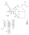
Fig. 1 is a schematic illustration of an embodiment of a system of the present invention for manufacturing an article; and -
Fig. 2 is a flowchart of an embodiment of the method of the present invention for manufacturing an article, which may be carried out using the system shown inFig. 1 . - Referring now to the drawings, and more particularly to
Fig. 1 , there is shown an embodiment of asystem 10 for manufacturing anarticle 12.Article 12 may be any type of manufactured article which is assembled, welded, painted, etc. For example,article 12 could be a transmission, machine frame, etc. For ease of illustration,article 12 is simply shown as a three-dimensional block with dimensions in the X, Y and Z directions. It will be appreciated that the exact size and shape ofarticle 12 may vary. - For a given manufacturing process,
article 12 is assumed to have a number ofdefined locations 14 corresponding to tool activities to be carried out usingtool 16. In the embodiment shown inFig. 1 ,tool 16 is assumed to be a torque gun, and definedlocations 14 are assumed to be the locations of threaded openings inarticle 12 for receiving threaded fasteners, such as bolts. In the case of a spot welding operation, definedlocations 14 could correspond to the spot weld locations. Likewise, in the case of a welding or painting operation requiring movement of a gun, thedefined locations 14 could be used to represent the start and/or termination points for a predefined movement of the gun. - As indicated above,
tool 16 is assumed to be a torque gun in the embodiment shown inFig. 1 . To that end, althoughtool 16 is shown in simplified block form, it will be appreciated that the exterior shape would more closely approximate a typical torque gun.Torque gun 16 includes a rotatably drivensocket 18, which in turn is engaged with and drives the head of a threaded bolt (not shown) placed in a respective threaded hole at a correspondingdefined location 14.Torque gun 16 is coupled with a suitable source of power, such as through anair hose 20 connected to a remote air supply (not shown). It will be appreciated thattorque gun 16 could be electrically driven, in whichcase reference number 20 would correspond to an electrical cable coupled with an electrical power supply. -
Tool 16 could also take the form of other types of portable hand-held tools, such as a torque wrench, weld gun, paint gun, pulse gun, air tool or banding tool. -
Tool 16 also includes one or moreoptical targets 22 which are placed at corresponding exterior locations. In the embodiment shown,tool 16 includes a single optical target in the form of an active target which emanates a particular type of light. Rather than being an active target requiring a source of electrical power (e.g., battery power), it is also possible thattarget 22 could be a passive target such as a number of reflective balls, a reflective strip, a projection with a predefined shape, etc. - An
electrical circuit 24 includes anelectrical processor 26,memory 28, one ormore cameras 30, andfeedback 31.Electrical processor 26 preferably is a microprocessor which is coupled with each ofmemory 28 and camera(s) 30.Electrical processor 26 is hardwired with each ofmemory 28 andcamera 30 in the illustrated embodiment, but could also be coupled via wireless connections, etc. -
Memory 28 is any suitable type of memory capable of long term storage of data which is provided toelectrical processor 26. For example,memory 28 can be used to store the coordinates ofdefined locations 14 onarticle 12. -
Camera 30 is used to detect the actual location ofoptical target 22 ontool 16, and provides corresponding output signals toelectrical processor 26. In the embodiment shown,camera 30 is assumed to be an infrared (IR) camera which detects light which is transmitted fromoptical target 22. Preferably multiple cameras are used at different locations associate with the work station at whicharticle 12 is located so thatoptical target 22 may be more accurately located relative to a known coordinate. -
Feedback 31 is a schematic representation of some type of feedback which is provided to an operator or assembler during the manufacturing process, discussed in more detail below. - Referring now to
Fig. 2 , an embodiment of the method of the present invention for manufacturing an article will be described in greater detail. Initially, the one or more defined locations for carrying out a tool activity are established using data stored in memory 28 (block 40). Ifarticle 12 is accurately placed at a known position and orientation within the work station, then it is possible that the defined locations could simply be three-dimensional, absolute coordinates relative to a known coordinate. Alternatively, it is possible to establish thedefined locations 14 relative to a three-dimensional model ofarticle 12 within the work station. This approach may allow a more dynamic referencing of thedefined locations 14 for a given tool activity relative to the size, shape, exact position and orientation ofarticle 12 within the work station. (i.e., more of a relative rather than absolute determination ofdefined locations 14 on article 12). - In the embodiment shown, a three-dimensional representation of
article 12 is generated and stored within a computer aided drafting (CAD) library withinmemory 28. Eachdefined location 14 is correlated to a corresponding point on the three-dimensional representation ofarticle 12. The three-dimensional coordinate of each correlated point is likewise stored inmemory 28. Additionally, a defined tool activity is assigned for each correlated point on the three-dimensional representation ofarticle 12. The assigned tool activities for each correlated point are likewise stored inmemory 28. Thus, thedefined locations 14 in essence overlie the three-dimensional representation ofarticle 12, and each defined location has a corresponding defined tool activity. - Rather than using a CAD library or numerical analysis technique to establish the
defined locations 14 for a tool activity, it is also possible to empirically establish thedefined locations 14. In particular, the position(s) oftool 16 may be tracked during an initial data gathering stage and correlated with the occurrence of tool activities to establish thedefined locations 14 which are stored withinmemory 28. In the case of a moving tool activity such as welding or painting, a set of detecteddefined locations 14 can be used to define the tool activity. -
Electrical processor 26 uses the output signals fromcamera 30 to determine the actual location of tool 16 (block 42). The actual location is compared with a corresponding defined location for a given tool activity (block 44).Electrical processor 26 then ascertains whether the prescribed tool activity occurred at the actual location (block 46). For example, in the case of a torque gun, it is possible to sense whether the torque which is applied to the head of the bolt reaches a predefined torque value. This information can be sent via a wired or wireless connection toelectrical processor 26. The prescribed tool activity must occur, and the actual location must match with the defined location, in order for the tool activity to be verified (block 48). - At
decision block 50, a determination is made as to whether an operator is to be provided with feedback in the event that the manufacturing process is not proceeding as expected. More particularly, if the tool activity does not correspond to the prescribed tool activity, and the actual location does not match with the defined location, then an operator is provided with feedback (block 52). For example,electrical processor 26 can control the manufacturing process to shut offtool 16, not allowarticle 12 to advance to a next workstation, trigger a warning light observable by the operator and/or generate a written report. The feedback can be positive or negative. For instance, a monitor can be placed in front of an operator with a model of the assembly that has components turning a different color when the activity is completed on that component. This gives the operator visual feedback on what is left to complete, or shows what is next in the sequence if a sequence is required. Other types of feedback are of course also possible. - On the other hand, if the tool activity does correspond to the expected tool activity, and the actual location matches with the defined location, then there is no need to provide feedback to an operator (line 54).
- At
decision block 56, a determination is made as to whethertool 16 should be moved to additional definedlocations 14 for further tool activities. If so, then control loops to block 42 and the control logic repeats. On the other hand, if there is only a single defined location for a tool activity, ortool 16 is at the defined location corresponding to a last tool activity, then the control logic simply ends. - For an article having multiple defined locations with corresponding tool activities at each defined location, it is possible to track the actual locations and/or tool activities at each actual location for various purposes. For example, one purpose for tracking the actual locations and tool activities at each actual location is to identify the
particular article 12 which is being manufactured. This allowselectrical processor 26 to know the sequence of the remaining defined locations and corresponding tool activities which are to occur after thearticle 12 is identified. If an operator does not perform a next expected tool activity for a givenarticle 12, then feedback may be provided to the operator atblock 52. - From the foregoing description, it is apparent that the method and system of the present invention dynamically avoids mistakes during the manufacturing process by tracking the position and operation of
tool 16 relative to a predetermined or dynamically identifiedarticle 12. - In the
system 10 for manufacturing an article described above, a location detector detects the position oftool 16 usingcamera 30 andoptical target 22.Optical target 22 thus in essence is a passive component, the position of which is sensed using one ormore cameras 30.Cameras 30 are therefore the active components providing output signals toelectrical processor 26. It is also possible to configuresystem 10 with a location detector having an active component ontool 16 which provides an output signal toelectrical processor 26 to determine the actual location oftool 16. For example,tool 16 may include a location detector in the form of an active sensor which senses its position relative to a fixed coordinate and transmits a wireless signal toelectrical processor 26.
Claims (15)
- A method of manufacturing an article (12), comprising the steps of:establishing a defined location (14) for a tool activity to occur;determining an actual location of the tool (16);comparing said actual location of the tool (16) with said defined location (14); ascertaining an occurrence of said tool (16) activity at said actual location; andverifying whether said tool activity occurred at said defined location.
- The method of manufacturing an article of claim 1, including the steps of:repeating for at least one other defined location each of said establishing, determining, comparing, ascertaining and verifying steps; andstoring data for each said defined location (14), said corresponding actual location, and said corresponding tool activity.
- The method of manufacturing an article of claim 2, including the step of tracking said actual locations based upon said stored data and/or said tool activities based upon said stored data.
- The method of manufacturing an article of claim 2, including the step of identifying the article (12) based upon said stored data.
- The method of manufacturing an article of claim 4, including the step of correlating each said defined location to a point on the identified article (12).
- The method of manufacturing an article of claim 2, wherein said defined locations are established using one of a CAD model, a numerical analysis technique, and an empirical analysis.
- The method of manufacturing an article of claim 2, including the steps of:generating a 3-dimensional representation of the article (12) to be assembled;correlating each said defined location to a point on said 3-dimensional representation;assigning a defined tool activity to each correlated point on said 3-dimensional representation; andcomparing each said defined tool activity at each correlated point with said tool activity at said actual location.
- The method of manufacturing an article of claim 2, including the step of providing feedback to an operator dependent upon said steps of verifying whether said tool activities occurred at said corresponding defined locations.
- The method of manufacturing an article of claim 8, wherein said feedback includes one of:shutting off the tool;not allowing the article to advance to a next work station;triggering a warning light; andgenerating a report.
- The method of manufacturing an article of claim 1, wherein said step of determining an actual location of the tool (16) is carried out using an optical target (22) on the tool (16) and at least one camera (30), said at least one camera (30) determining a location of the optical target (22) relative to a known coordinate.
- The method of manufacturing an article of claim 10, wherein said optical target (22) is one of an active target and an inactive target.
- The method of manufacturing an article of claim 1, wherein said tool (16) is a hand-held portable tool, for example at least one of a torque gun, a torque wrench, a weld gun, a paint gun, a pulse gun, an air tool, and a banding tool.
- The method of manufacturing an article of claim 1, including the step of providing feedback to an operator dependent upon said step of verifying whether said tool activity occurred at said defined location, wherein said feedback preferably includes one of:shutting off the tool;not allowing the article to advance to a next work station;triggering a warning light;displaying completed work on a model; andgenerating a report.
- A system (10) for manufacturing an article (12), comprising:a memory (28) configured for storing a defined location (14) for a tool activity to occur;a location detector for detecting an actual location of said tool (16); andan electrical processor (26) in communication with each of said memory (28) and said location detector, said electrical processor (26) being configured for comparing said actual location of the tool (16) with said defined location (14), ascertaining an occurrence of said tool activity at said actual location; and verifying whether said tool activity occurred at said defined location.
- The system (10) for manufacturing an article of claim 14, wherein:said memory (28) is configured for storing a plurality of defined locations for respective said tool activities to occur;said location detector is configured for detecting a plurality of actual locations of said tool (16); andsaid electrical processor (26) is configured for comparing said actual locations of the tool (16) with respective said defined locations (14), ascertaining an occurrence of said tool activity at each said actual location, and verifying whether each said tool activity occurred at a respective said defined location.
Applications Claiming Priority (1)
| Application Number | Priority Date | Filing Date | Title |
|---|---|---|---|
| US12/022,230 US20090192644A1 (en) | 2008-01-30 | 2008-01-30 | Method and system for manufacturing an article using portable hand-held tools |
Publications (3)
| Publication Number | Publication Date |
|---|---|
| EP2085849A2 true EP2085849A2 (en) | 2009-08-05 |
| EP2085849A3 EP2085849A3 (en) | 2010-02-24 |
| EP2085849B1 EP2085849B1 (en) | 2014-03-12 |
Family
ID=40723153
Family Applications (1)
| Application Number | Title | Priority Date | Filing Date |
|---|---|---|---|
| EP09151025.5A Active EP2085849B1 (en) | 2008-01-30 | 2009-01-21 | Method and system for manufacturing an article using portable hand-held tools |
Country Status (4)
| Country | Link |
|---|---|
| US (1) | US20090192644A1 (en) |
| EP (1) | EP2085849B1 (en) |
| BR (1) | BRPI0900060B1 (en) |
| ES (1) | ES2471455T3 (en) |
Cited By (11)
| Publication number | Priority date | Publication date | Assignee | Title |
|---|---|---|---|---|
| WO2011049862A1 (en) * | 2009-10-19 | 2011-04-28 | Fives Cinetics Inc. | System and method for optimizing a production process using electromagnetic-based local positioning capabilities |
| FR2965203A1 (en) * | 2010-09-27 | 2012-03-30 | Peugeot Citroen Automobiles Sa | Workstation for assembly line for performing assembling operations of component of motor vehicle, has determination unit determining adequacy of located tool and its position, and prevention unit preventing inadequate assembling operation |
| GB2486658A (en) * | 2010-12-21 | 2012-06-27 | Crane Electronics | Torque tool positioning system |
| GB2508090A (en) * | 2012-11-09 | 2014-05-21 | Hitachi Ltd | Operation management system for displaying and recording completion of operations |
| EP2538297A3 (en) * | 2011-06-24 | 2016-10-19 | The Boeing Company | Manufacturing control system |
| DE202015106588U1 (en) * | 2015-12-03 | 2016-12-08 | Homag Gmbh | processing station |
| FR3076234A1 (en) * | 2017-12-29 | 2019-07-05 | Altran Technologies - Altran | SYSTEM FOR LOCATING A TOOL IN RELATION TO A SURFACE |
| EP3705958A1 (en) * | 2019-03-06 | 2020-09-09 | The Boeing Company | Tool orientation systems and methods |
| US11103980B2 (en) | 2018-10-12 | 2021-08-31 | Ingersoll-Rand Industrial U.S., Inc. | Assembly tool smart configuration selector by means of orientation detection |
| EP4345555A1 (en) * | 2022-09-30 | 2024-04-03 | Murrelektronik GmbH | A method for computer-assisted verification and documentation of a user's installation action for installing decentralised components of a machine |
| WO2024068741A1 (en) * | 2022-09-30 | 2024-04-04 | Murrelektronik Gmbh | Method for computer-supported testing and documenting of an installation operation of a user for the installation of spatially decentralised components of a machine |
Families Citing this family (24)
| Publication number | Priority date | Publication date | Assignee | Title |
|---|---|---|---|---|
| US9256220B1 (en) | 2008-06-25 | 2016-02-09 | The Boeing Company | System and method for monitoring completed manufacturing operations |
| US8311658B2 (en) * | 2008-06-25 | 2012-11-13 | The Boeing Company | System and method for monitoring completed manufacturing operations |
| PL2458367T3 (en) * | 2010-11-25 | 2015-12-31 | Mettler Toledo Gmbh | Device and method for recognising solid substances in a liquid phase |
| US8700202B2 (en) * | 2010-11-30 | 2014-04-15 | Trimble Navigation Limited | System for positioning a tool in a work space |
| EP2809482B1 (en) * | 2012-01-30 | 2018-11-07 | Fatigue Technology, Inc. | Processing systems and method of operating the same |
| DE102013203397A1 (en) * | 2012-06-29 | 2014-01-02 | Robert Bosch Gmbh | Control of a battery powered handset |
| US9340304B2 (en) | 2013-02-28 | 2016-05-17 | The Boeing Company | Aircraft comparison system |
| US9292180B2 (en) | 2013-02-28 | 2016-03-22 | The Boeing Company | Locator system for three-dimensional visualization |
| US9880694B2 (en) | 2013-05-09 | 2018-01-30 | The Boeing Company | Shop order status visualization system |
| US10481768B2 (en) | 2013-04-12 | 2019-11-19 | The Boeing Company | Nonconformance identification and visualization system and method |
| US9870444B2 (en) * | 2013-03-05 | 2018-01-16 | The Boeing Company | Shop order status visualization system |
| US10067650B2 (en) | 2013-06-20 | 2018-09-04 | The Boeing Company | Aircraft comparison system with synchronized displays |
| US9612725B1 (en) | 2013-02-28 | 2017-04-04 | The Boeing Company | Nonconformance visualization system |
| US9492900B2 (en) | 2013-03-15 | 2016-11-15 | The Boeing Company | Condition of assembly visualization system based on build cycles |
| US10061481B2 (en) | 2013-02-28 | 2018-08-28 | The Boeing Company | Methods and devices for visually querying an aircraft based on an area of an image |
| US20140298216A1 (en) | 2013-03-28 | 2014-10-02 | The Boeing Company | Visualization of an Object Using a Visual Query System |
| US10416857B2 (en) | 2013-05-09 | 2019-09-17 | The Boeing Company | Serial number control visualization system |
| US9342070B2 (en) * | 2013-05-31 | 2016-05-17 | Autoform Engineering Gmbh | Method and computing system for designing a sheet-metal-forming process |
| JP6486005B2 (en) * | 2014-01-17 | 2019-03-20 | 蛇の目ミシン工業株式会社 | Robot, robot control method, and robot control program |
| JP6399437B2 (en) | 2014-06-04 | 2018-10-03 | パナソニックIpマネジメント株式会社 | Control device and work management system using the same |
| US10685147B2 (en) | 2016-02-29 | 2020-06-16 | The Boeing Company | Non-conformance mapping and visualization |
| JP6929537B2 (en) * | 2017-05-31 | 2021-09-01 | 株式会社フジキン | How to assemble work assistance system, work assistance device, and valve |
| DE102018127518A1 (en) | 2018-11-05 | 2020-05-07 | Advanced Realtime Tracking Gmbh | Device and method for processing at least one work area with a processing tool |
| WO2020254353A1 (en) * | 2019-06-20 | 2020-12-24 | Atlas Copco Industrial Technique Ab | Portable socket holder for sockets or bits connecteable to a power tool |
Citations (2)
| Publication number | Priority date | Publication date | Assignee | Title |
|---|---|---|---|---|
| US20020032956A1 (en) | 2001-11-19 | 2002-03-21 | Lms-Walt, Inc. | Assembly system for monitoring proper fastening of an article of assembly at more than one location |
| US20020038159A1 (en) | 1998-09-21 | 2002-03-28 | Baltes Gass | Process system and process tool for processing a workpiece |
Family Cites Families (34)
| Publication number | Priority date | Publication date | Assignee | Title |
|---|---|---|---|---|
| US3886421A (en) * | 1973-09-10 | 1975-05-27 | Ibm | Precision tool and workpiece positioning apparatus with ringout detection |
| US4131837A (en) * | 1976-11-10 | 1978-12-26 | The Boeing Company | Machine tool monitoring system |
| US5207554A (en) * | 1982-09-21 | 1993-05-04 | Fujitsu Limited | Supporting device |
| US5426722A (en) * | 1993-09-09 | 1995-06-20 | Stratasys, Inc. | Method for optimizing the motion of a multi-axis robot |
| US5521480A (en) * | 1994-09-01 | 1996-05-28 | Gerber Scientific Products, Inc. | Apparatus and method for defining a reference position of a tool |
| US6516130B1 (en) * | 1998-12-30 | 2003-02-04 | Newport Corporation | Clip that aligns a fiber optic cable with a laser diode within a fiber optic module |
| US6205364B1 (en) * | 1999-02-02 | 2001-03-20 | Creo Ltd. | Method and apparatus for registration control during processing of a workpiece particularly during producing images on substrates in preparing printed circuit boards |
| US6136370A (en) * | 1999-07-16 | 2000-10-24 | Morton International, Inc. | Method of powder coating a substrate |
| US6308787B1 (en) * | 1999-09-24 | 2001-10-30 | Vermeer Manufacturing Company | Real-time control system and method for controlling an underground boring machine |
| DE19955646A1 (en) * | 1999-11-19 | 2001-06-13 | Bayerische Motoren Werke Ag | Device and method for assigning a tool to a workpiece |
| GB0004455D0 (en) * | 2000-02-26 | 2000-04-19 | Glaxo Group Ltd | Manufacturing method |
| KR100345150B1 (en) * | 2000-09-29 | 2002-07-24 | 현대자동차주식회사 | Method for compensating robot position using laser analyzer |
| US6384364B1 (en) * | 2000-12-21 | 2002-05-07 | General Electric Company | Method of aligning electrode in multiple-axis EDM drilling |
| US6455800B1 (en) * | 2001-01-04 | 2002-09-24 | Festo Corporation | Servo-pneumatic modular weld gun |
| US7055789B2 (en) * | 2002-05-14 | 2006-06-06 | Automation Tool Company | Articulating tool arm with positional feedback |
| GB0220460D0 (en) * | 2002-09-03 | 2002-10-09 | Acrobot Company The Ltd | Robot head |
| ES2274320T3 (en) * | 2002-12-18 | 2007-05-16 | Fraunhofer-Gesellschaft Zur Forderung Der Angewandten Forschung E.V. | PROCEDURE TO EVALUATE A SOLDED UNION THAT IS BEING FORMED DURING A WELDING PROCESS WITH LONGITUDINAL AND TRANSVERSAL ULTRASOUND WAVES. |
| SE524818C2 (en) * | 2003-02-13 | 2004-10-05 | Abb Ab | A method and system for programming an industrial robot to move relatively defined positions on an object |
| US7107125B2 (en) * | 2003-10-29 | 2006-09-12 | Applied Materials, Inc. | Method and apparatus for monitoring the position of a semiconductor processing robot |
| US6845279B1 (en) * | 2004-02-06 | 2005-01-18 | Integrated Technologies, Inc. | Error proofing system for portable tools |
| DE102004013615A1 (en) * | 2004-03-19 | 2005-10-13 | Siemens Ag | Operating method for a machine tool controlled by a control device |
| EP1586421B1 (en) * | 2004-04-16 | 2008-03-05 | Honda Research Institute Europe GmbH | Self-calibrating orienting system for a manipulating device |
| US20050246064A1 (en) * | 2004-04-29 | 2005-11-03 | Smith Gregory C | Method for detecting position errors using a motion detector |
| US7315252B2 (en) * | 2004-05-04 | 2008-01-01 | Automated Solutions | Assembly machine operator interface with multiple color light indicators |
| US7490664B2 (en) * | 2004-11-12 | 2009-02-17 | Halliburton Energy Services, Inc. | Drilling, perforating and formation analysis |
| WO2006059927A1 (en) * | 2004-11-30 | 2006-06-08 | Atlas Copco Tools Ab | System for identifying different working positions of a portable power tool and for monitoring and governing the operation of a power tool |
| GB0513899D0 (en) * | 2005-07-06 | 2005-08-10 | Airbus Uk Ltd | Program-controlled process |
| US7366583B2 (en) * | 2005-09-01 | 2008-04-29 | General Electric Company | Methods and systems for fabricating components |
| US8782878B2 (en) * | 2005-09-28 | 2014-07-22 | Nikon Metrology Nv | Fastener automation system |
| US8065060B2 (en) * | 2006-01-18 | 2011-11-22 | The Board Of Regents Of The University And Community College System On Behalf Of The University Of Nevada | Coordinated joint motion control system with position error correction |
| US20070188606A1 (en) * | 2006-02-16 | 2007-08-16 | Kevin Atkinson | Vision-based position tracking system |
| US7974737B2 (en) * | 2006-10-31 | 2011-07-05 | GM Global Technology Operations LLC | Apparatus and method of automated manufacturing |
| US20080221733A1 (en) * | 2007-03-07 | 2008-09-11 | Kmt Robotic Solutions, Inc. | System and method of locating relative positions of objects |
| US8082064B2 (en) * | 2007-08-24 | 2011-12-20 | Elite Engineering Corporation | Robotic arm and control system |
-
2008
- 2008-01-30 US US12/022,230 patent/US20090192644A1/en not_active Abandoned
-
2009
- 2009-01-19 BR BRPI0900060-7A patent/BRPI0900060B1/en active IP Right Grant
- 2009-01-21 ES ES09151025.5T patent/ES2471455T3/en active Active
- 2009-01-21 EP EP09151025.5A patent/EP2085849B1/en active Active
Patent Citations (2)
| Publication number | Priority date | Publication date | Assignee | Title |
|---|---|---|---|---|
| US20020038159A1 (en) | 1998-09-21 | 2002-03-28 | Baltes Gass | Process system and process tool for processing a workpiece |
| US20020032956A1 (en) | 2001-11-19 | 2002-03-21 | Lms-Walt, Inc. | Assembly system for monitoring proper fastening of an article of assembly at more than one location |
Cited By (18)
| Publication number | Priority date | Publication date | Assignee | Title |
|---|---|---|---|---|
| CN102695992B (en) * | 2009-10-19 | 2015-11-25 | 费福思塞奈提科斯有限公司 | The local positioning ability based on electromagnetism is utilized to optimize the system and method for production run |
| CN102695992A (en) * | 2009-10-19 | 2012-09-26 | 费福思塞奈提科斯有限公司 | System and method for optimizing a production process using electromagnetic-based local positioning capabilities |
| US8676368B2 (en) | 2009-10-19 | 2014-03-18 | Fives Cinetic Inc. | System and method for optimizing a production process using electromagnetic-based local positioning capabilities |
| WO2011049862A1 (en) * | 2009-10-19 | 2011-04-28 | Fives Cinetics Inc. | System and method for optimizing a production process using electromagnetic-based local positioning capabilities |
| FR2965203A1 (en) * | 2010-09-27 | 2012-03-30 | Peugeot Citroen Automobiles Sa | Workstation for assembly line for performing assembling operations of component of motor vehicle, has determination unit determining adequacy of located tool and its position, and prevention unit preventing inadequate assembling operation |
| GB2486658A (en) * | 2010-12-21 | 2012-06-27 | Crane Electronics | Torque tool positioning system |
| EP2538297A3 (en) * | 2011-06-24 | 2016-10-19 | The Boeing Company | Manufacturing control system |
| GB2508090B (en) * | 2012-11-09 | 2015-01-28 | Hitachi Ltd | Operation management system for displaying and recording completion of operations |
| GB2508090A (en) * | 2012-11-09 | 2014-05-21 | Hitachi Ltd | Operation management system for displaying and recording completion of operations |
| DE202015106588U1 (en) * | 2015-12-03 | 2016-12-08 | Homag Gmbh | processing station |
| FR3076234A1 (en) * | 2017-12-29 | 2019-07-05 | Altran Technologies - Altran | SYSTEM FOR LOCATING A TOOL IN RELATION TO A SURFACE |
| US11103980B2 (en) | 2018-10-12 | 2021-08-31 | Ingersoll-Rand Industrial U.S., Inc. | Assembly tool smart configuration selector by means of orientation detection |
| US20210394342A1 (en) * | 2018-10-12 | 2021-12-23 | Ingersoll-Rand Industrial U.S., Inc. | Assembly tool smart configuration selector by means of orientation detection |
| US11890725B2 (en) * | 2018-10-12 | 2024-02-06 | Ingersoll-Rand Industrial U.S., Inc. | Assembly tool smart configuration selector by means of orientation detection |
| EP3705958A1 (en) * | 2019-03-06 | 2020-09-09 | The Boeing Company | Tool orientation systems and methods |
| US11947330B2 (en) | 2019-03-06 | 2024-04-02 | The Boeing Company | Tool orientation systems and methods |
| EP4345555A1 (en) * | 2022-09-30 | 2024-04-03 | Murrelektronik GmbH | A method for computer-assisted verification and documentation of a user's installation action for installing decentralised components of a machine |
| WO2024068741A1 (en) * | 2022-09-30 | 2024-04-04 | Murrelektronik Gmbh | Method for computer-supported testing and documenting of an installation operation of a user for the installation of spatially decentralised components of a machine |
Also Published As
| Publication number | Publication date |
|---|---|
| US20090192644A1 (en) | 2009-07-30 |
| BRPI0900060A2 (en) | 2009-09-22 |
| EP2085849B1 (en) | 2014-03-12 |
| EP2085849A3 (en) | 2010-02-24 |
| ES2471455T3 (en) | 2014-06-26 |
| BRPI0900060B1 (en) | 2019-02-26 |
Similar Documents
| Publication | Publication Date | Title |
|---|---|---|
| EP2085849B1 (en) | Method and system for manufacturing an article using portable hand-held tools | |
| EP2916189B1 (en) | Quality assured manufacturing | |
| US10528036B2 (en) | Light guided assembly system and method | |
| JP5022045B2 (en) | System, work cell, method, product manufacturing method, and marker for specifying work position | |
| EP1607194B1 (en) | Robot system comprising a plurality of robots provided with means for calibrating their relative position | |
| JP5574202B2 (en) | Work robot support system | |
| CN102695992B (en) | The local positioning ability based on electromagnetism is utilized to optimize the system and method for production run | |
| US20210402613A1 (en) | Method for the control of a processing machine or of an industrial robot | |
| US20160048122A1 (en) | Arrangement and Method for Monitoring a Position of a Hand-Held Tool | |
| US12558746B2 (en) | Monitoring system employing smart gloves to analyze operator fabrication activities | |
| EP3705958B1 (en) | Tool orientation systems and methods | |
| CN111702306A (en) | Time-of-flight camera for welding machine vision | |
| GB2486658A (en) | Torque tool positioning system | |
| US10482589B2 (en) | Method and apparatus for the start-up operation of a multi-axis system | |
| WO2021086327A1 (en) | System and method for robotic evaluation | |
| CN117260776A (en) | A human-computer interaction method and device applied to robots | |
| TWI725630B (en) | Processing path generating device and method thereof | |
| Settimi et al. | Augmented Carpentry: Computer vision-assisted framework for manual fabrication | |
| KR100588505B1 (en) | Robot Position Correction Control Device and Method | |
| JP2005177919A (en) | Work tool and work system using the same | |
| CN113840692B (en) | Control of manual operations using portable hand tools in the production of component assemblies | |
| CN103009388B (en) | Light wave transmitter as well as robot track locating system and robot track locating method | |
| CN202943639U (en) | Light wave emitter and robot trajectory seeking system | |
| JPH11102209A (en) | Method and device for collecting work teaching point position data | |
| Rzeznik | In‐line laser measurement in the assembly process |
Legal Events
| Date | Code | Title | Description |
|---|---|---|---|
| PUAI | Public reference made under article 153(3) epc to a published international application that has entered the european phase |
Free format text: ORIGINAL CODE: 0009012 |
|
| AK | Designated contracting states |
Kind code of ref document: A2 Designated state(s): AT BE BG CH CY CZ DE DK EE ES FI FR GB GR HR HU IE IS IT LI LT LU LV MC MK MT NL NO PL PT RO SE SI SK TR |
|
| AX | Request for extension of the european patent |
Extension state: AL BA RS |
|
| PUAL | Search report despatched |
Free format text: ORIGINAL CODE: 0009013 |
|
| AK | Designated contracting states |
Kind code of ref document: A3 Designated state(s): AT BE BG CH CY CZ DE DK EE ES FI FR GB GR HR HU IE IS IT LI LT LU LV MC MK MT NL NO PL PT RO SE SI SK TR |
|
| AX | Request for extension of the european patent |
Extension state: AL BA RS |
|
| 17P | Request for examination filed |
Effective date: 20100824 |
|
| 17Q | First examination report despatched |
Effective date: 20100917 |
|
| AKX | Designation fees paid |
Designated state(s): DE ES FR |
|
| GRAP | Despatch of communication of intention to grant a patent |
Free format text: ORIGINAL CODE: EPIDOSNIGR1 |
|
| INTG | Intention to grant announced |
Effective date: 20131023 |
|
| GRAS | Grant fee paid |
Free format text: ORIGINAL CODE: EPIDOSNIGR3 |
|
| GRAA | (expected) grant |
Free format text: ORIGINAL CODE: 0009210 |
|
| AK | Designated contracting states |
Kind code of ref document: B1 Designated state(s): DE ES FR |
|
| REG | Reference to a national code |
Ref country code: DE Ref legal event code: R096 Ref document number: 602009022338 Country of ref document: DE Effective date: 20140424 |
|
| REG | Reference to a national code |
Ref country code: ES Ref legal event code: FG2A Ref document number: 2471455 Country of ref document: ES Kind code of ref document: T3 Effective date: 20140626 |
|
| REG | Reference to a national code |
Ref country code: DE Ref legal event code: R097 Ref document number: 602009022338 Country of ref document: DE |
|
| PLBE | No opposition filed within time limit |
Free format text: ORIGINAL CODE: 0009261 |
|
| STAA | Information on the status of an ep patent application or granted ep patent |
Free format text: STATUS: NO OPPOSITION FILED WITHIN TIME LIMIT |
|
| REG | Reference to a national code |
Ref country code: FR Ref legal event code: PLFP Year of fee payment: 7 |
|
| 26N | No opposition filed |
Effective date: 20141215 |
|
| REG | Reference to a national code |
Ref country code: DE Ref legal event code: R097 Ref document number: 602009022338 Country of ref document: DE Effective date: 20141215 |
|
| PGFP | Annual fee paid to national office [announced via postgrant information from national office to epo] |
Ref country code: ES Payment date: 20150126 Year of fee payment: 7 |
|
| PGFP | Annual fee paid to national office [announced via postgrant information from national office to epo] |
Ref country code: FR Payment date: 20150119 Year of fee payment: 7 |
|
| REG | Reference to a national code |
Ref country code: FR Ref legal event code: ST Effective date: 20160930 |
|
| PG25 | Lapsed in a contracting state [announced via postgrant information from national office to epo] |
Ref country code: FR Free format text: LAPSE BECAUSE OF NON-PAYMENT OF DUE FEES Effective date: 20160201 |
|
| REG | Reference to a national code |
Ref country code: ES Ref legal event code: FD2A Effective date: 20170227 |
|
| PG25 | Lapsed in a contracting state [announced via postgrant information from national office to epo] |
Ref country code: ES Free format text: LAPSE BECAUSE OF NON-PAYMENT OF DUE FEES Effective date: 20160122 |
|
| PGFP | Annual fee paid to national office [announced via postgrant information from national office to epo] |
Ref country code: DE Payment date: 20251219 Year of fee payment: 18 |