EP2085747A1 - Portable laser projector and enclosure - Google Patents
Portable laser projector and enclosure Download PDFInfo
- Publication number
- EP2085747A1 EP2085747A1 EP08253271A EP08253271A EP2085747A1 EP 2085747 A1 EP2085747 A1 EP 2085747A1 EP 08253271 A EP08253271 A EP 08253271A EP 08253271 A EP08253271 A EP 08253271A EP 2085747 A1 EP2085747 A1 EP 2085747A1
- Authority
- EP
- European Patent Office
- Prior art keywords
- purge chamber
- laser projector
- laser
- optically transparent
- transparent wall
- Prior art date
- Legal status (The legal status is an assumption and is not a legal conclusion. Google has not performed a legal analysis and makes no representation as to the accuracy of the status listed.)
- Granted
Links
Images



Classifications
-
- G—PHYSICS
- G01—MEASURING; TESTING
- G01C—MEASURING DISTANCES, LEVELS OR BEARINGS; SURVEYING; NAVIGATION; GYROSCOPIC INSTRUMENTS; PHOTOGRAMMETRY OR VIDEOGRAMMETRY
- G01C15/00—Surveying instruments or accessories not provided for in groups G01C1/00 - G01C13/00
- G01C15/002—Active optical surveying means
-
- G—PHYSICS
- G03—PHOTOGRAPHY; CINEMATOGRAPHY; ANALOGOUS TECHNIQUES USING WAVES OTHER THAN OPTICAL WAVES; ELECTROGRAPHY; HOLOGRAPHY
- G03B—APPARATUS OR ARRANGEMENTS FOR TAKING PHOTOGRAPHS OR FOR PROJECTING OR VIEWING THEM; APPARATUS OR ARRANGEMENTS EMPLOYING ANALOGOUS TECHNIQUES USING WAVES OTHER THAN OPTICAL WAVES; ACCESSORIES THEREFOR
- G03B21/00—Projectors or projection-type viewers; Accessories therefor
- G03B21/14—Details
- G03B21/18—Fire preventing or extinguishing
-
- H—ELECTRICITY
- H01—ELECTRIC ELEMENTS
- H01S—DEVICES USING THE PROCESS OF LIGHT AMPLIFICATION BY STIMULATED EMISSION OF RADIATION [LASER] TO AMPLIFY OR GENERATE LIGHT; DEVICES USING STIMULATED EMISSION OF ELECTROMAGNETIC RADIATION IN WAVE RANGES OTHER THAN OPTICAL
- H01S3/00—Lasers, i.e. devices using stimulated emission of electromagnetic radiation in the infrared, visible or ultraviolet wave range
- H01S3/02—Constructional details
- H01S3/025—Constructional details of solid state lasers, e.g. housings or mountings
- H01S3/027—Constructional details of solid state lasers, e.g. housings or mountings comprising a special atmosphere inside the housing
Definitions
- the present disclosure is generally related to a laser projector and more particularly is related to a portable laser projector and enclosure for use in hazardous environments.
- Laser projection is a useful tool in manufacturing processes.
- Laser projectors can be used for non-contact vision Inspection and visual pattern guidance.
- Laser projections are used extensively in composite ply construction for aircraft manufacturing. Rapid kitting is accomplished using laser projection to indicate locations of numerous small items on large sheets of stock. Nested parts are often cut in separate areas of a large sheet to optimize material usage. Consequently, the parts for one kit may be grouped with the parts to another.
- Laser projectors are used to highlight parts in sequence for kitting. Names, kit numbers and other nomenclature may also be projected.
- Laser projection can eliminate the need for costly tooling, templates or layouts. The ability to view the exact location of an object without the use of additional tooling results in cost savings.
- Laser projected shapes can assist in outlining designs on large objects, such as planes, buses, boats and trains, for paint masking. Current methods require extensive measuring and can be painstaking and time consuming.
- Laser projection can provide an accurate reference line on objects for paint masking applications.
- paint booths present a problem in that various hazardous and explosive gases are associated with paint booths. Association of laser projectors with paint booths is considered a safety risk, deterring realization of the prospective cost savings of laser projection templates for paint masking.
- Embodiments of the present disclosure provide a system and method for laser projection in an explosive environment. Briefly described, in architecture, one embodiment of the system, among others, can be implemented as follows.
- the system contains a purge chamber.
- a substantially optically transparent wall is formed along the purge chamber.
- a laser projector is mounted within the purge chamber. The laser projector is positioned to project a laser beam through the substantially optically transparent wall.
- the present disclosure can also be viewed as providing methods for providing laser projection in an explosive environment.
- one embodiment of such a method can be broadly summarized by the following steps: projecting an image onto an object with a laser projector; operating the laser projector from within a purge chamber; projecting the image through a substantially optically transparent wall of the purge chamber; and controlling an environment within the purge chamber.
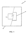
- FIG. 1 is an illustration of a partial cut-away front of a system 10 for laser projection in an explosive environment, in accordance with a first exemplary embodiment.
- the system 10 contains a purge chamber 12.
- a substantially optically transparent wall 14 is formed along the purge chamber 12.
- a laser projector 16 is mounted within the purge chamber 12. The laser projector 16 is positioned to project a laser beam through the substantially optically transparent wall 14.
- the purge chamber 12 maintains a positive pressure environment within the purge chamber 12 that allows for safe operation of the laser projector 16.
- the purge chamber 12 may be connected to one or more conduits that transmit one or more gasses into and out of the purge chamber 12.
- the purge chamber 12 may have one or more monitors housed therein that monitor the environment within the purge chamber 12 for the presence of hazardous or explosive gasses.
- the purge chamber 12 may include a device for communicating to a user the presence of hazardous or explosive gasses in the environment within the purge chamber 12 and/or automatically terminating operation of the laser projector 16 upon indication of the presence of hazardous or explosive gasses.
- the substantially optically transparent wall 14 forms a window that allows the laser projector 16 to project a line, image, or other projection out of the purge chamber 12.
- the substantially optically transparent wall 14 may be designed of a material that allows at least partial passage of the radiation emitted from the laser projector 16. Thus, for example, if the laser projector projects a non-visible wavelength of radiation, the substantially optically transparent wall 14 need only allow transmission of that non-visible wavelength of radiation, although the substantially optically transparent wall 14 may allow transmission of a broad band of radiation wavelengths.
- the laser projector 16 may be any device known in the industry for transmitting one or more beams of radiation.
- the laser projector 16 may include hardware and software for accurately projecting images onto uneven, three dimensional objects.
- FIG. 2 is a perspective illustration of a system 110 for laser projection in an explosive environment, in accordance with a second exemplary embodiment.
- the system 110 contains a purge chamber 112.
- a substantially optically transparent wall 114 is formed along the purge chamber 112.
- a laser projector 116 is mounted within the purge chamber 112.
- the laser projector 116 (shown in FIG. 5 ) is positioned to project a laser beam through the substantially optically transparent wall 114.
- FIG. 3 is a front illustration of the system 110 for laser projection in an explosive environment shown in FIG. 2 , in accordance with the second exemplary embodiment.
- the system 110 includes a protective wall 118 movable between a first position (shown in FIG. 3 ) and a second position (shown in FIG. 2 ), wherein the first position substantially overlaps the substantially optically transparent wall 114 and the second position substantially exposes the substantially optically transparent wall 114.
- the protective wall 118 may be utilized when practical to protect the substantially optically transparent wall 114.
- Protective wall 118 may open and close automatically upon activation of the laser projector.
- the system 110 includes a cart 122 having a plurality of wheels 124, wherein the purge chamber 112 is mounted to the cart 122.
- the cart 122 allows the purge chamber 112 to be rolled to various locations for use of the laser projector 116.
- Cart 122 also includes at least one, and preferably three hand cranked leveling jacks for leveling the cart and lifting the cart to a stable position off the wheels once the cart is moved to a desired position.
- the system 110 includes at least one pivot pin 126 mounted to an exterior surface of the purge chamber 112.
- the purge chamber 112 may have pivot pins 126 on opposing sides of the purge chamber 112.
- the purge chamber 112 may be rotated, for instance, ninety degrees on the pivot pins 126.
- the pivot pins 126 may also be used to pick up the purge chamber 112 with a forklift.
- at least one fork pocket may be formed in the purge chamber 112.
- the fork pocket may be sized to receive a fork of a forklift, allowing the purge chamber 112 to be lifted with the forklift.
- the system 110 includes a wireless communications device 136 (shown in FIG. 5 ) mounted within the purge chamber 112 and wired to the laser projector 116.
- the wireless communications device 136 allows communications to the laser projector 116 through the purge chamber 112.
- the system 110 may include an antenna 138 mounted to the purge chamber 112 at least partially exterior to the purge chamber 112.
- the antenna 138 is in communication with the wireless communications device 136 and may provide enhanced transmission of a signal from the wireless communications device 136.
- the wireless communications device 136 and antenna 138 may be commercially available wireless communications products.
- the wireless communications device 136 may be integral with antenna 138.
- the wireless communications device 136 may, for instance, be used to transmit images to the laser projector 116 for projection.
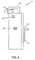
- FIG. 4 is a side illustration of the system for laser projection in an explosive environment shown in FIG. 2 , in accordance with the second exemplary embodiment.
- a conduit 140 is connected to the purge chamber 112 for gas transmission.
- the conduit 140 is shown connected to the purge chamber 112 through a purge controller 142 mounted to the purge chamber 112.
- the purge controller 142 controls gas transmission through the conduit 140.
- the purge controller 142 may also have a release valve 144 ( FIG. 3 ) mounted thereto. The release valve 144 may be operated to release an excess of gas pressure within the purge chamber 112.
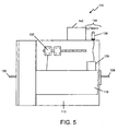
- FIG. 5 is a sectional illustration of the system for laser projection in an explosive environment shown in FIG. 2 , in accordance with the second exemplary embodiment.
- the system 110 includes at least one data connector 128 (shown in FIG. 4 ) and at least one power connector formed in the purge chamber 112 to provide power and communications to the laser projector 116.
- a power strip 132 may be mounted within the purge chamber 112 for connection to the laser projector 116.
- the second exemplary embodiment also shows devices for wireless communication to the laser projector 116 and, while both devices may be provided, it may be more likely that either wired or wireless communication to the laser projector 116 be provided.
- FIG. 6 is an exploded illustration of a portion of the system for laser projection in an explosive environment shown in FIG. 2 , in accordance with the second exemplary embodiment.
- the protective wall 118 may be slidable on a pair of tracks 120.
- the protective wall 118 may be attached to the purge chamber 112 in various other ways, which allow the protective wall 118 to move between a position protecting the substantially optically transparent wall 114 and a position that does not obstruct it.
- Those other ways to attach the protective wall 118 may include devices that allow the protective wall 118 to remain attached to the purge chamber 112, such as hinges, and devices that allow removal of the protective wall 118 from the purge chamber 112, such as a threaded fastening.
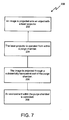
- FIG. 7 is a flowchart 200 illustrating a method of providing the abovementioned system for laser projection in an explosive environment, in accordance with the first exemplary embodiment.
- any process descriptions or blocks in flow charts should be understood as representing modules, segments, portions of code, or steps that include one or more instructions for implementing specific logical functions in the process, and alternate implementations are included within the scope of the present disclosure in which functions may be executed out of order from that shown or discussed, including substantially concurrently or in reverse order, depending on the functionality involved, as would be understood by those reasonably skilled in the art.
- an image is projected onto an object with a laser projector 16.
- the laser projector 16 is operated from within a purge chamber 12 (block 204).
- the image is projected through a substantially optically transparent wall 14 of the purge chamber 12 (block 206).
- An environment within the purge chamber 12 is controlled (block 208). This method of laser projection allows laser projection in a hazardous or explosive environment such as, for example, in close proximity to a paint booth.
Landscapes
- Physics & Mathematics (AREA)
- General Physics & Mathematics (AREA)
- Engineering & Computer Science (AREA)
- Radar, Positioning & Navigation (AREA)
- Remote Sensing (AREA)
- Transforming Electric Information Into Light Information (AREA)
- Projection Apparatus (AREA)
- Laser Beam Processing (AREA)
- Lasers (AREA)
Abstract
Description
- The present disclosure is generally related to a laser projector and more particularly is related to a portable laser projector and enclosure for use in hazardous environments.
- Laser projection is a useful tool in manufacturing processes. Laser projectors can be used for non-contact vision Inspection and visual pattern guidance. Laser projections are used extensively in composite ply construction for aircraft manufacturing. Rapid kitting is accomplished using laser projection to indicate locations of numerous small items on large sheets of stock. Nested parts are often cut in separate areas of a large sheet to optimize material usage. Consequently, the parts for one kit may be grouped with the parts to another. Laser projectors are used to highlight parts in sequence for kitting. Names, kit numbers and other nomenclature may also be projected.
- Laser projection can eliminate the need for costly tooling, templates or layouts. The ability to view the exact location of an object without the use of additional tooling results in cost savings. Laser projected shapes can assist in outlining designs on large objects, such as planes, buses, boats and trains, for paint masking. Current methods require extensive measuring and can be painstaking and time consuming. Laser projection can provide an accurate reference line on objects for paint masking applications. However, paint booths present a problem in that various hazardous and explosive gases are associated with paint booths. Association of laser projectors with paint booths is considered a safety risk, deterring realization of the prospective cost savings of laser projection templates for paint masking.
- Therefore, it would be advantageous to have a method and apparatus that overcomes the problems discussed above.
- Embodiments of the present disclosure provide a system and method for laser projection in an explosive environment. Briefly described, in architecture, one embodiment of the system, among others, can be implemented as follows. The system contains a purge chamber. A substantially optically transparent wall is formed along the purge chamber. A laser projector is mounted within the purge chamber. The laser projector is positioned to project a laser beam through the substantially optically transparent wall.
- The present disclosure can also be viewed as providing methods for providing laser projection in an explosive environment. In this regard, one embodiment of such a method, among others, can be broadly summarized by the following steps: projecting an image onto an object with a laser projector; operating the laser projector from within a purge chamber; projecting the image through a substantially optically transparent wall of the purge chamber; and controlling an environment within the purge chamber.
- The features, functions, and advantages that have been discussed can be achieved independently in various embodiments of the present invention or may be combined in yet other embodiments further details of which can be seen with reference to the following description and drawings.
- Many aspects of the present disclosure can be better understood with reference to the following drawings. The components in the drawings are not necessarily to scale, emphasis instead being placed upon clearly illustrating the principles of the present disclosure. Moreover, in the drawings, like reference numerals designate corresponding parts throughout the several views.
-
FIG. 1 is an illustration of a partial cut-away front of a system for laser projection in an explosive environment, in accordance with a first exemplary embodiment; -
FIG. 2 is a perspective illustration of a system for laser projection in an explosive environment, in accordance with a second exemplary embodiment; -
FIG. 3 is a front illustration of the system for laser projection in an explosive environment shown inFIG. 2 , in accordance with the second exemplary embodiment; -
FIG. 4 is a side illustration of the system for laser projection in an explosive environment shown inFIG. 2 , in accordance with the second exemplary embodiment; -
FIG. 5 is a sectional illustration of the system for laser projection in an explosive environment shown inFIG. 2 , in accordance with the second exemplary embodiment; -
FIG. 6 is an exploded illustration of a portion of the system for laser projection in an explosive environment shown inFIG. 2 , in accordance with the second exemplary embodiment; and -
FIG. 7 is a flowchart illustrating a method of providing the abovementioned system for laser projection in an explosive environment, in accordance with the first exemplary embodiment. -
FIG. 1 is an illustration of a partial cut-away front of asystem 10 for laser projection in an explosive environment, in accordance with a first exemplary embodiment. Thesystem 10 contains apurge chamber 12. A substantially opticallytransparent wall 14 is formed along thepurge chamber 12. Alaser projector 16 is mounted within thepurge chamber 12. Thelaser projector 16 is positioned to project a laser beam through the substantially opticallytransparent wall 14. - The
purge chamber 12 maintains a positive pressure environment within thepurge chamber 12 that allows for safe operation of thelaser projector 16. Thepurge chamber 12 may be connected to one or more conduits that transmit one or more gasses into and out of thepurge chamber 12. Thepurge chamber 12 may have one or more monitors housed therein that monitor the environment within thepurge chamber 12 for the presence of hazardous or explosive gasses. Thepurge chamber 12 may include a device for communicating to a user the presence of hazardous or explosive gasses in the environment within thepurge chamber 12 and/or automatically terminating operation of thelaser projector 16 upon indication of the presence of hazardous or explosive gasses. - The substantially optically
transparent wall 14 forms a window that allows thelaser projector 16 to project a line, image, or other projection out of thepurge chamber 12. The substantially opticallytransparent wall 14 may be designed of a material that allows at least partial passage of the radiation emitted from thelaser projector 16. Thus, for example, if the laser projector projects a non-visible wavelength of radiation, the substantially opticallytransparent wall 14 need only allow transmission of that non-visible wavelength of radiation, although the substantially opticallytransparent wall 14 may allow transmission of a broad band of radiation wavelengths. - The
laser projector 16 may be any device known in the industry for transmitting one or more beams of radiation. Thelaser projector 16 may include hardware and software for accurately projecting images onto uneven, three dimensional objects. -
FIG. 2 is a perspective illustration of asystem 110 for laser projection in an explosive environment, in accordance with a second exemplary embodiment. Thesystem 110 contains apurge chamber 112. A substantially opticallytransparent wall 114 is formed along thepurge chamber 112. Alaser projector 116 is mounted within thepurge chamber 112. The laser projector 116 (shown inFIG. 5 ) is positioned to project a laser beam through the substantially opticallytransparent wall 114. -
FIG. 3 is a front illustration of thesystem 110 for laser projection in an explosive environment shown inFIG. 2 , in accordance with the second exemplary embodiment. Thesystem 110 includes aprotective wall 118 movable between a first position (shown inFIG. 3 ) and a second position (shown inFIG. 2 ), wherein the first position substantially overlaps the substantially opticallytransparent wall 114 and the second position substantially exposes the substantially opticallytransparent wall 114. As thesystem 110 is intended for operation in hazardous sites having heavy machinery and/or painting that could harm or frustrate the purpose of the substantially opticallytransparent wall 114, theprotective wall 118 may be utilized when practical to protect the substantially opticallytransparent wall 114.Protective wall 118 may open and close automatically upon activation of the laser projector. - The
system 110 includes acart 122 having a plurality ofwheels 124, wherein thepurge chamber 112 is mounted to thecart 122. Thecart 122 allows thepurge chamber 112 to be rolled to various locations for use of thelaser projector 116.Cart 122 also includes at least one, and preferably three hand cranked leveling jacks for leveling the cart and lifting the cart to a stable position off the wheels once the cart is moved to a desired position. - The
system 110 includes at least onepivot pin 126 mounted to an exterior surface of thepurge chamber 112. As shown inFIG. 3 , thepurge chamber 112 may have pivot pins 126 on opposing sides of thepurge chamber 112. When mounted on the pivot pins 126, thepurge chamber 112 may be rotated, for instance, ninety degrees on the pivot pins 126. Providing the opportunity to rotate thepurge chamber 112, provides an opportunity to rotate thelaser projector 116 and project images at various angles. The pivot pins 126 may also be used to pick up thepurge chamber 112 with a forklift. Not shown, at least one fork pocket may be formed in thepurge chamber 112. The fork pocket may be sized to receive a fork of a forklift, allowing thepurge chamber 112 to be lifted with the forklift. - The
system 110 includes a wireless communications device 136 (shown inFIG. 5 ) mounted within thepurge chamber 112 and wired to thelaser projector 116. Thewireless communications device 136 allows communications to thelaser projector 116 through thepurge chamber 112. As shown inFIG. 3 , thesystem 110 may include anantenna 138 mounted to thepurge chamber 112 at least partially exterior to thepurge chamber 112. Theantenna 138 is in communication with thewireless communications device 136 and may provide enhanced transmission of a signal from thewireless communications device 136. Thewireless communications device 136 andantenna 138 may be commercially available wireless communications products. Thewireless communications device 136 may be integral withantenna 138. Thewireless communications device 136 may, for instance, be used to transmit images to thelaser projector 116 for projection. -
FIG. 4 is a side illustration of the system for laser projection in an explosive environment shown inFIG. 2 , in accordance with the second exemplary embodiment. Aconduit 140 is connected to thepurge chamber 112 for gas transmission. Theconduit 140 is shown connected to thepurge chamber 112 through apurge controller 142 mounted to thepurge chamber 112. Thepurge controller 142 controls gas transmission through theconduit 140. Thepurge controller 142 may also have a release valve 144 (FIG. 3 ) mounted thereto. Therelease valve 144 may be operated to release an excess of gas pressure within thepurge chamber 112. -
FIG. 5 is a sectional illustration of the system for laser projection in an explosive environment shown inFIG. 2 , in accordance with the second exemplary embodiment. Thesystem 110 includes at least one data connector 128 (shown inFIG. 4 ) and at least one power connector formed in thepurge chamber 112 to provide power and communications to thelaser projector 116. As shown inFIG. 5 , apower strip 132 may be mounted within thepurge chamber 112 for connection to thelaser projector 116. The second exemplary embodiment also shows devices for wireless communication to thelaser projector 116 and, while both devices may be provided, it may be more likely that either wired or wireless communication to thelaser projector 116 be provided. -
FIG. 6 is an exploded illustration of a portion of the system for laser projection in an explosive environment shown inFIG. 2 , in accordance with the second exemplary embodiment. As shown inFIG. 6 , theprotective wall 118 may be slidable on a pair oftracks 120. Theprotective wall 118 may be attached to thepurge chamber 112 in various other ways, which allow theprotective wall 118 to move between a position protecting the substantially opticallytransparent wall 114 and a position that does not obstruct it. Those other ways to attach theprotective wall 118 may include devices that allow theprotective wall 118 to remain attached to thepurge chamber 112, such as hinges, and devices that allow removal of theprotective wall 118 from thepurge chamber 112, such as a threaded fastening. -
FIG. 7 is aflowchart 200 illustrating a method of providing the abovementioned system for laser projection in an explosive environment, in accordance with the first exemplary embodiment. It should be noted that any process descriptions or blocks in flow charts should be understood as representing modules, segments, portions of code, or steps that include one or more instructions for implementing specific logical functions in the process, and alternate implementations are included within the scope of the present disclosure in which functions may be executed out of order from that shown or discussed, including substantially concurrently or in reverse order, depending on the functionality involved, as would be understood by those reasonably skilled in the art. - As is shown by
block 202, an image is projected onto an object with alaser projector 16. Thelaser projector 16 is operated from within a purge chamber 12 (block 204). The image is projected through a substantially opticallytransparent wall 14 of the purge chamber 12 (block 206). An environment within thepurge chamber 12 is controlled (block 208). This method of laser projection allows laser projection in a hazardous or explosive environment such as, for example, in close proximity to a paint booth. - It should be emphasized that the above-described embodiments of the present disclosure, particularly, any "preferred" embodiments, are merely possible examples of implementations, merely set forth for a clear understanding of the principles of the disclosure. Many variations and modifications may be made to the above-described embodiments of the disclosure without departing substantially from the spirit and principles thereof. All such modifications and variations are intended to be included herein within the scope of this disclosure and the present disclosure and protected by the following claims.
Claims (15)
- An apparatus for laser projection in an explosive environment, the apparatus characterized by comprising:a purge chamber 12, 112;a substantially optically transparent wall 14, 114 formed along the purge chamber 12, 112; anda laser projector 16, 116 mounted within the purge chamber 12, 112 and positioned to project a laser beam through the substantially optically transparent wall 14, 114.
- The apparatus of claim 1, characterized by further comprising a protective wall 118 movable between a first position and a second position, wherein the first position substantially overlaps the substantially optically transparent wall 12, 112 and the second position substantially reveals the substantially optically transparent wall 12, 112.
- The apparatus of claim 1, characterized by further comprising a cart 112 having a plurality of wheels 124, wherein the purge chamber 12, 112 is mounted to the cart.
- The apparatus of claim 1, characterized by further comprising at least one pivot pin 126 mounted to an exterior surface of the purge chamber 12, 112.
- The apparatus of claim 1, characterized by further comprising at least one data connector 128 and at least one power connector 132 formed in the purge chamber 12, 112 to provide power and communications to the laser projector 16, 116.
- The apparatus of claim 1, characterized by further comprising a wireless communications device 136 mounted within the purge chamber 12, 112 and wired to the laser projector 16, 116 thereby allowing communications to the laser projector 16, 116 through the purge chamber 12, 112.
- The apparatus of claim 6, characterized by further comprising an antenna 138 mounted to the purge chamber 12, 112 at least partially exterior to the purge chamber 12, 112, wherein the antenna 138 is in communication with the wireless communications device 136.
- The apparatus of claim 1, characterized by further comprising a paint booth operated proximate to the purge chamber 12, 112 in conjunction with operation of the laser projector.
- The apparatus of claim 1, characterized by further comprising at least one conduit 140 connected to the purge chamber 12, 112 for gas transmission.
- The apparatus of claim 9, characterized by further comprising a purge controller 142 mounted to the purge chamber 12, 112 for controlling gas transmission through the conduit 140.
- The apparatus of claim 1, characterized by further comprising at least one fork pocket formed in the purge chamber, wherein the fork pocket is sized to receive a fork of a forklift.
- A method for laser projection in an explosive environment, the method characterized by comprising the steps of:projecting an image onto an object with a laser projector 202;operating the laser projector from within a purge chamber 204;projecting the image through a substantially optically transparent wall of the purge chamber 206; andcontrolling an environment within the purge chamber 208.
- The method of claim 12, characterized by further comprising operating a paint booth proximate to the image projected on the object.
- The method of claim 12, characterized by further comprising concealing the substantially optically transparent wall after the laser projector stops projecting the image.
- The method of claim 12, characterized by further comprising pivoting the purge chamber on at least one pivot pin, thereby altering an angle of projection of the laser projector.
Applications Claiming Priority (1)
| Application Number | Priority Date | Filing Date | Title |
|---|---|---|---|
| US12/024,825 US7887190B2 (en) | 2008-02-01 | 2008-02-01 | Method and system for an enclosed, portable, volatile environment laser projector |
Publications (2)
| Publication Number | Publication Date |
|---|---|
| EP2085747A1 true EP2085747A1 (en) | 2009-08-05 |
| EP2085747B1 EP2085747B1 (en) | 2012-12-05 |
Family
ID=40551260
Family Applications (1)
| Application Number | Title | Priority Date | Filing Date |
|---|---|---|---|
| EP08253271A Active EP2085747B1 (en) | 2008-02-01 | 2008-10-08 | Portable laser projector and enclosure |
Country Status (8)
| Country | Link |
|---|---|
| US (1) | US7887190B2 (en) |
| EP (1) | EP2085747B1 (en) |
| JP (1) | JP5202191B2 (en) |
| KR (1) | KR100988693B1 (en) |
| CN (1) | CN101498579B (en) |
| AU (1) | AU2008207362B2 (en) |
| CA (1) | CA2638615C (en) |
| RU (1) | RU2008144791A (en) |
Families Citing this family (7)
| Publication number | Priority date | Publication date | Assignee | Title |
|---|---|---|---|---|
| US8622554B1 (en) * | 2011-05-26 | 2014-01-07 | Twilight Features, Inc. | Portable weather-resistant unit for video projectors |
| USD719206S1 (en) * | 2013-06-12 | 2014-12-09 | John T. Washek | USB compatible projector |
| CN108897191B (en) * | 2018-08-29 | 2020-09-11 | 安福县鑫杰科科技有限公司 | Projection cloth fixing device for education |
| CN110103186B (en) * | 2019-05-30 | 2022-04-29 | 厉鼎 | Adjustable wind tower transmission wheel carrier |
| CN114918951A (en) * | 2022-06-27 | 2022-08-19 | 西安优艾智合机器人科技有限公司 | Laser projection robot and airplane assembly method |
| JP2025105037A (en) * | 2023-12-28 | 2025-07-10 | セイコーエプソン株式会社 | Projection System |
| USD1134254S1 (en) * | 2025-05-14 | 2026-07-14 | Shenzhen Hingin Technology Co., Ltd. | Enclosure |
Citations (5)
| Publication number | Priority date | Publication date | Assignee | Title |
|---|---|---|---|---|
| US5425279A (en) | 1993-09-23 | 1995-06-20 | Atlantic Richfield Company | Vessel inspection system |
| US5771260A (en) * | 1996-10-04 | 1998-06-23 | Excimer Laser Systems, Inc. | Enclosure system for laser optical systems and devices |
| US20030198374A1 (en) | 2002-04-19 | 2003-10-23 | Hagene Jon Kristian | Pipeline internal inspection device and method |
| WO2005025199A2 (en) * | 2003-09-10 | 2005-03-17 | Virtek Laser Systems, Inc. | Laser projection systems and method |
| US20060077354A1 (en) * | 2004-10-08 | 2006-04-13 | Krystian Goik | Laser projector having temperature control |
Family Cites Families (16)
| Publication number | Priority date | Publication date | Assignee | Title |
|---|---|---|---|---|
| JPS5257526U (en) * | 1975-10-24 | 1977-04-26 | ||
| JPH0631743Y2 (en) * | 1989-07-10 | 1994-08-22 | 東京計装株式会社 | Electronic device with explosion-proof structure |
| US5425179A (en) | 1993-10-22 | 1995-06-20 | The Charles Machine Works, Inc. | Optical sensor for measuring inclination angles |
| JP3040068B2 (en) * | 1995-12-26 | 2000-05-08 | 株式会社中村電機製作所 | Explosion-proof antenna |
| JP4257468B2 (en) * | 1999-03-31 | 2009-04-22 | 株式会社安川電機 | Painting robot |
| US7079157B2 (en) | 2000-03-17 | 2006-07-18 | Sun Microsystems, Inc. | Matching the edges of multiple overlapping screen images |
| JP3497805B2 (en) | 2000-08-29 | 2004-02-16 | オリンパス株式会社 | Image projection display device |
| JP2002108563A (en) * | 2000-10-04 | 2002-04-12 | Asahi Eng Co Ltd | Large display with internal pressure explosion-proof structure |
| JP4615146B2 (en) * | 2001-05-18 | 2011-01-19 | 旭化成エンジニアリング株式会社 | Operation indicator with explosion-proof construction |
| JP2003029332A (en) * | 2001-07-16 | 2003-01-29 | Seiko Epson Corp | projector |
| WO2005001409A2 (en) | 2003-06-11 | 2005-01-06 | Furry Brothers, Llc | Infrared imaging of chemical leaks |
| US7463368B2 (en) | 2003-09-10 | 2008-12-09 | Metris Canada Inc | Laser projection system, intelligent data correction system and method |
| JP2005291334A (en) * | 2004-03-31 | 2005-10-20 | Tsurumi Soda Co Ltd | Tool for conveyance and conveyance method for high pressure gas vessel |
| JP2006093345A (en) * | 2004-09-22 | 2006-04-06 | Idec Corp | Light transparent window structure of explosion-proof container |
| US20080239297A1 (en) * | 2005-06-17 | 2008-10-02 | Rueb Kurt D | Multiple head laser projector and method |
| US7887191B2 (en) * | 2008-02-01 | 2011-02-15 | The Boeing Company | Method and system for making a large object itilizing laser projection |
-
2008
- 2008-02-01 US US12/024,825 patent/US7887190B2/en active Active
- 2008-08-08 CA CA2638615A patent/CA2638615C/en active Active
- 2008-08-18 AU AU2008207362A patent/AU2008207362B2/en active Active
- 2008-08-29 JP JP2008221984A patent/JP5202191B2/en active Active
- 2008-09-11 KR KR1020080089945A patent/KR100988693B1/en active Active
- 2008-10-08 EP EP08253271A patent/EP2085747B1/en active Active
- 2008-11-13 RU RU2008144791/12A patent/RU2008144791A/en not_active Application Discontinuation
-
2009
- 2009-01-13 CN CN200910002260.1A patent/CN101498579B/en active Active
Patent Citations (5)
| Publication number | Priority date | Publication date | Assignee | Title |
|---|---|---|---|---|
| US5425279A (en) | 1993-09-23 | 1995-06-20 | Atlantic Richfield Company | Vessel inspection system |
| US5771260A (en) * | 1996-10-04 | 1998-06-23 | Excimer Laser Systems, Inc. | Enclosure system for laser optical systems and devices |
| US20030198374A1 (en) | 2002-04-19 | 2003-10-23 | Hagene Jon Kristian | Pipeline internal inspection device and method |
| WO2005025199A2 (en) * | 2003-09-10 | 2005-03-17 | Virtek Laser Systems, Inc. | Laser projection systems and method |
| US20060077354A1 (en) * | 2004-10-08 | 2006-04-13 | Krystian Goik | Laser projector having temperature control |
Also Published As
| Publication number | Publication date |
|---|---|
| CN101498579B (en) | 2014-05-21 |
| RU2008144791A (en) | 2010-05-20 |
| KR100988693B1 (en) | 2010-10-18 |
| AU2008207362A1 (en) | 2009-08-20 |
| JP5202191B2 (en) | 2013-06-05 |
| CN101498579A (en) | 2009-08-05 |
| KR20090084640A (en) | 2009-08-05 |
| EP2085747B1 (en) | 2012-12-05 |
| US20090195759A1 (en) | 2009-08-06 |
| AU2008207362B2 (en) | 2015-01-22 |
| US7887190B2 (en) | 2011-02-15 |
| CA2638615C (en) | 2013-07-30 |
| CA2638615A1 (en) | 2009-08-01 |
| JP2009186973A (en) | 2009-08-20 |
Similar Documents
| Publication | Publication Date | Title |
|---|---|---|
| EP2085954B1 (en) | Laser projection marking system | |
| US7887190B2 (en) | Method and system for an enclosed, portable, volatile environment laser projector | |
| TWI611883B (en) | Industrial remote operating robot system | |
| CA2907741C (en) | Method and apparatus for displaying objects and object data of a design plan | |
| CA2541635A1 (en) | Hybrid sensing apparatus for adaptive robotic processes | |
| CN101408619B (en) | Distance measuring device | |
| US20220184736A1 (en) | Laser system and methods for containing a laser beam and manufacturing a laser containment apparatus | |
| US8548628B2 (en) | System and method for aligning and for controlling the position of a robot tool | |
| JPH0450601A (en) | Visual sensor using slit light | |
| JP6909626B2 (en) | How to display the operating status of a painting robot and a painting robot using it | |
| CN204195075U (en) | A kind of laser welding platform based on hand-held control | |
| US10267968B2 (en) | Lighting and communication system for confined space | |
| Masood et al. | Robotized technologies for enhanced shipyard operations: challenges and solutions | |
| JPH04205110A (en) | Teaching device for robot | |
| KR102932399B1 (en) | Underwater robot apparatus | |
| KR20140005779U (en) | Hull repair robot | |
| US20250001617A1 (en) | Robotic with depth finding capability and method of using | |
| KR20140079264A (en) | Appararus for transferring work bench of high place working apparatus and method thereof | |
| KR101455649B1 (en) | Wireless welding system | |
| KR20250161107A (en) | Multi-purpose robot module for use at heights and an aerial work system including the same | |
| Sammarco | A guidance sensor for continuous mine haulage | |
| KR20240051605A (en) | Painting apparatus for curved surface painting | |
| IT202100017033A1 (en) | "Processing equipment and associated marking device for generating process trajectories" | |
| KR20110086897A (en) | Position Control Device and Method of Modular Transporter |
Legal Events
| Date | Code | Title | Description |
|---|---|---|---|
| PUAI | Public reference made under article 153(3) epc to a published international application that has entered the european phase |
Free format text: ORIGINAL CODE: 0009012 |
|
| 17P | Request for examination filed |
Effective date: 20081025 |
|
| AK | Designated contracting states |
Kind code of ref document: A1 Designated state(s): AT BE BG CH CY CZ DE DK EE ES FI FR GB GR HR HU IE IS IT LI LT LU LV MC MT NL NO PL PT RO SE SI SK TR |
|
| AX | Request for extension of the european patent |
Extension state: AL BA MK RS |
|
| 17Q | First examination report despatched |
Effective date: 20100222 |
|
| AKX | Designation fees paid |
Designated state(s): AT BE BG CH CY CZ DE DK EE ES FI FR GB GR HR HU IE IS IT LI LT LU LV MC MT NL NO PL PT RO SE SI SK TR |
|
| REG | Reference to a national code |
Ref country code: DE Ref legal event code: R079 Ref document number: 602008020576 Country of ref document: DE Free format text: PREVIOUS MAIN CLASS: G01C0015000000 Ipc: G03B0021180000 |
|
| RIC1 | Information provided on ipc code assigned before grant |
Ipc: G03B 21/18 20060101AFI20120210BHEP Ipc: G01C 15/00 20060101ALI20120210BHEP |
|
| GRAP | Despatch of communication of intention to grant a patent |
Free format text: ORIGINAL CODE: EPIDOSNIGR1 |
|
| GRAS | Grant fee paid |
Free format text: ORIGINAL CODE: EPIDOSNIGR3 |
|
| GRAA | (expected) grant |
Free format text: ORIGINAL CODE: 0009210 |
|
| AK | Designated contracting states |
Kind code of ref document: B1 Designated state(s): AT BE BG CH CY CZ DE DK EE ES FI FR GB GR HR HU IE IS IT LI LT LU LV MC MT NL NO PL PT RO SE SI SK TR |
|
| REG | Reference to a national code |
Ref country code: GB Ref legal event code: FG4D |
|
| REG | Reference to a national code |
Ref country code: CH Ref legal event code: EP |
|
| REG | Reference to a national code |
Ref country code: AT Ref legal event code: REF Ref document number: 587569 Country of ref document: AT Kind code of ref document: T Effective date: 20121215 |
|
| REG | Reference to a national code |
Ref country code: IE Ref legal event code: FG4D |
|
| REG | Reference to a national code |
Ref country code: DE Ref legal event code: R096 Ref document number: 602008020576 Country of ref document: DE Effective date: 20130131 |
|
| REG | Reference to a national code |
Ref country code: AT Ref legal event code: MK05 Ref document number: 587569 Country of ref document: AT Kind code of ref document: T Effective date: 20121205 |
|
| PG25 | Lapsed in a contracting state [announced via postgrant information from national office to epo] |
Ref country code: HR Free format text: LAPSE BECAUSE OF FAILURE TO SUBMIT A TRANSLATION OF THE DESCRIPTION OR TO PAY THE FEE WITHIN THE PRESCRIBED TIME-LIMIT Effective date: 20121205 Ref country code: FI Free format text: LAPSE BECAUSE OF FAILURE TO SUBMIT A TRANSLATION OF THE DESCRIPTION OR TO PAY THE FEE WITHIN THE PRESCRIBED TIME-LIMIT Effective date: 20121205 Ref country code: NO Free format text: LAPSE BECAUSE OF FAILURE TO SUBMIT A TRANSLATION OF THE DESCRIPTION OR TO PAY THE FEE WITHIN THE PRESCRIBED TIME-LIMIT Effective date: 20130305 Ref country code: LT Free format text: LAPSE BECAUSE OF FAILURE TO SUBMIT A TRANSLATION OF THE DESCRIPTION OR TO PAY THE FEE WITHIN THE PRESCRIBED TIME-LIMIT Effective date: 20121205 Ref country code: SE Free format text: LAPSE BECAUSE OF FAILURE TO SUBMIT A TRANSLATION OF THE DESCRIPTION OR TO PAY THE FEE WITHIN THE PRESCRIBED TIME-LIMIT Effective date: 20121205 Ref country code: ES Free format text: LAPSE BECAUSE OF FAILURE TO SUBMIT A TRANSLATION OF THE DESCRIPTION OR TO PAY THE FEE WITHIN THE PRESCRIBED TIME-LIMIT Effective date: 20130316 |
|
| REG | Reference to a national code |
Ref country code: NL Ref legal event code: VDEP Effective date: 20121205 |
|
| REG | Reference to a national code |
Ref country code: LT Ref legal event code: MG4D |
|
| PG25 | Lapsed in a contracting state [announced via postgrant information from national office to epo] |
Ref country code: SI Free format text: LAPSE BECAUSE OF FAILURE TO SUBMIT A TRANSLATION OF THE DESCRIPTION OR TO PAY THE FEE WITHIN THE PRESCRIBED TIME-LIMIT Effective date: 20121205 Ref country code: CY Free format text: LAPSE BECAUSE OF FAILURE TO SUBMIT A TRANSLATION OF THE DESCRIPTION OR TO PAY THE FEE WITHIN THE PRESCRIBED TIME-LIMIT Effective date: 20121205 Ref country code: LV Free format text: LAPSE BECAUSE OF FAILURE TO SUBMIT A TRANSLATION OF THE DESCRIPTION OR TO PAY THE FEE WITHIN THE PRESCRIBED TIME-LIMIT Effective date: 20121205 Ref country code: PL Free format text: LAPSE BECAUSE OF FAILURE TO SUBMIT A TRANSLATION OF THE DESCRIPTION OR TO PAY THE FEE WITHIN THE PRESCRIBED TIME-LIMIT Effective date: 20121205 Ref country code: GR Free format text: LAPSE BECAUSE OF FAILURE TO SUBMIT A TRANSLATION OF THE DESCRIPTION OR TO PAY THE FEE WITHIN THE PRESCRIBED TIME-LIMIT Effective date: 20130306 |
|
| PG25 | Lapsed in a contracting state [announced via postgrant information from national office to epo] |
Ref country code: AT Free format text: LAPSE BECAUSE OF FAILURE TO SUBMIT A TRANSLATION OF THE DESCRIPTION OR TO PAY THE FEE WITHIN THE PRESCRIBED TIME-LIMIT Effective date: 20121205 |
|
| PG25 | Lapsed in a contracting state [announced via postgrant information from national office to epo] |
Ref country code: BG Free format text: LAPSE BECAUSE OF FAILURE TO SUBMIT A TRANSLATION OF THE DESCRIPTION OR TO PAY THE FEE WITHIN THE PRESCRIBED TIME-LIMIT Effective date: 20130305 Ref country code: BE Free format text: LAPSE BECAUSE OF FAILURE TO SUBMIT A TRANSLATION OF THE DESCRIPTION OR TO PAY THE FEE WITHIN THE PRESCRIBED TIME-LIMIT Effective date: 20121205 Ref country code: EE Free format text: LAPSE BECAUSE OF FAILURE TO SUBMIT A TRANSLATION OF THE DESCRIPTION OR TO PAY THE FEE WITHIN THE PRESCRIBED TIME-LIMIT Effective date: 20121205 Ref country code: CZ Free format text: LAPSE BECAUSE OF FAILURE TO SUBMIT A TRANSLATION OF THE DESCRIPTION OR TO PAY THE FEE WITHIN THE PRESCRIBED TIME-LIMIT Effective date: 20121205 Ref country code: SK Free format text: LAPSE BECAUSE OF FAILURE TO SUBMIT A TRANSLATION OF THE DESCRIPTION OR TO PAY THE FEE WITHIN THE PRESCRIBED TIME-LIMIT Effective date: 20121205 Ref country code: IS Free format text: LAPSE BECAUSE OF FAILURE TO SUBMIT A TRANSLATION OF THE DESCRIPTION OR TO PAY THE FEE WITHIN THE PRESCRIBED TIME-LIMIT Effective date: 20130405 |
|
| PG25 | Lapsed in a contracting state [announced via postgrant information from national office to epo] |
Ref country code: PT Free format text: LAPSE BECAUSE OF FAILURE TO SUBMIT A TRANSLATION OF THE DESCRIPTION OR TO PAY THE FEE WITHIN THE PRESCRIBED TIME-LIMIT Effective date: 20130405 Ref country code: RO Free format text: LAPSE BECAUSE OF FAILURE TO SUBMIT A TRANSLATION OF THE DESCRIPTION OR TO PAY THE FEE WITHIN THE PRESCRIBED TIME-LIMIT Effective date: 20121205 Ref country code: NL Free format text: LAPSE BECAUSE OF FAILURE TO SUBMIT A TRANSLATION OF THE DESCRIPTION OR TO PAY THE FEE WITHIN THE PRESCRIBED TIME-LIMIT Effective date: 20121205 |
|
| PLBE | No opposition filed within time limit |
Free format text: ORIGINAL CODE: 0009261 |
|
| STAA | Information on the status of an ep patent application or granted ep patent |
Free format text: STATUS: NO OPPOSITION FILED WITHIN TIME LIMIT |
|
| PG25 | Lapsed in a contracting state [announced via postgrant information from national office to epo] |
Ref country code: DK Free format text: LAPSE BECAUSE OF FAILURE TO SUBMIT A TRANSLATION OF THE DESCRIPTION OR TO PAY THE FEE WITHIN THE PRESCRIBED TIME-LIMIT Effective date: 20121205 |
|
| 26N | No opposition filed |
Effective date: 20130906 |
|
| REG | Reference to a national code |
Ref country code: DE Ref legal event code: R097 Ref document number: 602008020576 Country of ref document: DE Effective date: 20130906 |
|
| PG25 | Lapsed in a contracting state [announced via postgrant information from national office to epo] |
Ref country code: MC Free format text: LAPSE BECAUSE OF FAILURE TO SUBMIT A TRANSLATION OF THE DESCRIPTION OR TO PAY THE FEE WITHIN THE PRESCRIBED TIME-LIMIT Effective date: 20121205 |
|
| REG | Reference to a national code |
Ref country code: CH Ref legal event code: PL |
|
| REG | Reference to a national code |
Ref country code: IE Ref legal event code: MM4A |
|
| PG25 | Lapsed in a contracting state [announced via postgrant information from national office to epo] |
Ref country code: LI Free format text: LAPSE BECAUSE OF NON-PAYMENT OF DUE FEES Effective date: 20131031 Ref country code: CH Free format text: LAPSE BECAUSE OF NON-PAYMENT OF DUE FEES Effective date: 20131031 |
|
| PG25 | Lapsed in a contracting state [announced via postgrant information from national office to epo] |
Ref country code: IE Free format text: LAPSE BECAUSE OF NON-PAYMENT OF DUE FEES Effective date: 20131008 |
|
| PG25 | Lapsed in a contracting state [announced via postgrant information from national office to epo] |
Ref country code: TR Free format text: LAPSE BECAUSE OF FAILURE TO SUBMIT A TRANSLATION OF THE DESCRIPTION OR TO PAY THE FEE WITHIN THE PRESCRIBED TIME-LIMIT Effective date: 20121205 |
|
| PG25 | Lapsed in a contracting state [announced via postgrant information from national office to epo] |
Ref country code: HU Free format text: LAPSE BECAUSE OF FAILURE TO SUBMIT A TRANSLATION OF THE DESCRIPTION OR TO PAY THE FEE WITHIN THE PRESCRIBED TIME-LIMIT; INVALID AB INITIO Effective date: 20081008 Ref country code: LU Free format text: LAPSE BECAUSE OF NON-PAYMENT OF DUE FEES Effective date: 20131008 |
|
| PG25 | Lapsed in a contracting state [announced via postgrant information from national office to epo] |
Ref country code: MT Free format text: LAPSE BECAUSE OF FAILURE TO SUBMIT A TRANSLATION OF THE DESCRIPTION OR TO PAY THE FEE WITHIN THE PRESCRIBED TIME-LIMIT Effective date: 20121205 |
|
| REG | Reference to a national code |
Ref country code: FR Ref legal event code: PLFP Year of fee payment: 8 |
|
| REG | Reference to a national code |
Ref country code: FR Ref legal event code: PLFP Year of fee payment: 9 |
|
| REG | Reference to a national code |
Ref country code: FR Ref legal event code: PLFP Year of fee payment: 10 |
|
| REG | Reference to a national code |
Ref country code: FR Ref legal event code: PLFP Year of fee payment: 11 |
|
| P01 | Opt-out of the competence of the unified patent court (upc) registered |
Effective date: 20230516 |
|
| PGFP | Annual fee paid to national office [announced via postgrant information from national office to epo] |
Ref country code: DE Payment date: 20251029 Year of fee payment: 18 |
|
| PGFP | Annual fee paid to national office [announced via postgrant information from national office to epo] |
Ref country code: GB Payment date: 20251027 Year of fee payment: 18 |
|
| PGFP | Annual fee paid to national office [announced via postgrant information from national office to epo] |
Ref country code: IT Payment date: 20251021 Year of fee payment: 18 |
|
| PGFP | Annual fee paid to national office [announced via postgrant information from national office to epo] |
Ref country code: FR Payment date: 20251027 Year of fee payment: 18 |