EP2085733A1 - Heat exchanger tube and method of producing the same - Google Patents
Heat exchanger tube and method of producing the same Download PDFInfo
- Publication number
- EP2085733A1 EP2085733A1 EP07829973A EP07829973A EP2085733A1 EP 2085733 A1 EP2085733 A1 EP 2085733A1 EP 07829973 A EP07829973 A EP 07829973A EP 07829973 A EP07829973 A EP 07829973A EP 2085733 A1 EP2085733 A1 EP 2085733A1
- Authority
- EP
- European Patent Office
- Prior art keywords
- tube
- heat exchanger
- surface part
- concave parts
- parts
- Prior art date
- Legal status (The legal status is an assumption and is not a legal conclusion. Google has not performed a legal analysis and makes no representation as to the accuracy of the status listed.)
- Withdrawn
Links
- 238000000034 method Methods 0.000 title claims description 4
- 238000001125 extrusion Methods 0.000 claims abstract description 85
- 239000012530 fluid Substances 0.000 claims abstract description 69
- 238000003825 pressing Methods 0.000 claims abstract description 12
- 238000004519 manufacturing process Methods 0.000 claims description 17
- 229910052751 metal Inorganic materials 0.000 claims description 4
- 239000002184 metal Substances 0.000 claims description 4
- 238000003475 lamination Methods 0.000 claims 3
- 238000000465 moulding Methods 0.000 description 18
- 238000010586 diagram Methods 0.000 description 11
- 230000000694 effects Effects 0.000 description 7
- 239000007788 liquid Substances 0.000 description 5
- 238000012545 processing Methods 0.000 description 3
- RYGMFSIKBFXOCR-UHFFFAOYSA-N Copper Chemical compound [Cu] RYGMFSIKBFXOCR-UHFFFAOYSA-N 0.000 description 2
- 229910052782 aluminium Inorganic materials 0.000 description 2
- XAGFODPZIPBFFR-UHFFFAOYSA-N aluminium Chemical compound [Al] XAGFODPZIPBFFR-UHFFFAOYSA-N 0.000 description 2
- 229910052802 copper Inorganic materials 0.000 description 2
- 239000010949 copper Substances 0.000 description 2
- 150000002739 metals Chemical class 0.000 description 2
- 238000004378 air conditioning Methods 0.000 description 1
- 239000002826 coolant Substances 0.000 description 1
- 238000001816 cooling Methods 0.000 description 1
- 239000000498 cooling water Substances 0.000 description 1
- 230000007547 defect Effects 0.000 description 1
- 238000005304 joining Methods 0.000 description 1
- 238000010030 laminating Methods 0.000 description 1
- 239000000463 material Substances 0.000 description 1
- 238000005096 rolling process Methods 0.000 description 1
- 238000007493 shaping process Methods 0.000 description 1
- 238000005493 welding type Methods 0.000 description 1
Images




Classifications
-
- F—MECHANICAL ENGINEERING; LIGHTING; HEATING; WEAPONS; BLASTING
- F28—HEAT EXCHANGE IN GENERAL
- F28D—HEAT-EXCHANGE APPARATUS, NOT PROVIDED FOR IN ANOTHER SUBCLASS, IN WHICH THE HEAT-EXCHANGE MEDIA DO NOT COME INTO DIRECT CONTACT
- F28D1/00—Heat-exchange apparatus having stationary conduit assemblies for one heat-exchange medium only, the media being in contact with different sides of the conduit wall, in which the other heat-exchange medium is a large body of fluid, e.g. domestic or motor car radiators
- F28D1/02—Heat-exchange apparatus having stationary conduit assemblies for one heat-exchange medium only, the media being in contact with different sides of the conduit wall, in which the other heat-exchange medium is a large body of fluid, e.g. domestic or motor car radiators with heat-exchange conduits immersed in the body of fluid
- F28D1/04—Heat-exchange apparatus having stationary conduit assemblies for one heat-exchange medium only, the media being in contact with different sides of the conduit wall, in which the other heat-exchange medium is a large body of fluid, e.g. domestic or motor car radiators with heat-exchange conduits immersed in the body of fluid with tubular conduits
- F28D1/053—Heat-exchange apparatus having stationary conduit assemblies for one heat-exchange medium only, the media being in contact with different sides of the conduit wall, in which the other heat-exchange medium is a large body of fluid, e.g. domestic or motor car radiators with heat-exchange conduits immersed in the body of fluid with tubular conduits the conduits being straight
- F28D1/0535—Heat-exchange apparatus having stationary conduit assemblies for one heat-exchange medium only, the media being in contact with different sides of the conduit wall, in which the other heat-exchange medium is a large body of fluid, e.g. domestic or motor car radiators with heat-exchange conduits immersed in the body of fluid with tubular conduits the conduits being straight the conduits having a non-circular cross-section
- F28D1/05366—Assemblies of conduits connected to common headers, e.g. core type radiators
- F28D1/05383—Assemblies of conduits connected to common headers, e.g. core type radiators with multiple rows of conduits or with multi-channel conduits
-
- B—PERFORMING OPERATIONS; TRANSPORTING
- B21—MECHANICAL METAL-WORKING WITHOUT ESSENTIALLY REMOVING MATERIAL; PUNCHING METAL
- B21D—WORKING OR PROCESSING OF SHEET METAL OR METAL TUBES, RODS OR PROFILES WITHOUT ESSENTIALLY REMOVING MATERIAL; PUNCHING METAL
- B21D53/00—Making other particular articles
- B21D53/02—Making other particular articles heat exchangers or parts thereof, e.g. radiators, condensers fins, headers
- B21D53/04—Making other particular articles heat exchangers or parts thereof, e.g. radiators, condensers fins, headers of sheet metal
-
- F—MECHANICAL ENGINEERING; LIGHTING; HEATING; WEAPONS; BLASTING
- F28—HEAT EXCHANGE IN GENERAL
- F28F—DETAILS OF HEAT-EXCHANGE AND HEAT-TRANSFER APPARATUS, OF GENERAL APPLICATION
- F28F1/00—Tubular elements; Assemblies of tubular elements
- F28F1/02—Tubular elements of cross-section which is non-circular
- F28F1/022—Tubular elements of cross-section which is non-circular with multiple channels
-
- F—MECHANICAL ENGINEERING; LIGHTING; HEATING; WEAPONS; BLASTING
- F28—HEAT EXCHANGE IN GENERAL
- F28F—DETAILS OF HEAT-EXCHANGE AND HEAT-TRANSFER APPARATUS, OF GENERAL APPLICATION
- F28F1/00—Tubular elements; Assemblies of tubular elements
- F28F1/10—Tubular elements and assemblies thereof with means for increasing heat-transfer area, e.g. with fins, with projections, with recesses
- F28F1/12—Tubular elements and assemblies thereof with means for increasing heat-transfer area, e.g. with fins, with projections, with recesses the means being only outside the tubular element
- F28F1/126—Tubular elements and assemblies thereof with means for increasing heat-transfer area, e.g. with fins, with projections, with recesses the means being only outside the tubular element consisting of zig-zag shaped fins
- F28F1/128—Fins with openings, e.g. louvered fins
-
- F—MECHANICAL ENGINEERING; LIGHTING; HEATING; WEAPONS; BLASTING
- F28—HEAT EXCHANGE IN GENERAL
- F28F—DETAILS OF HEAT-EXCHANGE AND HEAT-TRANSFER APPARATUS, OF GENERAL APPLICATION
- F28F1/00—Tubular elements; Assemblies of tubular elements
- F28F1/10—Tubular elements and assemblies thereof with means for increasing heat-transfer area, e.g. with fins, with projections, with recesses
- F28F1/12—Tubular elements and assemblies thereof with means for increasing heat-transfer area, e.g. with fins, with projections, with recesses the means being only outside the tubular element
- F28F1/34—Tubular elements and assemblies thereof with means for increasing heat-transfer area, e.g. with fins, with projections, with recesses the means being only outside the tubular element and extending obliquely
-
- F—MECHANICAL ENGINEERING; LIGHTING; HEATING; WEAPONS; BLASTING
- F25—REFRIGERATION OR COOLING; COMBINED HEATING AND REFRIGERATION SYSTEMS; HEAT PUMP SYSTEMS; MANUFACTURE OR STORAGE OF ICE; LIQUEFACTION SOLIDIFICATION OF GASES
- F25B—REFRIGERATION MACHINES, PLANTS OR SYSTEMS; COMBINED HEATING AND REFRIGERATION SYSTEMS; HEAT PUMP SYSTEMS
- F25B39/00—Evaporators; Condensers
-
- Y—GENERAL TAGGING OF NEW TECHNOLOGICAL DEVELOPMENTS; GENERAL TAGGING OF CROSS-SECTIONAL TECHNOLOGIES SPANNING OVER SEVERAL SECTIONS OF THE IPC; TECHNICAL SUBJECTS COVERED BY FORMER USPC CROSS-REFERENCE ART COLLECTIONS [XRACs] AND DIGESTS
- Y10—TECHNICAL SUBJECTS COVERED BY FORMER USPC
- Y10T—TECHNICAL SUBJECTS COVERED BY FORMER US CLASSIFICATION
- Y10T29/00—Metal working
- Y10T29/49—Method of mechanical manufacture
- Y10T29/4935—Heat exchanger or boiler making
- Y10T29/49377—Tube with heat transfer means
- Y10T29/49378—Finned tube
Definitions
- the present invention relates to a tube for a heat exchanger and a manufacturing method thereof used in a heat exchanger for an automobile or an industry machinery, that is, a radiator for cooling an engine, a condenser for an air conditioning device and an evaporator or the like.
- the present invention relates to a tube formed by extrusion molding in which a plurality of fluid paths are formed along an extrusion direction through which the fluid for heat exchange flow.
- a heat exchanger in which a plurality of tubes for the heat exchanger and a plurality of fins are layered.
- JP2000-193387A describes a tube for a heat exchanger in which a plurality of fluid paths through each of which a fluid for the heat exchanger flows are formed in the interior of the tube.
- a plurality of projections are disposed with intervals in an extrusion direction in each fluid path so that disturbed flow is generated to the fluid flowing through the fluid paths and heat transfer efficiency is improved.
- the aforementioned tube for the heat exchanger is formed by joining two plate materials and is more expensive than an extrusion molding product.
- the fluid paths are respectively formed to have a constant cross sectional area shape. Therefore, it is difficult to dispose the projections with intervals in an extrusion direction and improve heat transfer efficiency by the projections formed in the fluid paths.
- An object of the present invention is to provide a tube for a heat exchanger that can improve heat transfer efficiency of the tube for the heat exchanger formed by extrusion molding.
- a tube for a heat exchanger includes a plurality of fluid paths formed along an extrusion direction through which the fluid for heat exchange flow.
- the present invention includes a tube main body formed by extrusion molding to have a long plate shape in the extrusion direction.
- at least either an upper surface part of the tube main body or a lower surface part of the tube main body is pressed in a direction to form a plurality of concave parts with intervals in the extrusion direction.
- Convex parts can be formed in the fluid paths by the pressed concave parts. The convex parts project in a direction so that a cross sectional area of the fluid paths is narrowed.
- the concave parts are formed to have a groove shape extending obliquely against an orthogonal direction of the extrusion direction of the tube main body.
- the interval of the groove shaped concave parts in the extrusion direction is set to be wider than intervals between wave peaks of wave shaped fins layered for usage.
- a non-forming area is disposed at both end parts of the extrusion direction of the tube main body in which the concave parts are not formed.
- the concave parts are formed on both the upper surface part of the tube and the lower surface part of the tube.
- the concave parts at the upper surface part of the tube and the concave parts at the lower surface part of the tube are disposed to not double in a thickness direction of the tube.
- a non-forming area is disposed at both end parts of the orthogonal direction of the extrusion direction in which the concave parts are not formed.
- the tube according to the present invention used for the heat exchanger is laminated together with the fins for the heat exchanger and is manufactured by a process of obtaining a metal made tube main body with a long plate shape in the extrusion direction by extrusion molding in which a plurality of fluid paths with an internal flow of the fluid for heat exchange is formed along the extrusion direction.
- the process also includes forming a plurality of concave parts with intervals in the extrusion direction in at least either the upper surface part of the tube or the lower surface part of the tube.
- the concave parts are obtained by pressing at least either the upper surface part of the tube or the lower surface part of the tube.
- the upper surface part of the tube is a surface of one side of the thickness direction of the tube main body.
- the lower surface part of the tube is a surface of a reverse direction to the upper surface part.
- a plurality of convex parts can be formed by the pressed concave parts in the fluid paths with intervals in the extrusion direction. The convex parts are projected in a direction that narrows the cross sectional area of the fluid paths.
- the concave parts are formed to have a groove shape extending obliquely against an orthogonal direction of the extrusion direction of the tube main body.
- the interval of the groove shaped concave parts in the extrusion direction is set to be wider than intervals between wave peaks of wave shaped fins laminated for usage.
- a non-forming area is disposed at both end parts of the extrusion direction of the tube main body in which the concave parts are not formed.
- the concave parts are formed on both the upper surface part of the tube and the lower surface part of the tube.
- the concave parts at the upper surface part of the tube and the concave parts at the lower surface part of the tube are disposed to not double in a thickness direction of the tube.
- a non-forming area is disposed at both end parts of the orthogonal direction of the extrusion direction in which the concave parts are not formed.
- a manufacturing method of the tube for the heat exchanger includes forming a plurality of fluid paths along the extrusion direction with an internal flow of the fluid for heat exchange, forming the tube main body with the plurality of the fluid paths by extrusion molding and laminating for usage the tube main body together with the fins for heat exchange, pressing at least either the upper surface of the tube or the lower surface of the tube to form a plurality of concave parts with intervals in the extrusion direction in which the upper surface of the tube is a surface of one side of the thickness direction of the tube main body and the lower surface part of the tube is a surface of a reverse direction to the upper surface part and forming by the pressed concave parts a plurality of convex parts with intervals in the extrusion direction and projected in a direction that narrows a cross sectional area of the fluid paths.
- the concave parts are formed to have a groove shape extending obliquely against an orthogonal direction of the extrusion direction of the tube main body.
- the interval of the groove shaped concave parts in the extrusion direction is set to be wider than intervals between wave peaks of wave shaped fins laminated for usage.
- a tube for a heat exchanger In a tube for a heat exchanger according to the present invention, convex parts are formed in liquid paths with intervals in an extrusion direction. Therefore, disturbances are generated by the convex parts to a fluid flowing through the fluid paths so that contacts to an external circumference surface of the fluid paths by the fluid are facilitated. Consequently, a high heat transfer efficiency can be obtained.
- the tube for the heat exchanger according to the present invention and the manufacturing method thereof after the tube for the heat exchanger is molded by extrusion molding, at least either an upper surface part of the tube or a lower surface part of the tube is pressed so that concave parts are formed in these surfaces. By the pressed concave parts, convex parts are formed in the internal fluid paths. Therefore, as described above, in order to mold the tube for the heat exchanger with an excellent heat transfer efficiency, the tube can be manufactured by simple pressings of extrusion molding, roll molding and press molding or the like and manufacturing costs can be suppressed.
- groove shaped concave parts are formed to extend obliquely against an orthogonal direction of the extrusion direction of the tube for the heat exchanger. Therefore, in the case wave shaped fins are layered onto the tube for the heat exchanger, there are cases in which a wave peak part of one of the fins doubles a groove shaped concave part across its whole length so that the wave peak part contacts neither the upper nor the lower surface of the tube. Such defects are not generated in the present invention. As a result, a high heat transfer efficiency can be obtained in comparison to a case in which one wave peak part of a fin is in a non-contact state across its whole length along the groove shaped concave part.
- intervals of the groove shaped concave part is set to be wider than intervals between wave forms of the fins to be layered, there are occurrences in which a wave peak of a fin doubles a groove shaped concave part to generate a non-contact area. The number of such occurrences can be suppressed and heat transfer efficiency can be heightened.
- a non-forming area is disposed at both end parts of the extrusion direction of the tube in which concave parts are not formed. Therefore, in the case both ends of the tube for the exchanger according to an embodiment of the present invention are inserted for usage into a tank which is a reservoir of the fluid for heat transfer use, in comparison to a case in which concave parts exist in the inserted part, seal properties can be easily secured.
- concave parts in the upper surface part of the tube and the lower surface part of the tube are not doubled in the thickness direction of the tube. Therefore, in comparison to a case in which the concave parts are doubled in the thickness direction of the tube in disposition, bend overs generated in the thickness direction of the tube for the heat exchanger can be suppressed.
- a non-forming area is disposed at both end parts of an orthogonal direction of the extrusion direction of the tube for the heat exchanger in which concave parts are not formed. Therefore, in comparison to a case in which concave parts are formed in the both end parts, bend overs generated in the thickness direction of the tube for the heat exchanger can be suppressed.
- a tube for a heat exchanger includes a tube main body 10 formed by extrusion molding with a plurality of fluid paths 1a through each of which a fluid for a heat exchanger flows internally along an extrusion direction and formed to have a long plate shape in the extrusion direction.
- the tube also includes a plurality of concave parts formed with intervals in the extrusion direction in at least either an upper surface part of the tube or a lower surface part of the tube.
- the concave parts are obtained by pressing at least either an upper surface part of the tube or a lower surface part of the tube.
- the upper surface part of the tube is a surface of one side of a thickness direction of the tube main body.
- the lower surface part of the tube is a surface of a reverse direction to the upper surface part.
- the pressing is applied in a direction so that a plurality of convex parts can be formed by the pressed concave parts in the fluid paths.
- the convex parts are projected in a direction that narrows the cross sectional area of the fluid paths.
- a heat exchanger A of an embodiment 1, that is, a best embodiment of the present invention is described hereinbelow based on FIG. 1A through FIG. 7 in which a tube 1 is used.
- a constitution is adopted in which the left and the right of a core part 2 of the heat exchanger A are supported by header tanks 3 and 4.
- a fluid for a heat exchanger such as cooling water or the like is supplied and discharged from the header tanks 3 and 4.
- a plurality of tubes 1 for the heat exchanger and a plurality of fins are layered alternatively.
- a top and a bottom of the layered structure are put between a pair of plates 6 and 6.
- the tube 1 for the heat exchanger includes a tube main body 10 of a long plate shape that performs heat transfer with outside air by flowing a fluid for heat exchange internally.
- a tube main body 10 of a long plate shape that performs heat transfer with outside air by flowing a fluid for heat exchange internally.
- metals of aluminum and copper or the like with high heat transfer efficiency are extrusion molded for the tube main body 10.
- the tube main body 10 is formed to have a rectangular plate shape when viewed from above as illustrated in FIG. 1A .
- a plurality of fluid paths 1a (refer to FIG. 1B ) is formed internally along a whole length of the extrusion direction (LL direction in the figure) with a circular cross section through which the fluid flows.
- the fin 5 is formed from metals with a high heat transfer efficiency of aluminum and copper or the like to have a thin plate shape and a wave shape as illustrated in FIG. 3 .
- a plurality of convex parts 1b are formed with intervals in the extrusion direction of the fluid paths 1a of the tube for the heat exchanger.
- the plurality of convex parts project internally to narrow a cross-sectional area of the fluid paths.
- an upper surface part 1c of the tube and a lower surface part 1d of the tube are pressed to be deformed by their plasticity so that the convex parts 1b can be formed.
- the upper surface part 1c of the tube is a surface of one side of the thickness direction of the tube main body 10.
- the lower surface part 1d of the tube is a surface of a reverse direction to the upper surface part 1c.
- a plurality of groove shaped concave parts 1e is shaped in the pressed points. As illustrated in FIG.
- each fluid path 1a is pressed in a thickness direction of the tube as a result. Therefore, the convex parts 1b narrowing the cross sectional area of the fluid path are formed by the pressed concave parts 1e.
- the tube main body 10 is put between a pair of rollers 11 for molding use and a supporting base 12.
- the roller 11 for molding use is moved by rolling along either the upper surface part 1c of the tube or the lower surface part 1d of the tube and the supporting base 12 is moved along a surface of a reverse side to either the upper surface part 1c or the lower surface part 1d.
- convex streaks 11e for shaping the groove shaped concave parts 1e are formed on an external circumference surface of the roller 11.
- either the upper surface part 1c of the tube 10 or the lower surface part 1d of the tube 10 is pressed by a press mold 21 and a surface of a reverse side to either the upper surface part 1c or the lower surface part 1d is supported by a supporting base 22.
- a pair of the supporting bases 22 and 22 are disposed so that the press mold 21 is put between.
- the pair of the supporting bases 22 and 22 is also used as presser bars of a part pressed by the press mold 21.
- the groove shaped concave parts 1e shaped as described above are formed with an angle ⁇ ( ⁇ ⁇ 90) against the extrusion direction (a direction of an arrow LL) of the tube 1 for the heat exchanger, that is, to extend obliquely against a width direction (a direction of an arrow RR) which is orthogonal to the extrusion direction and with a constant pitch Pd as illustrated in FIG. 1A .
- those formed on a side of the upper surface part 1c of the tube main body 10 of the tube 1 for the heat exchanger (illustrated by solid lines in the figure) and those formed on a side of the lower surface part 1d of the tube (illustrated by dotted lines in the figure) are formed alternately in the extrusion direction.
- the pitch Pd of the groove shaped concave part 1e is set to be wider than a pitch Pf of a wave peak 5a which is a part of a wave shaped mountain of the fin 5 as illustrated in FIG. 3 .
- a length (refer to FIG. 1A ) of one groove shaped concave part 1e in the extrusion direction (the direction of the arrow LL) is set to have a longer dimension than the pitch Pf of the wave peak 5a of the fins 5.
- the groove shaped concave parts 1e are not formed across an entire area in the extrusion direction (the direction of the arrow LL) of the tube main body 10 of the tube 1 for the heat exchanger.
- Non-forming areas 1f and 1f are set at both end parts of the extrusion direction in which the groove shaped concave parts 1e are not formed.
- the non-forming area 1f is set to have a longer dimension L than the parts to be inserted into the header tanks 3 and 4.
- the groove shaped concave parts 1e are not formed across a whole width of the tube main body.
- Non-forming areas 1g and 1g are also set at both end parts of the width direction of the tube main body 10 in which the groove shaped concave parts 1e are not formed. That is, as illustrated in FIG. 4 , an outermost fluid path 1a disposed in the width direction of the tube main body 10 of the tube 1 for the heat exchanger has a position.
- the groove shaped concave parts 1e are only formed to the position. Further outward areas are defined as the non-forming area 1g.
- the tube main body 10 is formed.
- the tube main body 10 is formed internally with a plurality of liquid paths 1a by extrusion molding.
- groove shaped concave parts 1e are formed in a constant pitch Pd in the upper surface part 1c of the tube and the lower surface part 1d of the tube so that when these groove shaped concave parts 1e are formed, convex parts 1b are formed in the liquid path 1a of at the pressed parts.
- the tube 1 for the heat exchanger manufactured as such is then layered alternately with the fin 5.
- the top and the bottom of the laminated body are put between a pair of plates 6 and 6 to form the core part 2.
- Both ends of the core part 2 are inserted into the header tanks 3 and 4 to form the heat exchanger A.
- FIG. 7 is a property comparison diagram that illustrates an improvement ratio of heat transfer efficiency of the heat exchanger A in which the tube 1 of the embodiment 1 is used vis-à-vis a conventional heat exchanger in which the tube without the convex part 1b is used.
- the diagram illustrates that the higher a flow rate Gr of the fluid (cooling medium), the higher is the improvement ratio of heat transfer capabilities.
- the tube 1 for the heat exchanger of the embodiment 1 after the tube is formed by extrusion molding, convex parts 1b are formed in the liquid paths 1a by pressings of roll molding or press molding. Therefore, the tube 1 for the heat exchanger can be manufactured by simple processings and manufacturing costs can be suppressed.
- the groove shaped concave parts 1e are extended obliquely against the width direction of the tube 1 for the heat exchanger so that an excellent contact property with the fin 5 is obtained. That is, in the case the groove shaped concave parts 1e are formed in the width direction, there is possibility that the groove shaped concave parts 1e doubles the wave peak 5a of the fin 5 in disposition. In that case, the wave peak 5a is not in contact with the upper surface part 1c of the tube or the lower surface part 1d of the tube across an approximate whole length of the width direction so that heat transfer efficiency of this part is worsened.
- the groove shaped concave parts 1e are formed obliquely against the width direction. Therefore, there is no possibility that the wave peak 5a of the fin 5 maintains a non-contact state across its approximate whole length in the way just described. Consequently, worsening of heat transfer efficiency can be suppressed.
- the groove shaped concave parts 1e are extended obliquely in such a way, a part of the wave peak 5a of the fin 5 intersecting and doubling the groove shaped concave part is not in contact with the upper surface part 1c of the tube or the lower surface part 1d of the tube. But an area of the part is small and a periphery of the part is necessarily in contact with these upper and lower surface parts 1c and 1d. Therefore, heat transfer efficiency can be heightened in comparison to the case in which the wave peak 5a is not in contact across its approximate whole length.
- the pitch Pd of the groove shaped concave part 1e is set to be larger than the pitch Pf of the wave peak 5a of the fin 5.
- a length x in the extrusion direction of the concave shaped groove parts 1e is set to be wider than the pitch Pf of the wave peak 5a of the fin 5 so that a plurality of peaks are doubled to one groove shaped concave part 1e.
- the wave peak 5a gets into the groove shaped concave part 1e and a rolled over state of the fin 5 can be prevented.
- a good state of contact between the fin 5 and the tube 1 for the heat exchanger can be secured and heat transfer efficiency can be heightened.
- non-forming areas 1f and 1f are disposed at both end parts of the extrusion direction of the tube 1 for the heat exchanger in which the groove shaped concave parts 1e are not formed. Therefore, in the case both ends of the tube 1 for the exchanger are inserted into header tanks 3 and 4, in comparison to a case in which the groove shaped concave parts 1e exist in the inserted part, seal properties can be easily secured.
- groove shaped concave parts in the upper surface part 1c of the tube 1 for the heat exchanger and the lower surface part 1d of the tube 1 are formed alternately. Therefore, in comparison to a case in which the groove shaped concave parts 1e of both surfaces 1c and 1d are doubled in the thickness direction, bend overs of the tube 1 for the heat exchanger in the thickness direction of the tube at the position of the groove shaped concave parts 1e can be suppressed.
- non-forming areas 1g and 1g are also set at both end parts of the width direction of the tube 1 for the heat exchanger.
- An outermost fluid path 1a disposed in the width direction of the tube has a position. The groove shaped concave parts 1e are only formed to the position.
- FIG. 8A and FIG. 8B a tube 201 and a tube 202 for a heat exchanger of an embodiment 2 of the present invention are described.
- the embodiment 2 is a modified example of the embodiment 1. Therefore, only differing points are described. Descriptions of the same constitutions, operations and effects as the embodiment 1 are abbreviated.
- shapes of groove shaped concave parts 201e and 202e of the tube 201 and 202 for the heat exchanger differ from that of embodiment 1. That is, the groove shaped concave parts 201e illustrated in FIG. 8A are formed to have a V letter shape as illustrated hereby.
- the groove shaped concave parts 202e of the tube 202 for the heat exchanger, as illustrated in FIG. 8B is an example in which two pieces constituting a V letter are formed alternately.
- descriptions of operations and effects are the same to the embodiment 1 so that they are abbreviated.
- FIG. 9A and FIG. 9B a tube 301 for a heat exchanger of an embodiment 3 of the present invention are described.
- the embodiment 3 is a modified example of the embodiment 1. Therefore, only differing points are described. Descriptions of the same constitutions, operations and effects as the embodiment 1 are abbreviated.
- the tube 301 for the heat exchanger of the embodiment 3, as illustrated in FIG. 9A is an example in which a plurality of lines and a plurality of columns of dimples are formed in an upper surface part 1c of the tube.
- the dimples are approximately square shaped when viewing concave parts from above.
- the dimples 301e are formed as the concave parts. Therefore, in comparison to a case in which the groove shaped concave parts are formed across a whole width of a width direction of areas formed with the dimples 301e, contact areas with the fin 5 are secured and heat transfer efficiency can be heightened. In comparison to a case in which the groove shaped concave parts are formed, bend overs of the tube 301 for the heat exchanger can be suppressed. In addition, the wave peak 5a of the fin 5 is fitted into a groove so that a roll over is prevented.
- the embodiment 3 is also the same to the embodiment 1 in that firstly, heat transfer efficiency can be heightened in comparison to a case in which the convex parts 1b are not formed; secondly, manufacturing costs can be suppressed due to simple manufacture by extrusion molding, roll molding or press molding and thirdly, seal properties can be easily secured due to the non-forming area 1f at both end parts of the extrusion direction.
- FIG. 10A and FIG. 10B a tube 401 for a heat exchanger of an embodiment 4 of the present invention are described.
- the embodiment 4 is a modified example of the embodiment 1. Therefore, only differing points are described. Descriptions of the same constitutions, operations and effects as the embodiment 1 are abbreviated.
- the tube 401 for the heat exchanger of the embodiment 4, as illustrated in FIG. 10 is an example in which groove shaped concave parts 401e are formed in the width direction in the upper surface part 1c of the tube and the lower surface part 1d of the tube so that convex parts 1b are formed by the pressed concave parts 401 e.
- a pitch Pd of the groove shaped concave parts 401e is shaped to be larger than a pitch Pf of the wave peak 5a of the fin 5.
- the non-forming area 1g is formed in both end parts of the width direction.
- the embodiment 4 is also the same to the embodiment 1 in that firstly, heat transfer efficiency can be heightened in comparison to a case in which the convex parts 1b are not formed; secondly, manufacturing costs can be suppressed due to simple manufacture by extrusion molding, roll molding or press molding, thirdly, seal properties can be easily secured due to the non-forming area 1f at both end parts of the extrusion direction and fourthly, the tube 401 becomes difficult to be bent over because groove shaped concave parts 401e are formed alternately in the upper and lower surface parts 1c and 1d and the non-forming area 1g is set.
- FIG. 11A and FIG. 11B a tube 501 for a heat exchanger of an embodiment 5 of the present invention are described.
- the embodiment 5 is a modified example of the embodiment 1. Therefore, only differing points are described. Descriptions of the same constitutions, operations and effects as the embodiment 1 are abbreviated.
- the tube 501 for the heat exchanger of the embodiment 5, as illustrated in FIG. 11A is an example in which groove shaped concave parts 501e are formed in the width direction across a whole width of the upper surface part 1c of the tube and the lower surface part 1d of the tube so that convex parts 1b are formed by the pressed concave parts 501e.
- a pitch Pd of the groove shaped concave parts 1e is shaped to be larger than a pitch Pf of the wave peak 5a of the fin 5.
- the non-forming area 1g is formed in both end parts of the width direction.
- the embodiment 5 is also the same to the embodiment 1 in that firstly, heat transfer efficiency can be heightened in comparison to a case in which the convex parts 1b are not formed; secondly, manufacturing costs can be suppressed due to simple manufacture by extrusion molding, roll molding or press molding, thirdly, seal properties can be easily secured due to the non-forming area 1f at both end parts of the extrusion direction and fourthly, the tube 501 becomes difficult to be bent over because groove shaped concave parts 501e are formed alternately in the upper and lower surface parts 1c and 1d.
- the shape of the fluid paths 1a is circular in its cross section but shape is not limited to such and the fluid paths 1a can be formed to other shapes such as polygonal shapes of rectangles or the like as well as elliptical shapes.
- the number of the fluid paths is also not limited to the number illustrated in the embodiments.
- the fluid paths 1a are formed into one lateral line but the fluid paths 1a can have a different array with the embodiments in which two lateral lines are formed or the like.
- the thin plate shaped fin 5 of a wave form is illustrated as a fin but the shape of the fin is not limited to this.
- a fin of other shapes such as a flat plate shape or a honeycomb shape or the like can be used.
- the fin can differ from a contact type of the embodiment 1 through 5 and a welding type can be used.
- the tube 1 for the heat exchanger and the fin 5 when the tube 1 for the heat exchanger and the fin 5 are layered, an example is illustrated in which the tube 1 for the heat exchanger and the fin 5 are disposed alternately but it is not limited to such.
- one tube can be put between two fins to form a laminated body and a plurality of the laminated body can then be layered.
- a plain surface shape of the dimples are not limited to the rectangle illustrated in the embodiment 3 but the dimples can formed to other shapes of triangle and round or the like.
- projections formed by the dimples have shapes of rectangular spindles, triangular pyramids and circular cones or the like so that the shape of the convex parts can be a shape that projects by point instead of projecting from one side of the fluid path 1a towards the entire fluid path 1a as illustrated in the embodiment 1 through 5.
Landscapes
- Engineering & Computer Science (AREA)
- Physics & Mathematics (AREA)
- Mechanical Engineering (AREA)
- Thermal Sciences (AREA)
- General Engineering & Computer Science (AREA)
- Geometry (AREA)
- Heat-Exchange Devices With Radiators And Conduit Assemblies (AREA)
Abstract
A tube for a heat exchanger includes a tube main body (10) with a long plate shape in an extrusion direction and formed with a plurality of fluid paths (1a) through which a fluid for heat exchange flows internally along the extrusion direction, a plurality of concave parts formed with intervals in a pressing direction in which either an upper surface part (1c) of the tube, that is, a surface of one side in a thickness direction of the tube main body (10) or a lower surface part (1d) of the tube, that is, a surface of a reverse direction to the upper surface part (1c) is pressed in the direction, convex parts (1b) projected in a direction that narrows a cross sectional area of the fluid paths (1a) are formed by the pressed concave parts in the fluid path (1a).
Description
- The present invention relates to a tube for a heat exchanger and a manufacturing method thereof used in a heat exchanger for an automobile or an industry machinery, that is, a radiator for cooling an engine, a condenser for an air conditioning device and an evaporator or the like. In particular, the present invention relates to a tube formed by extrusion molding in which a plurality of fluid paths are formed along an extrusion direction through which the fluid for heat exchange flow.
- Conventionally, a heat exchanger is known in which a plurality of tubes for the heat exchanger and a plurality of fins are layered. Furthermore, for example,
JP2000-193387A - However, the aforementioned tube for the heat exchanger is formed by joining two plate materials and is more expensive than an extrusion molding product. In addition, if an extrusion tube formed by a cheap extrusion molding is used, the fluid paths are respectively formed to have a constant cross sectional area shape. Therefore, it is difficult to dispose the projections with intervals in an extrusion direction and improve heat transfer efficiency by the projections formed in the fluid paths.
- An object of the present invention is to provide a tube for a heat exchanger that can improve heat transfer efficiency of the tube for the heat exchanger formed by extrusion molding.
- To accomplish the above object, a tube for a heat exchanger according to the present invention includes a plurality of fluid paths formed along an extrusion direction through which the fluid for heat exchange flow. The present invention includes a tube main body formed by extrusion molding to have a long plate shape in the extrusion direction. In the present invention, at least either an upper surface part of the tube main body or a lower surface part of the tube main body is pressed in a direction to form a plurality of concave parts with intervals in the extrusion direction. Convex parts can be formed in the fluid paths by the pressed concave parts. The convex parts project in a direction so that a cross sectional area of the fluid paths is narrowed.
- Preferably, the concave parts are formed to have a groove shape extending obliquely against an orthogonal direction of the extrusion direction of the tube main body.
- Preferably, the interval of the groove shaped concave parts in the extrusion direction is set to be wider than intervals between wave peaks of wave shaped fins layered for usage.
- Preferably, a non-forming area is disposed at both end parts of the extrusion direction of the tube main body in which the concave parts are not formed.
- Preferably, the concave parts are formed on both the upper surface part of the tube and the lower surface part of the tube. In addition, the concave parts at the upper surface part of the tube and the concave parts at the lower surface part of the tube are disposed to not double in a thickness direction of the tube.
- Preferably, a non-forming area is disposed at both end parts of the orthogonal direction of the extrusion direction in which the concave parts are not formed.
- In addition, to accomplish the above object, the tube according to the present invention used for the heat exchanger is laminated together with the fins for the heat exchanger and is manufactured by a process of obtaining a metal made tube main body with a long plate shape in the extrusion direction by extrusion molding in which a plurality of fluid paths with an internal flow of the fluid for heat exchange is formed along the extrusion direction. The process also includes forming a plurality of concave parts with intervals in the extrusion direction in at least either the upper surface part of the tube or the lower surface part of the tube.
The concave parts are obtained by pressing at least either the upper surface part of the tube or the lower surface part of the tube. The upper surface part of the tube is a surface of one side of the thickness direction of the tube main body. The lower surface part of the tube is a surface of a reverse direction to the upper surface part. A plurality of convex parts can be formed by the pressed concave parts in the fluid paths with intervals in the extrusion direction. The convex parts are projected in a direction that narrows the cross sectional area of the fluid paths. - Preferably, the concave parts are formed to have a groove shape extending obliquely against an orthogonal direction of the extrusion direction of the tube main body.
- Preferably, the interval of the groove shaped concave parts in the extrusion direction is set to be wider than intervals between wave peaks of wave shaped fins laminated for usage.
- Preferably, a non-forming area is disposed at both end parts of the extrusion direction of the tube main body in which the concave parts are not formed.
- Preferably, the concave parts are formed on both the upper surface part of the tube and the lower surface part of the tube. In addition, the concave parts at the upper surface part of the tube and the concave parts at the lower surface part of the tube are disposed to not double in a thickness direction of the tube.
- Preferably, a non-forming area is disposed at both end parts of the orthogonal direction of the extrusion direction in which the concave parts are not formed.
- Furthermore, to accomplish the above object, a manufacturing method of the tube for the heat exchanger according to the present invention includes forming a plurality of fluid paths along the extrusion direction with an internal flow of the fluid for heat exchange, forming the tube main body with the plurality of the fluid paths by extrusion molding and laminating for usage the tube main body together with the fins for heat exchange, pressing at least either the upper surface of the tube or the lower surface of the tube to form a plurality of concave parts with intervals in the extrusion direction in which the upper surface of the tube is a surface of one side of the thickness direction of the tube main body and the lower surface part of the tube is a surface of a reverse direction to the upper surface part and forming by the pressed concave parts a plurality of convex parts with intervals in the extrusion direction and projected in a direction that narrows a cross sectional area of the fluid paths.
- Preferably, the concave parts are formed to have a groove shape extending obliquely against an orthogonal direction of the extrusion direction of the tube main body.
- Preferably, the interval of the groove shaped concave parts in the extrusion direction is set to be wider than intervals between wave peaks of wave shaped fins laminated for usage.
- In a tube for a heat exchanger according to the present invention, convex parts are formed in liquid paths with intervals in an extrusion direction. Therefore, disturbances are generated by the convex parts to a fluid flowing through the fluid paths so that contacts to an external circumference surface of the fluid paths by the fluid are facilitated. Consequently, a high heat transfer efficiency can be obtained. In addition, in the tube for the heat exchanger according to the present invention and the manufacturing method thereof, after the tube for the heat exchanger is molded by extrusion molding, at least either an upper surface part of the tube or a lower surface part of the tube is pressed so that concave parts are formed in these surfaces. By the pressed concave parts, convex parts are formed in the internal fluid paths. Therefore, as described above, in order to mold the tube for the heat exchanger with an excellent heat transfer efficiency, the tube can be manufactured by simple pressings of extrusion molding, roll molding and press molding or the like and manufacturing costs can be suppressed.
- In addition to the above effects, groove shaped concave parts are formed to extend obliquely against an orthogonal direction of the extrusion direction of the tube for the heat exchanger. Therefore, in the case wave shaped fins are layered onto the tube for the heat exchanger, there are cases in which a wave peak part of one of the fins doubles a groove shaped concave part across its whole length so that the wave peak part contacts neither the upper nor the lower surface of the tube. Such defects are not generated in the present invention. As a result, a high heat transfer efficiency can be obtained in comparison to a case in which one wave peak part of a fin is in a non-contact state across its whole length along the groove shaped concave part.
- Furthermore, because intervals of the groove shaped concave part is set to be wider than intervals between wave forms of the fins to be layered, there are occurrences in which a wave peak of a fin doubles a groove shaped concave part to generate a non-contact area. The number of such occurrences can be suppressed and heat transfer efficiency can be heightened.
- A non-forming area is disposed at both end parts of the extrusion direction of the tube in which concave parts are not formed. Therefore, in the case both ends of the tube for the exchanger according to an embodiment of the present invention are inserted for usage into a tank which is a reservoir of the fluid for heat transfer use, in comparison to a case in which concave parts exist in the inserted part, seal properties can be easily secured.
- In addition, concave parts in the upper surface part of the tube and the lower surface part of the tube are not doubled in the thickness direction of the tube. Therefore, in comparison to a case in which the concave parts are doubled in the thickness direction of the tube in disposition, bend overs generated in the thickness direction of the tube for the heat exchanger can be suppressed.
- In addition, a non-forming area is disposed at both end parts of an orthogonal direction of the extrusion direction of the tube for the heat exchanger in which concave parts are not formed. Therefore, in comparison to a case in which concave parts are formed in the both end parts, bend overs generated in the thickness direction of the tube for the heat exchanger can be suppressed.
-
-
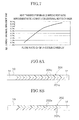
FIG. 1A is a plain view that illustrates atube 1 for a heat exchanger of anembodiment 1. -
FIG. 1B is a longitudinal cross sectional diagram that illustrates a state in which thetube 1 for the heat exchanger of theembodiment 1 is cut along a part not formed with groove shapedconcave parts 1e. -
FIG. 1C is a longitudinal cross sectional diagram that illustrates a state in which thetube 1 for the heat exchanger of theembodiment 1 is cut along a part formed with groove shapedconcave parts 1e. -
FIG. 2 is a perspective view that illustrates a heat exchanger A including thetube 1 of theembodiment 1. -
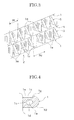
FIG. 3 is a perspective view that illustrates a chief part of the heat exchanger A including thetube 1 of theembodiment 1. -
FIG. 4 is an enlarged longitudinal cross sectional diagram that illustrates a chief part of thetube 1 of theembodiment 1. -
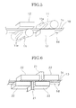
FIG. 5 is a descriptive diagram of a roll processing when manufacturing thetube 1 for the heat exchanger of theembodiment 1. -
FIG. 6 is a descriptive diagram of a press processing when manufacturing thetube 1 for the heat exchanger of theembodiment 1. -
FIG. 7 is a property comparison diagram that illustrates against a conventional heat exchanger, an improvement ratio of a heat transfer efficiency of the heat exchanger A in which thetube 1 of theembodiment 1 is used. -
FIG. 8A is a plain view that illustrates atube 201 for a heat exchanger of anembodiment 2. -
FIG. 8B is a plain view that illustrates atube 202 for a heat exchanger of theembodiment 2. -
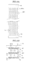
FIG. 9A is a plain view that illustrates atube 301 for a heat exchanger of anembodiment 3. -
FIG. 9B is a cross-sectional diagram that illustrates thetube 301 for the heat exchanger of theembodiment 3. -
FIG. 10A is a plain view that illustrates atube 301 for a heat exchanger of anembodiment 4. -
FIG. 10B is a cross-sectional diagram that illustrates thetube 301 for the heat exchanger of theembodiment 4. -
FIG. 11A is a plain view that illustrates atube 301 for a heat exchanger of anembodiment 5. -
FIG. 11B is a cross-sectional diagram that illustrates thetube 301 for the heat exchanger of theembodiment 5. - 1 tube for a heat exchanger
1a fluid path
1b convex part
1c upper surface part of the tube
1d lower surface part of the tube
1e groove shaped concave part
1f non-forming area
1g non-forming area
5 fin
5a wave peak
10 tube main body
201 tube for a heat exchanger
201e groove shaped concave part
202 tube for a heat exchanger
202e groove shaped concave part
301 tube for a heat exchanger
301e dimple
401 tube for a heat exchanger
401e groove shaped concave part
501 tube for a heat exchanger
501e groove shaped concave part
A heat exchanger - An embodiment of the present invention is described based on the accompanying drawings hereinbelow. A tube for a heat exchanger according to the present invention includes a tube
main body 10 formed by extrusion molding with a plurality offluid paths 1a through each of which a fluid for a heat exchanger flows internally along an extrusion direction and formed to have a long plate shape in the extrusion direction. The tube also includes a plurality of concave parts formed with intervals in the extrusion direction in at least either an upper surface part of the tube or a lower surface part of the tube. The concave parts are obtained by pressing at least either an upper surface part of the tube or a lower surface part of the tube. The upper surface part of the tube is a surface of one side of a thickness direction of the tube main body. The lower surface part of the tube is a surface of a reverse direction to the upper surface part. The pressing is applied in a direction so that a plurality of convex parts can be formed by the pressed concave parts in the fluid paths. The convex parts are projected in a direction that narrows the cross sectional area of the fluid paths. - A heat exchanger A of an
embodiment 1, that is, a best embodiment of the present invention is described hereinbelow based onFIG. 1A through FIG. 7 in which atube 1 is used. - As illustrated in
FIG. 2 , a constitution is adopted in which the left and the right of acore part 2 of the heat exchanger A are supported byheader tanks header tanks core part 2, a plurality oftubes 1 for the heat exchanger and a plurality of fins are layered alternatively. A top and a bottom of the layered structure are put between a pair ofplates - The
tube 1 for the heat exchanger includes a tubemain body 10 of a long plate shape that performs heat transfer with outside air by flowing a fluid for heat exchange internally. For example, metals of aluminum and copper or the like with high heat transfer efficiency are extrusion molded for the tubemain body 10. The tubemain body 10 is formed to have a rectangular plate shape when viewed from above as illustrated inFIG. 1A . In addition, a plurality offluid paths 1a (refer toFIG. 1B ) is formed internally along a whole length of the extrusion direction (LL direction in the figure) with a circular cross section through which the fluid flows. - Heat transfer to the outside air by the
tube 1 for the heat exchanger is helped by afin 5. For example, thefin 5 is formed from metals with a high heat transfer efficiency of aluminum and copper or the like to have a thin plate shape and a wave shape as illustrated inFIG. 3 . - Furthermore, in the
embodiment 1, as illustrated inFIG. 1C , a plurality ofconvex parts 1b are formed with intervals in the extrusion direction of thefluid paths 1a of the tube for the heat exchanger. The plurality of convex parts project internally to narrow a cross-sectional area of the fluid paths. - After the tube
main body 10 is extrusion-molded, by a roll molding or a press molding, anupper surface part 1c of the tube and alower surface part 1d of the tube are pressed to be deformed by their plasticity so that theconvex parts 1b can be formed. Theupper surface part 1c of the tube is a surface of one side of the thickness direction of the tubemain body 10. Thelower surface part 1d of the tube is a surface of a reverse direction to theupper surface part 1c. As illustrated inFIG. 1A , a plurality of groove shapedconcave parts 1e is shaped in the pressed points. As illustrated inFIG. 1C , in parts formed with the groove shapedconcave parts 1e, eachfluid path 1a is pressed in a thickness direction of the tube as a result. Therefore, theconvex parts 1b narrowing the cross sectional area of the fluid path are formed by the pressedconcave parts 1e. - In the case of the roll molding, as illustrated in
FIG. 5 as one example, the tubemain body 10 is put between a pair ofrollers 11 for molding use and a supportingbase 12. In order to be molded, theroller 11 for molding use is moved by rolling along either theupper surface part 1c of the tube or thelower surface part 1d of the tube and the supportingbase 12 is moved along a surface of a reverse side to either theupper surface part 1c or thelower surface part 1d. In addition,convex streaks 11e for shaping the groove shapedconcave parts 1e are formed on an external circumference surface of theroller 11. - In addition, in the case of press molding, as illustrated in
FIG. 6 as one example, in order to be molded, either theupper surface part 1c of thetube 10 or thelower surface part 1d of thetube 10 is pressed by apress mold 21 and a surface of a reverse side to either theupper surface part 1c or thelower surface part 1d is supported by a supportingbase 22. In addition, a pair of the supportingbases press mold 21 is put between. The pair of the supportingbases press mold 21. - The groove shaped
concave parts 1e shaped as described above are formed with an angle θ (θ < 90) against the extrusion direction (a direction of an arrow LL) of thetube 1 for the heat exchanger, that is, to extend obliquely against a width direction (a direction of an arrow RR) which is orthogonal to the extrusion direction and with a constant pitch Pd as illustrated inFIG. 1A . Furthermore, with regard to the groove shapedconcave parts 1e, those formed on a side of theupper surface part 1c of the tubemain body 10 of thetube 1 for the heat exchanger (illustrated by solid lines in the figure) and those formed on a side of thelower surface part 1d of the tube (illustrated by dotted lines in the figure) are formed alternately in the extrusion direction. - In addition, the pitch Pd of the groove shaped
concave part 1e is set to be wider than a pitch Pf of awave peak 5a which is a part of a wave shaped mountain of thefin 5 as illustrated inFIG. 3 . In addition, a length (refer toFIG. 1A ) of one groove shapedconcave part 1e in the extrusion direction (the direction of the arrow LL) is set to have a longer dimension than the pitch Pf of thewave peak 5a of thefins 5. - Furthermore, in the
present embodiment 1, the groove shapedconcave parts 1e are not formed across an entire area in the extrusion direction (the direction of the arrow LL) of the tubemain body 10 of thetube 1 for the heat exchanger.Non-forming areas concave parts 1e are not formed. In both ends of the extrusion direction of the tubemain body 10 of thetube 1 for the heat exchanger, thenon-forming area 1f is set to have a longer dimension L than the parts to be inserted into theheader tanks - In addition, in the width direction (the direction of the arrow RR) of the
tube 1 for the heat exchanger, the groove shapedconcave parts 1e are not formed across a whole width of the tube main body.Non-forming areas main body 10 in which the groove shapedconcave parts 1e are not formed. That is, as illustrated inFIG. 4 , an outermostfluid path 1a disposed in the width direction of the tubemain body 10 of thetube 1 for the heat exchanger has a position. The groove shapedconcave parts 1e are only formed to the position. Further outward areas are defined as thenon-forming area 1g. - Next, operations of the
embodiment 1 are described. In the case thetube 1 for the heat exchanger of theembodiment 1 is formed, first, the tubemain body 10 is formed. The tubemain body 10 is formed internally with a plurality ofliquid paths 1a by extrusion molding. Thereafter, by the pressing according to the roll molding illustrated inFIG. 5 or by the pressing according to the press molding illustrated inFIG. 6 , groove shapedconcave parts 1e are formed in a constant pitch Pd in theupper surface part 1c of the tube and thelower surface part 1d of the tube so that when these groove shapedconcave parts 1e are formed,convex parts 1b are formed in theliquid path 1a of at the pressed parts. - The
tube 1 for the heat exchanger manufactured as such is then layered alternately with thefin 5. The top and the bottom of the laminated body are put between a pair ofplates core part 2. Both ends of thecore part 2 are inserted into theheader tanks - In the
tube 1 for the heat exchanger of theembodiment 1 formed as such, disturbances are generated by the convex parts to a fluid flowing through the liquid paths so that contacts by the fluid to an external circumference surface of the fluid paths are facilitated and heat transfer efficiency is heightened. -
FIG. 7 is a property comparison diagram that illustrates an improvement ratio of heat transfer efficiency of the heat exchanger A in which thetube 1 of theembodiment 1 is used vis-à-vis a conventional heat exchanger in which the tube without theconvex part 1b is used. The diagram illustrates that the higher a flow rate Gr of the fluid (cooling medium), the higher is the improvement ratio of heat transfer capabilities. - In addition, in the forming of the
tube 1 for the heat exchanger of theembodiment 1, after the tube is formed by extrusion molding,convex parts 1b are formed in theliquid paths 1a by pressings of roll molding or press molding. Therefore, thetube 1 for the heat exchanger can be manufactured by simple processings and manufacturing costs can be suppressed. - Furthermore, in the
tube 1 for the heat exchanger of theembodiment 1, the groove shapedconcave parts 1e are extended obliquely against the width direction of thetube 1 for the heat exchanger so that an excellent contact property with thefin 5 is obtained. That is, in the case the groove shapedconcave parts 1e are formed in the width direction, there is possibility that the groove shapedconcave parts 1e doubles thewave peak 5a of thefin 5 in disposition. In that case, thewave peak 5a is not in contact with theupper surface part 1c of the tube or thelower surface part 1d of the tube across an approximate whole length of the width direction so that heat transfer efficiency of this part is worsened. In comparison, in thepresent embodiment 1, the groove shapedconcave parts 1e are formed obliquely against the width direction. Therefore, there is no possibility that thewave peak 5a of thefin 5 maintains a non-contact state across its approximate whole length in the way just described. Consequently, worsening of heat transfer efficiency can be suppressed. - In addition, in the case the groove shaped
concave parts 1e are extended obliquely in such a way, a part of thewave peak 5a of thefin 5 intersecting and doubling the groove shaped concave part is not in contact with theupper surface part 1c of the tube or thelower surface part 1d of the tube. But an area of the part is small and a periphery of the part is necessarily in contact with these upper andlower surface parts wave peak 5a is not in contact across its approximate whole length. In addition, in theembodiment 1, the pitch Pd of the groove shapedconcave part 1e is set to be larger than the pitch Pf of thewave peak 5a of thefin 5. Therefore, in comparison to a case in which Pd < Pf, occurrences of non-contact areas, that is, intersection areas between the groove shapedconcave parts 1e and thewave peak 5a of thefin 5 can be suppressed so that heat transfer efficiency can be heightened. - Furthermore, in the
present embodiment 1, a length x in the extrusion direction of the concave shapedgroove parts 1e is set to be wider than the pitch Pf of thewave peak 5a of thefin 5 so that a plurality of peaks are doubled to one groove shapedconcave part 1e. In such a way, thewave peak 5a gets into the groove shapedconcave part 1e and a rolled over state of thefin 5 can be prevented. Also in such a way, a good state of contact between thefin 5 and thetube 1 for the heat exchanger can be secured and heat transfer efficiency can be heightened. - In addition, in the
embodiment 1,non-forming areas tube 1 for the heat exchanger in which the groove shapedconcave parts 1e are not formed. Therefore, in the case both ends of thetube 1 for the exchanger are inserted intoheader tanks concave parts 1e exist in the inserted part, seal properties can be easily secured. - In addition, in the
embodiment 1, groove shaped concave parts in theupper surface part 1c of thetube 1 for the heat exchanger and thelower surface part 1d of thetube 1 are formed alternately. Therefore, in comparison to a case in which the groove shapedconcave parts 1e of bothsurfaces tube 1 for the heat exchanger in the thickness direction of the tube at the position of the groove shapedconcave parts 1e can be suppressed. In addition,non-forming areas tube 1 for the heat exchanger. An outermostfluid path 1a disposed in the width direction of the tube has a position. The groove shapedconcave parts 1e are only formed to the position. Therefore, in comparison to a case in which the groove shaped concave parts are formed across a whole width of thetube 1 for the heat exchanger, bend overs of thetube 1 for the heat exchanger in the thickness direction of the tube at the position of the groove shapedconcave parts 1e can be suppressed. - Next, based on
FIG. 8A and FIG. 8B , atube 201 and atube 202 for a heat exchanger of anembodiment 2 of the present invention are described. In addition, theembodiment 2 is a modified example of theembodiment 1. Therefore, only differing points are described. Descriptions of the same constitutions, operations and effects as theembodiment 1 are abbreviated. - In the
embodiment 2, shapes of groove shapedconcave parts tube embodiment 1. That is, the groove shapedconcave parts 201e illustrated inFIG. 8A are formed to have a V letter shape as illustrated hereby. In addition, the groove shapedconcave parts 202e of thetube 202 for the heat exchanger, as illustrated inFIG. 8B , is an example in which two pieces constituting a V letter are formed alternately. In addition, descriptions of operations and effects are the same to theembodiment 1 so that they are abbreviated. - Next, based on
FIG. 9A and FIG. 9B , atube 301 for a heat exchanger of anembodiment 3 of the present invention are described. In addition, theembodiment 3 is a modified example of theembodiment 1. Therefore, only differing points are described. Descriptions of the same constitutions, operations and effects as theembodiment 1 are abbreviated. - The
tube 301 for the heat exchanger of theembodiment 3, as illustrated inFIG. 9A , is an example in which a plurality of lines and a plurality of columns of dimples are formed in anupper surface part 1c of the tube. The dimples are approximately square shaped when viewing concave parts from above. - In the
embodiment 3, thedimples 301e are formed as the concave parts.
Therefore, in comparison to a case in which the groove shaped concave parts are formed across a whole width of a width direction of areas formed with thedimples 301e, contact areas with thefin 5 are secured and heat transfer efficiency can be heightened. In comparison to a case in which the groove shaped concave parts are formed, bend overs of thetube 301 for the heat exchanger can be suppressed. In addition, thewave peak 5a of thefin 5 is fitted into a groove so that a roll over is prevented. - In addition, the
embodiment 3 is also the same to theembodiment 1 in that firstly, heat transfer efficiency can be heightened in comparison to a case in which theconvex parts 1b are not formed; secondly, manufacturing costs can be suppressed due to simple manufacture by extrusion molding, roll molding or press molding and thirdly, seal properties can be easily secured due to thenon-forming area 1f at both end parts of the extrusion direction. - Next, based on
FIG. 10A and FIG. 10B , atube 401 for a heat exchanger of anembodiment 4 of the present invention are described. In addition, theembodiment 4 is a modified example of theembodiment 1. Therefore, only differing points are described. Descriptions of the same constitutions, operations and effects as theembodiment 1 are abbreviated. - the
tube 401 for the heat exchanger of theembodiment 4, as illustrated inFIG. 10 , is an example in which groove shapedconcave parts 401e are formed in the width direction in theupper surface part 1c of the tube and thelower surface part 1d of the tube so thatconvex parts 1b are formed by the pressedconcave parts 401 e. In addition, a pitch Pd of the groove shapedconcave parts 401e is shaped to be larger than a pitch Pf of thewave peak 5a of thefin 5. In addition, thenon-forming area 1g is formed in both end parts of the width direction. - In addition, the
embodiment 4 is also the same to theembodiment 1 in that firstly, heat transfer efficiency can be heightened in comparison to a case in which theconvex parts 1b are not formed; secondly, manufacturing costs can be suppressed due to simple manufacture by extrusion molding, roll molding or press molding, thirdly, seal properties can be easily secured due to thenon-forming area 1f at both end parts of the extrusion direction and fourthly, thetube 401 becomes difficult to be bent over because groove shapedconcave parts 401e are formed alternately in the upper andlower surface parts non-forming area 1g is set. - Next, based on
FIG. 11A and FIG. 11B , atube 501 for a heat exchanger of anembodiment 5 of the present invention are described. In addition, theembodiment 5 is a modified example of theembodiment 1. Therefore, only differing points are described. Descriptions of the same constitutions, operations and effects as theembodiment 1 are abbreviated. - the
tube 501 for the heat exchanger of theembodiment 5, as illustrated inFIG. 11A , is an example in which groove shapedconcave parts 501e are formed in the width direction across a whole width of theupper surface part 1c of the tube and thelower surface part 1d of the tube so thatconvex parts 1b are formed by the pressedconcave parts 501e. In addition, a pitch Pd of the groove shapedconcave parts 1e is shaped to be larger than a pitch Pf of thewave peak 5a of thefin 5. In addition, thenon-forming area 1g is formed in both end parts of the width direction. - In addition, the
embodiment 5 is also the same to theembodiment 1 in that firstly, heat transfer efficiency can be heightened in comparison to a case in which theconvex parts 1b are not formed; secondly, manufacturing costs can be suppressed due to simple manufacture by extrusion molding, roll molding or press molding, thirdly, seal properties can be easily secured due to thenon-forming area 1f at both end parts of the extrusion direction and fourthly, thetube 501 becomes difficult to be bent over because groove shapedconcave parts 501e are formed alternately in the upper andlower surface parts - The
embodiment 1 through 5 of the present invention and the best mode for carrying out the invention are described in detail above with reference to the drawings but the specific constitutions are not limited to theembodiment 1 through 5 and the best mode for carrying out the invention. A degree of changes in design that does not deviate from the scope of the invention is included in the present invention. - For example, in the
embodiment 1 through 5, the shape of thefluid paths 1a is circular in its cross section but shape is not limited to such and thefluid paths 1a can be formed to other shapes such as polygonal shapes of rectangles or the like as well as elliptical shapes. The number of the fluid paths is also not limited to the number illustrated in the embodiments. For example, in the embodiments, thefluid paths 1a are formed into one lateral line but thefluid paths 1a can have a different array with the embodiments in which two lateral lines are formed or the like. - In addition, in the
embodiments 1 through 5, the thin plate shapedfin 5 of a wave form is illustrated as a fin but the shape of the fin is not limited to this. For example, a fin of other shapes such as a flat plate shape or a honeycomb shape or the like can be used. In addition, the fin can differ from a contact type of theembodiment 1 through 5 and a welding type can be used. - In addition, in the
embodiments 1 through 5, an example is illustrated in which the concave parts are formed on both the upper and the lower surface of thetube 1 for the exchanger but the concave parts can be formed only on either the upper surface or the lower surface. - In addition, in the
embodiments 1 through 5, when thetube 1 for the heat exchanger and thefin 5 are layered, an example is illustrated in which thetube 1 for the heat exchanger and thefin 5 are disposed alternately but it is not limited to such. For example, one tube can be put between two fins to form a laminated body and a plurality of the laminated body can then be layered. - In addition, in the case convex parts are formed by the
dimples 301e illustrated in theembodiment 3, a plain surface shape of the dimples are not limited to the rectangle illustrated in theembodiment 3 but the dimples can formed to other shapes of triangle and round or the like. In addition, in this case, projections formed by the dimples have shapes of rectangular spindles, triangular pyramids and circular cones or the like so that the shape of the convex parts can be a shape that projects by point instead of projecting from one side of thefluid path 1a towards the entirefluid path 1a as illustrated in theembodiment 1 through 5. - The present invention is based on and claims priority benefit from Japanese Patent Application No.
2006-283529, filed on October 18, 2006 - In addition, the present invention is not limited to the above embodiments.
It is clear to those skilled in the art that changes can be made without deviating from the claims and the scope thereof.
Claims (15)
- A tube for a heat exchanger, comprising:a tube main body obtained by extrusion molding with a long plate shape in an extrusion direction and formed along the extrusion direction with a plurality of fluid paths through each of which a fluid for the heat exchange flows internally, anda plurality of concave parts formed with intervals in a pressing direction, whereinat least either an upper surface part of the tube which is a surface of one side in a thickness direction of the tube main body or a lower surface part of the tube which is a surface of a reverse direction to the upper surface part is pressed to form the concave parts, andthe concave parts are pressed in the direction to form as a result convex parts in the fluid paths which are projected in a direction that narrows a cross sectional area of each of the fluid path.
- The tube for the heat exchanger according to Claim 1, wherein
the concave parts are formed to have a groove shape and extend obliquely against an orthogonal direction of the extrusion direction of the tube main body. - The tube for the heat exchanger according to Claim 2, wherein
the interval in the extrusion direction of the groove shaped concave part is set to be wider than an interval between wave peaks of wave shaped fins used for lamination. - The tube for the heat exchanger according to Claim 1, further comprising:a non-forming area disposed in both end parts of the extrusion direction of the tube main body in which the concave parts are not formed.
- The tube for the heat exchanger according to Claim 1, wherein
the concave parts are formed on both the upper surface part of the tube and the lower surface part of the tube in which the concave parts formed on the upper surface part of the tube and the concave parts formed on the lower surface part of the tube are disposed to not double in the thickness direction. - The tube for the heat exchanger according to Claim 1, further comprising:a non-forming area disposed in both end parts of the orthogonal direction of the extrusion direction in which the concave parts are not formed.
- A process of manufacturing a tube for a heat exchanger, comprising the steps of:obtaining by extrusion molding a tube main body of the tube for the heat exchanger laminated for usage with a fin for the heat exchanger in which the tube main body is metal made, long plate shaped in an extrusion direction and formed along the extrusion direction with a plurality fluid paths through which a fluid for heat exchange flows internally,pressing at least either an upper surface part of the tube which is a surface of one side in a thickness direction of the tube main body or a lower surface part of the tube which is a surface of a reverse direction to the upper surface part to form a plurality of concave parts with intervals in the extrusion direction in at least either the upper surface part of the tube or the lower surface part of the tube, andforming by the pressed concave parts a plurality of convex parts in the fluid paths with intervals in the extrusion direction and projected in a direction that narrows a cross sectional area of the fluid paths.
- The tube for the heat exchanger according to Claim 7, wherein
the concave parts are formed to have a groove shape and extend obliquely against an orthogonal direction to the extrusion direction of the tube main body. - The tube for the heat exchanger according to Claim 8, wherein
the interval in the extrusion direction of the groove shaped concave part is set to be wider than an interval between wave peaks of wave shaped fins used for lamination. - The tube for the heat exchanger according to Claim 7, further comprising:a non-forming area disposed in both end parts of the extrusion direction of the tube in which the concave part is not formed.
- The tube for the heat exchanger according to Claim 7, wherein
the concave parts are formed on both the upper surface part of the tube and the lower surface part of the tube in which the concave parts formed on the upper surface part of the tube and the concave parts formed on the lower surface part of the tube are disposed to not double in the thickness direction. - The tube for the heat exchanger according to Claim 7, further comprising:a non-forming area disposed in both end parts of the orthogonal direction to the extrusion direction in which the concave part is not formed.
- A manufacturing method of a tube for a heat exchanger, wherein
the tube for the heat exchanger is layered for usage with fins for heat transfer in which a plurality of the fluid paths through which a fluid for heat exchange flows internally is formed along an extrusion direction, comprising the steps of:forming by extrusion molding a tube main body that includes the plurality of fluid paths,pressing at least either an upper surface part of the tube which is a surface of one side in a thickness direction of the tube main body or a lower surface part of the tube which is a surface of a reverse direction to the upper surface part to form a plurality of concave parts with intervals in the extrusion direction, andforming by the pressed concave parts a plurality of convex parts with intervals in the extrusion direction and projected in a direction that narrows a cross sectional area of the fluid paths. - The manufacturing method of the tube for the heat exchanger according to Claim 13, wherein
the concave parts are formed to have a groove shape and extend obliquely against an orthogonal direction of the extrusion direction of the tube main body. - The manufacturing method of the tube for the heat exchanger according to Claim 14, wherein
the interval in the extrusion direction of the groove shaped concave part is set to be wider than an interval between wave peaks of wave shaped fins used for lamination.
Applications Claiming Priority (2)
| Application Number | Priority Date | Filing Date | Title |
|---|---|---|---|
| JP2006283529A JP2008101820A (en) | 2006-10-18 | 2006-10-18 | Tube for heat exchanger and its manufacturing method |
| PCT/JP2007/070239 WO2008047827A1 (en) | 2006-10-18 | 2007-10-17 | Heat exchanger tube and method of producing the same |
Publications (1)
| Publication Number | Publication Date |
|---|---|
| EP2085733A1 true EP2085733A1 (en) | 2009-08-05 |
Family
ID=39314049
Family Applications (1)
| Application Number | Title | Priority Date | Filing Date |
|---|---|---|---|
| EP07829973A Withdrawn EP2085733A1 (en) | 2006-10-18 | 2007-10-17 | Heat exchanger tube and method of producing the same |
Country Status (4)
| Country | Link |
|---|---|
| US (1) | US20100294473A1 (en) |
| EP (1) | EP2085733A1 (en) |
| JP (1) | JP2008101820A (en) |
| WO (1) | WO2008047827A1 (en) |
Cited By (2)
| Publication number | Priority date | Publication date | Assignee | Title |
|---|---|---|---|---|
| CN101995115A (en) * | 2009-08-07 | 2011-03-30 | 江森自控科技公司 | Multi-channel heat exchanger fins |
| WO2020093713A1 (en) * | 2018-11-06 | 2020-05-14 | 深圳市贝腾科技有限公司 | Heat exchange device and freeze dryer |
Families Citing this family (4)
| Publication number | Priority date | Publication date | Assignee | Title |
|---|---|---|---|---|
| JP2010085046A (en) * | 2008-10-01 | 2010-04-15 | Mitsubishi Alum Co Ltd | Tube for heat exchanger, manufacturing method therefor, and heat exchanger |
| JP5694282B2 (en) * | 2012-12-10 | 2015-04-01 | 株式会社小松製作所 | Corrugated fin and heat exchanger provided with the same |
| WO2017066717A2 (en) * | 2015-10-14 | 2017-04-20 | Mark Miles | Induced convection heat exchanger |
| US10921066B2 (en) * | 2018-06-25 | 2021-02-16 | Getac Technology Corporation | Enhanced heat dissipation module, cooling fin structure and stamping method thereof |
Family Cites Families (4)
| Publication number | Priority date | Publication date | Assignee | Title |
|---|---|---|---|---|
| JPS6391492A (en) * | 1986-10-03 | 1988-04-22 | Nippon Denso Co Ltd | Heat exchanger |
| JPH08285485A (en) * | 1995-04-11 | 1996-11-01 | Toyota Autom Loom Works Ltd | Car radiator tube |
| JPH1019492A (en) * | 1996-07-03 | 1998-01-23 | Zexel Corp | Flat tubes for heat exchangers |
| JP2000193387A (en) | 1998-12-25 | 2000-07-14 | Showa Alum Corp | Flat heat exchange tube and method for producing the same |
-
2006
- 2006-10-18 JP JP2006283529A patent/JP2008101820A/en not_active Withdrawn
-
2007
- 2007-10-17 US US12/311,863 patent/US20100294473A1/en not_active Abandoned
- 2007-10-17 EP EP07829973A patent/EP2085733A1/en not_active Withdrawn
- 2007-10-17 WO PCT/JP2007/070239 patent/WO2008047827A1/en not_active Ceased
Non-Patent Citations (1)
| Title |
|---|
| See references of WO2008047827A1 * |
Cited By (3)
| Publication number | Priority date | Publication date | Assignee | Title |
|---|---|---|---|---|
| CN101995115A (en) * | 2009-08-07 | 2011-03-30 | 江森自控科技公司 | Multi-channel heat exchanger fins |
| WO2020093713A1 (en) * | 2018-11-06 | 2020-05-14 | 深圳市贝腾科技有限公司 | Heat exchange device and freeze dryer |
| US11633694B2 (en) | 2018-11-06 | 2023-04-25 | Shenzhen Biteman Technology Co., Ltd. | Heat exchange device and freeze dryer |
Also Published As
| Publication number | Publication date |
|---|---|
| US20100294473A1 (en) | 2010-11-25 |
| JP2008101820A (en) | 2008-05-01 |
| WO2008047827A1 (en) | 2008-04-24 |
Similar Documents
| Publication | Publication Date | Title |
|---|---|---|
| CN1057157C (en) | Pipe for flowing of refrigerant in heat exchanger | |
| US6213158B1 (en) | Flat turbulator for a tube and method of making same | |
| US7182128B2 (en) | Heat exchanger tube having strengthening deformations | |
| CN108139179A (en) | Fins for plate heat exchangers and manufacturing method thereof | |
| US20100294473A1 (en) | Tube for heat exchanger and method for manufacturing the same | |
| JP2009063228A (en) | Flat heat transfer tube | |
| US6594897B2 (en) | Method for manufacturing coolant tube of heat exchanger | |
| US10267573B2 (en) | Polyhedral array heat transfer tube | |
| US7059394B2 (en) | Heat exchanger | |
| US20050067156A1 (en) | Pressure containing heat transfer tube and method of making thereof | |
| CN109604367B (en) | Roll bending forming device and method for variable-thickness folding type micro-channel flat tube | |
| JP3870865B2 (en) | Heat exchanger | |
| CN102052866A (en) | Finned tube type heat exchanger and manufacturing method thereof | |
| US20020074109A1 (en) | Turbulator with offset louvers and method of making same | |
| JPH03251688A (en) | Manufacture of tube member for heat exchanger | |
| EP1106949A1 (en) | Folded tube for a heat exchanger and method of making same | |
| JP2007017132A (en) | Heat exchange tubes and heat exchangers | |
| US20070062682A1 (en) | Multiple-hole tube for heat exchanger and manufacturing method thereof | |
| CN212058426U (en) | Heat exchanger | |
| JP2009250600A (en) | Copper flat heat-transfer pipe | |
| CN106949768A (en) | Multi-channel hot exchanges flat tube | |
| JP3752046B2 (en) | Heat transfer tube and manufacturing method thereof | |
| JPH0284253A (en) | Heat exchanger tube and its manufacturing method | |
| KR20080089972A (en) | Heat exchanger of air conditioner and manufacturing method thereof | |
| JP3779794B2 (en) | Internal grooved heat transfer tube and manufacturing method thereof |
Legal Events
| Date | Code | Title | Description |
|---|---|---|---|
| PUAI | Public reference made under article 153(3) epc to a published international application that has entered the european phase |
Free format text: ORIGINAL CODE: 0009012 |
|
| 17P | Request for examination filed |
Effective date: 20090416 |
|
| AK | Designated contracting states |
Kind code of ref document: A1 Designated state(s): AT BE BG CH CY CZ DE DK EE ES FI FR GB GR HU IE IS IT LI LT LU LV MC MT NL PL PT RO SE SI SK TR |
|
| DAX | Request for extension of the european patent (deleted) | ||
| STAA | Information on the status of an ep patent application or granted ep patent |
Free format text: STATUS: THE APPLICATION HAS BEEN WITHDRAWN |
|
| 18W | Application withdrawn |
Effective date: 20100929 |