EP2085680A1 - Led lighting module - Google Patents
Led lighting module Download PDFInfo
- Publication number
- EP2085680A1 EP2085680A1 EP09151044A EP09151044A EP2085680A1 EP 2085680 A1 EP2085680 A1 EP 2085680A1 EP 09151044 A EP09151044 A EP 09151044A EP 09151044 A EP09151044 A EP 09151044A EP 2085680 A1 EP2085680 A1 EP 2085680A1
- Authority
- EP
- European Patent Office
- Prior art keywords
- lighting module
- optical assembly
- holder
- leds
- optical
- Prior art date
- Legal status (The legal status is an assumption and is not a legal conclusion. Google has not performed a legal analysis and makes no representation as to the accuracy of the status listed.)
- Granted
Links
- 230000003287 optical effect Effects 0.000 claims abstract description 49
- 239000011159 matrix material Substances 0.000 claims abstract description 7
- 230000000717 retained effect Effects 0.000 claims abstract description 4
- 239000003086 colorant Substances 0.000 claims description 6
- 230000002093 peripheral effect Effects 0.000 claims 1
- 239000012780 transparent material Substances 0.000 claims 1
- 239000000463 material Substances 0.000 description 2
- 229920003229 poly(methyl methacrylate) Polymers 0.000 description 2
- 239000004926 polymethyl methacrylate Substances 0.000 description 2
- CERQOIWHTDAKMF-UHFFFAOYSA-M Methacrylate Chemical compound CC(=C)C([O-])=O CERQOIWHTDAKMF-UHFFFAOYSA-M 0.000 description 1
- 238000004026 adhesive bonding Methods 0.000 description 1
- 230000003321 amplification Effects 0.000 description 1
- 238000003491 array Methods 0.000 description 1
- 239000002131 composite material Substances 0.000 description 1
- 238000001816 cooling Methods 0.000 description 1
- 230000008878 coupling Effects 0.000 description 1
- 238000010168 coupling process Methods 0.000 description 1
- 238000005859 coupling reaction Methods 0.000 description 1
- 230000007423 decrease Effects 0.000 description 1
- 230000001419 dependent effect Effects 0.000 description 1
- 230000004907 flux Effects 0.000 description 1
- 238000001746 injection moulding Methods 0.000 description 1
- 230000004048 modification Effects 0.000 description 1
- 238000012986 modification Methods 0.000 description 1
- 238000003199 nucleic acid amplification method Methods 0.000 description 1
- 229920003023 plastic Polymers 0.000 description 1
- 238000005476 soldering Methods 0.000 description 1
- 239000000243 solution Substances 0.000 description 1
Images


Classifications
-
- G—PHYSICS
- G02—OPTICS
- G02B—OPTICAL ELEMENTS, SYSTEMS OR APPARATUS
- G02B7/00—Mountings, adjusting means, or light-tight connections, for optical elements
- G02B7/02—Mountings, adjusting means, or light-tight connections, for optical elements for lenses
- G02B7/022—Mountings, adjusting means, or light-tight connections, for optical elements for lenses lens and mount having complementary engagement means, e.g. screw/thread
-
- F—MECHANICAL ENGINEERING; LIGHTING; HEATING; WEAPONS; BLASTING
- F21—LIGHTING
- F21K—NON-ELECTRIC LIGHT SOURCES USING LUMINESCENCE; LIGHT SOURCES USING ELECTROCHEMILUMINESCENCE; LIGHT SOURCES USING CHARGES OF COMBUSTIBLE MATERIAL; LIGHT SOURCES USING SEMICONDUCTOR DEVICES AS LIGHT-GENERATING ELEMENTS; LIGHT SOURCES NOT OTHERWISE PROVIDED FOR
- F21K9/00—Light sources using semiconductor devices as light-generating elements, e.g. using light-emitting diodes [LED] or lasers
- F21K9/60—Optical arrangements integrated in the light source, e.g. for improving the colour rendering index or the light extraction
- F21K9/69—Details of refractors forming part of the light source
-
- F—MECHANICAL ENGINEERING; LIGHTING; HEATING; WEAPONS; BLASTING
- F21—LIGHTING
- F21V—FUNCTIONAL FEATURES OR DETAILS OF LIGHTING DEVICES OR SYSTEMS THEREOF; STRUCTURAL COMBINATIONS OF LIGHTING DEVICES WITH OTHER ARTICLES, NOT OTHERWISE PROVIDED FOR
- F21V17/00—Fastening of component parts of lighting devices, e.g. shades, globes, refractors, reflectors, filters, screens, grids or protective cages
- F21V17/10—Fastening of component parts of lighting devices, e.g. shades, globes, refractors, reflectors, filters, screens, grids or protective cages characterised by specific fastening means or way of fastening
- F21V17/16—Fastening of component parts of lighting devices, e.g. shades, globes, refractors, reflectors, filters, screens, grids or protective cages characterised by specific fastening means or way of fastening by deformation of parts; Snap action mounting
- F21V17/164—Fastening of component parts of lighting devices, e.g. shades, globes, refractors, reflectors, filters, screens, grids or protective cages characterised by specific fastening means or way of fastening by deformation of parts; Snap action mounting the parts being subjected to bending, e.g. snap joints
-
- F—MECHANICAL ENGINEERING; LIGHTING; HEATING; WEAPONS; BLASTING
- F21—LIGHTING
- F21V—FUNCTIONAL FEATURES OR DETAILS OF LIGHTING DEVICES OR SYSTEMS THEREOF; STRUCTURAL COMBINATIONS OF LIGHTING DEVICES WITH OTHER ARTICLES, NOT OTHERWISE PROVIDED FOR
- F21V5/00—Refractors for light sources
- F21V5/007—Array of lenses or refractors for a cluster of light sources, e.g. for arrangement of multiple light sources in one plane
-
- F—MECHANICAL ENGINEERING; LIGHTING; HEATING; WEAPONS; BLASTING
- F21—LIGHTING
- F21V—FUNCTIONAL FEATURES OR DETAILS OF LIGHTING DEVICES OR SYSTEMS THEREOF; STRUCTURAL COMBINATIONS OF LIGHTING DEVICES WITH OTHER ARTICLES, NOT OTHERWISE PROVIDED FOR
- F21V7/00—Reflectors for light sources
- F21V7/0091—Reflectors for light sources using total internal reflection
-
- F—MECHANICAL ENGINEERING; LIGHTING; HEATING; WEAPONS; BLASTING
- F21—LIGHTING
- F21V—FUNCTIONAL FEATURES OR DETAILS OF LIGHTING DEVICES OR SYSTEMS THEREOF; STRUCTURAL COMBINATIONS OF LIGHTING DEVICES WITH OTHER ARTICLES, NOT OTHERWISE PROVIDED FOR
- F21V13/00—Producing particular characteristics or distribution of the light emitted by means of a combination of elements specified in two or more of main groups F21V1/00 - F21V11/00
- F21V13/02—Combinations of only two kinds of elements
- F21V13/04—Combinations of only two kinds of elements the elements being reflectors and refractors
Definitions
- the present invention refers to an LED lighting module.
- LED lighting modules are widely used in the interior lighting field, and in the wall lighting field in particular.
- An LED lighting module generally comprises an LED coupled with an optical assembly consisting of a lens able to amplify the brightness of the LED.
- paraboloid-in-shape lenses are generally used, in which the LED is placed in the paraboloid focus.
- lighting modules comprising a lens with a hexagonal perimeter are known to the art. In this manner it is possible to compose a honeycomb lighting system, reducing the empty spaces, but the problem remains of having to assemble each LED individually, together with the difficulty in obtaining a mixing of the light beams of the various LEDs.
- Object of the present invention is to overcome the drawbacks of the prior art by providing an LED lighting module that is versatile, practical, cheap and simple to produce.
- Another object of the present invention is to provide such a lighting module that has a high luminosity and is able to mix the light emitted in order to light walls.
- the lighting module according to the invention comprises:
- a lighting module having a square perimeter, consisting of a square matrix of four LEDs is obtained.
- the main advantage of these lighting modules is represented by the fact that they can be placed side by side in order to obtain a homogeneous lighting surface.
- a matrix with a square or a rectangular area of the desired size can be composed, for example a matrix of m x n modules, or the modules can be disposed linearly, for example composing an array of 1 x n modules.
- LEDs of different colours i.e. emitting light of different colour
- the same result can be obtained with the single-LED lighting modules of the prior art, placed side by side, but with a great assembly difficulty and a little possibility of varying the colours.
- the colour of the LEDs can be varied on a double row.
- the colour of the LEDs can be varied on a double row.
- the lighting module according to the invention designated as a whole with the reference numeral 1, is described with the aid of the figures.
- the lighting module 1 comprises a printed circuit board (PCB) 2 on which four LEDs 3 are mounted, a holder 4 adapted to be disposed on the board 2 and an optical assembly 5 adapted to be retained by the holder 4.
- PCB printed circuit board
- the printed circuit board 2 is substantially square or rectangular in shape, and the four LEDs 3 are disposed on the board 2 to form a matrix of two rows and two columns.
- the LEDs 3 are preferably arranged according to the corners of a square. Furthermore, the LEDs 3 are arranged at a short distance from each other, for example at a distance smaller than 1 cm, so as to minimise the overall dimensions of the module 1.
- Each LED 3 is preferably a high-efficiency one and has an electrical power of about 1.2 W and a luminous flux of 100-400 Lumens.
- the LEDs 3 can preferably emit light of different colours, for example Red, Green, Blue and White. With the combination of these four basic colours a vast range of composite colours can be obtained.
- the holder 4 comprises a square base plate 40 around which a square frame 41 is disposed.
- Four tapered seats 42 with a diameter that decreases as the distance from the base plate 40 increases are formed in the base plate 40.
- Each seat 42 is open at its ends and defines a paraboloid-in-shape cavity 43.
- the base plate 40 At the corners of the base plate 40 are disposed four legs 44 of a length slightly greater than the length of the seats 42, so as to rest on the printed circuit board 2 maintaining the bottom edge of the seats 42 in contact with the LEDs 3.
- the legs 44 can be fixed to the printed circuit board 2 in any known manner, such as for example by click-in coupling, by soldering, by gluing or by means of other fixing systems.
- a through hole 45 is formed near the mid-point of one side edge of the base plate 40 of the holder 4.
- the optical assembly 5 comprises a square base plate 50, adapted to be disposed on the base plate 40 of the holder 4, contained by the frame 41 of the holder 4.
- Four paraboloid-in-shape lenses 52 adapted to be inserted into the respective cavities 43 formed in the seats 42 of the holder 4, are connected to the base plate 50 of the optical assembly 5.
- a cylindrical centring pin 55 adapted to be inserted in the centring hole 45 of the base plate 40 of the holder 4 is connected to the base plate 50 of the optical assembly 5.
- each paraboloid-in-shape lens 52 has on its axis a first blind hole 56, open on the base plate 50 and a second blind hole 57 open at the bottom edge of the lens 52.
- the first blind hole 56 is substantially cylindrical or frustoconical in shape and the second blind hole 57 is substantially paraboloid in shape and is adapted to receive the emitting part of the LED 3.
- Cooling slots 58 arranged cross-wise between the blind holes 56 are formed on the base plate 50 of the optical assembly 5.
- the slots 58 pass through the whole optical assembly 5 between the lenses 52 and communicate with respective gaps 48 between the lenses 52 and the seats 42 of the holder 4 wherein said lens 52 are inserted. In this manner, the hot air on the circuit board 2 is conveyed outside through said gaps 48 and said slots 58.
- the optical assembly 5 is produced in a single piece by injection moulding of a suitable transparent plastic material, such as, for example, methacrylate or PMMA (polymethylmethacrylate).
- a suitable transparent plastic material such as, for example, methacrylate or PMMA (polymethylmethacrylate).
- the lighting module 1 can include one or more optical converters 6 which serve to vary the optical aperture of the light beam leaving the optical assembly 5.
- the optical converter 6 is in the form of a sheet that is disposed inside the frame 41 of the holder 4, above the flat base plate 50 of the optical assembly 5.
- the optical converter 6 is snap fastened into the frame 41.
- the optical converter 6 has two ribs 66 which protrude from two opposite side edges thereof.
- the ribs 66 of the optical converter 6 engage in respective apertures 146 formed in two opposite sides of the frame 41 of the holder 4.
- the optical assembly 5 also can have, in the opposite side edges of its flat base plate 50, ribs 155 which, in figure 4 , are snap engage in respective apertures 145 formed in the other two opposite sides of the square frame 41 of the holder 4.
- the optical converter 6 can have a textured surface, according to the type of aperture of the light beam required.
- the surface of the optical converter is left smooth.
- the upper surface of the optical converter 6 is textured with more or less marked knurling, undulations or grooves according to the desired beam aperture.
- the textured surface of the optical converter 6 is made to face towards the flat base plate 50 of the optical assembly 5.
- the optical converter 6 is made of the same material as the optical assembly 5 and has a thickness of about 1-1.8 mm, depending upon the surface texturing.
Landscapes
- Engineering & Computer Science (AREA)
- General Engineering & Computer Science (AREA)
- Physics & Mathematics (AREA)
- Optics & Photonics (AREA)
- Microelectronics & Electronic Packaging (AREA)
- General Physics & Mathematics (AREA)
- Non-Portable Lighting Devices Or Systems Thereof (AREA)
- Fastening Of Light Sources Or Lamp Holders (AREA)
- Led Devices (AREA)
- Securing Globes, Refractors, Reflectors Or The Like (AREA)
Abstract
Description
- The present invention refers to an LED lighting module.
- LED lighting modules are widely used in the interior lighting field, and in the wall lighting field in particular. An LED lighting module generally comprises an LED coupled with an optical assembly consisting of a lens able to amplify the brightness of the LED.
- In order to maximise the amplification of the lens, paraboloid-in-shape lenses are generally used, in which the LED is placed in the paraboloid focus.
- However, such types of lighting modules comprising a single LED hold some drawbacks. In fact, when a lighting system is to be composed, it is necessary to put together a plurality of lighting modules. Since the perimeter of each lighting module is circular, it is difficult to position the lighting modules correctly. In fact, even if the modules are disposed touching each other, empty gaps still remain and the luminosity of the individual modules it not best exploited.
- To overcome these drawbacks at least in part, lighting modules comprising a lens with a hexagonal perimeter are known to the art. In this manner it is possible to compose a honeycomb lighting system, reducing the empty spaces, but the problem remains of having to assemble each LED individually, together with the difficulty in obtaining a mixing of the light beams of the various LEDs.
- Object of the present invention is to overcome the drawbacks of the prior art by providing an LED lighting module that is versatile, practical, cheap and simple to produce.
- Another object of the present invention is to provide such a lighting module that has a high luminosity and is able to mix the light emitted in order to light walls.
- These objects are achieved in accordance with the invention with the characteristics listed in appended
independent claim 1. - Advantageous embodiments of the invention are apparent from the dependent claims.
- The lighting module according to the invention comprises:
- four LEDs mounted, according to a square matrix, on an essentially square printed circuit board,
- a holder disposed on said printed circuit board and provided with a square frame, and
- an optical assembly retained by said holder and provided with four paraboloid-in-shape lenses coupled to said four LEDs.
- In this manner a lighting module having a square perimeter, consisting of a square matrix of four LEDs, is obtained. The main advantage of these lighting modules is represented by the fact that they can be placed side by side in order to obtain a homogeneous lighting surface. With these modules a matrix with a square or a rectangular area of the desired size can be composed, for example a matrix of m x n modules, or the modules can be disposed linearly, for example composing an array of 1 x n modules.
- It must be considered that with the round lighting modules of the prior art, it is impossible to obtain these types of matrices and of arrays, even if the modules are placed touching each other.
- In the module according to the invention, LEDs of different colours, i.e. emitting light of different colour, can advantageously be used to mix the light beams leaving the module. The same result can be obtained with the single-LED lighting modules of the prior art, placed side by side, but with a great assembly difficulty and a little possibility of varying the colours.
- Furthermore, it must be considered that with the square, four-LED lighting module according to the invention, the colour of the LEDs can be varied on a double row. Thus is it possible to obtain types of light mixing between the two rows too.
- Further characteristics of the invention will be made clearer by the detailed description that follows, referring to a purely exemplifying and therefore non limiting embodiment thereof, illustrated in the appended figures, wherein:
-
Figure 1 is a perspective, exploded view showing an LED lighting module according to the invention; -
Figure 2 is a perspective view of the module ofFigure 1 assembled; -
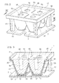
Figure 3 is a sectional view, taken along the plane of section III-III ofFigure 2 ; -
Figure 4 is a perspective, exploded view showing the lighting module according to the invention with an optical converter; and -
Figure 5 is an enlarged, cross-sectional view of the optical converter, taken along the plane of section V-V ofFigure 4 . - The lighting module according to the invention, designated as a whole with the
reference numeral 1, is described with the aid of the figures. - With reference for now to
Figure 1 , thelighting module 1 comprises a printed circuit board (PCB) 2 on which fourLEDs 3 are mounted, a holder 4 adapted to be disposed on theboard 2 and anoptical assembly 5 adapted to be retained by the holder 4. - The printed
circuit board 2 is substantially square or rectangular in shape, and the fourLEDs 3 are disposed on theboard 2 to form a matrix of two rows and two columns. TheLEDs 3 are preferably arranged according to the corners of a square. Furthermore, theLEDs 3 are arranged at a short distance from each other, for example at a distance smaller than 1 cm, so as to minimise the overall dimensions of themodule 1. - Each
LED 3 is preferably a high-efficiency one and has an electrical power of about 1.2 W and a luminous flux of 100-400 Lumens. In order to obtain a mixing of the light emitted by thelighting module 1, theLEDs 3 can preferably emit light of different colours, for example Red, Green, Blue and White. With the combination of these four basic colours a vast range of composite colours can be obtained. - The holder 4 comprises a
square base plate 40 around which asquare frame 41 is disposed. Fourtapered seats 42 with a diameter that decreases as the distance from thebase plate 40 increases are formed in thebase plate 40. Eachseat 42 is open at its ends and defines a paraboloid-in-shape cavity 43. - At the corners of the
base plate 40 are disposed fourlegs 44 of a length slightly greater than the length of theseats 42, so as to rest on the printedcircuit board 2 maintaining the bottom edge of theseats 42 in contact with theLEDs 3. Thelegs 44 can be fixed to the printedcircuit board 2 in any known manner, such as for example by click-in coupling, by soldering, by gluing or by means of other fixing systems. - A through
hole 45 is formed near the mid-point of one side edge of thebase plate 40 of the holder 4. - Returning to
Figure 1 , theoptical assembly 5 comprises asquare base plate 50, adapted to be disposed on thebase plate 40 of the holder 4, contained by theframe 41 of the holder 4. - Four paraboloid-in-
shape lenses 52, adapted to be inserted into therespective cavities 43 formed in theseats 42 of the holder 4, are connected to thebase plate 50 of theoptical assembly 5. Acylindrical centring pin 55 adapted to be inserted in thecentring hole 45 of thebase plate 40 of the holder 4 is connected to thebase plate 50 of theoptical assembly 5. - As shown in
Figure 3 , each paraboloid-in-shape lens 52 has on its axis a firstblind hole 56, open on thebase plate 50 and a secondblind hole 57 open at the bottom edge of thelens 52. - The first
blind hole 56 is substantially cylindrical or frustoconical in shape and the secondblind hole 57 is substantially paraboloid in shape and is adapted to receive the emitting part of theLED 3. - Cooling
slots 58 arranged cross-wise between theblind holes 56 are formed on thebase plate 50 of theoptical assembly 5. Theslots 58 pass through the wholeoptical assembly 5 between thelenses 52 and communicate withrespective gaps 48 between thelenses 52 and theseats 42 of the holder 4 wherein saidlens 52 are inserted. In this manner, the hot air on thecircuit board 2 is conveyed outside through saidgaps 48 and saidslots 58. - The
optical assembly 5 is produced in a single piece by injection moulding of a suitable transparent plastic material, such as, for example, methacrylate or PMMA (polymethylmethacrylate). - With reference to
Figures 4 and 5 , thelighting module 1 can include one or more optical converters 6 which serve to vary the optical aperture of the light beam leaving theoptical assembly 5. - The optical converter 6 is in the form of a sheet that is disposed inside the
frame 41 of the holder 4, above theflat base plate 50 of theoptical assembly 5. The optical converter 6 is snap fastened into theframe 41. For this purpose, the optical converter 6 has tworibs 66 which protrude from two opposite side edges thereof. Theribs 66 of the optical converter 6 engage inrespective apertures 146 formed in two opposite sides of theframe 41 of the holder 4. - The
optical assembly 5 also can have, in the opposite side edges of itsflat base plate 50,ribs 155 which, infigure 4 , are snap engage inrespective apertures 145 formed in the other two opposite sides of thesquare frame 41 of the holder 4. - The optical converter 6 can have a textured surface, according to the type of aperture of the light beam required.
- For example, to obtain a collimated light beam, that is, with a narrow angle of aperture (about 12°), the surface of the optical converter is left smooth.
- If, on the other hand, a light beam with a medium (25°) or a wide (45°) aperture is desired, the upper surface of the optical converter 6 is textured with more or less marked knurling, undulations or grooves according to the desired beam aperture.
- If a light beam with an oval or elliptical section is desired, the textured surface of the optical converter 6 is made to face towards the
flat base plate 50 of theoptical assembly 5. - In
Figures 4 and 5 an embodiment of the optical converter 6 is illustrated, in which its upper surface is textured so as to obtain an asymmetrical light beam F, having an inclination α = 6° with respect to a straight line at right angles to the plane of the optical converter. This solution is particularly suitable for lighting walls. - This result is obtained by making on the upper surface of the optical converter 6 prismatic ribs (60, 61), saw-toothed in shape in cross section, inclined towards the wall to be lit. In particular, less
inclined ribs 61 are formed in a central area and moreinclined ribs 60 are formed in the two lateral areas. The lateralprismatic ribs 60 have an angle of inclination β = 40° - 50° with respect to the plane of the optical converter 6. The centralprismatic ribs 61, on the other hand, have an angle of inclination γ = ¼ β with respect to the plane of the optical converter 6. - The optical converter 6 is made of the same material as the
optical assembly 5 and has a thickness of about 1-1.8 mm, depending upon the surface texturing. - Numerous changes and modifications of detail within the reach of a person skilled in the art can be made to the present embodiment of the invention without thereby departing from the scope of the invention as set forth in the appended claims.
Claims (15)
- A lighting module (1), in particular for lighting walls, comprising:- four LEDs (3) mounted, according to a square matrix, on an essentially square printed circuit board (2),- a holder (4) disposed on said printed circuit board (2) and provided with a square frame (41), and- an optical assembly (5) retained by said holder (4) and provided with four paraboloid-in-shape lenses (52) coupled to said four LEDs (3).
- A lighting module (1) according to claim 1, characterised in that said four LEDs (3) are disposed at the corners of a square.
- A lighting module (1) according to claim 1 or 2, characterised in that said four LEDs (3) are at a distance of less than 1 cm from each other.
- A lighting module (1) according to any one of the preceding claims, characterised by the fact that said four LEDs (3) emit light of different colours.
- A lighting module (1) according to any one of the preceding claims, characterised in that said optical assembly (5) comprises a square base plate (50) from which said paraboloid-in-shape lenses (52) protrude, the base plate (50) being adapted to be disposed inside said frame (41) of the holder (4).
- A lighting module (1) according to claim 5, characterised in that each paraboloid-in-shape lens (52) of said optical assembly (5) has axially a first blind hole (56) open on said base plate (50) and a second blind hole (57) open at the edge of the paraboloid-in-shape lens (52) and adapted to receive the light emission part of said LED (3).
- A lighting module (1) according to any one of the preceding claims, characterised in that said holder (4) comprises a base plate (40) from which protrude four tapered seats (42) defining respective cavities (43), adapted to accommodate said lenses (52) of the optical assembly (5).
- A lighting module (1) according to any one of the preceding claims, characterised in that said holder (4) comprises four legs (44) disposed at the four corners of the frame (41), adapted to be disposed on the circuit board (2) so as to keep the paraboloid-in-shape lenses (52) of the optical assembly (5) above said LEDs (3).
- A lighting module (1) according to any one of the preceding claims, characterised in that said optical assembly (5) is made in a single piece.
- A lighting module (1) according to any one of the preceding claims, characterised in that said optical assembly (5) comprises a centring pin (55) adapted to couple inside a centring hole (45) formed in said holder (4).
- A lighting module (1) according to any one of the preceding claims, characterised in that it comprises air slots (58) formed in said optical assembly (5) and gaps (48) between the lenses (52) and the tapered seats (42) of the holder (4) wherein said lenses (52) are inserted to convey outside the hot air on said circuit board (2).
- A lighting module (1) according to any one of the preceding claims, characterised in that it comprises at least one optical converter (6) disposed above said optical assembly (5) to vary the optical aperture of the light beam leaving the optical assembly (5).
- A lighting module (1) according to claim 12, characterised in that said optical converter (6) is a sheet of transparent material snap coupled into the peripheral frame (41) of said holder (4).
- A lighting module (1) according to claim 12 or 13, characterised in that on at least one surface said optical converter (6) has surface texturing in the form of knurling, of undulations or of ribs (60, 61).
- A lighting module (1) according to claim 14, characterised in that said optical converter (6) has prismatic ribs (60, 61) inclined towards the wall to be lit so as to obtain an asymmetrical beam with an inclination (α) of about 6° with respect to a straight line at right angles to the plane of said optical assembly (6).
Applications Claiming Priority (1)
| Application Number | Priority Date | Filing Date | Title |
|---|---|---|---|
| IT000141A ITMI20080141A1 (en) | 2008-01-30 | 2008-01-30 | LED LIGHTING MODULE |
Publications (2)
| Publication Number | Publication Date |
|---|---|
| EP2085680A1 true EP2085680A1 (en) | 2009-08-05 |
| EP2085680B1 EP2085680B1 (en) | 2011-01-12 |
Family
ID=40290154
Family Applications (1)
| Application Number | Title | Priority Date | Filing Date |
|---|---|---|---|
| EP09151044A Active EP2085680B1 (en) | 2008-01-30 | 2009-01-21 | Led lighting module |
Country Status (4)
| Country | Link |
|---|---|
| EP (1) | EP2085680B1 (en) |
| AT (1) | ATE495409T1 (en) |
| DE (1) | DE602009000540D1 (en) |
| IT (1) | ITMI20080141A1 (en) |
Cited By (10)
| Publication number | Priority date | Publication date | Assignee | Title |
|---|---|---|---|---|
| ITCR20100012A1 (en) * | 2010-04-16 | 2011-10-17 | Franco Venturini | LENS FOR LED PERFECTED |
| DE102012204997A1 (en) * | 2012-03-28 | 2013-10-02 | Ifm Electronic Gmbh | Optics support for light source module, has multiple support elements which have centering pin at end for engagement in centering opening of light source support, where centering pin has two opposite-lying centering ribs |
| EP2674670A1 (en) * | 2012-06-12 | 2013-12-18 | Bartenbach Holding GmbH | Lamp and method for its production |
| WO2015061819A1 (en) * | 2013-10-28 | 2015-05-07 | Zizala Lichtsysteme Gmbh | Securing device for an optical body for a motor vehicle headlight |
| EP2871411A1 (en) * | 2013-11-06 | 2015-05-13 | Zumtobel Lighting GmbH | Optical element for a lamp, and lamp |
| WO2019032944A1 (en) * | 2017-08-10 | 2019-02-14 | Archangel Device Llc | Safety light |
| EP2503216B1 (en) * | 2009-11-17 | 2021-04-14 | Enplas Corporation | Surface light-emitting unit and display device provided with the same |
| EP3221185B1 (en) * | 2014-11-18 | 2022-06-22 | Renault s.a.s | Lighting unit for a vehicle and corresponding vehicle |
| WO2023131526A1 (en) * | 2022-01-06 | 2023-07-13 | Signify Holding B.V. | Cluster linear cup optics |
| US11739928B2 (en) | 2017-08-10 | 2023-08-29 | Archangel Device Llc | Safety light |
Citations (3)
| Publication number | Priority date | Publication date | Assignee | Title |
|---|---|---|---|---|
| WO2003048637A1 (en) * | 2001-12-06 | 2003-06-12 | Fraen Corporation S.R.L. | High-heat-dissipation lighting module |
| GB2391702A (en) * | 2002-06-07 | 2004-02-11 | Polymer Optics Ltd | Modular optical system |
| WO2006097067A1 (en) * | 2005-03-16 | 2006-09-21 | Osram Opto Semiconductors Gmbh | Light-emitting module comprising leds and dowel pins for assembling an optical element |
-
2008
- 2008-01-30 IT IT000141A patent/ITMI20080141A1/en unknown
-
2009
- 2009-01-21 AT AT09151044T patent/ATE495409T1/en not_active IP Right Cessation
- 2009-01-21 DE DE602009000540T patent/DE602009000540D1/en active Active
- 2009-01-21 EP EP09151044A patent/EP2085680B1/en active Active
Patent Citations (3)
| Publication number | Priority date | Publication date | Assignee | Title |
|---|---|---|---|---|
| WO2003048637A1 (en) * | 2001-12-06 | 2003-06-12 | Fraen Corporation S.R.L. | High-heat-dissipation lighting module |
| GB2391702A (en) * | 2002-06-07 | 2004-02-11 | Polymer Optics Ltd | Modular optical system |
| WO2006097067A1 (en) * | 2005-03-16 | 2006-09-21 | Osram Opto Semiconductors Gmbh | Light-emitting module comprising leds and dowel pins for assembling an optical element |
Cited By (18)
| Publication number | Priority date | Publication date | Assignee | Title |
|---|---|---|---|---|
| EP2503216B1 (en) * | 2009-11-17 | 2021-04-14 | Enplas Corporation | Surface light-emitting unit and display device provided with the same |
| WO2011128926A1 (en) * | 2010-04-16 | 2011-10-20 | Franco Venturini | Improved lens for led |
| ITCR20100012A1 (en) * | 2010-04-16 | 2011-10-17 | Franco Venturini | LENS FOR LED PERFECTED |
| DE102012204997A1 (en) * | 2012-03-28 | 2013-10-02 | Ifm Electronic Gmbh | Optics support for light source module, has multiple support elements which have centering pin at end for engagement in centering opening of light source support, where centering pin has two opposite-lying centering ribs |
| DE102012204997B4 (en) * | 2012-03-28 | 2017-03-23 | Ifm Electronic Gmbh | optics carrier |
| EP2674670A1 (en) * | 2012-06-12 | 2013-12-18 | Bartenbach Holding GmbH | Lamp and method for its production |
| WO2015061819A1 (en) * | 2013-10-28 | 2015-05-07 | Zizala Lichtsysteme Gmbh | Securing device for an optical body for a motor vehicle headlight |
| US10173578B2 (en) | 2013-10-28 | 2019-01-08 | Zkw Group Gmbh | Securing device for an optical body for a motor vehicle headlight |
| EP2871411A1 (en) * | 2013-11-06 | 2015-05-13 | Zumtobel Lighting GmbH | Optical element for a lamp, and lamp |
| EP3221185B1 (en) * | 2014-11-18 | 2022-06-22 | Renault s.a.s | Lighting unit for a vehicle and corresponding vehicle |
| US10976046B2 (en) | 2017-08-10 | 2021-04-13 | Archangel Device Llc | Safety light |
| CN109386756A (en) * | 2017-08-10 | 2019-02-26 | 阿驰安吉设备有限责任公司 | Safety lamp |
| WO2019032944A1 (en) * | 2017-08-10 | 2019-02-14 | Archangel Device Llc | Safety light |
| US11397002B2 (en) | 2017-08-10 | 2022-07-26 | Archangel Device Llc | Safety light |
| TWI787321B (en) * | 2017-08-10 | 2022-12-21 | 美商大天使裝置有限責任公司 | Safety light |
| US11739928B2 (en) | 2017-08-10 | 2023-08-29 | Archangel Device Llc | Safety light |
| US12066178B2 (en) | 2017-08-10 | 2024-08-20 | Archangel Device Llc | System and method for portable, safety lighting |
| WO2023131526A1 (en) * | 2022-01-06 | 2023-07-13 | Signify Holding B.V. | Cluster linear cup optics |
Also Published As
| Publication number | Publication date |
|---|---|
| EP2085680B1 (en) | 2011-01-12 |
| ITMI20080141A1 (en) | 2009-07-31 |
| DE602009000540D1 (en) | 2011-02-24 |
| ATE495409T1 (en) | 2011-01-15 |
Similar Documents
| Publication | Publication Date | Title |
|---|---|---|
| EP2085680B1 (en) | Led lighting module | |
| KR101111274B1 (en) | Led lighting | |
| US8585237B2 (en) | Lighting module | |
| US9964696B2 (en) | Lighting module | |
| US8740437B2 (en) | Lighting module and lighting apparatus including the same | |
| TWI430469B (en) | Led lamp system | |
| EP1808640B1 (en) | Light emitting device | |
| US10837619B2 (en) | Optical system for multi-emitter LED-based lighting devices | |
| US20160252226A1 (en) | Vehicle lamp | |
| EP1729350A3 (en) | Light emitting diode package | |
| US20110149596A1 (en) | Led lamp having light guide | |
| US20120155114A1 (en) | Lighting module | |
| US9563008B2 (en) | Lighting module and lighting apparatus including the same | |
| JP2014089894A (en) | Illumination lamp | |
| EP3511613A1 (en) | Lens, light source module, and lighting device | |
| GB2391702A (en) | Modular optical system | |
| EP4146981B1 (en) | Illumination device | |
| CN210624230U (en) | Multi-angle transformation structure and linear lamp | |
| JP2010175606A (en) | Display plate of light-emitting diode type, and thin and long illumination tool | |
| KR101827712B1 (en) | Lighting module | |
| JP5855851B2 (en) | Light emitting device | |
| KR101272689B1 (en) | Lighting module | |
| KR101839868B1 (en) | Lighting module | |
| JP2023104622A (en) | Luminous flux control member, light emitting device, surface light source device and display device | |
| KR101827710B1 (en) | Lighting module |
Legal Events
| Date | Code | Title | Description |
|---|---|---|---|
| PUAI | Public reference made under article 153(3) epc to a published international application that has entered the european phase |
Free format text: ORIGINAL CODE: 0009012 |
|
| AK | Designated contracting states |
Kind code of ref document: A1 Designated state(s): AT BE BG CH CY CZ DE DK EE ES FI FR GB GR HR HU IE IS IT LI LT LU LV MC MK MT NL NO PL PT RO SE SI SK TR |
|
| AX | Request for extension of the european patent |
Extension state: AL BA RS |
|
| 17P | Request for examination filed |
Effective date: 20091111 |
|
| AKX | Designation fees paid |
Designated state(s): AT BE BG CH CY CZ DE DK EE ES FI FR GB GR HR HU IE IS IT LI LT LU LV MC MK MT NL NO PL PT RO SE SI SK TR |
|
| RIC1 | Information provided on ipc code assigned before grant |
Ipc: F21K 99/00 20100101AFI20100730BHEP |
|
| GRAP | Despatch of communication of intention to grant a patent |
Free format text: ORIGINAL CODE: EPIDOSNIGR1 |
|
| GRAS | Grant fee paid |
Free format text: ORIGINAL CODE: EPIDOSNIGR3 |
|
| GRAA | (expected) grant |
Free format text: ORIGINAL CODE: 0009210 |
|
| AK | Designated contracting states |
Kind code of ref document: B1 Designated state(s): AT BE BG CH CY CZ DE DK EE ES FI FR GB GR HR HU IE IS IT LI LT LU LV MC MK MT NL NO PL PT RO SE SI SK TR |
|
| REG | Reference to a national code |
Ref country code: GB Ref legal event code: FG4D |
|
| REG | Reference to a national code |
Ref country code: CH Ref legal event code: EP |
|
| REG | Reference to a national code |
Ref country code: IE Ref legal event code: FG4D |
|
| REF | Corresponds to: |
Ref document number: 602009000540 Country of ref document: DE Date of ref document: 20110224 Kind code of ref document: P |
|
| REG | Reference to a national code |
Ref country code: DE Ref legal event code: R096 Ref document number: 602009000540 Country of ref document: DE Effective date: 20110224 |
|
| REG | Reference to a national code |
Ref country code: NL Ref legal event code: VDEP Effective date: 20110112 |
|
| LTIE | Lt: invalidation of european patent or patent extension |
Effective date: 20110112 |
|
| PG25 | Lapsed in a contracting state [announced via postgrant information from national office to epo] |
Ref country code: GR Free format text: LAPSE BECAUSE OF FAILURE TO SUBMIT A TRANSLATION OF THE DESCRIPTION OR TO PAY THE FEE WITHIN THE PRESCRIBED TIME-LIMIT Effective date: 20110413 Ref country code: ES Free format text: LAPSE BECAUSE OF FAILURE TO SUBMIT A TRANSLATION OF THE DESCRIPTION OR TO PAY THE FEE WITHIN THE PRESCRIBED TIME-LIMIT Effective date: 20110423 Ref country code: NO Free format text: LAPSE BECAUSE OF FAILURE TO SUBMIT A TRANSLATION OF THE DESCRIPTION OR TO PAY THE FEE WITHIN THE PRESCRIBED TIME-LIMIT Effective date: 20110412 Ref country code: SE Free format text: LAPSE BECAUSE OF FAILURE TO SUBMIT A TRANSLATION OF THE DESCRIPTION OR TO PAY THE FEE WITHIN THE PRESCRIBED TIME-LIMIT Effective date: 20110112 Ref country code: LT Free format text: LAPSE BECAUSE OF FAILURE TO SUBMIT A TRANSLATION OF THE DESCRIPTION OR TO PAY THE FEE WITHIN THE PRESCRIBED TIME-LIMIT Effective date: 20110112 Ref country code: LV Free format text: LAPSE BECAUSE OF FAILURE TO SUBMIT A TRANSLATION OF THE DESCRIPTION OR TO PAY THE FEE WITHIN THE PRESCRIBED TIME-LIMIT Effective date: 20110112 Ref country code: IS Free format text: LAPSE BECAUSE OF FAILURE TO SUBMIT A TRANSLATION OF THE DESCRIPTION OR TO PAY THE FEE WITHIN THE PRESCRIBED TIME-LIMIT Effective date: 20110512 Ref country code: PT Free format text: LAPSE BECAUSE OF FAILURE TO SUBMIT A TRANSLATION OF THE DESCRIPTION OR TO PAY THE FEE WITHIN THE PRESCRIBED TIME-LIMIT Effective date: 20110512 Ref country code: HR Free format text: LAPSE BECAUSE OF FAILURE TO SUBMIT A TRANSLATION OF THE DESCRIPTION OR TO PAY THE FEE WITHIN THE PRESCRIBED TIME-LIMIT Effective date: 20110112 |
|
| PG25 | Lapsed in a contracting state [announced via postgrant information from national office to epo] |
Ref country code: BG Free format text: LAPSE BECAUSE OF FAILURE TO SUBMIT A TRANSLATION OF THE DESCRIPTION OR TO PAY THE FEE WITHIN THE PRESCRIBED TIME-LIMIT Effective date: 20110412 Ref country code: NL Free format text: LAPSE BECAUSE OF FAILURE TO SUBMIT A TRANSLATION OF THE DESCRIPTION OR TO PAY THE FEE WITHIN THE PRESCRIBED TIME-LIMIT Effective date: 20110112 Ref country code: AT Free format text: LAPSE BECAUSE OF FAILURE TO SUBMIT A TRANSLATION OF THE DESCRIPTION OR TO PAY THE FEE WITHIN THE PRESCRIBED TIME-LIMIT Effective date: 20110112 Ref country code: MC Free format text: LAPSE BECAUSE OF NON-PAYMENT OF DUE FEES Effective date: 20110131 Ref country code: SI Free format text: LAPSE BECAUSE OF FAILURE TO SUBMIT A TRANSLATION OF THE DESCRIPTION OR TO PAY THE FEE WITHIN THE PRESCRIBED TIME-LIMIT Effective date: 20110112 Ref country code: FI Free format text: LAPSE BECAUSE OF FAILURE TO SUBMIT A TRANSLATION OF THE DESCRIPTION OR TO PAY THE FEE WITHIN THE PRESCRIBED TIME-LIMIT Effective date: 20110112 Ref country code: CY Free format text: LAPSE BECAUSE OF FAILURE TO SUBMIT A TRANSLATION OF THE DESCRIPTION OR TO PAY THE FEE WITHIN THE PRESCRIBED TIME-LIMIT Effective date: 20110112 Ref country code: BE Free format text: LAPSE BECAUSE OF FAILURE TO SUBMIT A TRANSLATION OF THE DESCRIPTION OR TO PAY THE FEE WITHIN THE PRESCRIBED TIME-LIMIT Effective date: 20110112 Ref country code: PL Free format text: LAPSE BECAUSE OF FAILURE TO SUBMIT A TRANSLATION OF THE DESCRIPTION OR TO PAY THE FEE WITHIN THE PRESCRIBED TIME-LIMIT Effective date: 20110112 |
|
| REG | Reference to a national code |
Ref country code: IE Ref legal event code: MM4A |
|
| PG25 | Lapsed in a contracting state [announced via postgrant information from national office to epo] |
Ref country code: DK Free format text: LAPSE BECAUSE OF FAILURE TO SUBMIT A TRANSLATION OF THE DESCRIPTION OR TO PAY THE FEE WITHIN THE PRESCRIBED TIME-LIMIT Effective date: 20110112 Ref country code: EE Free format text: LAPSE BECAUSE OF FAILURE TO SUBMIT A TRANSLATION OF THE DESCRIPTION OR TO PAY THE FEE WITHIN THE PRESCRIBED TIME-LIMIT Effective date: 20110112 |
|
| PLBE | No opposition filed within time limit |
Free format text: ORIGINAL CODE: 0009261 |
|
| STAA | Information on the status of an ep patent application or granted ep patent |
Free format text: STATUS: NO OPPOSITION FILED WITHIN TIME LIMIT |
|
| PG25 | Lapsed in a contracting state [announced via postgrant information from national office to epo] |
Ref country code: CZ Free format text: LAPSE BECAUSE OF FAILURE TO SUBMIT A TRANSLATION OF THE DESCRIPTION OR TO PAY THE FEE WITHIN THE PRESCRIBED TIME-LIMIT Effective date: 20110112 Ref country code: RO Free format text: LAPSE BECAUSE OF FAILURE TO SUBMIT A TRANSLATION OF THE DESCRIPTION OR TO PAY THE FEE WITHIN THE PRESCRIBED TIME-LIMIT Effective date: 20110112 Ref country code: SK Free format text: LAPSE BECAUSE OF FAILURE TO SUBMIT A TRANSLATION OF THE DESCRIPTION OR TO PAY THE FEE WITHIN THE PRESCRIBED TIME-LIMIT Effective date: 20110112 |
|
| REG | Reference to a national code |
Ref country code: DE Ref legal event code: R119 Ref document number: 602009000540 Country of ref document: DE Effective date: 20110802 |
|
| 26N | No opposition filed |
Effective date: 20111013 |
|
| PG25 | Lapsed in a contracting state [announced via postgrant information from national office to epo] |
Ref country code: MT Free format text: LAPSE BECAUSE OF FAILURE TO SUBMIT A TRANSLATION OF THE DESCRIPTION OR TO PAY THE FEE WITHIN THE PRESCRIBED TIME-LIMIT Effective date: 20110112 |
|
| PG25 | Lapsed in a contracting state [announced via postgrant information from national office to epo] |
Ref country code: IE Free format text: LAPSE BECAUSE OF NON-PAYMENT OF DUE FEES Effective date: 20110121 |
|
| PG25 | Lapsed in a contracting state [announced via postgrant information from national office to epo] |
Ref country code: MK Free format text: LAPSE BECAUSE OF FAILURE TO SUBMIT A TRANSLATION OF THE DESCRIPTION OR TO PAY THE FEE WITHIN THE PRESCRIBED TIME-LIMIT Effective date: 20110112 |
|
| PG25 | Lapsed in a contracting state [announced via postgrant information from national office to epo] |
Ref country code: LU Free format text: LAPSE BECAUSE OF NON-PAYMENT OF DUE FEES Effective date: 20110121 |
|
| PG25 | Lapsed in a contracting state [announced via postgrant information from national office to epo] |
Ref country code: DE Free format text: LAPSE BECAUSE OF NON-PAYMENT OF DUE FEES Effective date: 20110802 |
|
| REG | Reference to a national code |
Ref country code: CH Ref legal event code: PL |
|
| PG25 | Lapsed in a contracting state [announced via postgrant information from national office to epo] |
Ref country code: TR Free format text: LAPSE BECAUSE OF FAILURE TO SUBMIT A TRANSLATION OF THE DESCRIPTION OR TO PAY THE FEE WITHIN THE PRESCRIBED TIME-LIMIT Effective date: 20110112 |
|
| PG25 | Lapsed in a contracting state [announced via postgrant information from national office to epo] |
Ref country code: HU Free format text: LAPSE BECAUSE OF FAILURE TO SUBMIT A TRANSLATION OF THE DESCRIPTION OR TO PAY THE FEE WITHIN THE PRESCRIBED TIME-LIMIT Effective date: 20110112 Ref country code: CH Free format text: LAPSE BECAUSE OF NON-PAYMENT OF DUE FEES Effective date: 20130131 Ref country code: LI Free format text: LAPSE BECAUSE OF NON-PAYMENT OF DUE FEES Effective date: 20130131 |
|
| REG | Reference to a national code |
Ref country code: FR Ref legal event code: PLFP Year of fee payment: 8 |
|
| REG | Reference to a national code |
Ref country code: FR Ref legal event code: PLFP Year of fee payment: 9 |
|
| REG | Reference to a national code |
Ref country code: FR Ref legal event code: PLFP Year of fee payment: 10 |
|
| P01 | Opt-out of the competence of the unified patent court (upc) registered |
Effective date: 20230530 |
|
| PGFP | Annual fee paid to national office [announced via postgrant information from national office to epo] |
Ref country code: GB Payment date: 20240108 Year of fee payment: 16 |
|
| PGFP | Annual fee paid to national office [announced via postgrant information from national office to epo] |
Ref country code: IT Payment date: 20231113 Year of fee payment: 16 Ref country code: FR Payment date: 20240124 Year of fee payment: 16 |