EP2085662A1 - Clutch control system for transmission - Google Patents
Clutch control system for transmission Download PDFInfo
- Publication number
- EP2085662A1 EP2085662A1 EP08162509A EP08162509A EP2085662A1 EP 2085662 A1 EP2085662 A1 EP 2085662A1 EP 08162509 A EP08162509 A EP 08162509A EP 08162509 A EP08162509 A EP 08162509A EP 2085662 A1 EP2085662 A1 EP 2085662A1
- Authority
- EP
- European Patent Office
- Prior art keywords
- oil
- clutch
- transmission
- engine
- control system
- Prior art date
- Legal status (The legal status is an assumption and is not a legal conclusion. Google has not performed a legal analysis and makes no representation as to the accuracy of the status listed.)
- Granted
Links
Images



Classifications
-
- F—MECHANICAL ENGINEERING; LIGHTING; HEATING; WEAPONS; BLASTING
- F16—ENGINEERING ELEMENTS AND UNITS; GENERAL MEASURES FOR PRODUCING AND MAINTAINING EFFECTIVE FUNCTIONING OF MACHINES OR INSTALLATIONS; THERMAL INSULATION IN GENERAL
- F16H—GEARING
- F16H61/00—Control functions within control units of change-speed- or reversing-gearings for conveying rotary motion ; Control of exclusively fluid gearing, friction gearing, gearings with endless flexible members or other particular types of gearing
- F16H61/68—Control functions within control units of change-speed- or reversing-gearings for conveying rotary motion ; Control of exclusively fluid gearing, friction gearing, gearings with endless flexible members or other particular types of gearing specially adapted for stepped gearings
- F16H61/684—Control functions within control units of change-speed- or reversing-gearings for conveying rotary motion ; Control of exclusively fluid gearing, friction gearing, gearings with endless flexible members or other particular types of gearing specially adapted for stepped gearings without interruption of drive
- F16H61/688—Control functions within control units of change-speed- or reversing-gearings for conveying rotary motion ; Control of exclusively fluid gearing, friction gearing, gearings with endless flexible members or other particular types of gearing specially adapted for stepped gearings without interruption of drive with two inputs, e.g. selection of one of two torque-flow paths by clutches
-
- F—MECHANICAL ENGINEERING; LIGHTING; HEATING; WEAPONS; BLASTING
- F16—ENGINEERING ELEMENTS AND UNITS; GENERAL MEASURES FOR PRODUCING AND MAINTAINING EFFECTIVE FUNCTIONING OF MACHINES OR INSTALLATIONS; THERMAL INSULATION IN GENERAL
- F16D—COUPLINGS FOR TRANSMITTING ROTATION; CLUTCHES; BRAKES
- F16D48/00—External control of clutches
- F16D48/06—Control by electric or electronic means, e.g. of fluid pressure
- F16D48/08—Regulating clutch take-up on starting
-
- F—MECHANICAL ENGINEERING; LIGHTING; HEATING; WEAPONS; BLASTING
- F16—ENGINEERING ELEMENTS AND UNITS; GENERAL MEASURES FOR PRODUCING AND MAINTAINING EFFECTIVE FUNCTIONING OF MACHINES OR INSTALLATIONS; THERMAL INSULATION IN GENERAL
- F16H—GEARING
- F16H61/00—Control functions within control units of change-speed- or reversing-gearings for conveying rotary motion ; Control of exclusively fluid gearing, friction gearing, gearings with endless flexible members or other particular types of gearing
- F16H61/0021—Generation or control of line pressure
-
- F—MECHANICAL ENGINEERING; LIGHTING; HEATING; WEAPONS; BLASTING
- F16—ENGINEERING ELEMENTS AND UNITS; GENERAL MEASURES FOR PRODUCING AND MAINTAINING EFFECTIVE FUNCTIONING OF MACHINES OR INSTALLATIONS; THERMAL INSULATION IN GENERAL
- F16D—COUPLINGS FOR TRANSMITTING ROTATION; CLUTCHES; BRAKES
- F16D2500/00—External control of clutches by electric or electronic means
- F16D2500/10—System to be controlled
- F16D2500/102—Actuator
- F16D2500/1026—Hydraulic
-
- F—MECHANICAL ENGINEERING; LIGHTING; HEATING; WEAPONS; BLASTING
- F16—ENGINEERING ELEMENTS AND UNITS; GENERAL MEASURES FOR PRODUCING AND MAINTAINING EFFECTIVE FUNCTIONING OF MACHINES OR INSTALLATIONS; THERMAL INSULATION IN GENERAL
- F16D—COUPLINGS FOR TRANSMITTING ROTATION; CLUTCHES; BRAKES
- F16D2500/00—External control of clutches by electric or electronic means
- F16D2500/10—System to be controlled
- F16D2500/108—Gear
- F16D2500/1086—Concentric shafts
-
- F—MECHANICAL ENGINEERING; LIGHTING; HEATING; WEAPONS; BLASTING
- F16—ENGINEERING ELEMENTS AND UNITS; GENERAL MEASURES FOR PRODUCING AND MAINTAINING EFFECTIVE FUNCTIONING OF MACHINES OR INSTALLATIONS; THERMAL INSULATION IN GENERAL
- F16D—COUPLINGS FOR TRANSMITTING ROTATION; CLUTCHES; BRAKES
- F16D2500/00—External control of clutches by electric or electronic means
- F16D2500/30—Signal inputs
- F16D2500/306—Signal inputs from the engine
- F16D2500/3067—Speed of the engine
-
- F—MECHANICAL ENGINEERING; LIGHTING; HEATING; WEAPONS; BLASTING
- F16—ENGINEERING ELEMENTS AND UNITS; GENERAL MEASURES FOR PRODUCING AND MAINTAINING EFFECTIVE FUNCTIONING OF MACHINES OR INSTALLATIONS; THERMAL INSULATION IN GENERAL
- F16D—COUPLINGS FOR TRANSMITTING ROTATION; CLUTCHES; BRAKES
- F16D2500/00—External control of clutches by electric or electronic means
- F16D2500/30—Signal inputs
- F16D2500/306—Signal inputs from the engine
- F16D2500/3069—Engine ignition switch
-
- F—MECHANICAL ENGINEERING; LIGHTING; HEATING; WEAPONS; BLASTING
- F16—ENGINEERING ELEMENTS AND UNITS; GENERAL MEASURES FOR PRODUCING AND MAINTAINING EFFECTIVE FUNCTIONING OF MACHINES OR INSTALLATIONS; THERMAL INSULATION IN GENERAL
- F16D—COUPLINGS FOR TRANSMITTING ROTATION; CLUTCHES; BRAKES
- F16D2500/00—External control of clutches by electric or electronic means
- F16D2500/50—Problem to be solved by the control system
- F16D2500/502—Relating the clutch
- F16D2500/50224—Drive-off
-
- F—MECHANICAL ENGINEERING; LIGHTING; HEATING; WEAPONS; BLASTING
- F16—ENGINEERING ELEMENTS AND UNITS; GENERAL MEASURES FOR PRODUCING AND MAINTAINING EFFECTIVE FUNCTIONING OF MACHINES OR INSTALLATIONS; THERMAL INSULATION IN GENERAL
- F16D—COUPLINGS FOR TRANSMITTING ROTATION; CLUTCHES; BRAKES
- F16D2500/00—External control of clutches by electric or electronic means
- F16D2500/70—Details about the implementation of the control system
- F16D2500/702—Look-up tables
- F16D2500/70205—Clutch actuator
- F16D2500/70217—Pressure
-
- F—MECHANICAL ENGINEERING; LIGHTING; HEATING; WEAPONS; BLASTING
- F16—ENGINEERING ELEMENTS AND UNITS; GENERAL MEASURES FOR PRODUCING AND MAINTAINING EFFECTIVE FUNCTIONING OF MACHINES OR INSTALLATIONS; THERMAL INSULATION IN GENERAL
- F16D—COUPLINGS FOR TRANSMITTING ROTATION; CLUTCHES; BRAKES
- F16D2500/00—External control of clutches by electric or electronic means
- F16D2500/70—Details about the implementation of the control system
- F16D2500/704—Output parameters from the control unit; Target parameters to be controlled
- F16D2500/70402—Actuator parameters
- F16D2500/7041—Position
- F16D2500/70412—Clutch position change rate
-
- F—MECHANICAL ENGINEERING; LIGHTING; HEATING; WEAPONS; BLASTING
- F16—ENGINEERING ELEMENTS AND UNITS; GENERAL MEASURES FOR PRODUCING AND MAINTAINING EFFECTIVE FUNCTIONING OF MACHINES OR INSTALLATIONS; THERMAL INSULATION IN GENERAL
- F16D—COUPLINGS FOR TRANSMITTING ROTATION; CLUTCHES; BRAKES
- F16D2500/00—External control of clutches by electric or electronic means
- F16D2500/70—Details about the implementation of the control system
- F16D2500/704—Output parameters from the control unit; Target parameters to be controlled
- F16D2500/70402—Actuator parameters
- F16D2500/7041—Position
- F16D2500/70414—Quick displacement to clutch touch point
-
- F—MECHANICAL ENGINEERING; LIGHTING; HEATING; WEAPONS; BLASTING
- F16—ENGINEERING ELEMENTS AND UNITS; GENERAL MEASURES FOR PRODUCING AND MAINTAINING EFFECTIVE FUNCTIONING OF MACHINES OR INSTALLATIONS; THERMAL INSULATION IN GENERAL
- F16H—GEARING
- F16H2306/00—Shifting
- F16H2306/36—Filling the dead volume of actuators
-
- F—MECHANICAL ENGINEERING; LIGHTING; HEATING; WEAPONS; BLASTING
- F16—ENGINEERING ELEMENTS AND UNITS; GENERAL MEASURES FOR PRODUCING AND MAINTAINING EFFECTIVE FUNCTIONING OF MACHINES OR INSTALLATIONS; THERMAL INSULATION IN GENERAL
- F16H—GEARING
- F16H2312/00—Driving activities
- F16H2312/14—Going to, or coming from standby operation, e.g. for engine start-stop operation at traffic lights
-
- F—MECHANICAL ENGINEERING; LIGHTING; HEATING; WEAPONS; BLASTING
- F16—ENGINEERING ELEMENTS AND UNITS; GENERAL MEASURES FOR PRODUCING AND MAINTAINING EFFECTIVE FUNCTIONING OF MACHINES OR INSTALLATIONS; THERMAL INSULATION IN GENERAL
- F16H—GEARING
- F16H2312/00—Driving activities
- F16H2312/20—Start-up or shut-down
Definitions
- the present invention relates to a clutch control system for a transmission, particularly to a clutch control system for a transmission which can appropriately perform preparations for driving of a plurality of hydraulic clutches driven by oil pressures supplied from a hydraulic pump, at an engine starting time.
- Patent Document 1 discloses a clutch control system for a transmission having a plurality of clutches corresponding to a plurality of gear speeds, wherein at an engine starting time, an oil pressure generated by a hydraulic pump is automatically supplied into oil passages, whereby the oil passages are filled up with the working oil before a clutch driving command is issued, and a delay in clutch operation is prevented from being generated.
- Patent Document 1 Japanese Patent Laid-Open No. 2001-141045
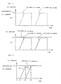
- FIG. 5 shows graphs illustrating an example of preparations for driving of clutches in a twin-clutch type transmission having two hydraulic clutches CL1 and CL2.
- the clutches CL1 and CL2 are so configured that they show strokes in the directions for connection, attendantly on the supply of the oil pressures, and a predetermined oil pressure Pc is set at such a value that CL1 and CL2 show sufficient strokes, to be switched into a connected state.
- the oil passages from which the working oil has been partly lost are again filled up with the working oil, and, for this purpose, it is aimed at generating the predetermined oil pressure Pc at each of CL1 and CL2.
- a master oil pressure Pm supplied from a hydraulic pump is so set as to have a little allowance (margin) in relation to the predetermined oil pressure Pc.
- the present invention has been made for solving the above-mentioned problems in the prior art. Accordingly, it is an object of the present invention to provide a clutch control system for a transmission which is capable of appropriately performing preparations for driving of a plurality of clutches driven by oil pressures supplied from a hydraulic pump, at an engine starting time.
- the present invention provides a clutch control system for a transmission having at least two hydraulic clutches, the clutch control system comprising: a hydraulic pump for supplying oil pressures for driving the hydraulic clutches; oil passages connected respectively to the hydraulic clutches so as to transmit the oil pressures; and a control unit for controlling the supplies of said oil pressures into said oil passages, characterized firstly in that upon detection of a starting operation of an engine, the control unit performs an initial preparatory operation for making preparations for driving of the hydraulic clutches by generating predetermined oil pressures in the oil passages, and the initial preparatory operation is carried out by supplying the oil pressures into the oil passages at different timings.
- the present invention is secondly characterized in that the hydraulic clutches include two hydraulic clutches, one on one side and one on the other side.
- the present invention is thirdly characterized in that the control unit, upon detection of the starting operation of the engine, starts supplying an oil pressure into the oil passage on one side, and starts supplying an oil pressure into the oil passage on the other side after the predetermined oil pressure is generated in the oil passage on one side.
- the present invention is fourthly characterized in that the transmission has a plurality of gear pairs between a main shaft and a counter shaft; the clutch on one side and the clutch on the other side are disposed on the main shaft and are operative to make and break transmission of a rotational driving force between the engine and the transmission; the main shaft includes an inner pipe for supporting odd-ordinal speed gears, and an outer pipe for supporting even-ordinal speed gears; the clutch on one side makes and breaks transmission of the rotational driving force to the inner pipe; and the clutch on the other side makes and breaks transmission of the rotational driving force to the outer pipe.
- the present invention is fifthly characterized in that the clutch on one side supports at least a first speed gear serving as a lowest speed gear.
- the present invention is sixthly characterized in that a pipeline connected to the hydraulic pump and a valve connected to the oil passage on one side and the oil passage on the other side are provided; and the valve is so configured that the destination of supply of the oil pressure generated in the hydraulic pump is changed over between the hydraulic pump and the oil passage on one side or the other side, based on a command from the control unit.
- the present invention is seventhly characterized in that the detection of the starting operation of the engine is carried out by detecting that the rotating speed of the engine has exceeded a predetermined value.
- the control unit upon detection of the starting operation of the engine the control unit performs the initial preparatory operation for making preparations for driving of the hydraulic clutches by generating predetermined oil pressures in the oil passages, and the initial preparatory operation is carried out by supplying the oil pressures into the oil passages at different timings. Therefore, the situation where the oil pressures are supplied into the oil passages at the same timing and an oil quantity in excess of the capacity of the hydraulic pump is needed is obviated in performing the initial preparatory operation, and the initial preparatory operation for the clutches can be carried out smoothly. This makes it possible to prevent an operational delay in relation to a first clutch driving command after the starting of the engine, and to enhance the response in regard of initial operations of the clutches.
- the capacity of the hydraulic pump can be suppressed to a low level, and a smaller-sized transmission can be contrived. Further, by arbitrarily selecting the sequence in which the oil pressures are supplied at the time of the initial preparatory operation, the preparation for driving of an arbitrary one of the clutches can be started earlier than that of the other clutch.
- the hydraulic clutches include the two clutches consisting of the clutch on one side and the clutch on the other side. Therefore, in the twin-clutch type transmission having the clutch on one side and the clutch on the other side, the initial preparatory operation for the hydraulic clutches can be carried out appropriately.
- the control unit upon detection of the starting operation of the engine, starts supplying an oil pressure into the oil passage on one side, and starts supplying an oil pressure into the oil passage on the other side after the predetermined oil pressure is generated in the oil passage on one side. Therefore, the preparation for driving of the clutch on one side can be completed earlier, as compared with the case where both the clutches are supplied with the predetermined oil pressures at the same time. Besides, since the preparation for driving of the clutch on the other side is started after the preparation for driving of the clutch on one side is completed, the clutch on one side can be driven before the preparation for driving of the clutch on the other side is completed.
- the transmission has a plurality of gear pairs between a main shaft and a counter shaft; the clutch on one side and the clutch on the other side are disposed on the main shaft and are operative to make and break transmission of a rotational driving force between the engine and the transmission;
- the main shaft includes an inner pipe for supporting odd-ordinal speed gears, and an outer pipe for supporting even-ordinal speed gears;
- the clutch on one side makes and breaks transmission of the rotational driving force to the inner pipe; and the clutch on the other side makes and breaks the transmission of the rotational driving force to the outer pipe.
- the clutch on one side supports at least a first speed gear serving as a lowest speed gear. Therefore, the period of time necessary for the lowest speed gear, which is highly frequently used at the time of vehicle starting, to be made usable is shortened, and a speedy vehicle starting after the starting of the engine can be achieved.
- a pipeline connected to the hydraulic pump and a valve connected to the oil passage on one side and the oil passage on the other side are provided; and the valve is so configured that the destination of supply of the oil pressure generated in the hydraulic pump is changed over between the hydraulic pump and the oil passage on one side or the other side, based on a command from the control unit. Therefore, in the transmission of the system in which the destination of supply of the oil pressure is selectively changed over between two clutches, the initial preparatory operation for the clutches can be carried out smoothly.
- the detection of the starting operation of the engine is carried out by detecting that the rotating speed of the engine has exceeded a predetermined value. Therefore, in the transmission in which the hydraulic pump is driven by a rotational driving force of the crankshaft, the initial preparatory operation for the clutches can be started after the supply of the oil pressure is started.
- FIG. 1 is a system block diagram of an automatic/manual transmission (hereinafter referred to as AMT) as an automatic transmission applied to a motorcycle and peripheral devices for the transmission.
- AMT 16 connected to an engine 11 is controlledly driven by a clutch hydraulic system 17 and an AMT control unit 18 as a transmission controller.
- the engine 11 has a throttle-by-wire type throttle body 19, and the throttle body 19 is provided with a motor 20 for opening and closing the throttle.
- the AMT 16 includes transmission gears 21 for a multiplicity of gear speeds, a first clutch 22, a second clutch 23, a shift drum 24, and a shift control motor 25 for turning the shift drum 24.
- a multiplicity of gears constituting the transmission gears 21 are respectively connected to or loosely fitted over a main shaft 26, a counter shaft 27, and a transmission gear output shaft 28.
- the main shaft 26a includes an inner main shaft 26a and an outer main shaft 26b. The inner main shaft 26a is connected to the first clutch 22, while the outer main shaft 26b is connected to the second clutch 23.
- the main shaft 26 and the counter shaft 27 are provided with clutches (not shown) capable of being displaced in the axial directions of the main shaft 26 and the counter shaft 27, and end parts of shift forks 29 are engaged respectively with these clutches and a camshaft (not shown) formed on the shift drum 24.
- a primary drive gear 31 is connected to an output shaft of the engine 11, i.e., a crankshaft 30, a primary drive gear 31 is connected, and the primary drive gear 31 is meshed with a primary driven gear 32.
- the primary driven gear 32 is connected to the inner main shaft 26a through the first clutch 22, and connected to the outer main shaft 26b through the second clutch 23.
- a counter shaft output gear 33 connected to the counter shaft 27 is meshed with an output driven gear 34 connected to the transmission gear output shaft 28.
- a drive sprocket 35 is connected to the transmission gear output shaft 28, and a driving force is transmitted to a rear wheel, serving as a drive wheel, through a drive chain (not shown) wrapped around the drive sprocket 35.
- the AMT 16 is provided therein with an engine speed sensor 36 disposed opposite to the periphery of the primary driven gear 32, and with a gear position sensor 38 for detecting the current gear position on the basis of the rotational position of the shift drum 24.
- the throttle body 19 is provided with a throttle sensor 47 for outputting a throttle position signal.
- the clutch hydraulic system 17 includes an oil tank 39, and a pipeline 40 for feeding an oil in the oil tank 39 to the first clutch 22 and the second clutch 23.
- a hydraulic pump 41 and a valve 42 are provided on the pipeline 40, and a regulator 44 is disposed on a return pipeline 43 connected to the pipeline 40.
- the valve 42 is so structured as to be able to individually exert oil pressures on the first clutch 22 and on the second clutch 23.
- the valve 42 is also provided with oil return pipelines 45.
- a mode switch 49 for switching between an automatic transmission (AT) mode and a manual transmission (MT) mode and a shift selection switch 50 for commanding a shift-up (UP) or a shift-down (DN) are connected to the AMT control unit 18.
- the AMT control unit 18 has a microcomputer (CPU), and is so configured as to be able to control the valve 42 and the shift control motor 25 according to output signals from various sensors and switches, and be able to change over the gear position in the AMT 16 automatically or semi-automatically.
- the AMT control unit 18 When an AT mode is selected, the AMT control unit 18 automatically changes over the transmission gears 21 according to such data as vehicle speed, engine speed, throttle position, etc. On the other hand, when an MT mode is selected, the AMT control unit 18 shifts up or shifts down the transmission gears 21 attendantly on a shift operation of the selection switch 50. Incidentally, even when the MT mode is selected, such a setting can be made as to carry out an auxiliary automatic transmission control for preventing over-rotation or stall of the engine from occurring.
- an oil pressure is exerted on the valve 42 by the hydraulic pump 41, and the oil pressure is controlled by the regulator 44 so as not to exceed an upper limit.
- the valve 42 is opened by a command from the AMT control unit 18, the oil pressure is applied to the first clutch 22 or the second clutch 23, and the primary driven gear 32 is connected to the inner main shaft 26a or the outer main shaft 26b through the first clutch 22 or the second clutch 23.
- the valve 42 is closed and the application of the oil pressure is stopped, the first clutch 22 and the second clutch 23 are urged by return springs (not shown) incorporated therein in such directions that the clutches are disconnected from the inner main shaft 26a and the outer main shaft 26b.
- the shift control motor 25 turns the shift drum 24 according to a command from the AMT control unit 18.
- the shift forks 29 are displaced in the axial direction of the shift drum 24 according to the shapes of cam grooves formed in the outer periphery of the shift drum 24, to move the clutches, whereby the meshing between the gears on the counter shaft 27 and the main shaft 26 is changed, and the transmission gears 21 are shifted up or down.
- FIG. 2 is an enlarged view of a part of FIG. 1 , showing the configuration in the periphery of an oil pressure supplying part.
- the same reference symbols as used above denote parts which are the same as or equivalent to those shown above.
- the valve 42 is composed of a first pressure control valve 42a for controlling the supply of an oil pressure to the first clutch 22, and a second pressure control valve 42b for controlling the supply of an oil pressure to the second clutch 23. Both the pressure control valves 42a and 42b are opened by driving commands sent from the AMT control unit 18.
- the operation of the valve 42 includes three patterns, namely, a pattern in which the first pressure control valve 42a is energized so as to supply the oil pressure into the oil passage 52, a pattern in which the second pressure control valve 42b is energized so as to supply the oil pressure into the oil passage 53, and a pattern in which energization of both the pressure control valves 42a and 42b is stopped so as to stop the supply of the oil pressure.
- the first clutch 22 and the second clutch 23 are both disconnected, resulting in a neutral condition where the rotational driving force of the engine is not transmitted.
- the AMT 16 is so configured that the inner main shaft 26a (see FIG. 1 ) connected to the first clutch 22 supports odd-ordinal speed gears (first, 3rd, and 5th speed gears), while the outer main shaft 26b (see FIG. 1 ) connected to the second clutch 23 support even-ordinal speed gears (2nd, and 4th speed gears).
- odd-ordinal speed gears first, 3rd, and 5th speed gears
- even-ordinal speed gears 2nd, and 4th speed gears
- the oil passages 52 and 53 are always filled with a working oil during the engine operation. Therefore, the master oil pressure Pm in the hydraulic pump 41 can be instantaneously transmitted to the first clutch 22 and the second clutch 23 according to a control of the driving of the valve 42.
- the working oil filling the oil passages 52 and 53 is used for lubrication between the inner main shaft 26a and the outer main shaft 26b (see FIG. 1 ) slid and rotated relative to each other and, simultaneously, circulated through various parts of the engine.
- FIG. 3 shows graphs illustrating an oil pressure supplying method for the initial preparatory operation according to an embodiment of the present invention.
- FIG. 3(a) shows target oil pressures for the first clutch 22 (hereinafter referred to as CL1) and the second clutch 23 (hereinafter referred to as CL2) in the initial preparatory operation
- FIG. 3(b) shows actual oil pressures actually generated in CL1 and CL2.
- a predetermined oil pressure Pc is set at such a pressure that CL1 and CL2 show sufficient strokes and are securely switched into the connected state.
- the AMT 16 according to this embodiment is so configured that CL1 supports the odd-ordinal speed gears and CL2 supports the even-ordinal speed gears, there is no possibility that the two clutches might be simultaneously put into the connected state during normal running of the vehicle. Therefore, it suffices for the master oil pressure Pm in the hydraulic pump 41 to be able to securely drive one of the two clutches; thus, the master oil pressure Pm is set at a value with some allowance in relation to the predetermined oil pressure Pc.
- the AMT control unit 18 first drives the valve 42 so as to start the supply of an oil pressure to CL1, and cause CL1 to reach the predetermined oil pressure Pc, thereby completing the preparation for driving of CL1.
- CL2 is caused to reach the predetermined oil pressure Pc, thereby completing the preparation for driving of CL2.
- the initial preparatory operation is carried out by supplying the oil pressures to CL1 and CL2, namely, into the oil passages 52 and 53 at different timings.
- This makes it possible to generate the actual oil pressures conforming to the target oil pressures at CL1 and CL2, even in the case of a transmission such that the master oil pressure Pm would be lowered if the oil pressures are simultaneously supplied to CL1 and CL2. Consequently, the preparation for driving of the clutches can be carried out smoothly.
- the AMT 16 according to this embodiment is so configured that CL1 is in charge of the odd-ordinal gear speeds while CL2 is in charge of the even-ordinal gear speeds, when the preparation for driving of CL1 is completed earlier, it is possible to shorten the time necessary for the first speed gear (lowest speed gear), which is highly possibly used at the time of vehicle starting after the starting of the engine, to become usable, and to achieve a swift vehicle starting after the starting of the engine.
- the first speed gear lowest speed gear
- the duration of supply of the oil pressures to CL1 and CL2 by the AMT control unit 18 can be set according to the lapse of time (for example, 0.5 sec) from the start of driving of the valve 42, instead of judging whether or not the oil pressures at CL1 and CL2 have actually reached the predetermined oil pressure Pc.
- FIG. 4 is a graph illustrating an oil pressure supplying method for the initial preparatory operation according to a modified example of the embodiment of the present invention.
- an oil pressure is supplied to CL1 earlier as an initial preparatory operation, and thereafter an oil pressure is supplied to CL2, in the same manner as in the above-described embodiment.
- This modified example is characterized in that the supply of the oil pressure to CL1 is started at time t1, and the supply of the oil pressure to CL2 is started simultaneously when the oil pressure P1 at CL1 reaches the predetermined oil pressure Pc at time t2.
- the clutch control system for a transmission based on the present invention upon detection of an engine starting operation, oil pressures are supplied at at least two different timings into oil passages arranged for supplying oil pressures to hydraulic clutches. Therefore, the situation in which oil pressures are supplied into the oil passages at the same timing and hence an oil quantity in excess of the capacity of a hydraulic pump is demanded can be obviated, and an initial preparatory operation for the clutches can be carried out smoothly. This makes it possible to prevent an operational delay with respect to a first clutch driving command after engine starting, and to enhance the response in regard of an initial clutch operation. Besides, since there is no need to supply oil pressures into the oil passages at the same timing, the capacity of the hydraulic pump can be suppressed to a low level, and a smaller-sized transmission can be contrived.
- the configurations of the transmission, the hydraulic pump and the valve, the relation between the master oil pressure of the hydraulic pump and the predetermined oil pressure, the times to supply the oil pressures to the clutches in the initial preparatory operation, the sequence in which the oil pressures are supplied to the plurality of clutches, etc. are not limited to those in the above-described embodiment, and may be modified variously.
- the sequence in which oil pressures are supplied to the plurality of clutches may be arbitrarily set; for instance, the oil pressure is supplied to one clutch earlier, and thereafter the oil pressures are supplied to the other two clutches at the same timing.
Landscapes
- Engineering & Computer Science (AREA)
- General Engineering & Computer Science (AREA)
- Mechanical Engineering (AREA)
- Physics & Mathematics (AREA)
- Fluid Mechanics (AREA)
- Control Of Transmission Device (AREA)
Abstract
Description
- The present invention relates to a clutch control system for a transmission, particularly to a clutch control system for a transmission which can appropriately perform preparations for driving of a plurality of hydraulic clutches driven by oil pressures supplied from a hydraulic pump, at an engine starting time.
- Hitherto, there has been known a transmission which has a hydraulic pump driven attendantly on the rotation of a crankshaft and in which connection/disconnection of a clutch is controlled by an oil pressure generated by the hydraulic pump. In such a hydraulic type clutch, when the supply of the oil pressure is stopped attendantly on stopping of the engine, a working oil filling up an oil passage for the purpose of transmitting the oil pressure may be lost little by little from the oil passage due to leakage through gaps present in lubricated parts, leakage from hydraulic devices, or the like. At the time of first driving the clutch by starting the engine under the condition where the working oil has been partly lost from the oil passage, even if the oil pressure is supplied from the hydraulic pump according to a clutch driving command, it would take a little time for the oil passage to be again filled up with the working oil. As a result, at the time of first driving the clutch after the starting of the engine, an operational delay may be generated in relation to the driving command.
-
Patent Document 1 discloses a clutch control system for a transmission having a plurality of clutches corresponding to a plurality of gear speeds, wherein at an engine starting time, an oil pressure generated by a hydraulic pump is automatically supplied into oil passages, whereby the oil passages are filled up with the working oil before a clutch driving command is issued, and a delay in clutch operation is prevented from being generated.
[Patent Document 1]
Japanese Patent Laid-Open No.2001-141045 - In the technology according to
Patent Document 1, however, in order to fill up the oil passages connected to the plurality of clutches with the working oil, the respective times to supply the oil pressures into the oil passages are computed from pipeline volume, engine speed and oil temperature, so that a complicated control is needed. - In addition, where the above-mentioned computation of the times to supply the oil pressures is not conducted and the oil pressures are supplied into the plurality of oil passages at the same time, the following problem may be generated.
FIG. 5 shows graphs illustrating an example of preparations for driving of clutches in a twin-clutch type transmission having two hydraulic clutches CL1 and CL2. The clutches CL1 and CL2 are so configured that they show strokes in the directions for connection, attendantly on the supply of the oil pressures, and a predetermined oil pressure Pc is set at such a value that CL1 and CL2 show sufficient strokes, to be switched into a connected state. In this example, as preparations for driving of the clutches, the oil passages from which the working oil has been partly lost are again filled up with the working oil, and, for this purpose, it is aimed at generating the predetermined oil pressure Pc at each of CL1 and CL2. In addition, a master oil pressure Pm supplied from a hydraulic pump is so set as to have a little allowance (margin) in relation to the predetermined oil pressure Pc. - In this case, if the supplies of oil pressures to CL1 and CL2 are simultaneously started so as to realize the target oil pressure shown in
FIG. 5(a) , a working oil quantity in excess of a supply quantity such that the hydraulic pump can maintain the master oil pressure Pm is needed instantaneously. This results in that the master oil pressure Pm is lowered, and, as shown inFIG. 5(b) , actual oil pressures generated at CL1 and CL2 do not conform to the target oil pressure, and the preparations for driving of the clutches are not carried out smoothly. Incidentally, although the lowering of the master oil pressure Pm can be prevented if the capacity of the hydraulic pump is increased sufficiently, it is undesirable to enlarge the hydraulic pump in order to secure the capacity that is needed only for the preparations for driving of the clutches. - The present invention has been made for solving the above-mentioned problems in the prior art. Accordingly, it is an object of the present invention to provide a clutch control system for a transmission which is capable of appropriately performing preparations for driving of a plurality of clutches driven by oil pressures supplied from a hydraulic pump, at an engine starting time.
- In order to attain the above object, the present invention provides a clutch control system for a transmission having at least two hydraulic clutches, the clutch control system comprising: a hydraulic pump for supplying oil pressures for driving the hydraulic clutches; oil passages connected respectively to the hydraulic clutches so as to transmit the oil pressures; and a control unit for controlling the supplies of said oil pressures into said oil passages, characterized firstly in that upon detection of a starting operation of an engine, the control unit performs an initial preparatory operation for making preparations for driving of the hydraulic clutches by generating predetermined oil pressures in the oil passages, and the initial preparatory operation is carried out by supplying the oil pressures into the oil passages at different timings.
- In addition, the present invention is secondly characterized in that the hydraulic clutches include two hydraulic clutches, one on one side and one on the other side.
- Besides, the present invention is thirdly characterized in that the control unit, upon detection of the starting operation of the engine, starts supplying an oil pressure into the oil passage on one side, and starts supplying an oil pressure into the oil passage on the other side after the predetermined oil pressure is generated in the oil passage on one side.
- Further, the present invention is fourthly characterized in that the transmission has a plurality of gear pairs between a main shaft and a counter shaft; the clutch on one side and the clutch on the other side are disposed on the main shaft and are operative to make and break transmission of a rotational driving force between the engine and the transmission; the main shaft includes an inner pipe for supporting odd-ordinal speed gears, and an outer pipe for supporting even-ordinal speed gears; the clutch on one side makes and breaks transmission of the rotational driving force to the inner pipe; and the clutch on the other side makes and breaks transmission of the rotational driving force to the outer pipe.
- In addition, the present invention is fifthly characterized in that the clutch on one side supports at least a first speed gear serving as a lowest speed gear.
- Besides, the present invention is sixthly characterized in that a pipeline connected to the hydraulic pump and a valve connected to the oil passage on one side and the oil passage on the other side are provided; and the valve is so configured that the destination of supply of the oil pressure generated in the hydraulic pump is changed over between the hydraulic pump and the oil passage on one side or the other side, based on a command from the control unit.
- Furthermore, the present invention is seventhly characterized in that the detection of the starting operation of the engine is carried out by detecting that the rotating speed of the engine has exceeded a predetermined value.
- According to the first characteristic of the present invention, upon detection of the starting operation of the engine the control unit performs the initial preparatory operation for making preparations for driving of the hydraulic clutches by generating predetermined oil pressures in the oil passages, and the initial preparatory operation is carried out by supplying the oil pressures into the oil passages at different timings. Therefore, the situation where the oil pressures are supplied into the oil passages at the same timing and an oil quantity in excess of the capacity of the hydraulic pump is needed is obviated in performing the initial preparatory operation, and the initial preparatory operation for the clutches can be carried out smoothly. This makes it possible to prevent an operational delay in relation to a first clutch driving command after the starting of the engine, and to enhance the response in regard of initial operations of the clutches. In addition, since it is unnecessary to supply the oil passages with the oil pressures at the same timing, the capacity of the hydraulic pump can be suppressed to a low level, and a smaller-sized transmission can be contrived. Further, by arbitrarily selecting the sequence in which the oil pressures are supplied at the time of the initial preparatory operation, the preparation for driving of an arbitrary one of the clutches can be started earlier than that of the other clutch.
- According to the second characteristic of the present invention, the hydraulic clutches include the two clutches consisting of the clutch on one side and the clutch on the other side. Therefore, in the twin-clutch type transmission having the clutch on one side and the clutch on the other side, the initial preparatory operation for the hydraulic clutches can be carried out appropriately.
- According to the third characteristic of the present invention, the control unit, upon detection of the starting operation of the engine, starts supplying an oil pressure into the oil passage on one side, and starts supplying an oil pressure into the oil passage on the other side after the predetermined oil pressure is generated in the oil passage on one side. Therefore, the preparation for driving of the clutch on one side can be completed earlier, as compared with the case where both the clutches are supplied with the predetermined oil pressures at the same time. Besides, since the preparation for driving of the clutch on the other side is started after the preparation for driving of the clutch on one side is completed, the clutch on one side can be driven before the preparation for driving of the clutch on the other side is completed.
- According to the fourth characteristic of the present invention, the transmission has a plurality of gear pairs between a main shaft and a counter shaft; the clutch on one side and the clutch on the other side are disposed on the main shaft and are operative to make and break transmission of a rotational driving force between the engine and the transmission; the main shaft includes an inner pipe for supporting odd-ordinal speed gears, and an outer pipe for supporting even-ordinal speed gears; the clutch on one side makes and breaks transmission of the rotational driving force to the inner pipe; and the clutch on the other side makes and breaks the transmission of the rotational driving force to the outer pipe. Therefore, in the twin-clutch type transmission in which the clutch on one side is in charge of odd-ordinal gear speeds and the clutch on the other side is in charge of even-ordinal gear speeds, the preparation for driving of the clutch on one side is completed early. This makes it possible to shorten the period of time necessary for the first speed gear, which is highly possibly used first after the starting of the engine, to be made usable.
- According to the fifth characteristic of the present invention, the clutch on one side supports at least a first speed gear serving as a lowest speed gear. Therefore, the period of time necessary for the lowest speed gear, which is highly frequently used at the time of vehicle starting, to be made usable is shortened, and a speedy vehicle starting after the starting of the engine can be achieved.
- According to the sixth characteristic of the present invention, a pipeline connected to the hydraulic pump and a valve connected to the oil passage on one side and the oil passage on the other side are provided; and the valve is so configured that the destination of supply of the oil pressure generated in the hydraulic pump is changed over between the hydraulic pump and the oil passage on one side or the other side, based on a command from the control unit. Therefore, in the transmission of the system in which the destination of supply of the oil pressure is selectively changed over between two clutches, the initial preparatory operation for the clutches can be carried out smoothly.
- According to the seventh characteristic of the present invention, the detection of the starting operation of the engine is carried out by detecting that the rotating speed of the engine has exceeded a predetermined value. Therefore, in the transmission in which the hydraulic pump is driven by a rotational driving force of the crankshaft, the initial preparatory operation for the clutches can be started after the supply of the oil pressure is started.
-
- [
FIG. 1 ]
FIG. 1 is a system block diagram of an automatic/manual transmission applied to a motorcycle, and peripheral devices therefor, according to an embodiment of the present invention. - [
FIG. 2 ]
FIG. 2 is an enlarged view of a part ofFIG. 1 , showing a configuration of the periphery of an oil pressure supplying part. - [
FIG. 3 ]
FIG. 3 shows graphs illustrating an oil pressure supplying method for an initial preparatory operation according to an embodiment of the present invention. - [
FIG. 4 ]
FIG. 4 shows a graph illustrating an oil pressure supplying method for the initial preparatory operation according to a modified example of the configuration of the present invention. - [
FIG. 5 ]
FIG. 5 shows graphs illustrating oil pressure variations in the case where oil pressures are supplied to CL1 and CL2 at the same time. - Now, a preferred embodiment of the present invention will be described below, referring to the drawings.
FIG. 1 is a system block diagram of an automatic/manual transmission (hereinafter referred to as AMT) as an automatic transmission applied to a motorcycle and peripheral devices for the transmission. The AMT 16 connected to anengine 11 is controlledly driven by a clutchhydraulic system 17 and anAMT control unit 18 as a transmission controller. Theengine 11 has a throttle-by-wiretype throttle body 19, and thethrottle body 19 is provided with amotor 20 for opening and closing the throttle. - The AMT 16 includes
transmission gears 21 for a multiplicity of gear speeds, afirst clutch 22, asecond clutch 23, ashift drum 24, and ashift control motor 25 for turning theshift drum 24. A multiplicity of gears constituting thetransmission gears 21 are respectively connected to or loosely fitted over amain shaft 26, acounter shaft 27, and a transmissiongear output shaft 28. Themain shaft 26a includes an innermain shaft 26a and an outermain shaft 26b. The innermain shaft 26a is connected to thefirst clutch 22, while the outermain shaft 26b is connected to thesecond clutch 23. Themain shaft 26 and thecounter shaft 27 are provided with clutches (not shown) capable of being displaced in the axial directions of themain shaft 26 and thecounter shaft 27, and end parts ofshift forks 29 are engaged respectively with these clutches and a camshaft (not shown) formed on theshift drum 24. - To an output shaft of the
engine 11, i.e., acrankshaft 30, aprimary drive gear 31 is connected, and theprimary drive gear 31 is meshed with a primary drivengear 32. The primary drivengear 32 is connected to the innermain shaft 26a through the first clutch 22, and connected to the outermain shaft 26b through thesecond clutch 23. - A counter
shaft output gear 33 connected to thecounter shaft 27 is meshed with an output drivengear 34 connected to the transmissiongear output shaft 28. Adrive sprocket 35 is connected to the transmissiongear output shaft 28, and a driving force is transmitted to a rear wheel, serving as a drive wheel, through a drive chain (not shown) wrapped around thedrive sprocket 35. In addition, theAMT 16 is provided therein with anengine speed sensor 36 disposed opposite to the periphery of the primary drivengear 32, and with agear position sensor 38 for detecting the current gear position on the basis of the rotational position of theshift drum 24. Besides, thethrottle body 19 is provided with athrottle sensor 47 for outputting a throttle position signal. - The clutch
hydraulic system 17 includes anoil tank 39, and apipeline 40 for feeding an oil in theoil tank 39 to the first clutch 22 and thesecond clutch 23. Ahydraulic pump 41 and avalve 42 are provided on thepipeline 40, and aregulator 44 is disposed on areturn pipeline 43 connected to thepipeline 40. Thevalve 42 is so structured as to be able to individually exert oil pressures on the first clutch 22 and on thesecond clutch 23. In addition, thevalve 42 is also provided withoil return pipelines 45. - A
mode switch 49 for switching between an automatic transmission (AT) mode and a manual transmission (MT) mode and ashift selection switch 50 for commanding a shift-up (UP) or a shift-down (DN) are connected to theAMT control unit 18. TheAMT control unit 18 has a microcomputer (CPU), and is so configured as to be able to control thevalve 42 and theshift control motor 25 according to output signals from various sensors and switches, and be able to change over the gear position in theAMT 16 automatically or semi-automatically. - When an AT mode is selected, the
AMT control unit 18 automatically changes over the transmission gears 21 according to such data as vehicle speed, engine speed, throttle position, etc. On the other hand, when an MT mode is selected, theAMT control unit 18 shifts up or shifts down the transmission gears 21 attendantly on a shift operation of theselection switch 50. Incidentally, even when the MT mode is selected, such a setting can be made as to carry out an auxiliary automatic transmission control for preventing over-rotation or stall of the engine from occurring. - In the clutch
hydraulic system 17, an oil pressure is exerted on thevalve 42 by thehydraulic pump 41, and the oil pressure is controlled by theregulator 44 so as not to exceed an upper limit. When thevalve 42 is opened by a command from theAMT control unit 18, the oil pressure is applied to the first clutch 22 or the second clutch 23, and the primary drivengear 32 is connected to the innermain shaft 26a or the outermain shaft 26b through the first clutch 22 or thesecond clutch 23. When thevalve 42 is closed and the application of the oil pressure is stopped, the first clutch 22 and the second clutch 23 are urged by return springs (not shown) incorporated therein in such directions that the clutches are disconnected from the innermain shaft 26a and the outermain shaft 26b. - The
shift control motor 25 turns theshift drum 24 according to a command from theAMT control unit 18. When theshift drum 24 is turned, theshift forks 29 are displaced in the axial direction of theshift drum 24 according to the shapes of cam grooves formed in the outer periphery of theshift drum 24, to move the clutches, whereby the meshing between the gears on thecounter shaft 27 and themain shaft 26 is changed, and the transmission gears 21 are shifted up or down. -
FIG. 2 is an enlarged view of a part ofFIG. 1 , showing the configuration in the periphery of an oil pressure supplying part. The same reference symbols as used above denote parts which are the same as or equivalent to those shown above. During an engine operation, a master oil pressure Pm regulated by the regulator 44 (seeFIG. 1 ) is generated in thehydraulic pump 41, and the master oil pressure Pm is supplied through thepipeline 40 to thevalve 42. Thevalve 42 is composed of a firstpressure control valve 42a for controlling the supply of an oil pressure to the first clutch 22, and a secondpressure control valve 42b for controlling the supply of an oil pressure to thesecond clutch 23. Both thepressure control valves AMT control unit 18. When the firstpressure control valve 42a is driven and the master oil pressure Pm is supplied into anoil passage 52, the first clutch 22 is driven and switched into a connected state. On the other hand, when the secondpressure control valve 42b is driven and the master oil pressure Pm is supplied into anoil passage 53, the second clutch 23 is switched into a connected state. Incidentally, the operation of thevalve 42 according to this embodiment includes three patterns, namely, a pattern in which the firstpressure control valve 42a is energized so as to supply the oil pressure into theoil passage 52, a pattern in which the secondpressure control valve 42b is energized so as to supply the oil pressure into theoil passage 53, and a pattern in which energization of both thepressure control valves - The
AMT 16 according to this embodiment is so configured that the innermain shaft 26a (seeFIG. 1 ) connected to the first clutch 22 supports odd-ordinal speed gears (first, 3rd, and 5th speed gears), while the outermain shaft 26b (seeFIG. 1 ) connected to the second clutch 23 support even-ordinal speed gears (2nd, and 4th speed gears). For example, during when the vehicle is running with an odd-ordinal speed gear selected, the supply of the oil pressure to the first clutch 22 is continued and the first clutch 22 is thereby kept in the connected state. When shift changes are sequentially carried out, the connected/disconnected states of the first clutch 22 and the second clutch 23 are changed over alternately. - The
oil passages hydraulic pump 41 can be instantaneously transmitted to the first clutch 22 and the second clutch 23 according to a control of the driving of thevalve 42. However, the working oil filling theoil passages main shaft 26a and the outermain shaft 26b (seeFIG. 1 ) slid and rotated relative to each other and, simultaneously, circulated through various parts of the engine. Therefore, when the supply of the oil pressure from thehydraulic pump 41 is stopped attendant on the stopping of the engine, the working oil filling up theoil passages - When the
engine 11 is started from the condition where the working oil has slightly escaped from any of theoil passages hydraulic pump 41 according to a first clutch driving command, it takes a little time for the oil passages to be again filled up with the working oil, so that there is a possibility of a delay in the clutch operation. In order to obviate the delay in the clutch operation, it suffices to perform preparation for driving wherein the oil pressure is so supplied as to fill up theoil passages oil passages -
FIG. 3 shows graphs illustrating an oil pressure supplying method for the initial preparatory operation according to an embodiment of the present invention.FIG. 3(a) shows target oil pressures for the first clutch 22 (hereinafter referred to as CL1) and the second clutch 23 (hereinafter referred to as CL2) in the initial preparatory operation, andFIG. 3(b) shows actual oil pressures actually generated in CL1 and CL2. - In this embodiment, a predetermined oil pressure Pc is set at such a pressure that CL1 and CL2 show sufficient strokes and are securely switched into the connected state. In addition, since the
AMT 16 according to this embodiment is so configured that CL1 supports the odd-ordinal speed gears and CL2 supports the even-ordinal speed gears, there is no possibility that the two clutches might be simultaneously put into the connected state during normal running of the vehicle. Therefore, it suffices for the master oil pressure Pm in thehydraulic pump 41 to be able to securely drive one of the two clutches; thus, the master oil pressure Pm is set at a value with some allowance in relation to the predetermined oil pressure Pc. - When the oil pressures in CL1 and CL2, or the oil pressures in the
oil passages FIG. 3 , when the engine starting operation is detected, theAMT control unit 18 first drives thevalve 42 so as to start the supply of an oil pressure to CL1, and cause CL1 to reach the predetermined oil pressure Pc, thereby completing the preparation for driving of CL1. Next, CL2 is caused to reach the predetermined oil pressure Pc, thereby completing the preparation for driving of CL2. By this, the initial preparatory operation for the two clutches CL1 and CL2 is completed. - As above-mentioned, according to the oil pressure supplying method in this embodiment, the initial preparatory operation is carried out by supplying the oil pressures to CL1 and CL2, namely, into the
oil passages - Besides, since the
AMT 16 according to this embodiment is so configured that CL1 is in charge of the odd-ordinal gear speeds while CL2 is in charge of the even-ordinal gear speeds, when the preparation for driving of CL1 is completed earlier, it is possible to shorten the time necessary for the first speed gear (lowest speed gear), which is highly possibly used at the time of vehicle starting after the starting of the engine, to become usable, and to achieve a swift vehicle starting after the starting of the engine. Incidentally, the duration of supply of the oil pressures to CL1 and CL2 by theAMT control unit 18 can be set according to the lapse of time (for example, 0.5 sec) from the start of driving of thevalve 42, instead of judging whether or not the oil pressures at CL1 and CL2 have actually reached the predetermined oil pressure Pc. -
FIG. 4 is a graph illustrating an oil pressure supplying method for the initial preparatory operation according to a modified example of the embodiment of the present invention. The same reference symbols as used above denote parts the same as or equivalent to those shown above. In this modified example, also, an oil pressure is supplied to CL1 earlier as an initial preparatory operation, and thereafter an oil pressure is supplied to CL2, in the same manner as in the above-described embodiment. This modified example is characterized in that the supply of the oil pressure to CL1 is started at time t1, and the supply of the oil pressure to CL2 is started simultaneously when the oil pressure P1 at CL1 reaches the predetermined oil pressure Pc at time t2. Therefore, the preparation for driving of CL1 is completed, and the first speed gear is thereby made selectable, at time t2, and then the preparation for driving of CL2 is completed at time t3. Consequently, the initial preparatory operation for CL1 and CL2 is completed in a minimized period of time. - As has been described above, according to the clutch control system for a transmission based on the present invention, upon detection of an engine starting operation, oil pressures are supplied at at least two different timings into oil passages arranged for supplying oil pressures to hydraulic clutches. Therefore, the situation in which oil pressures are supplied into the oil passages at the same timing and hence an oil quantity in excess of the capacity of a hydraulic pump is demanded can be obviated, and an initial preparatory operation for the clutches can be carried out smoothly. This makes it possible to prevent an operational delay with respect to a first clutch driving command after engine starting, and to enhance the response in regard of an initial clutch operation. Besides, since there is no need to supply oil pressures into the oil passages at the same timing, the capacity of the hydraulic pump can be suppressed to a low level, and a smaller-sized transmission can be contrived.
- Incidentally, the configurations of the transmission, the hydraulic pump and the valve, the relation between the master oil pressure of the hydraulic pump and the predetermined oil pressure, the times to supply the oil pressures to the clutches in the initial preparatory operation, the sequence in which the oil pressures are supplied to the plurality of clutches, etc. are not limited to those in the above-described embodiment, and may be modified variously. For example, in the case where three hydraulic clutches are provided, the sequence in which oil pressures are supplied to the plurality of clutches may be arbitrarily set; for instance, the oil pressure is supplied to one clutch earlier, and thereafter the oil pressures are supplied to the other two clutches at the same timing.
-
- 16: AMT (transmission),
- 22: First clutch (CL1, clutch on one side),
- 23: Second clutch (CL2, clutch on the other side),
- 25: Shift control motor,
- 41: Hydraulic pump,
- 42: Valve,
- 44: Regulator,
- 52, 53: Oil passage.
Claims (7)
- A clutch control system for a transmission having at least two hydraulic clutches, said clutch control system comprising:a hydraulic pump (41) for supplying oil pressures for driving said hydraulic clutches;oil passages (52, 53) connected respectively to said hydraulic clutches so as to transmit said oil pressures; anda control unit for controlling the supplies of oil pressures into said oil passages (52, 53);wherein upon detection of a starting operation of an engine, said control unit performs an initial preparatory operation for making preparations for driving of said hydraulic clutches by generating predetermined oil pressures in said oil passages (52, 53), and
said initial preparatory operation is carried out by supplying said oil pressures into said oil passages (52, 53) at different timings. - The clutch control system for the transmission as set forth in claim 1, wherein said hydraulic clutches include two hydraulic clutches, one on one side and one on the other side.
- The clutch control system for the transmission as set forth in claims 1 or 2, wherein said control unit, upon detection of said starting operation of said engine, starts supplying an oil pressure into said oil passage (52, 53) on one side, and starts supplying an oil pressure into said oil passage (52, 53) on the other side after said predetermined oil pressure is generated in said oil passage (52, 53) on one side.
- The clutch control system for the transmission as set forth in any of the preceding claims, wherein
said transmission (AMT) has a plurality of gear pairs between a main shaft and a counter shaft;
said clutch on one side and said clutch on the other side are disposed on said main shaft and are operative to make and break the transmission of a rotational driving force between said engine and said transmission (AMT);
said main shaft includes an inner pipe for supporting odd-ordinal speed gears, and an outer pipe for supporting even-ordinal speed gears;
said clutch on one side makes and breaks the transmission of said rotational driving force to said inner pipe; and
said clutch on the other side makes and breaks the transmission (AMT) of said rotational driving force to said outer pipe. - The clutch control system for the transmission as set forth in any of the preceding claims, wherein said clutch on one side supports at least a first speed gear serving as a lowest speed gear.
- The clutch control system for the transmission as set forth in any of the preceding claims,
wherein a pipeline connected to said hydraulic pump (41) and a valve (42) connected to said oil passage (52, 53) on one side and said oil passage (52, 53) on the other side are provided; and
said valve (42) is so configured that the destination of supply of the oil pressure generated in said hydraulic pump (41) is changed over between said hydraulic pump (41) and said oil passage (52, 53) on one side or the other side, based on a command from said control unit. - The clutch control system for the transmission as set forth in any of claims 1 to 6, wherein said detection of said starting operation of said engine is carried out by detecting that the rotating speed of said engine has exceeded a predetermined value.
Applications Claiming Priority (1)
| Application Number | Priority Date | Filing Date | Title |
|---|---|---|---|
| JP2007301586A JP4934859B2 (en) | 2007-11-21 | 2007-11-21 | Transmission clutch control device |
Publications (2)
| Publication Number | Publication Date |
|---|---|
| EP2085662A1 true EP2085662A1 (en) | 2009-08-05 |
| EP2085662B1 EP2085662B1 (en) | 2011-07-27 |
Family
ID=39938450
Family Applications (1)
| Application Number | Title | Priority Date | Filing Date |
|---|---|---|---|
| EP08162509A Active EP2085662B1 (en) | 2007-11-21 | 2008-08-18 | Clutch control system for transmission |
Country Status (5)
| Country | Link |
|---|---|
| US (1) | US8287432B2 (en) |
| EP (1) | EP2085662B1 (en) |
| JP (1) | JP4934859B2 (en) |
| CA (1) | CA2642912C (en) |
| ES (1) | ES2367329T3 (en) |
Families Citing this family (8)
| Publication number | Priority date | Publication date | Assignee | Title |
|---|---|---|---|---|
| JP5506484B2 (en) * | 2010-03-23 | 2014-05-28 | アイシン・エーアイ株式会社 | Vehicle power transmission control device |
| JP5080627B2 (en) * | 2010-09-30 | 2012-11-21 | ジヤトコ株式会社 | Continuously variable transmission and shift control method |
| CN104395648B (en) | 2012-03-23 | 2017-06-30 | 环太平洋工程产品(1987)有限公司 | Double-clutch type power transmission with the alternative moment of torsion transmission path for providing alternative gearratio |
| EP2828621B1 (en) | 2012-03-23 | 2017-09-06 | Pacific Rim Engineered Products (1987) Ltd. | Gear engagement mechanism for transmissions and related methods |
| KR101755796B1 (en) | 2015-06-26 | 2017-07-10 | 현대자동차주식회사 | Method for preventing baluking of DCT vehicle |
| KR101745171B1 (en) * | 2015-11-05 | 2017-06-08 | 현대자동차주식회사 | Method for controlling line pressure of automatic transmission |
| CN112594379A (en) * | 2020-12-23 | 2021-04-02 | 潍柴动力股份有限公司 | Oil charge pressure compensation method and system, continuously variable transmission and vehicle |
| KR20230026888A (en) * | 2021-08-18 | 2023-02-27 | 현대자동차주식회사 | Transmission hydraulic pressure control method of vehicle |
Citations (3)
| Publication number | Priority date | Publication date | Assignee | Title |
|---|---|---|---|---|
| EP0309591A1 (en) * | 1987-04-10 | 1989-04-05 | Kabushiki Kaisha Komatsu Seisakusho | Method and apparatus for controlling transmissions |
| JP2001141045A (en) * | 1999-11-16 | 2001-05-25 | Komatsu Ltd | Transmission clutch control device |
| US20030045988A1 (en) * | 2001-08-31 | 2003-03-06 | Aisin Aw Co., Ltd. | Control apparatus and method for vehicle having an idle stop function |
Family Cites Families (13)
| Publication number | Priority date | Publication date | Assignee | Title |
|---|---|---|---|---|
| JPH11287317A (en) * | 1998-03-31 | 1999-10-19 | Toyota Motor Corp | Coast downshift control device for automatic transmission for vehicles |
| JP3864582B2 (en) * | 1998-10-20 | 2007-01-10 | トヨタ自動車株式会社 | Engine automatic stop start device |
| JP3601304B2 (en) * | 1998-07-24 | 2004-12-15 | トヨタ自動車株式会社 | Engine automatic stop and start device |
| JP3767664B2 (en) * | 1999-03-17 | 2006-04-19 | 三菱自動車工業株式会社 | Vehicle control device |
| JP3832192B2 (en) * | 2000-05-24 | 2006-10-11 | 三菱自動車工業株式会社 | Vehicle control device |
| JP2002257220A (en) * | 2001-03-02 | 2002-09-11 | Jatco Ltd | Control device for automatic transmission |
| JP4514368B2 (en) * | 2001-07-18 | 2010-07-28 | 本田技研工業株式会社 | Engine restart start control device in power transmission device |
| JP2003090424A (en) * | 2001-09-14 | 2003-03-28 | Toyota Motor Corp | Vehicle drive control device |
| DE102004033362B4 (en) * | 2004-07-02 | 2007-05-16 | Getrag Getriebe Zahnrad | Hydraulic circuit for a dual-clutch transmission |
| US7370715B2 (en) * | 2004-12-28 | 2008-05-13 | Ford Global Technologies, Llc | Vehicle and method for controlling engine start in a vehicle |
| EP1714817A1 (en) * | 2005-04-19 | 2006-10-25 | Getrag Ford Transmissions GmbH | Hybrid drive system with double clutch |
| JP4875384B2 (en) * | 2006-02-28 | 2012-02-15 | 本田技研工業株式会社 | Vehicle transmission |
| JP4358222B2 (en) * | 2006-11-30 | 2009-11-04 | 本田技研工業株式会社 | Engine with clutch actuator |
-
2007
- 2007-11-21 JP JP2007301586A patent/JP4934859B2/en active Active
-
2008
- 2008-08-18 EP EP08162509A patent/EP2085662B1/en active Active
- 2008-08-18 ES ES08162509T patent/ES2367329T3/en active Active
- 2008-10-29 US US12/260,739 patent/US8287432B2/en active Active
- 2008-10-31 CA CA2642912A patent/CA2642912C/en not_active Expired - Fee Related
Patent Citations (3)
| Publication number | Priority date | Publication date | Assignee | Title |
|---|---|---|---|---|
| EP0309591A1 (en) * | 1987-04-10 | 1989-04-05 | Kabushiki Kaisha Komatsu Seisakusho | Method and apparatus for controlling transmissions |
| JP2001141045A (en) * | 1999-11-16 | 2001-05-25 | Komatsu Ltd | Transmission clutch control device |
| US20030045988A1 (en) * | 2001-08-31 | 2003-03-06 | Aisin Aw Co., Ltd. | Control apparatus and method for vehicle having an idle stop function |
Also Published As
| Publication number | Publication date |
|---|---|
| CA2642912C (en) | 2013-01-08 |
| ES2367329T3 (en) | 2011-11-02 |
| CA2642912A1 (en) | 2009-05-21 |
| JP2009127690A (en) | 2009-06-11 |
| EP2085662B1 (en) | 2011-07-27 |
| US20090131218A1 (en) | 2009-05-21 |
| JP4934859B2 (en) | 2012-05-23 |
| US8287432B2 (en) | 2012-10-16 |
Similar Documents
| Publication | Publication Date | Title |
|---|---|---|
| EP2085662B1 (en) | Clutch control system for transmission | |
| EP2273145B1 (en) | CLUTCH CONTROL DEVICE AND µ-CORRECTION FACTOR CALCULATING METHOD | |
| EP2128472B1 (en) | Clutch control device | |
| US8100804B2 (en) | Hydraulic control system and method for automatic transmission for a vehicle | |
| EP1596087B1 (en) | Clutch torque point learning method and clutch control method | |
| EP2159440B1 (en) | Clutch control device and clutch control correction amount calculating method | |
| KR100966065B1 (en) | Recording medium recording a power train control device, a control method, and a program for realizing the method | |
| CA2678849C (en) | Shift controller | |
| CN102563054B (en) | Automatic transmission shift quality improved via selective use of closed-loop pressure feedback control | |
| US10663059B2 (en) | Automatic transmission controller | |
| US8768589B2 (en) | Control device for dual clutch transmission and control method for dual clutch transmission | |
| KR950005753B1 (en) | Variable speed gear | |
| US20040014563A1 (en) | Transmission shift control with engine torque control | |
| US20040209737A1 (en) | Method and apparatus for controlling fluid supply to a clutch pack of an automatic transmission | |
| US7103462B1 (en) | Control device of automatic transmission | |
| CN106989170B (en) | Control device and control method for vehicle power transmission system | |
| KR100267309B1 (en) | Shift control device and method for upshift of automatic transmission | |
| KR100308961B1 (en) | System and method for controlling power-off fourth to second skip down shift of automatic transmission | |
| CN104806747A (en) | Clutch pressure control device | |
| KR100260158B1 (en) | Learning control and total control method of automatic transmission | |
| US7033297B2 (en) | Shift control apparatus for automatic transmission | |
| JP2004517286A (en) | Sequential shift control apparatus and method for coordinating sequential shift | |
| KR100206014B1 (en) | How to control the 1st downshift in 3rd speed before stop of automatic transmission | |
| CN115701503A (en) | Transmission shifting with pressure controlled cleaning pulses | |
| JP2006064018A (en) | Control device for automatic transmission |
Legal Events
| Date | Code | Title | Description |
|---|---|---|---|
| PUAI | Public reference made under article 153(3) epc to a published international application that has entered the european phase |
Free format text: ORIGINAL CODE: 0009012 |
|
| 17P | Request for examination filed |
Effective date: 20080818 |
|
| AK | Designated contracting states |
Kind code of ref document: A1 Designated state(s): AT BE BG CH CY CZ DE DK EE ES FI FR GB GR HR HU IE IS IT LI LT LU LV MC MT NL NO PL PT RO SE SI SK TR |
|
| AX | Request for extension of the european patent |
Extension state: AL BA MK RS |
|
| AKX | Designation fees paid |
Designated state(s): DE ES FR IT |
|
| GRAP | Despatch of communication of intention to grant a patent |
Free format text: ORIGINAL CODE: EPIDOSNIGR1 |
|
| GRAS | Grant fee paid |
Free format text: ORIGINAL CODE: EPIDOSNIGR3 |
|
| GRAA | (expected) grant |
Free format text: ORIGINAL CODE: 0009210 |
|
| AK | Designated contracting states |
Kind code of ref document: B1 Designated state(s): DE ES FR IT |
|
| REG | Reference to a national code |
Ref country code: DE Ref legal event code: R096 Ref document number: 602008008505 Country of ref document: DE Effective date: 20110915 |
|
| REG | Reference to a national code |
Ref country code: ES Ref legal event code: FG2A Ref document number: 2367329 Country of ref document: ES Kind code of ref document: T3 Effective date: 20111102 |
|
| PLBE | No opposition filed within time limit |
Free format text: ORIGINAL CODE: 0009261 |
|
| STAA | Information on the status of an ep patent application or granted ep patent |
Free format text: STATUS: NO OPPOSITION FILED WITHIN TIME LIMIT |
|
| 26N | No opposition filed |
Effective date: 20120502 |
|
| REG | Reference to a national code |
Ref country code: DE Ref legal event code: R097 Ref document number: 602008008505 Country of ref document: DE Effective date: 20120502 |
|
| REG | Reference to a national code |
Ref country code: FR Ref legal event code: PLFP Year of fee payment: 9 |
|
| REG | Reference to a national code |
Ref country code: FR Ref legal event code: PLFP Year of fee payment: 10 |
|
| REG | Reference to a national code |
Ref country code: FR Ref legal event code: PLFP Year of fee payment: 11 |
|
| PGFP | Annual fee paid to national office [announced via postgrant information from national office to epo] |
Ref country code: IT Payment date: 20180823 Year of fee payment: 11 Ref country code: ES Payment date: 20180903 Year of fee payment: 11 |
|
| REG | Reference to a national code |
Ref country code: DE Ref legal event code: R084 Ref document number: 602008008505 Country of ref document: DE |
|
| PG25 | Lapsed in a contracting state [announced via postgrant information from national office to epo] |
Ref country code: FR Free format text: LAPSE BECAUSE OF NON-PAYMENT OF DUE FEES Effective date: 20190831 |
|
| PG25 | Lapsed in a contracting state [announced via postgrant information from national office to epo] |
Ref country code: IT Free format text: LAPSE BECAUSE OF NON-PAYMENT OF DUE FEES Effective date: 20190818 |
|
| REG | Reference to a national code |
Ref country code: ES Ref legal event code: FD2A Effective date: 20210107 |
|
| PG25 | Lapsed in a contracting state [announced via postgrant information from national office to epo] |
Ref country code: ES Free format text: LAPSE BECAUSE OF NON-PAYMENT OF DUE FEES Effective date: 20190819 |
|
| PGFP | Annual fee paid to national office [announced via postgrant information from national office to epo] |
Ref country code: DE Payment date: 20250724 Year of fee payment: 18 |