EP2085624A1 - Stepped concrete pin - Google Patents
Stepped concrete pin Download PDFInfo
- Publication number
- EP2085624A1 EP2085624A1 EP07831355A EP07831355A EP2085624A1 EP 2085624 A1 EP2085624 A1 EP 2085624A1 EP 07831355 A EP07831355 A EP 07831355A EP 07831355 A EP07831355 A EP 07831355A EP 2085624 A1 EP2085624 A1 EP 2085624A1
- Authority
- EP
- European Patent Office
- Prior art keywords
- shaft part
- diameter
- downwardly extending
- downward direction
- shaft
- Prior art date
- Legal status (The legal status is an assumption and is not a legal conclusion. Google has not performed a legal analysis and makes no representation as to the accuracy of the status listed.)
- Withdrawn
Links
- 239000004567 concrete Substances 0.000 title claims abstract description 79
- 230000007423 decrease Effects 0.000 claims abstract description 13
- 239000000853 adhesive Substances 0.000 claims abstract description 5
- 239000003795 chemical substances by application Substances 0.000 description 23
- 230000000149 penetrating effect Effects 0.000 description 20
- 230000004048 modification Effects 0.000 description 16
- 238000012986 modification Methods 0.000 description 16
- 230000002093 peripheral effect Effects 0.000 description 9
- 230000035515 penetration Effects 0.000 description 7
- 230000001050 lubricating effect Effects 0.000 description 2
- 239000011178 precast concrete Substances 0.000 description 2
- 239000007787 solid Substances 0.000 description 2
- 239000004593 Epoxy Substances 0.000 description 1
- 229910000831 Steel Inorganic materials 0.000 description 1
- 239000007767 bonding agent Substances 0.000 description 1
- 239000011248 coating agent Substances 0.000 description 1
- 230000001066 destructive effect Effects 0.000 description 1
- 239000007788 liquid Substances 0.000 description 1
- 239000000463 material Substances 0.000 description 1
- 239000002184 metal Substances 0.000 description 1
- 238000000034 method Methods 0.000 description 1
- 239000003094 microcapsule Substances 0.000 description 1
- 239000003973 paint Substances 0.000 description 1
- 230000002787 reinforcement Effects 0.000 description 1
- 230000003014 reinforcing effect Effects 0.000 description 1
- 238000009751 slip forming Methods 0.000 description 1
- 239000010959 steel Substances 0.000 description 1
Images




Classifications
-
- F—MECHANICAL ENGINEERING; LIGHTING; HEATING; WEAPONS; BLASTING
- F16—ENGINEERING ELEMENTS AND UNITS; GENERAL MEASURES FOR PRODUCING AND MAINTAINING EFFECTIVE FUNCTIONING OF MACHINES OR INSTALLATIONS; THERMAL INSULATION IN GENERAL
- F16B—DEVICES FOR FASTENING OR SECURING CONSTRUCTIONAL ELEMENTS OR MACHINE PARTS TOGETHER, e.g. NAILS, BOLTS, CIRCLIPS, CLAMPS, CLIPS OR WEDGES; JOINTS OR JOINTING
- F16B19/00—Bolts without screw-thread; Pins, including deformable elements; Rivets
- F16B19/14—Bolts or the like for shooting into concrete constructions, metal walls or the like by means of detonation-operated nailing tools
-
- F—MECHANICAL ENGINEERING; LIGHTING; HEATING; WEAPONS; BLASTING
- F16—ENGINEERING ELEMENTS AND UNITS; GENERAL MEASURES FOR PRODUCING AND MAINTAINING EFFECTIVE FUNCTIONING OF MACHINES OR INSTALLATIONS; THERMAL INSULATION IN GENERAL
- F16B—DEVICES FOR FASTENING OR SECURING CONSTRUCTIONAL ELEMENTS OR MACHINE PARTS TOGETHER, e.g. NAILS, BOLTS, CIRCLIPS, CLAMPS, CLIPS OR WEDGES; JOINTS OR JOINTING
- F16B15/00—Nails; Staples
- F16B15/06—Nails; Staples with barbs, e.g. for metal parts; Drive screws
Definitions
- the present invention relates to a stepped concrete pin which is used for securing a metallic plate or a wooden plate to a concrete surface.
- a hardened straight nail or a concrete pin having a bullet-shaped tip is struck into the concrete using a striking tool.
- Concrete pins have a problem that a penetrating resistance is large in an initial stage of striking, i.e., when a tip end part enters into the concrete.
- a penetrating resistance is large in an initial stage of striking, i.e., when a tip end part enters into the concrete.
- the concrete pin may penetrate in a bent state.
- a concrete pin in which a plurality of vertical grooves are formed at equal intervals on a tip end side of a shaft portion while maintaining a tip end part to have a certain size (see, e.g., JP 2004-183708 A ).
- a two-step concrete pin having a plurality of parallel oblique grooves on a shaft portion so that, when the concrete pin is struck, the concrete pin rotates while penetrating into the concrete, whereby the penetrating resistance is reduced (see, e.g., JP 2002-081424 A ). Because the oblique grooves are formed in this two-step concrete pin, a surface area of the shaft portion is increased. Accordingly, a contact area with respect to the concrete at the time when the striking is finished is increased, whereby a pulling-out resistance is improved.
- the penetrating resistance in the initial stage of striking is small.
- a holding force after the striking tends to decrease as compared with straight concrete pins.
- most of the stepped concrete pins are not sufficiently adapted to, i.e., cannot be struck into, a very hard concrete such as ultra-high hardness concrete which is currently being developed and put into practical use.
- a stepped concrete pin includes a head portion and a shaft portion downwardly extending from a lower face of the head portion.
- the shaft portion includes a first shaft part downwardly extending from the head portion and having a diameter which is constant in a downward direction, a tapered part downwardly extending from a lower end of the first shaft part and having a diameter which gradually decreases in the downward direction, a second shaft part downwardly extending from a lower end of the tapered part and having a diameter which is constant in the downward direction and is narrower than the first shaft part, and a tip end part downwardly extending from a lower end of the second shaft part and having a diameter which gradually deceases in the downward direction.
- Knurl grooves are formed on an outer face of the first shaft part. Instead of forming the knurl grooves, an adhesive agent may be applied to at least a part of the shaft portion.
- a stepped concrete pin includes a head portion and a shaft portion downwardly extending from a lower face of the head portion.
- the shaft portion includes a first shaft part downwardly extending from the head portion and having a diameter which is constant in a downward direction, a first tapered part downwardly extending from a lower end of the first shaft part and having a diameter which gradually decreases in the downward direction, a third shaft part downwardly extending from a lower end of the first tapered part and having a diameter which is constant in the downward direction and is narrower than the first shaft part, a second tapered part downwardly extending from a lower end of the third shaft part and having a diameter which gradually decreases in the downward direction, a second shaft part downwardly extending from a lower end of the second tapered part and having a diameter which is constant in the downward direction and is narrower than the third shaft part, and a tip end part downwardly extending from a lower end of the second shaft part and having a diameter which gradually decreases in
- having a diameter which is constant means “having a diameter which is substantially constant”.
- the outer face is formed with grooves or the like so that a sectional shape varies along an axial direction, it is included in “having a diameter which is constant” in so far as the largest diameters in the respective sections are substantially constant.
- Fig. 1 is a perspective view of a stepped concrete pin 1 (hereinafter simply referred to as a two-step pin 1) according to a first embodiment of the present invention.
- the two-step pin 1 includes an enlarged-diameter head portion 2 and a shaft portion 3.
- the shaft portion 3 includes a large-diameter shaft part 3a (a first shaft part) on a side of the enlarged diameter head portion 2 and a small-diameter shaft part 3b (a second shaft part) on a side of a tip end.
- the large-diameter shaft part 3a and the small-diameter shaft part 3b are connected via a tapered part 5.
- a tip end part 6 is formed in a pointed shape.
- the small-diameter shaft part 3b has a smaller diameter than a small-diameter shaft part of the conventional two-step pin.
- a plurality of vertical grooves 7 are formed on a peripheral face of the small-diameter shaft part 3b. Each of the vertical grooves 7 is continuously formed in the axial direction so as to be parallel to one another.
- the vertical groove 7 is not limited to a V-shape but may also be a U-shape.
- the vertical grooves 7 may be formed so as to extend up to a tip end of the small-diameter shaft part 3b.
- Knurl grooves 8 are formed on a peripheral face of the large-diameter shaft part 3a.
- the knurl grooves 8 may be formed on the entire large-diameter shaft part 3a.
- the tip end of the two-step pin 1 enters into the concrete 9.
- a penetrating resistance is relatively small because the small diameter head portion 3b on the side of the tip end is narrowly formed.
- the vertical grooves 7 are formed, an area enclosed by a line connecting respective bottoms of the vertical grooves 7 is small. Therefore, the penetrating resistance of the small-diameter shaft part 3b in the initial stage of striking is made even smaller as compared with a case in which the vertical grooves 7 are not provided. Further, because the two-step pin 1 is to be entered in the direction of vertical grooves 7, a penetrating direction of the two-step pin 1 is stabilized.
- the two-step pin 1 can reliably be caused to penetrate in a straight direction without being bent even into an ultra-high hardness concrete.
- the knurl grooves 8 are formed in the large diameter portion 3a, a surface area of the large-diameter shaft part 3a is large. Accordingly, after the striking, a contact area between the inner face of the penetration hole 10 in the concrete 9 and the shaft portion 3 of the two-step pin 1 is remarkably increased. Moreover, because directions of the knurl grooves 8 are different from a pulling-out direction, the resistance to the pulling-out from the penetration hole 10 in the concrete 9 is large (i.e., the friction between the knurl grooves 8 and the penetration hole 10 in the concrete 9 is large). That is, the holding force is sufficiently ensured, and the pulling-out resistance is remarkably enhanced. In addition, because the knurl grooves 8 do not affect the penetrating direction at the time of striking unlike spiral grooves, the penetrating performance at the time of striking is not deteriorated.
- the peripheral face of the small diameter portion 3b may be formed as a smooth surface, as shown in Fig. 2 .
- Means for reinforcing the holding force is not limited to the knurl grooves 8 formed on the peripheral face of the large-diameter shaft part 3a.
- an agent 11 such as a solid paint or a coating agent, may be applied to an entire peripheral face including the large-diameter shaft part 3a and the small-diameter shaft part 3b.
- the agent 11 reinforces the holding force, and make the two-step pin 1 difficult to be pulled out from the concrete after the penetration.
- "ThreeBond 2446" (trademark) of aqueous epoxy type produced by precoat bolt MEC process, a product of ThreeBond Co., Ltd., or a bonding agent containing liquid or solid bonding main agent enclosed in micro capsules, a product of Japan Capsular Products, Inc. may be used as the agent 11.
- the agent 11 In a case in which the agent 11 is applied to the shaft portion 3, the penetrating resistance at the time of striking the two-step pin 1 into the concrete is reduced due to a lubricating function of the agent 11. Therefore, the two-step pin 1 can easily penetrate even into the high hardness concrete. Moreover, after the two-step pin 1 has penetrated into the concrete, the agent 11 bonds the two-step pin 1 to the inner face of the penetration hole in the concrete. Therefore, the holding force of the two-step pin 1 can be sufficiently ensured and the pulling-out resistance is remarkably enhanced.
- the vertical grooves 7 are formed in both the large-diameter shaft part 3a and the small-diameter shaft part 3b, and therefore, the penetrating resistance is small. Moreover, the holding force can be reinforced by applying the agent 11.
- the agent 11 need not necessarily be applied to the entire peripheral face of the large-diameter shaft part 3a and the small-diameter shaft part 3b. As shown in Fig. , the agent 11 may be applied only to the small-diameter shaft part 3b. As shown in Fig. 5 , the agent 11 may be applied only to the large-diameter shaft part 3a,.
- the agent 11 may be applied to the entire peripheral face of the large-diameter shaft part 3a and the small-diameter shaft part 3b, as shown in Fig. 6 . As shown in Fig. , the agent 11 may be applied only to the small-diameter shaft part 3b. As shown in Fig. 8 , the agent 11 may be applied only to the large-diameter shaft part 3a. Moreover, the agent 11 may be applied to the entire small-diameter shaft part 3b and a half of the large-diameter shaft part 3a.
- Fig. 9 is a perspective view of a stepped concrete pin 4 having three steps (hereinafter simply referred to as a three-step pin 4) according to a second embodiment of the present invention.
- the three-step pin 4 includes an enlarged diameter head portion 12 and a shaft portion 13.
- the shaft portion 13 includes a large-diameter shaft part 13a (a first shaft part) on a side of the enlarged diameter head portion 2, an intermediate-diameter shaft part 13c (a third shaft part) in an intermediate section, and a small-diameter shaft part 13b (a second shaft part) on a side of a tip end.
- the large-diameter shaft part 13a, the intermediate-diameter shaft part 13c and the small-diameter shaft part 13b are connected via tapered parts 5.
- the small-diameter shaft part 13b is made narrower than a small-diameter shaft part of the conventional two-step pin, whereby the penetrating resistance is reduced. Moreover, because the diameter is gradually increased from the intermediate-diameter shaft part 13c to the large-diameter shaft part 13a, buckling is unlikely to occur. Further, it is possible to increase the holding force, by making the large-diameter shaft part 13a thicker than the large-diameter shaft part 3a of the two-step pin 1 of the first embodiment.
- the holding force can be ensured by making the large-diameter shaft part 13a thicker, it is possible to reliably strike the three-step pin 4 even into the ultra-high hardness concrete while reducing the penetrating resistance by forming a plurality of the vertical grooves 7 in the entire shaft portion, as shown in Fig. 10 . Moreover, the penetrating direction can also be stabilized. As shown in Fig. 11 , the vertical grooves 7 may be formed only in the small-diameter shaft part 13b. As shown in Fig. 12 , the vertical grooves 7 may be formed in the intermediate-diameter shaft part 13c and in the small-diameter shaft part 13b.
- the knurl grooves 8 may be formed in the large-diameter shaft part 13a while forming the vertical grooves 7 in the intermediate shaft portion 13c and in the small-diameter shaft part 13b. In this case, both the reduction of the penetrating resistance and the reinforcement of the holding force can be more effectively obtained.
- the agent 11 may be applied to the entire peripheral face including the large-diameter shaft part 13a, the intermediate-diameter shaft part 13c, and the small-diameter shaft part 13b, as shown in Fig. 14 .
- the penetrating resistance at the time of striking the three-step pin 4 into the concrete is reduced due to the lubricating function of the agent 11, and the three-step pin 4 can easily penetrate even into the high hardness concrete.
- the agent 11 bonds the three-step pin 4 to the inner face of the penetration hole in the concrete. Therefore, the holding force of the three-step pin 4 is sufficiently ensured, and the pulling-out resistance is remarkably enhanced.
- the agent 11 need not necessarily be applied to the entire peripheral surface of the large-diameter shaft part 13a and the small-diameter shaft part 13b. As shown in Fig. 15 , the agent 11 may be applied only to the small-diameter shaft part 13b. As shown in Fig. 16 , the agent 11 may be applied only to the large-diameter shaft part 13a. The agent 11 may be applied to the entire small-diameter shaft part 13b and a half of the intermediate-diameter shaft part 13c.
- the agent 11 may be applied to the three-step pin 4 which is formed with the vertical grooves 7 or the knurl grooves 8.
Landscapes
- Engineering & Computer Science (AREA)
- General Engineering & Computer Science (AREA)
- Mechanical Engineering (AREA)
- Joining Of Building Structures In Genera (AREA)
Abstract
A stepped concrete pin includes a head portion and a shaft portion downwardly extending from a lower face of the head portion. The shaft portion includes a first shaft part downwardly extending from the head portion and having a diameter which is constant in a downward direction, a tapered part downwardly extending from a lower end of the first shaft part and having a diameter which gradually decreases in the downward direction, a second shaft part downwardly extending from a lower end of the tapered part and having a diameter which is constant in the downward direction and is narrower than the first shaft part, and a tip end part downwardly extending from a lower end of the second shaft part and having a diameter which gradually deceases in the downward direction. Knurl grooves are formed on an outer face of the first shaft part. Instead of forming the knurl grooves, an adhesive agent may be applied to at least a part of the shaft portion.
Description
- The present invention relates to a stepped concrete pin which is used for securing a metallic plate or a wooden plate to a concrete surface.
- Generally, when securing a light-gauge steel or a metal piece to a concrete structure, a hardened straight nail or a concrete pin having a bullet-shaped tip is struck into the concrete using a striking tool.
- Concrete pins have a problem that a penetrating resistance is large in an initial stage of striking, i.e., when a tip end part enters into the concrete. In particular, when striking a concrete pin into a recently-increasing high hardness PC (precast concrete) material, the concrete pin may penetrate in a bent state. In order to address this drawback, there is proposed a concrete pin in which a plurality of vertical grooves are formed at equal intervals on a tip end side of a shaft portion while maintaining a tip end part to have a certain size (see, e.g.,
JP 2004-183708 A - Further, when the concrete pin is instantaneously struck into the concrete with a large force, cracks are likely to occur due to a destructive force at the time of entering into the concrete. In order to address this drawback, there is proposed a two-step pin in which a shaft portion of the concrete pin has a large-diameter part on a side of a head portion and a small-diameter part on a side of a tip end (see, e.g.,
JP 2004-144121 A JP 2002-081424 A - In the stepped concrete pins described above, the penetrating resistance in the initial stage of striking is small. However, a holding force after the striking tends to decrease as compared with straight concrete pins. Moreover, most of the stepped concrete pins are not sufficiently adapted to, i.e., cannot be struck into, a very hard concrete such as ultra-high hardness concrete which is currently being developed and put into practical use.
- It is an object of the present invention to provide a stepped concrete pin having a small penetrating resistance in an initial stage of striking, and also capable of ensuring a sufficient holding force after the striking.
- According to one or more embodiments of the present invention, a stepped concrete pin includes a head portion and a shaft portion downwardly extending from a lower face of the head portion. The shaft portion includes a first shaft part downwardly extending from the head portion and having a diameter which is constant in a downward direction, a tapered part downwardly extending from a lower end of the first shaft part and having a diameter which gradually decreases in the downward direction, a second shaft part downwardly extending from a lower end of the tapered part and having a diameter which is constant in the downward direction and is narrower than the first shaft part, and a tip end part downwardly extending from a lower end of the second shaft part and having a diameter which gradually deceases in the downward direction. Knurl grooves are formed on an outer face of the first shaft part. Instead of forming the knurl grooves, an adhesive agent may be applied to at least a part of the shaft portion.
- According to one or more embodiments of the present invention, a stepped concrete pin includes a head portion and a shaft portion downwardly extending from a lower face of the head portion. The shaft portion includes a first shaft part downwardly extending from the head portion and having a diameter which is constant in a downward direction, a first tapered part downwardly extending from a lower end of the first shaft part and having a diameter which gradually decreases in the downward direction, a third shaft part downwardly extending from a lower end of the first tapered part and having a diameter which is constant in the downward direction and is narrower than the first shaft part, a second tapered part downwardly extending from a lower end of the third shaft part and having a diameter which gradually decreases in the downward direction, a second shaft part downwardly extending from a lower end of the second tapered part and having a diameter which is constant in the downward direction and is narrower than the third shaft part, and a tip end part downwardly extending from a lower end of the second shaft part and having a diameter which gradually decreases in the downward direction.
- It should be noted that "having a diameter which is constant" means "having a diameter which is substantially constant". For example, even in case in which the outer face is formed with grooves or the like so that a sectional shape varies along an axial direction, it is included in "having a diameter which is constant" in so far as the largest diameters in the respective sections are substantially constant.
- Other aspects and advantages of the invention will be apparent from the following description, the drawings and the claims.
-
-
Fig. 1 is a perspective view of a stepped concrete pin according to a first embodiment of the present invention, illustrating a state in which it is struck into concrete. -
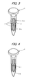
Fig. 2 is a perspective view of a stepped concrete pin according to a modification of the first embodiment. -
Fig. 3 is a perspective view of a stepped concrete pin according to another modification of the first embodiment. -
Fig. 4 is a perspective view of a stepped concrete pin according to yet another modification of the first embodiment. -
Fig. 5 is a perspective view of a stepped concrete pin according to yet another modification of the first embodiment. -
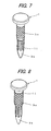
Fig. 6 is a perspective view of a stepped concrete pin according to yet another modification of the first embodiment. -
Fig. 7 is a perspective view of a stepped concrete pin according to yet another modification of the first embodiment. -
Fig. 8 is a perspective view of a stepped concrete pin according to yet another modification of the first embodiment. -
Fig. 9 is a perspective view of a stepped concrete pin according to a second embodiment of the present invention. -
Fig. 10 is a perspective view of a stepped concrete pin according to a modification of the second embodiment. -
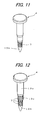
Fig. 11 is a perspective view of a stepped concrete pin according to yet another modification of the second embodiment. -
Fig. 12 is a perspective view of a stepped concrete pin according to yet another modification of the second embodiment. -
Fig. 13 is a perspective view of a stepped concrete pin according to yet another modification of the second embodiment. -
Fig. 14 is a perspective view of a stepped concrete pin according to yet another modification of the second embodiment. -
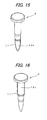
Fig. 15 is a perspective view of a stepped concrete pin according to yet another modification of the second embodiment. -
Fig. 16 is a perspective view of a stepped concrete pin according to yet another modification of the second embodiment. -
- 1, 4
- Stepped Concrete Pin
- 3a, 13a
- Large-Diameter Shaft Part
- 3b, 13b
- Small-Diameter Shaft Part
- 13c
- Intermediate-Diameter Shaft Part
- 7
- Vertical Grooves
- Hereinafter, embodiments of the present invention will be described in detail with reference to the drawings.
-
Fig. 1 is a perspective view of a stepped concrete pin 1 (hereinafter simply referred to as a two-step pin 1) according to a first embodiment of the present invention. - As shown in
Fig. 1 , the two-step pin 1 includes an enlarged-diameter head portion 2 and ashaft portion 3. Theshaft portion 3 includes a large-diameter shaft part 3a (a first shaft part) on a side of the enlargeddiameter head portion 2 and a small-diameter shaft part 3b (a second shaft part) on a side of a tip end. The large-diameter shaft part 3a and the small-diameter shaft part 3b are connected via atapered part 5. Atip end part 6 is formed in a pointed shape. - The small-diameter shaft part 3b has a smaller diameter than a small-diameter shaft part of the conventional two-step pin. A plurality of
vertical grooves 7 are formed on a peripheral face of the small-diameter shaft part 3b. Each of thevertical grooves 7 is continuously formed in the axial direction so as to be parallel to one another. Thevertical groove 7 is not limited to a V-shape but may also be a U-shape. The vertical grooves 7may be formed so as to extend up to a tip end of the small-diameter shaft part 3b. -
Knurl grooves 8 are formed on a peripheral face of the large-diameter shaft part 3a. Theknurl grooves 8 may be formed on the entire large-diameter shaft part 3a. - Striking of the two-
step pin 1 intoconcrete 9 will be described below. - When the two-
step pin 1 is loaded in a nailer and is struck toward theconcrete 9, the tip end of the two-step pin 1 enters into theconcrete 9. At this time, a penetrating resistance is relatively small because the small diameter head portion 3b on the side of the tip end is narrowly formed. Moreover, because thevertical grooves 7 are formed, an area enclosed by a line connecting respective bottoms of thevertical grooves 7 is small. Therefore, the penetrating resistance of the small-diameter shaft part 3b in the initial stage of striking is made even smaller as compared with a case in which thevertical grooves 7 are not provided. Further, because the two-step pin 1 is to be entered in the direction ofvertical grooves 7, a penetrating direction of the two-step pin 1 is stabilized. Accordingly, penetrating performance at the time of striking is enhanced, and the two-step pin 1 can reliably be caused to penetrate in a straight direction without being bent even into an ultra-high hardness concrete. After the striking, because a contact area between thevertical grooves 7 and an inner face of apenetration hole 10 in theconcrete 9 is large, a pulling-out resistance is enhanced. - Further, because the
knurl grooves 8 are formed in the large diameter portion 3a, a surface area of the large-diameter shaft part 3a is large. Accordingly, after the striking, a contact area between the inner face of thepenetration hole 10 in theconcrete 9 and theshaft portion 3 of the two-step pin 1 is remarkably increased. Moreover, because directions of theknurl grooves 8 are different from a pulling-out direction, the resistance to the pulling-out from thepenetration hole 10 in theconcrete 9 is large (i.e., the friction between theknurl grooves 8 and thepenetration hole 10 in theconcrete 9 is large). That is, the holding force is sufficiently ensured, and the pulling-out resistance is remarkably enhanced. In addition, because theknurl grooves 8 do not affect the penetrating direction at the time of striking unlike spiral grooves, the penetrating performance at the time of striking is not deteriorated. - Because the penetrating resistance of the small-diameter shaft part 3b is already small due to it's small diameter, the peripheral face of the small diameter portion 3b may be formed as a smooth surface, as shown in
Fig. 2 . - Means for reinforcing the holding force is not limited to the
knurl grooves 8 formed on the peripheral face of the large-diameter shaft part 3a. For example, as shown inFig. 3 , anagent 11, such as a solid paint or a coating agent, may be applied to an entire peripheral face including the large-diameter shaft part 3a and the small-diameter shaft part 3b. - The
agent 11 reinforces the holding force, and make the two-step pin 1 difficult to be pulled out from the concrete after the penetration. "ThreeBond 2446" (trademark) of aqueous epoxy type produced by precoat bolt MEC process, a product of ThreeBond Co., Ltd., or a bonding agent containing liquid or solid bonding main agent enclosed in micro capsules, a product of Japan Capsular Products, Inc. may be used as theagent 11. - In a case in which the
agent 11 is applied to theshaft portion 3, the penetrating resistance at the time of striking the two-step pin 1 into the concrete is reduced due to a lubricating function of theagent 11. Therefore, the two-step pin 1 can easily penetrate even into the high hardness concrete. Moreover, after the two-step pin 1 has penetrated into the concrete, theagent 11 bonds the two-step pin 1 to the inner face of the penetration hole in the concrete. Therefore, the holding force of the two-step pin 1 can be sufficiently ensured and the pulling-out resistance is remarkably enhanced. - In a modification shown in
Fig. 3 , thevertical grooves 7 are formed in both the large-diameter shaft part 3a and the small-diameter shaft part 3b, and therefore, the penetrating resistance is small. Moreover, the holding force can be reinforced by applying theagent 11. - The
agent 11 need not necessarily be applied to the entire peripheral face of the large-diameter shaft part 3a and the small-diameter shaft part 3b. As shown in Fig. , theagent 11 may be applied only to the small-diameter shaft part 3b. As shown inFig. 5 , theagent 11 may be applied only to the large-diameter shaft part 3a,. - Further, also in a case in which the
knurl grooves 8 are formed on the large-diameter shaft part 3a, theagent 11 may be applied to the entire peripheral face of the large-diameter shaft part 3a and the small-diameter shaft part 3b, as shown inFig. 6 . As shown in Fig. , theagent 11 may be applied only to the small-diameter shaft part 3b. As shown inFig. 8 , theagent 11 may be applied only to the large-diameter shaft part 3a. Moreover, theagent 11 may be applied to the entire small-diameter shaft part 3b and a half of the large-diameter shaft part 3a. -
Fig. 9 is a perspective view of a stepped concrete pin 4 having three steps (hereinafter simply referred to as a three-step pin 4) according to a second embodiment of the present invention. The three-step pin 4 includes an enlargeddiameter head portion 12 and ashaft portion 13. Theshaft portion 13 includes a large-diameter shaft part 13a (a first shaft part) on a side of the enlargeddiameter head portion 2, an intermediate-diameter shaft part 13c (a third shaft part) in an intermediate section, and a small-diameter shaft part 13b (a second shaft part) on a side of a tip end. The large-diameter shaft part 13a, the intermediate-diameter shaft part 13c and the small-diameter shaft part 13b are connected viatapered parts 5. - The small-diameter shaft part 13b is made narrower than a small-diameter shaft part of the conventional two-step pin, whereby the penetrating resistance is reduced. Moreover, because the diameter is gradually increased from the intermediate-diameter shaft part 13c to the large-diameter shaft part 13a, buckling is unlikely to occur. Further, it is possible to increase the holding force, by making the large-diameter shaft part 13a thicker than the large-diameter shaft part 3a of the two-
step pin 1 of the first embodiment. - Because the holding force can be ensured by making the large-diameter shaft part 13a thicker, it is possible to reliably strike the three-step pin 4 even into the ultra-high hardness concrete while reducing the penetrating resistance by forming a plurality of the
vertical grooves 7 in the entire shaft portion, as shown inFig. 10 . Moreover, the penetrating direction can also be stabilized. As shown inFig. 11 , thevertical grooves 7 may be formed only in the small-diameter shaft part 13b. As shown inFig. 12 , thevertical grooves 7 may be formed in the intermediate-diameter shaft part 13c and in the small-diameter shaft part 13b. - As shown in
Fig. 13 , theknurl grooves 8 may be formed in the large-diameter shaft part 13a while forming thevertical grooves 7 in the intermediate shaft portion 13c and in the small-diameter shaft part 13b. In this case, both the reduction of the penetrating resistance and the reinforcement of the holding force can be more effectively obtained. - In order to further reinforce the holding force, for example, the
agent 11 may be applied to the entire peripheral face including the large-diameter shaft part 13a, the intermediate-diameter shaft part 13c, and the small-diameter shaft part 13b, as shown inFig. 14 . In this case, the penetrating resistance at the time of striking the three-step pin 4 into the concrete is reduced due to the lubricating function of theagent 11, and the three-step pin 4 can easily penetrate even into the high hardness concrete. After the three-step pin 4 has penetrated into the concrete, theagent 11 bonds the three-step pin 4 to the inner face of the penetration hole in the concrete. Therefore, the holding force of the three-step pin 4 is sufficiently ensured, and the pulling-out resistance is remarkably enhanced. - The
agent 11 need not necessarily be applied to the entire peripheral surface of the large-diameter shaft part 13a and the small-diameter shaft part 13b. As shown inFig. 15 , theagent 11 may be applied only to the small-diameter shaft part 13b. As shown inFig. 16 , theagent 11 may be applied only to the large-diameter shaft part 13a. Theagent 11 may be applied to the entire small-diameter shaft part 13b and a half of the intermediate-diameter shaft part 13c. - Moreover, the
agent 11 may be applied to the three-step pin 4 which is formed with thevertical grooves 7 or theknurl grooves 8. - While the embodiments of the present invention have been described, it is apparent to those skilled in the art that various changes and modifications can be made therein without departing from the spirit and scope of the invention.
- The present application is based on Japanese Patent Application No.
2006-301661 filed on November 7, 2000 - It is possible to provide a stepped concrete pin having a small penetrating resistance in an initial stage of striking, and also capable of ensuring a holding force.
Claims (10)
- A stepped concrete pin comprising:a head portion; anda shaft portion downwardly extending from a lower face of the head portion,wherein said shaft portion comprises:a first shaft part downwardly extending from the head portion and having a diameter which is constant in a downward direction;a tapered part downwardly extending from a lower end of the first shaft part and having a diameter which gradually decreases in the downward direction;a second shaft part downwardly extending from a lower end of the tapered part and having a diameter which is constant in the downward direction and is narrower than the first shaft part; anda tip end part downwardly extending from a lower end of the second shaft part, and having a diameter which gradually decreases in the downward direction, andwherein knurl grooves are formed in an outer face of the first shaft part.
- The stepped concrete pin according to claim 1, wherein a direction in which the knurl grooves are formed is different from the downward direction.
- The stepped concrete pin according to claim 1, further comprising an adhesive agent which is applied to at least a part of the shaft portion.
- A stepped concrete pin comprising:a head portion;a shaft portion downwardly extending from a lower face of the head portion; andan adhesive agent which is applied to at least a part of the shaft portion,wherein said shaft portion comprises:a first shaft part downwardly extending from the head portion and having a diameter which is constant in a downward direction;a tapered part downwardly extending from a lower end of the first shaft part and having a diameter which gradually decreases in the downward direction;a second shaft part downwardly extending from a lower end of the tapered part and having a diameter which is constant in the downward direction and is narrower than the first shaft part; anda tip end part downwardly extending from a lower end of the second shaft part, and having a diameter which gradually decreases in the downward direction.
- The stepped concrete pin according to claim 4, wherein a plurality of vertical grooves are formed in at least an outer face of the second shaft part.
- A stepped concrete pin comprising:a head portion; anda shaft portion downwardly extending from a lower face of the head portion,wherein said shaft portion comprises:a first shaft part downwardly extending from said head portion and having a diameter which is constant in a downward direction;a first tapered part downwardly extending from a lower end of the first shaft part and having a diameter which gradually decreases in the downward direction;a third shaft part downwardly extending from a lower end of the first tapered part and having a diameter which is constant in the downward direction and is narrower than the first shaft part;a second tapered part downwardly extending from a lower end of the third shaft part and having a diameter which gradually decreases in the downward direction;a second shaft part downwardly extending from a lower end of the second tapered part and having a diameter which is constant in the downward direction and is narrower than the third shaft part; anda tip end part downwardly extending from a lower end of the second shaft part and having a diameter which gradually decreases in the downward direction.
- The stepped concrete pin according to claim 6, wherein a plurality of vertical grooves are formed in at least an outer face of the second shaft part.
- The stepped concrete pin according to claim 6, wherein knurl grooves are formed in an outer face of the first shaft part.
- The stepped concrete pin according to claim 6, wherein a direction in which the knurl grooves are formed is different from the downward direction.
- The stepped concrete pin according to claim 6, further comprising an adhesive agent which is applied to at least a part of the shaft portion.
Applications Claiming Priority (2)
| Application Number | Priority Date | Filing Date | Title |
|---|---|---|---|
| JP2006301661A JP2008115995A (en) | 2006-11-07 | 2006-11-07 | Stepped concrete pin |
| PCT/JP2007/071624 WO2008056695A1 (en) | 2006-11-07 | 2007-11-07 | Stepped concrete pin |
Publications (1)
| Publication Number | Publication Date |
|---|---|
| EP2085624A1 true EP2085624A1 (en) | 2009-08-05 |
Family
ID=39364509
Family Applications (1)
| Application Number | Title | Priority Date | Filing Date |
|---|---|---|---|
| EP07831355A Withdrawn EP2085624A1 (en) | 2006-11-07 | 2007-11-07 | Stepped concrete pin |
Country Status (4)
| Country | Link |
|---|---|
| EP (1) | EP2085624A1 (en) |
| JP (1) | JP2008115995A (en) |
| CN (1) | CN101535662A (en) |
| WO (1) | WO2008056695A1 (en) |
Cited By (3)
| Publication number | Priority date | Publication date | Assignee | Title |
|---|---|---|---|---|
| EP2492520A2 (en) | 2011-02-24 | 2012-08-29 | Max Co., Ltd. | Fastening pin and manufacturing method thereof |
| WO2012159697A1 (en) | 2011-05-24 | 2012-11-29 | Fischerwerke Gmbh & Co. Kg | Fixing element, fixing system and method for setting the fixing element |
| WO2016096107A1 (en) * | 2014-12-20 | 2016-06-23 | Daimler Ag | Connecting element and method for producing a connecting element |
Families Citing this family (5)
| Publication number | Priority date | Publication date | Assignee | Title |
|---|---|---|---|---|
| JP5293472B2 (en) * | 2009-07-15 | 2013-09-18 | マックス株式会社 | Concrete pin |
| JP6013210B2 (en) * | 2013-01-29 | 2016-10-25 | 三星ダイヤモンド工業株式会社 | Scribing wheel pin, holder unit and scribing device |
| CN103272973B (en) * | 2013-06-06 | 2015-11-18 | 李国庆 | A kind of particular manufacturing craft for making small head nail for wall cement slab |
| CN103423269A (en) * | 2013-08-19 | 2013-12-04 | 苏州市胜能弹簧五金制品有限公司 | Wall nail with hot melt adhesive |
| JP6284837B2 (en) * | 2014-06-26 | 2018-02-28 | ライト工業株式会社 | Shear resistance material, its positioning aid, and its installation method |
Family Cites Families (13)
| Publication number | Priority date | Publication date | Assignee | Title |
|---|---|---|---|---|
| JPS57179612U (en) * | 1981-05-11 | 1982-11-13 | ||
| JPS5937410U (en) * | 1982-06-28 | 1984-03-09 | オリン・コ−ポレ−シヨン | fastener |
| JPS6445017U (en) * | 1987-09-15 | 1989-03-17 | ||
| JPH0622608U (en) * | 1992-08-26 | 1994-03-25 | マックス株式会社 | Knurled nails |
| JPH0662218U (en) * | 1993-02-09 | 1994-09-02 | 株式会社ベンリー | Screw nail |
| US6171042B1 (en) * | 1997-12-19 | 2001-01-09 | Illinois Tool Works Inc. | Hardened steel pin, pin and washer fastener, washer for fastener, and pin-making method |
| JP2001105054A (en) * | 1999-10-13 | 2001-04-17 | Citizen Watch Co Ltd | Joining method of metal members |
| JP2002081424A (en) | 2000-09-07 | 2002-03-22 | Sakai Fastening:Kk | Concrete pin and manufacturing method therefor |
| JP4612210B2 (en) * | 2001-03-15 | 2011-01-12 | 株式会社ハーマンプロ | Universal socket |
| JP3878509B2 (en) * | 2002-04-30 | 2007-02-07 | パナホーム株式会社 | Connection structure between main building and shed beam |
| JP2004144121A (en) * | 2002-10-22 | 2004-05-20 | Max Co Ltd | Two-stage grooved concrete pin |
| JP4404541B2 (en) | 2002-11-29 | 2010-01-27 | マックス株式会社 | Concrete pin |
| JP2006264805A (en) * | 2005-03-22 | 2006-10-05 | Konica Minolta Holdings Inc | Adhesive type endless carrying belt or roller, carrying device using the same, and ink jet printer using the same carrying device |
-
2006
- 2006-11-07 JP JP2006301661A patent/JP2008115995A/en active Pending
-
2007
- 2007-11-07 WO PCT/JP2007/071624 patent/WO2008056695A1/en not_active Ceased
- 2007-11-07 CN CNA2007800415370A patent/CN101535662A/en active Pending
- 2007-11-07 EP EP07831355A patent/EP2085624A1/en not_active Withdrawn
Non-Patent Citations (1)
| Title |
|---|
| See references of WO2008056695A1 * |
Cited By (8)
| Publication number | Priority date | Publication date | Assignee | Title |
|---|---|---|---|---|
| EP2492520A2 (en) | 2011-02-24 | 2012-08-29 | Max Co., Ltd. | Fastening pin and manufacturing method thereof |
| CN102650311A (en) * | 2011-02-24 | 2012-08-29 | 美克司株式会社 | Fastening pin and manufacturing method thereof |
| US8794893B2 (en) | 2011-02-24 | 2014-08-05 | Max Co., Ltd. | Fastening pin and manufacturing method thereof |
| CN102650311B (en) * | 2011-02-24 | 2015-05-20 | 美克司株式会社 | Fastening pin and manufacturing method thereof |
| WO2012159697A1 (en) | 2011-05-24 | 2012-11-29 | Fischerwerke Gmbh & Co. Kg | Fixing element, fixing system and method for setting the fixing element |
| DE102011050580A1 (en) | 2011-05-24 | 2012-11-29 | Fischerwerke Gmbh & Co. Kg | Fastening element, fastening system and method for setting the fastening element |
| WO2016096107A1 (en) * | 2014-12-20 | 2016-06-23 | Daimler Ag | Connecting element and method for producing a connecting element |
| US10550874B2 (en) | 2014-12-20 | 2020-02-04 | Daimler Ag | Connection element and method for producing a connection element |
Also Published As
| Publication number | Publication date |
|---|---|
| CN101535662A (en) | 2009-09-16 |
| WO2008056695A1 (en) | 2008-05-15 |
| JP2008115995A (en) | 2008-05-22 |
Similar Documents
| Publication | Publication Date | Title |
|---|---|---|
| JP7143569B2 (en) | Coupling device, related parts and method of use thereof | |
| WO2008056695A1 (en) | Stepped concrete pin | |
| JP5408806B2 (en) | Fastening element | |
| TWI544156B (en) | Fastening pin and manufacturing method thereof | |
| US6862864B2 (en) | Method and apparatus for fastening steel framing members | |
| CA2254250A1 (en) | Hardened steel pin, pin and washer fastener, washer for fastener, and pin-making method | |
| FI100420B (en) | Corrosion-resistant nail for impact on hard materials | |
| TWI292015B (en) | Fastening element | |
| US9458875B2 (en) | Expansion anchor and method for the near-surface anchoring in an anchoring base | |
| WO2004074636A3 (en) | Radially deformed anchorage bolt | |
| KR20060017746A (en) | Metal Piercing Fasteners with Optimal Elastic Fixing Members | |
| JPH04262106A (en) | Anchoring device | |
| US4797046A (en) | Fastening unit with nail anchorage | |
| US20170114814A1 (en) | Thin-Sheet Clinch Fastener | |
| JP5080281B2 (en) | Adhesive anchor, method for constructing adhesive anchor | |
| JP2004144121A (en) | Two-stage grooved concrete pin | |
| CZ280923B6 (en) | Nail with expanding section | |
| WO2007106255A1 (en) | Pin fastener having a sharp point | |
| JP4404541B2 (en) | Concrete pin | |
| JP2006153241A (en) | Drive-in type fastener, connecting fastener and structure | |
| JP2009121662A (en) | Cap for anchor bolt used for repairing wall surface | |
| JP2009184064A (en) | Metal parts breaking method and metal parts breaking device | |
| JP2002122111A (en) | Cushion concrete pin | |
| KR200394408Y1 (en) | Anchor Volt | |
| JP2587567Y2 (en) | Concrete nails |
Legal Events
| Date | Code | Title | Description |
|---|---|---|---|
| PUAI | Public reference made under article 153(3) epc to a published international application that has entered the european phase |
Free format text: ORIGINAL CODE: 0009012 |
|
| 17P | Request for examination filed |
Effective date: 20090427 |
|
| AK | Designated contracting states |
Kind code of ref document: A1 Designated state(s): AT BE BG CH CY CZ DE DK EE ES FI FR GB GR HU IE IS IT LI LT LU LV MC MT NL PL PT RO SE SI SK TR |
|
| DAX | Request for extension of the european patent (deleted) | ||
| STAA | Information on the status of an ep patent application or granted ep patent |
Free format text: STATUS: THE APPLICATION HAS BEEN WITHDRAWN |
|
| 18W | Application withdrawn |
Effective date: 20130729 |