EP2085523A2 - Work vehicle viewing system. - Google Patents
Work vehicle viewing system. Download PDFInfo
- Publication number
- EP2085523A2 EP2085523A2 EP09151695A EP09151695A EP2085523A2 EP 2085523 A2 EP2085523 A2 EP 2085523A2 EP 09151695 A EP09151695 A EP 09151695A EP 09151695 A EP09151695 A EP 09151695A EP 2085523 A2 EP2085523 A2 EP 2085523A2
- Authority
- EP
- European Patent Office
- Prior art keywords
- work vehicle
- window
- brim
- viewing
- cab structure
- Prior art date
- Legal status (The legal status is an assumption and is not a legal conclusion. Google has not performed a legal analysis and makes no representation as to the accuracy of the status listed.)
- Withdrawn
Links
- 238000000034 method Methods 0.000 claims description 5
- 239000000463 material Substances 0.000 description 4
- 229920004142 LEXAN™ Polymers 0.000 description 1
- 230000000712 assembly Effects 0.000 description 1
- 238000000429 assembly Methods 0.000 description 1
- 238000010276 construction Methods 0.000 description 1
- 239000011521 glass Substances 0.000 description 1
- 238000005286 illumination Methods 0.000 description 1
- 230000014759 maintenance of location Effects 0.000 description 1
- 239000002184 metal Substances 0.000 description 1
- 230000003287 optical effect Effects 0.000 description 1
- 239000004033 plastic Substances 0.000 description 1
- 229920000515 polycarbonate Polymers 0.000 description 1
- 239000004417 polycarbonate Substances 0.000 description 1
Images



Classifications
-
- E—FIXED CONSTRUCTIONS
- E02—HYDRAULIC ENGINEERING; FOUNDATIONS; SOIL SHIFTING
- E02F—DREDGING; SOIL-SHIFTING
- E02F9/00—Component parts of dredgers or soil-shifting machines, not restricted to one of the kinds covered by groups E02F3/00 - E02F7/00
- E02F9/16—Cabins, platforms, or the like, for drivers
- E02F9/163—Structures to protect drivers, e.g. cabins, doors for cabins; Falling object protection structure [FOPS]; Roll over protection structure [ROPS]
Definitions
- the present invention relates generally to the field of work vehicles. It relates more particularly to work vehicles having operator cabs.
- the present invention relates to a work vehicle including a frame supporting a cab structure having a brim including a plurality of viewing openings.
- the cab structure includes a window in close proximity to the brim and disposed above an operating viewing position, the window and brim in viewing alignment from the operating viewing position.
- the cab structure is configured to protect the window from vertically falling objects.
- the present invention further relates to a method of providing increased operator visibility for a work vehicle.
- the method includes providing a work vehicle including a frame supporting a cab structure and installing a brim onto the cab structure, the brim including a plurality of viewing openings.
- the method further includes installing a window in the cab structure in close proximity to the brim and disposed above an operating viewing position, the window and brim in viewing alignment from the operating viewing position.
- the cab structure is configured to protect the window from vertically falling objects.
- An advantage of the present invention is increased visibility for an operator of a work vehicle having a cab structure.
- FIGURE 1 shows a work vehicle 10 provided with a frame 12 that rotatably carries a plurality of wheels 14.
- a lifting structure 16 includes an arrangement of structural members and actuators controllable by an operator (not shown) to manipulate an implement 18 to perform work.
- Frame 12 structurally supports a cab structure 20 to surround and protect the operator, which frame 12 includes a front end 24 facing implement 18, with front end 24 disposed between opposed sides 26, 27.
- cab structure 20 includes a brim 22 protruding toward end 24, although in an alternate embodiment, brim 22 or additional brims 22 may extend toward opposed sides 26, 27 or toward the end opposite end 24.
- a pair of light assemblies 28 is secured in proximity to opposed sides 26, 27 and also proximate to end 24.
- Each light assembly 28 provides additional illumination of the surrounding region exterior of work vehicle 10, permitting an operator (not shown) to more safely operate work vehicle 10.
- a window 30 FIGURE 2
- brim 22 provides a viewing system in viewing alignment from an operating viewing position 54 ( FIGURE 4 ) to further enhance operating safety.
- operating viewing position 54 is intended to refer to a viewing vantage point of an operator while operating a work vehicle.
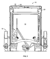
- FIGURE 2 which is taken along line 2-2 of FIGURE 1 , provides a forward-looking viewing vantage point from interior of the cab structure 20 of work vehicle 10. It is appreciated by those having ordinary skill in the art that inclusion of window 30 provides the operator (not shown) with enhanced viewing, such as the ability to view implement 18 ( FIGURE 1 ) when implement 18 is raised to its highest position.
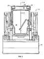
- FIGURE 3 which is a front view, shows window 30 and the substantially increased viewing area made available to the operator.
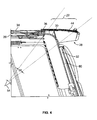
- FIGURE 4 which is an enlarged partial cross-sectional view taken along line 4-4 of FIGURE 3 , shows operating viewing position 54, as well as a viewing range 56 made possible by window 30. It is apparent from FIGURE 4 that viewing openings 44, better shown in FIGURE 7 , provide virtually unobstructed viewing through brim 22. In one embodiment, viewing openings 44 are arranged to form a lattice.
- window 30 includes a frame 38 having corresponding slots or openings 58 for receiving fasteners 40 to secure window 30 to cab structure 20 ( FIGURE 4 ).
- a wall 60 is disposed below window 30.
- wall 60 includes a door 32 pivotably connected to cab structure 20 ( FIGURE 3 ). In this position, window 30 is disposed along a junction between a roof 34 and wall 60 of the cab structure 20. In a further embodiment, window 30 is curved.
- Window 30 is composed of a suitable material having enhanced optical qualities while minimizing distortion associated with curvature, such as Lexan®, a registered trademark of General Electric Company, polycarbonate, plastic, glass, metal screen or other suitable material.
- window 30 is constructed of a material that polarizes light passing therethrough.
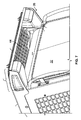
- a cover 36 overlies brim 22 to permit passage of light therethrough, and additionally through viewing openings 44 ( FIGURE 7 ) formed in brim 22.
- cover 36 is contiguous and substantially transparent.
- cover 36 is constructed of a material that polarizes light passing therethrough.
- brim 22 includes a pair of outwardly extending studs 46 (only one shown in FIGURE 6 ), with each stud 46 received by an opening 48 formed in cover 36.
- a fastener such as a pin fastener 50 having a pivoting locking ring 52, commonly referred to as a lynch pin of known construction may be used.
- cover 36 overlies a substantial portion of brim 22, and in an alternate embodiment, overlies brim 22 virtually in its entirety.
- cover 36 includes a border 42 disposed along the perimeter of the cover. Cover 36 helps protect window 30 from vertically falling objects that are sufficiently small to fall through the viewing openings 44 ( FIGURE 7 ) formed in brim 22.
- a retrofit kit may be provided for a work vehicle to add a brim 22 having viewing openings 44, cover 36 and window 30, as shown in the FIGURES 1 , 6 , 7 and described above.
Landscapes
- Engineering & Computer Science (AREA)
- Mining & Mineral Resources (AREA)
- Civil Engineering (AREA)
- General Engineering & Computer Science (AREA)
- Structural Engineering (AREA)
- Window Of Vehicle (AREA)
- Body Structure For Vehicles (AREA)
- Component Parts Of Construction Machinery (AREA)
Abstract
Description
- The present invention relates generally to the field of work vehicles. It relates more particularly to work vehicles having operator cabs.
- The present invention relates to a work vehicle including a frame supporting a cab structure having a brim including a plurality of viewing openings. The cab structure includes a window in close proximity to the brim and disposed above an operating viewing position, the window and brim in viewing alignment from the operating viewing position. The cab structure is configured to protect the window from vertically falling objects.
- The present invention further relates to a method of providing increased operator visibility for a work vehicle. The method includes providing a work vehicle including a frame supporting a cab structure and installing a brim onto the cab structure, the brim including a plurality of viewing openings. The method further includes installing a window in the cab structure in close proximity to the brim and disposed above an operating viewing position, the window and brim in viewing alignment from the operating viewing position. The cab structure is configured to protect the window from vertically falling objects.
- An advantage of the present invention is increased visibility for an operator of a work vehicle having a cab structure.
- Other features and advantages of the present invention will be apparent from the following more detailed description of the preferred embodiment, taken in conjunction with the accompanying drawings which illustrate, by way of example, the principles of the invention.
-
-
FIGURE 1 is a top perspective view of an embodiment of a work vehicle of the present invention; -
FIGURE 2 is an enlarged, partial cross-section taken along line 2-2 ofFIGURE 1 of the present invention; -
FIGURE 3 is a front view of an embodiment of a work vehicle of the present invention; -
FIGURE 4 is an enlarged, partial cross-section taken along line 4-4 ofFIGURE 3 of the present invention; -
FIGURE 5 is a top perspective view of an embodiment of a door and window of the present invention; -
FIGURE 6 is an enlarged partial top perspective view of an upper portion of an embodiment of a work vehicle cab structure of the present invention: -
FIGURE 7 is an enlarged partial bottom perspective view of an upper portion of an embodiment of a work vehicle cab structure of the present invention. - In the drawings, like reference numerals refer to like parts throughout the several views.
-
FIGURE 1 shows awork vehicle 10 provided with aframe 12 that rotatably carries a plurality ofwheels 14. Alifting structure 16 includes an arrangement of structural members and actuators controllable by an operator (not shown) to manipulate animplement 18 to perform work.Frame 12 structurally supports acab structure 20 to surround and protect the operator, whichframe 12 includes afront end 24 facingimplement 18, withfront end 24 disposed betweenopposed sides FIGURE 1 ,cab structure 20 includes abrim 22 protruding towardend 24, although in an alternate embodiment,brim 22 oradditional brims 22 may extend towardopposed sides opposite end 24. In one embodiment, a pair oflight assemblies 28 is secured in proximity toopposed sides light assembly 28 provides additional illumination of the surrounding region exterior ofwork vehicle 10, permitting an operator (not shown) to more safely operatework vehicle 10. As will be discussed in further detail below, a window 30 (FIGURE 2 ) in combination withbrim 22 provides a viewing system in viewing alignment from an operating viewing position 54 (FIGURE 4 ) to further enhance operating safety. For purposes herein, operatingviewing position 54 is intended to refer to a viewing vantage point of an operator while operating a work vehicle. -
FIGURE 2 , which is taken along line 2-2 ofFIGURE 1 , provides a forward-looking viewing vantage point from interior of thecab structure 20 ofwork vehicle 10. It is appreciated by those having ordinary skill in the art that inclusion ofwindow 30 provides the operator (not shown) with enhanced viewing, such as the ability to view implement 18 (FIGURE 1 ) whenimplement 18 is raised to its highest position.FIGURE 3 , which is a front view, showswindow 30 and the substantially increased viewing area made available to the operator.FIGURE 4 , which is an enlarged partial cross-sectional view taken along line 4-4 ofFIGURE 3 , showsoperating viewing position 54, as well as aviewing range 56 made possible bywindow 30. It is apparent fromFIGURE 4 thatviewing openings 44, better shown inFIGURE 7 , provide virtually unobstructed viewing throughbrim 22. In one embodiment,viewing openings 44 are arranged to form a lattice. - As shown in
FIGURE 5 , one embodiment ofwindow 30 includes aframe 38 having corresponding slots oropenings 58 for receivingfasteners 40 to securewindow 30 to cab structure 20 (FIGURE 4 ). In one embodiment, as shown inFIGURE 4 , awall 60 is disposed belowwindow 30. As further shown inFIGURE 4 ,wall 60 includes adoor 32 pivotably connected to cab structure 20 (FIGURE 3 ). In this position,window 30 is disposed along a junction between aroof 34 andwall 60 of thecab structure 20. In a further embodiment,window 30 is curved.Window 30 is composed of a suitable material having enhanced optical qualities while minimizing distortion associated with curvature, such as Lexan®, a registered trademark of General Electric Company, polycarbonate, plastic, glass, metal screen or other suitable material. In one embodiment,window 30 is constructed of a material that polarizes light passing therethrough. - As shown in
FIGURES 1 and6 , acover 36 overliesbrim 22 to permit passage of light therethrough, and additionally through viewing openings 44 (FIGURE 7 ) formed inbrim 22. In one embodiment,cover 36 is contiguous and substantially transparent. In another embodiment,cover 36 is constructed of a material that polarizes light passing therethrough. In one embodiment,brim 22 includes a pair of outwardly extending studs 46 (only one shown inFIGURE 6 ), with each stud 46 received by an opening 48 formed incover 36. A fastener, such as a pin fastener 50 having a pivoting locking ring 52, commonly referred to as a lynch pin of known construction may be used. In an alternate embodiment, threaded fasteners or fasteners with other retention features many be used. As further shown inFIGURES 1 and6 ,cover 36 overlies a substantial portion ofbrim 22, and in an alternate embodiment, overliesbrim 22 virtually in its entirety. In one embodiment,cover 36 includes a border 42 disposed along the perimeter of the cover.Cover 36 helps protectwindow 30 from vertically falling objects that are sufficiently small to fall through the viewing openings 44 (FIGURE 7 ) formed inbrim 22. - It is contemplated that a retrofit kit may be provided for a work vehicle to add a
brim 22 havingviewing openings 44,cover 36 andwindow 30, as shown in theFIGURES 1 ,6 ,7 and described above.
Claims (11)
- A work vehicle (10) comprising:a frame (12) supporting a cab structure (20) having a brim (22) including a plurality of viewing openings (44);said cab structure (20) including a window (30) in close proximity to said brim (22) and disposed above an operating viewing position (54), said window (30) and brim (22) in viewing alignment from said operating viewing position (54); andcharacterized in that said cab structure (20) is configured to protect said window (30) from vertically falling objects.
- A work vehicle according to claim 1, wherein said window (30) is disposed along a junction between a roof (34) and a wall (60) of said cab structure (20).
- A work vehicle according to claims 1 or 2, wherein said window (30) is curved.
- A work vehicle according to claims 2 or 3, characterized in that said wall (60) includes a pivotably connected door (32).
- A work vehicle according to claim 4, characterized in that said door (32) is disposed below said window (30).
- A work vehicle according to any of the preceding claims, characterized in that said viewing openings (44) form a lattice.
- A work vehicle according to any of the preceding claims, characterized in that said viewing openings (44) are overlain by a contiguous cover (36).
- A work vehicle according to claim 7, characterized in that said cover (36) permits passage of light therethrough.
- A work vehicle according to claim 8, characterized in that said cover (36) is substantially transparent.
- A work vehicle according to claim 8, characterized in that said cover (36) polarizes light passing therethrough.
- A method of providing increased operator visibility for a work vehicle 10, characterized in that said method comprises the steps of:providing a work vehicle (10) including a frame (12) supporting a cab structure (20);installing a brim (22) onto said cab structure (20), said brim (22) including a plurality of viewing openings (44); andinstalling a window (30) in said cab structure (20) in close proximity to said brim (22) and disposed above an operating viewing position (54), said window (30) and brim (22) in viewing alignment from the operating viewing position (54), wherein said cab structure (20) is configured to protect said window (30) from vertically falling objects.
Applications Claiming Priority (1)
| Application Number | Priority Date | Filing Date | Title |
|---|---|---|---|
| US12/023,278 US7731273B2 (en) | 2008-01-31 | 2008-01-31 | Work vehicle viewing system |
Publications (2)
| Publication Number | Publication Date |
|---|---|
| EP2085523A2 true EP2085523A2 (en) | 2009-08-05 |
| EP2085523A3 EP2085523A3 (en) | 2017-04-19 |
Family
ID=40451151
Family Applications (1)
| Application Number | Title | Priority Date | Filing Date |
|---|---|---|---|
| EP09151695.5A Withdrawn EP2085523A3 (en) | 2008-01-31 | 2009-01-30 | Work vehicle viewing system. |
Country Status (2)
| Country | Link |
|---|---|
| US (1) | US7731273B2 (en) |
| EP (1) | EP2085523A3 (en) |
Cited By (1)
| Publication number | Priority date | Publication date | Assignee | Title |
|---|---|---|---|---|
| EP2772376A1 (en) * | 2013-02-27 | 2014-09-03 | Vitalo Industries NV | Body panel and roof of a vehicle cabin formed by or comprising such a body panel. |
Families Citing this family (9)
| Publication number | Priority date | Publication date | Assignee | Title |
|---|---|---|---|---|
| JP4467595B2 (en) * | 2007-03-28 | 2010-05-26 | 株式会社クボタ | Work vehicle canopy equipment |
| US7874999B2 (en) * | 2007-09-24 | 2011-01-25 | Baxter International, Inc. | Detecting access disconnect using needle sleeve |
| DE202012003669U1 (en) * | 2012-04-12 | 2013-07-15 | Joseph Vögele AG | Driver roof for operator station of a road construction machine |
| US10030362B2 (en) * | 2014-09-30 | 2018-07-24 | Kubota Corporation | Cabin of working machine, working machine having cabin, and method for manufacturing cabin |
| US20150345210A1 (en) * | 2015-08-14 | 2015-12-03 | Caterpillar Inc. | Panel assembly for door member of machine |
| WO2018195311A1 (en) | 2017-04-19 | 2018-10-25 | Clark Equipment Company | Loader cab |
| KR101879157B1 (en) * | 2018-03-29 | 2018-08-16 | 김학성 | Doors and window frames for forklift cabins mounted without drilling |
| US12077938B2 (en) * | 2021-10-12 | 2024-09-03 | Caterpillar Inc. | Secondary control system and method for mounting with service orientation |
| JP2024031360A (en) * | 2022-08-26 | 2024-03-07 | プレス工業株式会社 | construction machinery cabin |
Family Cites Families (33)
| Publication number | Priority date | Publication date | Assignee | Title |
|---|---|---|---|---|
| US3336074A (en) | 1965-12-03 | 1967-08-15 | Clark Equipment Co | Collapsible overhead guard for industrial lift truck |
| US3690720A (en) * | 1970-07-27 | 1972-09-12 | Deere & Co | Vehicle cab and safety frame assembly |
| US4119340A (en) * | 1977-08-01 | 1978-10-10 | Harnischfeger Corporation | Roof window for crane operator's cab |
| US4679847A (en) | 1986-07-01 | 1987-07-14 | Dirck Ronald L | Removable cab top for vehicles |
| JPH02216375A (en) | 1989-02-17 | 1990-08-29 | Kubota Ltd | Cabin for tractor |
| JPH0370686A (en) | 1989-08-09 | 1991-03-26 | Iseki & Co Ltd | Cabin roof of tractor or the like |
| AU7280896A (en) * | 1995-11-02 | 1997-05-22 | Bosal-Sekura Industries A/S | Drivers cab for working vehicles comprising openable front- and rear window |
| JPH11280116A (en) * | 1998-03-31 | 1999-10-12 | Takahashi Works:Kk | Driver cab protection |
| CN1098954C (en) * | 1998-05-26 | 2003-01-15 | 日立建机株式会社 | Cab for construction machinery |
| USD427612S (en) * | 1998-12-31 | 2000-07-04 | Daewoo Heavy Industries Ltd. | Forklift truck cabin |
| USD438878S1 (en) * | 1999-05-05 | 2001-03-13 | Caterpillar Inc. | Cab structure for a forestry swing machine |
| JP4386307B2 (en) | 2000-02-23 | 2009-12-16 | 株式会社小松製作所 | Construction machinery |
| US6220656B1 (en) | 2000-03-23 | 2001-04-24 | Martin Sheet Metal, Inc. | Cab with improved overhead vision |
| JP3747733B2 (en) * | 2000-03-28 | 2006-02-22 | 日立建機株式会社 | Construction machine cab |
| US6561572B1 (en) | 2001-01-31 | 2003-05-13 | Martin Sheet Metal, Inc. | Cab enclosure construction |
| USD463807S1 (en) * | 2001-04-19 | 2002-10-01 | Komatsu Ltd. | Operator cabin of power shovel |
| JP3717428B2 (en) | 2001-07-19 | 2005-11-16 | 株式会社クボタ | Tractor with cabin |
| US6688682B2 (en) * | 2001-08-29 | 2004-02-10 | Deere & Co. | Window panel and roof visor system for a utility vehicle |
| USD471213S1 (en) | 2002-01-25 | 2003-03-04 | Volvo Construction Equipment Holding Sweden Ab | Excavator cab |
| USD494986S1 (en) | 2002-09-26 | 2004-08-24 | Clark Equipment Company | Mini-excavator cab exterior |
| JP4201126B2 (en) * | 2003-04-10 | 2008-12-24 | 株式会社小松製作所 | Construction machinery cab |
| US20050012360A1 (en) * | 2003-07-14 | 2005-01-20 | Clark Equipment Company | Work vehicle cab screen |
| US7290829B2 (en) * | 2004-06-29 | 2007-11-06 | Kubota Corporation | Working vehicle with a cab |
| USD523875S1 (en) * | 2005-01-28 | 2006-06-27 | Volvo Construction Equipment Holding Sweden Ab | Excavator cabin |
| JP4670436B2 (en) * | 2005-03-31 | 2011-04-13 | 株式会社豊田自動織機 | Industrial vehicle head guard |
| KR100689292B1 (en) | 2005-06-01 | 2007-03-02 | 볼보 컨스트럭션 이키프먼트 홀딩 스웨덴 에이비 | Operator protection structure mounted in heavy equipment cab |
| JP4504283B2 (en) * | 2005-08-30 | 2010-07-14 | 日立建機株式会社 | Construction machinery |
| US20070145780A1 (en) * | 2005-12-23 | 2007-06-28 | Caterpillar Inc. | Rotatable cab with multi-piece deck |
| USD544889S1 (en) | 2006-03-06 | 2007-06-19 | Cnh America Llc | High visibility roof for tractor cab |
| USD549742S1 (en) * | 2006-10-25 | 2007-08-28 | Adc Global Inc. | Rollover protection structure |
| USD577040S1 (en) * | 2007-04-16 | 2008-09-16 | Volvo Construction Equipment Holding Sweden Ab | Cabin for heavy construction equipment |
| US7677647B2 (en) * | 2008-01-31 | 2010-03-16 | Cnh America Llc | Adjustable mounting restraint device |
| USD607904S1 (en) * | 2009-05-08 | 2010-01-12 | Clark Equipment Company | Excavator cab exterior |
-
2008
- 2008-01-31 US US12/023,278 patent/US7731273B2/en active Active
-
2009
- 2009-01-30 EP EP09151695.5A patent/EP2085523A3/en not_active Withdrawn
Cited By (1)
| Publication number | Priority date | Publication date | Assignee | Title |
|---|---|---|---|---|
| EP2772376A1 (en) * | 2013-02-27 | 2014-09-03 | Vitalo Industries NV | Body panel and roof of a vehicle cabin formed by or comprising such a body panel. |
Also Published As
| Publication number | Publication date |
|---|---|
| US20090195021A1 (en) | 2009-08-06 |
| EP2085523A3 (en) | 2017-04-19 |
| US7731273B2 (en) | 2010-06-08 |
Similar Documents
| Publication | Publication Date | Title |
|---|---|---|
| US7731273B2 (en) | Work vehicle viewing system | |
| KR20170001069U (en) | Mothproof apparatus for vehicle | |
| EP1803594B1 (en) | Door construction for vehicle | |
| US6276750B1 (en) | Fork lift truck cab | |
| CN102164763A (en) | Automobile roof structure | |
| US9487132B2 (en) | Vehicle warning lighting system | |
| JP7021221B2 (en) | Automotive structure with sunroof, roof frame, and corresponding roof | |
| ITTO20100036A1 (en) | COVER SET OF A CABIN OF A TRACTOR | |
| US10773577B2 (en) | Vehicle rear door made of resin | |
| US9327772B2 (en) | Cabin device of working machine | |
| US6328370B1 (en) | Horizontally and vertically positionable sun visor | |
| US4836599A (en) | Vehicle visor installation | |
| US20090196057A1 (en) | Side Lights For Work Vehicles | |
| JP2004114850A (en) | Outside lighting system for work machine | |
| CN206254749U (en) | sunshade fixing assembly | |
| US20150354927A1 (en) | Armoured vehicle body shell with smaller struts | |
| EP2746080B1 (en) | A roof panel | |
| JP5359893B2 (en) | Tailgate panel reinforcement structure | |
| EP2143579B1 (en) | Moveable structural crosspiece for the roof of an automobile vehicle with panoramic windscreen | |
| JP7240795B2 (en) | vehicle front structure | |
| JP3546872B2 (en) | Cabin of moving vehicle | |
| JP2008308040A (en) | Vehicular door device | |
| JP2024172216A (en) | Vehicle-mounted camera installation structure | |
| JPH026219A (en) | Door of automobile | |
| JP2004322980A (en) | Driver's cab for construction machinery |
Legal Events
| Date | Code | Title | Description |
|---|---|---|---|
| PUAI | Public reference made under article 153(3) epc to a published international application that has entered the european phase |
Free format text: ORIGINAL CODE: 0009012 |
|
| AK | Designated contracting states |
Kind code of ref document: A2 Designated state(s): AT BE BG CH CY CZ DE DK EE ES FI FR GB GR HR HU IE IS IT LI LT LU LV MC MK MT NL NO PL PT RO SE SI SK TR |
|
| AX | Request for extension of the european patent |
Extension state: AL BA RS |
|
| RAP1 | Party data changed (applicant data changed or rights of an application transferred) |
Owner name: CNH ITALIA S.P.A. |
|
| RAP1 | Party data changed (applicant data changed or rights of an application transferred) |
Owner name: CNH ITALIA S.P.A. |
|
| RAP1 | Party data changed (applicant data changed or rights of an application transferred) |
Owner name: CNH INDUSTRIAL ITALIA S.P.A. |
|
| PUAL | Search report despatched |
Free format text: ORIGINAL CODE: 0009013 |
|
| AK | Designated contracting states |
Kind code of ref document: A3 Designated state(s): AT BE BG CH CY CZ DE DK EE ES FI FR GB GR HR HU IE IS IT LI LT LU LV MC MK MT NL NO PL PT RO SE SI SK TR |
|
| AX | Request for extension of the european patent |
Extension state: AL BA RS |
|
| RIC1 | Information provided on ipc code assigned before grant |
Ipc: E02F 9/16 20060101AFI20170313BHEP |
|
| STAA | Information on the status of an ep patent application or granted ep patent |
Free format text: STATUS: REQUEST FOR EXAMINATION WAS MADE |
|
| 17P | Request for examination filed |
Effective date: 20171019 |
|
| RBV | Designated contracting states (corrected) |
Designated state(s): AT BE BG CH CY CZ DE DK EE ES FI FR GB GR HR HU IE IS IT LI LT LU LV MC MK MT NL NO PL PT RO SE SI SK TR |
|
| AKX | Designation fees paid |
Designated state(s): AT BE BG CH CY CZ DE DK EE ES FI FR GB GR HR HU IE IS IT LI LT LU LV MC MK MT NL NO PL PT RO SE SI SK TR |
|
| AXX | Extension fees paid |
Extension state: AL Extension state: RS Extension state: BA |
|
| STAA | Information on the status of an ep patent application or granted ep patent |
Free format text: STATUS: THE APPLICATION IS DEEMED TO BE WITHDRAWN |
|
| 18D | Application deemed to be withdrawn |
Effective date: 20171020 |