EP2085303A2 - Accessory connecting means for bicycle saddle - Google Patents
Accessory connecting means for bicycle saddle Download PDFInfo
- Publication number
- EP2085303A2 EP2085303A2 EP08010715A EP08010715A EP2085303A2 EP 2085303 A2 EP2085303 A2 EP 2085303A2 EP 08010715 A EP08010715 A EP 08010715A EP 08010715 A EP08010715 A EP 08010715A EP 2085303 A2 EP2085303 A2 EP 2085303A2
- Authority
- EP
- European Patent Office
- Prior art keywords
- engaging portion
- connecting means
- chamber
- pair
- engaging
- Prior art date
- Legal status (The legal status is an assumption and is not a legal conclusion. Google has not performed a legal analysis and makes no representation as to the accuracy of the status listed.)
- Granted
Links
- 230000008878 coupling Effects 0.000 claims abstract description 13
- 238000010168 coupling process Methods 0.000 claims abstract description 13
- 238000005859 coupling reaction Methods 0.000 claims abstract description 13
- 230000037431 insertion Effects 0.000 claims description 2
- 238000003780 insertion Methods 0.000 claims description 2
- 230000005484 gravity Effects 0.000 description 1
- 238000010338 mechanical breakdown Methods 0.000 description 1
- XLYOFNOQVPJJNP-UHFFFAOYSA-N water Substances O XLYOFNOQVPJJNP-UHFFFAOYSA-N 0.000 description 1
Images

Classifications
-
- B—PERFORMING OPERATIONS; TRANSPORTING
- B62—LAND VEHICLES FOR TRAVELLING OTHERWISE THAN ON RAILS
- B62J—CYCLE SADDLES OR SEATS; AUXILIARY DEVICES OR ACCESSORIES SPECIALLY ADAPTED TO CYCLES AND NOT OTHERWISE PROVIDED FOR, e.g. ARTICLE CARRIERS OR CYCLE PROTECTORS
- B62J9/00—Containers specially adapted for cycles, e.g. panniers or saddle bags
- B62J9/20—Containers specially adapted for cycles, e.g. panniers or saddle bags attached to the cycle as accessories
- B62J9/26—Containers specially adapted for cycles, e.g. panniers or saddle bags attached to the cycle as accessories to the saddle, e.g. saddle bags
-
- Y—GENERAL TAGGING OF NEW TECHNOLOGICAL DEVELOPMENTS; GENERAL TAGGING OF CROSS-SECTIONAL TECHNOLOGIES SPANNING OVER SEVERAL SECTIONS OF THE IPC; TECHNICAL SUBJECTS COVERED BY FORMER USPC CROSS-REFERENCE ART COLLECTIONS [XRACs] AND DIGESTS
- Y10—TECHNICAL SUBJECTS COVERED BY FORMER USPC
- Y10T—TECHNICAL SUBJECTS COVERED BY FORMER US CLASSIFICATION
- Y10T24/00—Buckles, buttons, clasps, etc.
- Y10T24/45—Separable-fastener or required component thereof [e.g., projection and cavity to complete interlock]
- Y10T24/45005—Separable-fastener or required component thereof [e.g., projection and cavity to complete interlock] with third detached member completing interlock [e.g., hook type]
- Y10T24/45099—Resilient element [e.g., snap type]
-
- Y—GENERAL TAGGING OF NEW TECHNOLOGICAL DEVELOPMENTS; GENERAL TAGGING OF CROSS-SECTIONAL TECHNOLOGIES SPANNING OVER SEVERAL SECTIONS OF THE IPC; TECHNICAL SUBJECTS COVERED BY FORMER USPC CROSS-REFERENCE ART COLLECTIONS [XRACs] AND DIGESTS
- Y10—TECHNICAL SUBJECTS COVERED BY FORMER USPC
- Y10T—TECHNICAL SUBJECTS COVERED BY FORMER US CLASSIFICATION
- Y10T24/00—Buckles, buttons, clasps, etc.
- Y10T24/45—Separable-fastener or required component thereof [e.g., projection and cavity to complete interlock]
- Y10T24/45225—Separable-fastener or required component thereof [e.g., projection and cavity to complete interlock] including member having distinct formations and mating member selectively interlocking therewith
- Y10T24/45471—Projection having movable connection between components thereof or variable configuration
- Y10T24/45524—Projection having movable connection between components thereof or variable configuration including resiliently biased projection component or surface segment
- Y10T24/45529—Requiring manual force applied against bias to interlock or disengage
- Y10T24/45534—Requiring manual force applied against bias to interlock or disengage having connected leading edge and separated trailing arms
-
- Y—GENERAL TAGGING OF NEW TECHNOLOGICAL DEVELOPMENTS; GENERAL TAGGING OF CROSS-SECTIONAL TECHNOLOGIES SPANNING OVER SEVERAL SECTIONS OF THE IPC; TECHNICAL SUBJECTS COVERED BY FORMER USPC CROSS-REFERENCE ART COLLECTIONS [XRACs] AND DIGESTS
- Y10—TECHNICAL SUBJECTS COVERED BY FORMER USPC
- Y10T—TECHNICAL SUBJECTS COVERED BY FORMER US CLASSIFICATION
- Y10T24/00—Buckles, buttons, clasps, etc.
- Y10T24/45—Separable-fastener or required component thereof [e.g., projection and cavity to complete interlock]
- Y10T24/45225—Separable-fastener or required component thereof [e.g., projection and cavity to complete interlock] including member having distinct formations and mating member selectively interlocking therewith
- Y10T24/4588—Means for mounting projection or cavity portion
- Y10T24/45942—Means for mounting projection or cavity portion having threaded formation
Definitions
- the present invention relates generally to bicycle saddles, more particularly, to a connecting means for connecting containers or accessories to a bicycle saddle.
- U.S. Pat. No. 5,593,126 discloses a quick-connect structure for a bicycle saddle that allows an easy and safe connection of accessories to the bicycle saddle.
- the quick-connect structure has one male member that may be snap-fitted in a corresponding female member.
- the male and female members are separately associated to the saddle and an object for attachment to the saddle.
- the primary drawback of the structure is that the accessory coupled thereto may loosen or fail with time because the direction of the external force to release the male member from the female member is the same as that of the force that gravity applies to the accessory.
- the primary objective of this invention is to overcome the above drawback by providing an improved accessory connecting means which allows an easy, quick and safe connection of accessories to a bicycle saddle.
- an accessory connecting means for a bicycle saddle comprises a first connecting member, a second connecting member and a latching apparatus.
- the first connecting member is fixed to a bicycle saddle and can releasably engage with the second connecting member which is coupled with an accessory.
- the first connecting member includes a fixing portion, and a first engaging portion.
- the fixing portion has an upper side to be fixed to the bicycle saddle.
- the first engaging portion extends downward from a lower side of the fixing portion.
- the second connecting member includes a coupling portion and a second engaging portion.
- the coupling portion has a lower side to removably be coupled with the accessory.
- the second engaging portion extends upwardly from an upper side of the coupling portion to releasably engage with the first engaging portion of the first connecting member.
- the latching apparatus is disposed between the first and second engaging portions in such a way that the first and second engaging portions can be interlocked with each other at the time of engagement and quickly released from each other at the time of disengagement.
- an accessory connecting means constructed in accordance with the present invention is generally designated as numeral 10.
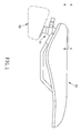
- the connecting means 10 is suitable for removably connecting an accessory 80, such as a tool kit, a mudguard, a reflector, a water bottle cage, or the like, to a bicycle saddle 90, as shown in FIG. 1 .
- the connecting means 10 includes a first connecting member 12 and a second connecting member 14. They can be plastic molded devices.
- the first connecting member 12 has a fixing portion 20, an extending post 22 and a first engaging portion 24.
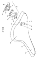
- the second connecting member 14 has a coupling portion 30, a guiding portion 32 and a second engaging portion 34, as shown in FIG. 2 .
- the fixing portion 20 has a triangularly shaped board 201 with a pair of projections 204 extending from a side 202 thereof and a threaded hole 206 disposed on a vertex 203 of the board 201 opposite the side 202.
- the bicycle saddle 90 as shown in FIG. 2 , includes a body frame 92 having a narrow front end 94 and a wide rear end 96.
- the wide rear end 96 of the frame 92 has a recess 95 with a through hole 97 and a pair of open nests 98.
- each of the projections 204 of the board 201 is inserted into one of the open nests 98 of the frame 92, and then a bolt 70 passes through the hole 97and engages with the threaded hole 206 of the board 201 so that the first connecting member 12 is fixed to the frame 92 of the bicycle saddle 90.
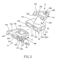
- the extending post 22 of the first connecting member 12 extends downward a predetermined length from the under surface of the fixing portion 20 and connects with the first engaging portion 24.
- the first engaging portion 24 includes a top wall 242 connected to the free end of the post 22, a bottom wall 244 and a pair of opposing side walls 246, 248 connecting the top and bottom walls 242, 244.
- the side walls 246, 248 and the top and bottom walls 242, 244 define a chamber 250 therebetween which is open at an open end thereof.
- the bottom wall 244 has an open guiding channel 252 and a stopping wall 254 formed on the rear end of the channel 252.
- Each of the side walls 246, 248 has an aperture 256, 258.
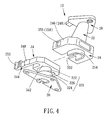
- the coupling portion 30 of the second connecting member 14 is a triangularly shaped board coupled with the accessory 80.
- the guiding portion 32 extends upwardly a predetermined length from the upper surface of the coupling portion 30.
- the guiding portion 32 has an upper area 322, a lower area 324 and a step area 326 formed therebetween.
- the second engaging portion 34 includes a base 342 connected to the free end of the guiding portion 32, a pair of resiliently flexible arms 344, 346 extending along opposite sides of the base 342.
- Each of the arms 344, 346 has a latching protrusion 348, 350 and a pressing end 352, 354.
- the pressing ends 352, 354 of the arms 344, 346 are first pressed inward toward the base 342 so that the second engaging portion 34 is inserted within the chamber 250 of the first engaging portion 24 by the guide of the guiding portion 32 passing through the channel 252. Further insertion of the second engaging portion 34 will result in the latching protrusion 348, 350 moving into the apertures 256, 258, at which point each arm 344, 346 snaps outward with respect to the chamber 250.
- each latching protrusion 348, 350 extends out respectively from the side walls 246, 248 of the first engaging portion 24 through each of apertures 256, 258 so that the first engaging portion 24 and the second engaging portion 34 are interlocked with each other, as shown in FIG. 5 .
- a user exerts inward force against the pressing ends 352, 354 to flex the arms 344, 346 inward with respect to the chamber 250 to clear the latching protrusions 348, 350 from the apertures 256, 258.
- the latching protrusions 348, 350 move away from the apertures 256, 258, the second engaging portion 34 can be removed from the first engaging portion 24.
Abstract
Description
- The present invention relates generally to bicycle saddles, more particularly, to a connecting means for connecting containers or accessories to a bicycle saddle.
- When riding a bicycle, it is necessary to have equipment to carry emergency tool and accessories to be used in case of mechanical breakdowns. Special containers or tool kits have been designed to this purpose and a number of technical arrangements have been developed to solve the problem of carrying such containers.
-
U.S. Pat. No. 5,593,126 discloses a quick-connect structure for a bicycle saddle that allows an easy and safe connection of accessories to the bicycle saddle. The quick-connect structure has one male member that may be snap-fitted in a corresponding female member. The male and female members are separately associated to the saddle and an object for attachment to the saddle. The primary drawback of the structure is that the accessory coupled thereto may loosen or fail with time because the direction of the external force to release the male member from the female member is the same as that of the force that gravity applies to the accessory. - The primary objective of this invention is to overcome the above drawback by providing an improved accessory connecting means which allows an easy, quick and safe connection of accessories to a bicycle saddle.
- To achieve the objective, an accessory connecting means for a bicycle saddle according to the present invention comprises a first connecting member, a second connecting member and a latching apparatus.
- The first connecting member is fixed to a bicycle saddle and can releasably engage with the second connecting member which is coupled with an accessory. In one embodiment, the first connecting member includes a fixing portion, and a first engaging portion. The fixing portion has an upper side to be fixed to the bicycle saddle. The first engaging portion extends downward from a lower side of the fixing portion.
- The second connecting member includes a coupling portion and a second engaging portion. The coupling portion has a lower side to removably be coupled with the accessory. The second engaging portion extends upwardly from an upper side of the coupling portion to releasably engage with the first engaging portion of the first connecting member.
- The latching apparatus is disposed between the first and second engaging portions in such a way that the first and second engaging portions can be interlocked with each other at the time of engagement and quickly released from each other at the time of disengagement.
- The invention will now be more particularly described, by way of example only, with reference to the accompanying drawings, in which:
-
FIG. 1 is a side view of a bicycle saddle, one embodiment of the connecting means according to the invention, and an accessory connected to the bicycle saddle by the connecting means; -
FIG. 2 is an exploded view of the connecting means ofFIG. 1 and a body frame of the bicycle saddle; -
FIG. 3 is a perspective view of the connecting means ofFIG. 1 from a first side wherein the first and second connecting members are separated; -
FIG. 4 is a perspective view of the connecting means ofFIG. 1 from a second side wherein the first and second connecting members are separated; -
FIG. 5 is a perspective view of the connecting means ofFIG. 1 from the first side wherein the first and second connecting members are connected; and -
FIG. 6 is a partial sectional side view, taken along line 6-6 ofFIG. 1 , of the connecting means ofFIG. 1 . - Referring to
FIG. 1 through FIG. 6 , an accessory connecting means constructed in accordance with the present invention is generally designated asnumeral 10. Theconnecting means 10 is suitable for removably connecting anaccessory 80, such as a tool kit, a mudguard, a reflector, a water bottle cage, or the like, to abicycle saddle 90, as shown inFIG. 1 . - The connecting
means 10 includes a first connectingmember 12 and a second connectingmember 14. They can be plastic molded devices. The first connectingmember 12 has afixing portion 20, an extendingpost 22 and a firstengaging portion 24. The second connectingmember 14 has acoupling portion 30, a guidingportion 32 and a secondengaging portion 34, as shown inFIG. 2 . - The
fixing portion 20 has a triangularlyshaped board 201 with a pair ofprojections 204 extending from aside 202 thereof and a threadedhole 206 disposed on avertex 203 of theboard 201 opposite theside 202. Thebicycle saddle 90, as shown inFIG. 2 , includes abody frame 92 having a narrowfront end 94 and a widerear end 96. The widerear end 96 of theframe 92 has arecess 95 with athrough hole 97 and a pair ofopen nests 98. - When assembling, each of the
projections 204 of theboard 201 is inserted into one of theopen nests 98 of theframe 92, and then abolt 70 passes through the hole 97and engages with the threadedhole 206 of theboard 201 so that the first connectingmember 12 is fixed to theframe 92 of thebicycle saddle 90. - The extending
post 22 of the first connectingmember 12 extends downward a predetermined length from the under surface of thefixing portion 20 and connects with the firstengaging portion 24. The firstengaging portion 24 includes atop wall 242 connected to the free end of thepost 22, abottom wall 244 and a pair ofopposing side walls bottom walls side walls bottom walls chamber 250 therebetween which is open at an open end thereof. Thebottom wall 244 has an open guidingchannel 252 and a stoppingwall 254 formed on the rear end of thechannel 252. Each of theside walls aperture - The
coupling portion 30 of the second connectingmember 14 is a triangularly shaped board coupled with theaccessory 80. The guidingportion 32 extends upwardly a predetermined length from the upper surface of thecoupling portion 30. The guidingportion 32 has anupper area 322, alower area 324 and astep area 326 formed therebetween. The secondengaging portion 34 includes abase 342 connected to the free end of the guidingportion 32, a pair of resilientlyflexible arms base 342. Each of thearms latching protrusion pressing end - To releasably connect the
accessory 80 to thebicycle saddle 90, thepressing ends arms base 342 so that the secondengaging portion 34 is inserted within thechamber 250 of the firstengaging portion 24 by the guide of the guidingportion 32 passing through thechannel 252. Further insertion of the secondengaging portion 34 will result in thelatching protrusion apertures arm chamber 250. In this position, eachlatching protrusion side walls engaging portion 24 through each ofapertures engaging portion 24 and the secondengaging portion 34 are interlocked with each other, as shown inFIG. 5 . - To release the
accessory 80 from thebicycle saddle 90, a user exerts inward force against thepressing ends arms chamber 250 to clear thelatching protrusions apertures latching protrusions apertures engaging portion 34 can be removed from the firstengaging portion 24.
Claims (14)
- An accessory connecting means (10) for a bicycle saddle (90), characterized in that the accessory connecting means (10) comprises:a first connecting member (12) including a fixing portion (20) and a first engaging portion (24), said fixing portion (20) having an upper side to be removably fixed to a bicycle saddle (90), said first engaging portion (24) extending from a lower side of said fixing portion (20);a second connecting member (14) including a coupling portion (30) and a second engaging portion (34), said coupling portion (30) having a lower side to be removably coupled with an accessory (80), said second engaging portion (34) extending from an upper side of said coupling portion (30) to removably engage with said first engaging portion (24) of said first connecting member (12); anda latching apparatus disposed between said first and second engaging portions (24, 34) in such a way that said first and second engaging portions (24, 34) can be interlocked with each other at the time of engagement and quickly released from each other at the time of disengagement.
- The connecting means as claimed in claim 1, wherein said first engaging portion (24) includes a chamber (250) opened at an open end of said first engaging portion (24); said second engaging portion (34) includes a base (342), a pair of resiliently flexible arms (344, 346) extending along opposite sides of said base (342) such that said second engaging portion (34) is resiliently inserted into said chamber (250) of said first engaging portion (24).
- The connecting means as claimed in claim 2, wherein said latching apparatus includes a pair of latching protrusions (348, 350), each of which is disposed on one of said arms (344, 346), and a pair of apertures (256, 258), each of which is defined in one of side walls (246, 248) of said chamber (250) of said first engaging portion (24) such that each of said protrusions (348, 350) is snapped into one of said apertures (256, 258) when said second engaging portion (34) is inserted into said chamber (250) of said first engaging portion (24).
- The connecting means as claimed in claim 1, wherein said first connecting member (12) further includes an extending portion (22) disposed between said fixing portion (20) and said first engaging portion (24).
- The connecting means as claimed in claim 4, wherein said fixing portion (20) is a board having an upper side to be fixed to a bicycle saddle (90).
- The connecting means as claimed in claim 5, wherein said extending portion (22) is a post extending from a lower side of said board.
- The connecting means as claimed in claim 6, wherein said first engaging portion (24) comprises a top wall (242) connecting to a free end of said post, a bottom wall (244) and a pair of opposing side walls (246, 248) connecting the top and bottom walls (242, 244), said side walls (246, 248) and said top and bottom walls (242, 244) defining a chamber (250) therebetween which is open at an open end thereof.
- The connecting means as claimed in claim 7, wherein said second engaging portion (34) includes a base (342), a pair of resiliently flexible arms (344, 346) extending along opposite sides of said base (342) for insertion within said chamber (250) of said first engaging portion through said open end of said chamber.
- The connecting means as claimed in claim 8, wherein said latching apparatus includes a pair of latching protrusions (348, 350), each of which is disposed on one of said arms (344, 346), and a pair of apertures (256, 258), each of which is defined in one of said side walls (246, 248) of said chamber (250) of said first engaging portion (24) such that each of said protrusions (348, 350) is snapped into one of said apertures (256, 258) at the time of engagement.
- The connecting means as claimed in claim 8, wherein said second connecting member (14) further includes a guiding portion (32) disposed between said coupling portion (30) and said second engaging portion (34).
- The connecting means as claimed in claim 10, wherein said coupling portion (30) is a board having a lower side to be coupled with an accessory (80).
- The connecting means as claimed in claim 11, wherein said guiding portion (32) has an upper area (322), a lower area (324) and a step area (326) formed therebetween.
- The connecting means as claimed in claim 12, wherein said bottom wall (244) of said chamber (250) has a guiding channel (252) so as to guide said guiding portion (32) of said second engaging portion (34) to be inserted into said chamber (250) of said first engaging portion (24).
- The connecting means as claimed in claim 10, wherein said latching apparatus includes a pair of latching protrusions (348, 350), each of which is disposed on one of said arms (344, 346), and a pair of apertures (256, 258), each of which is defined in one of said side walls (246, 248) of said chamber (250) of said first engaging portion (24) such that each of said protrusions (348, 350) is snapped into one of said apertures (256, 258) at the time of engagement.
Applications Claiming Priority (1)
| Application Number | Priority Date | Filing Date | Title |
|---|---|---|---|
| TW097103794A TW200932610A (en) | 2008-01-31 | 2008-01-31 | Device for connecting the accessories with the seat cushion of bicycle |
Publications (3)
| Publication Number | Publication Date |
|---|---|
| EP2085303A2 true EP2085303A2 (en) | 2009-08-05 |
| EP2085303A3 EP2085303A3 (en) | 2009-12-16 |
| EP2085303B1 EP2085303B1 (en) | 2011-05-11 |
Family
ID=39592079
Family Applications (1)
| Application Number | Title | Priority Date | Filing Date |
|---|---|---|---|
| EP08010715A Active EP2085303B1 (en) | 2008-01-31 | 2008-06-12 | Accessory connecting means for bicycle saddle |
Country Status (5)
| Country | Link |
|---|---|
| US (1) | US8104652B2 (en) |
| EP (1) | EP2085303B1 (en) |
| AT (1) | ATE508933T1 (en) |
| ES (1) | ES2365272T3 (en) |
| TW (1) | TW200932610A (en) |
Cited By (1)
| Publication number | Priority date | Publication date | Assignee | Title |
|---|---|---|---|---|
| DE102021116939B4 (en) | 2020-07-16 | 2022-10-06 | Louis Chuang | Bicycle fifth wheel coupling device for accessories |
Families Citing this family (13)
| Publication number | Priority date | Publication date | Assignee | Title |
|---|---|---|---|---|
| US20120175391A1 (en) * | 2007-12-17 | 2012-07-12 | Prezine, Llc | Multi-mount system for removably securing articles to garments |
| US9404615B1 (en) * | 2012-06-29 | 2016-08-02 | Juniper Networks, Inc. | Systems and apparatus for mounting a wireless access point |
| US9179762B2 (en) * | 2012-12-21 | 2015-11-10 | West Coast Chain Mfg. Co. | Phone retractor carrying case |
| USD805459S1 (en) * | 2015-01-22 | 2017-12-19 | Lg Electronics Inc. | Black box for vehicle |
| US10383430B2 (en) * | 2016-04-08 | 2019-08-20 | Edge-Works Manufacturing Company | Releasable retaining clip apparatus and method of use |
| USD809995S1 (en) * | 2016-08-18 | 2018-02-13 | Ford Motor Company | Sensor cover |
| US10527464B2 (en) | 2016-08-18 | 2020-01-07 | Ford Global Technologies, Llc | Rotatable sensor cover |
| USD838231S1 (en) | 2016-08-18 | 2019-01-15 | Ford Motor Company | Sensor cover |
| USD838230S1 (en) | 2016-08-18 | 2019-01-15 | Ford Motor Company | Sensor cover |
| US10330240B1 (en) * | 2017-12-22 | 2019-06-25 | Cisco Technology, Inc. | Mounting assembly |
| DE202018003082U1 (en) * | 2018-07-03 | 2019-10-07 | Ergon International Gmbh | bicycle saddle |
| US10363982B1 (en) * | 2019-03-07 | 2019-07-30 | Revelate Designs LLC | Bicycle seat bag attachment system |
| DE202020102320U1 (en) | 2020-04-27 | 2020-05-07 | Scott Sports Sa | Saddle bracket |
Citations (1)
| Publication number | Priority date | Publication date | Assignee | Title |
|---|---|---|---|---|
| US5593126A (en) | 1994-03-28 | 1997-01-14 | Trek Bicycle, Corp. | Seat post bag clip |
Family Cites Families (13)
| Publication number | Priority date | Publication date | Assignee | Title |
|---|---|---|---|---|
| US4144794A (en) * | 1978-06-09 | 1979-03-20 | Silverman Allen B | Device for and method of removably securing a harness to a musical instrument |
| US4813108A (en) * | 1986-07-08 | 1989-03-21 | Do-All Jewelry Mfg. Co., Inc. | Streamlined unobtrusive jewelry clasp, members forming same and blank |
| US5190345A (en) * | 1991-12-06 | 1993-03-02 | Topeak Inc. | Seat of a bicycle having a device for fastening a bag |
| DE4212415A1 (en) * | 1992-03-12 | 1993-11-04 | Rixen & Kaul Gmbh | DEVICE FOR LOCKING ACCESSORIES ON A TWO-WHEEL |
| DE9408781U1 (en) * | 1994-05-28 | 1994-09-22 | Wo Harvey | Fastening unit for a bicycle |
| US5459910A (en) * | 1994-09-02 | 1995-10-24 | National Molding Corporation | Helmet strap buckle assembly |
| EP0781114B1 (en) * | 1994-09-16 | 2005-05-25 | Ethicon Endo-Surgery, Inc. | Devices for defining and marking tissue |
| US6438808B1 (en) * | 2001-07-11 | 2002-08-27 | Taiwan Industrial Fastener Corporation | Fastener |
| US6953135B2 (en) * | 2001-11-28 | 2005-10-11 | Nrz, Inc. | Liquid delivery apparatus for bicycle |
| US6622355B2 (en) * | 2002-01-03 | 2003-09-23 | Illinois Tool Works Inc. | Mounting structure |
| ITVI20040217A1 (en) * | 2004-09-17 | 2004-12-17 | Selle Royal Spa | QUICK COUPLING STRUCTURE FOR BICYCLE SADDLE |
| ITVI20050242A1 (en) * | 2005-09-20 | 2007-03-21 | Selle Royal Spa | MULTIFUNCTIONAL SADDLE STRUCTURE |
| TWM324021U (en) * | 2007-03-09 | 2007-12-21 | Tai-Feng Li | Fastener structure for seat cushion bag of bicycle |
-
2008
- 2008-01-31 TW TW097103794A patent/TW200932610A/en unknown
- 2008-06-12 EP EP08010715A patent/EP2085303B1/en active Active
- 2008-06-12 ES ES08010715T patent/ES2365272T3/en active Active
- 2008-06-12 AT AT08010715T patent/ATE508933T1/en not_active IP Right Cessation
- 2008-06-24 US US12/144,825 patent/US8104652B2/en active Active
Patent Citations (1)
| Publication number | Priority date | Publication date | Assignee | Title |
|---|---|---|---|---|
| US5593126A (en) | 1994-03-28 | 1997-01-14 | Trek Bicycle, Corp. | Seat post bag clip |
Cited By (1)
| Publication number | Priority date | Publication date | Assignee | Title |
|---|---|---|---|---|
| DE102021116939B4 (en) | 2020-07-16 | 2022-10-06 | Louis Chuang | Bicycle fifth wheel coupling device for accessories |
Also Published As
| Publication number | Publication date |
|---|---|
| TWI332918B (en) | 2010-11-11 |
| EP2085303A3 (en) | 2009-12-16 |
| US20090193632A1 (en) | 2009-08-06 |
| TW200932610A (en) | 2009-08-01 |
| ATE508933T1 (en) | 2011-05-15 |
| EP2085303B1 (en) | 2011-05-11 |
| US8104652B2 (en) | 2012-01-31 |
| ES2365272T3 (en) | 2011-09-27 |
Similar Documents
| Publication | Publication Date | Title |
|---|---|---|
| EP2085303B1 (en) | Accessory connecting means for bicycle saddle | |
| US20050186811A1 (en) | Junction box for vehicles and method for assembling the same | |
| JP5044405B2 (en) | Bicycle saddle with quick connection structure | |
| EP1591045B1 (en) | Buckle and baby carrier using the same | |
| JP2008513284A5 (en) | ||
| JP5821048B2 (en) | Clamping tool | |
| US20160064857A1 (en) | Lever-type connector | |
| WO2017134811A1 (en) | Buckle | |
| JP6372006B2 (en) | Temporary placement structure for sub-cover | |
| JP2007037254A (en) | Wiring instrument fixture | |
| US20090039125A1 (en) | Device for mounting bicycle accessories | |
| JP7105952B2 (en) | Mounting bracket | |
| KR200442526Y1 (en) | Connector housing | |
| JP3678546B2 (en) | Storage battery handle connection structure | |
| KR101573906B1 (en) | Easy length adjustment buckle for bags | |
| US9204692B2 (en) | Quick release buckle | |
| JP2004218762A (en) | Fixing tool | |
| JP2013214632A (en) | Attachment structure of housing | |
| JP4522248B2 (en) | Distribution board | |
| KR100859842B1 (en) | Locking socket apparatus for a change gear cable of automobile | |
| KR101464103B1 (en) | Fastener assembly of mold parts for vechicles | |
| CN218101876U (en) | Terminal table with external lock catch handle at front end | |
| KR200275868Y1 (en) | a clip for fixing cable on the bracket | |
| CN211196458U (en) | Bicycle full chain cover | |
| KR20100002921A (en) | Connector housing |
Legal Events
| Date | Code | Title | Description |
|---|---|---|---|
| PUAI | Public reference made under article 153(3) epc to a published international application that has entered the european phase |
Free format text: ORIGINAL CODE: 0009012 |
|
| AK | Designated contracting states |
Kind code of ref document: A2 Designated state(s): AT BE BG CH CY CZ DE DK EE ES FI FR GB GR HR HU IE IS IT LI LT LU LV MC MT NL NO PL PT RO SE SI SK TR |
|
| AX | Request for extension of the european patent |
Extension state: AL BA MK RS |
|
| PUAL | Search report despatched |
Free format text: ORIGINAL CODE: 0009013 |
|
| AK | Designated contracting states |
Kind code of ref document: A3 Designated state(s): AT BE BG CH CY CZ DE DK EE ES FI FR GB GR HR HU IE IS IT LI LT LU LV MC MT NL NO PL PT RO SE SI SK TR |
|
| AX | Request for extension of the european patent |
Extension state: AL BA MK RS |
|
| 17P | Request for examination filed |
Effective date: 20100607 |
|
| 17Q | First examination report despatched |
Effective date: 20100706 |
|
| AKX | Designation fees paid |
Designated state(s): AT BE BG CH CY CZ DE DK EE ES FI FR GB GR HR HU IE IS IT LI LT LU LV MC MT NL NO PL PT RO SE SI SK TR |
|
| GRAP | Despatch of communication of intention to grant a patent |
Free format text: ORIGINAL CODE: EPIDOSNIGR1 |
|
| GRAS | Grant fee paid |
Free format text: ORIGINAL CODE: EPIDOSNIGR3 |
|
| GRAA | (expected) grant |
Free format text: ORIGINAL CODE: 0009210 |
|
| AK | Designated contracting states |
Kind code of ref document: B1 Designated state(s): AT BE BG CH CY CZ DE DK EE ES FI FR GB GR HR HU IE IS IT LI LT LU LV MC MT NL NO PL PT RO SE SI SK TR |
|
| REG | Reference to a national code |
Ref country code: GB Ref legal event code: FG4D |
|
| REG | Reference to a national code |
Ref country code: CH Ref legal event code: EP |
|
| REG | Reference to a national code |
Ref country code: IE Ref legal event code: FG4D |
|
| REG | Reference to a national code |
Ref country code: DE Ref legal event code: R096 Ref document number: 602008006837 Country of ref document: DE Effective date: 20110622 |
|
| REG | Reference to a national code |
Ref country code: NL Ref legal event code: T3 |
|
| REG | Reference to a national code |
Ref country code: ES Ref legal event code: FG2A Ref document number: 2365272 Country of ref document: ES Kind code of ref document: T3 Effective date: 20110927 |
|
| PG25 | Lapsed in a contracting state [announced via postgrant information from national office to epo] |
Ref country code: SE Free format text: LAPSE BECAUSE OF FAILURE TO SUBMIT A TRANSLATION OF THE DESCRIPTION OR TO PAY THE FEE WITHIN THE PRESCRIBED TIME-LIMIT Effective date: 20110511 Ref country code: NO Free format text: LAPSE BECAUSE OF FAILURE TO SUBMIT A TRANSLATION OF THE DESCRIPTION OR TO PAY THE FEE WITHIN THE PRESCRIBED TIME-LIMIT Effective date: 20110811 Ref country code: PT Free format text: LAPSE BECAUSE OF FAILURE TO SUBMIT A TRANSLATION OF THE DESCRIPTION OR TO PAY THE FEE WITHIN THE PRESCRIBED TIME-LIMIT Effective date: 20110912 Ref country code: LT Free format text: LAPSE BECAUSE OF FAILURE TO SUBMIT A TRANSLATION OF THE DESCRIPTION OR TO PAY THE FEE WITHIN THE PRESCRIBED TIME-LIMIT Effective date: 20110511 |
|
| PG25 | Lapsed in a contracting state [announced via postgrant information from national office to epo] |
Ref country code: AT Free format text: LAPSE BECAUSE OF FAILURE TO SUBMIT A TRANSLATION OF THE DESCRIPTION OR TO PAY THE FEE WITHIN THE PRESCRIBED TIME-LIMIT Effective date: 20110511 Ref country code: SI Free format text: LAPSE BECAUSE OF FAILURE TO SUBMIT A TRANSLATION OF THE DESCRIPTION OR TO PAY THE FEE WITHIN THE PRESCRIBED TIME-LIMIT Effective date: 20110511 Ref country code: CY Free format text: LAPSE BECAUSE OF FAILURE TO SUBMIT A TRANSLATION OF THE DESCRIPTION OR TO PAY THE FEE WITHIN THE PRESCRIBED TIME-LIMIT Effective date: 20110511 Ref country code: GR Free format text: LAPSE BECAUSE OF FAILURE TO SUBMIT A TRANSLATION OF THE DESCRIPTION OR TO PAY THE FEE WITHIN THE PRESCRIBED TIME-LIMIT Effective date: 20110812 Ref country code: IS Free format text: LAPSE BECAUSE OF FAILURE TO SUBMIT A TRANSLATION OF THE DESCRIPTION OR TO PAY THE FEE WITHIN THE PRESCRIBED TIME-LIMIT Effective date: 20110911 Ref country code: BE Free format text: LAPSE BECAUSE OF FAILURE TO SUBMIT A TRANSLATION OF THE DESCRIPTION OR TO PAY THE FEE WITHIN THE PRESCRIBED TIME-LIMIT Effective date: 20110511 Ref country code: FI Free format text: LAPSE BECAUSE OF FAILURE TO SUBMIT A TRANSLATION OF THE DESCRIPTION OR TO PAY THE FEE WITHIN THE PRESCRIBED TIME-LIMIT Effective date: 20110511 Ref country code: LV Free format text: LAPSE BECAUSE OF FAILURE TO SUBMIT A TRANSLATION OF THE DESCRIPTION OR TO PAY THE FEE WITHIN THE PRESCRIBED TIME-LIMIT Effective date: 20110511 |
|
| PG25 | Lapsed in a contracting state [announced via postgrant information from national office to epo] |
Ref country code: MT Free format text: LAPSE BECAUSE OF FAILURE TO SUBMIT A TRANSLATION OF THE DESCRIPTION OR TO PAY THE FEE WITHIN THE PRESCRIBED TIME-LIMIT Effective date: 20110511 |
|
| PG25 | Lapsed in a contracting state [announced via postgrant information from national office to epo] |
Ref country code: EE Free format text: LAPSE BECAUSE OF FAILURE TO SUBMIT A TRANSLATION OF THE DESCRIPTION OR TO PAY THE FEE WITHIN THE PRESCRIBED TIME-LIMIT Effective date: 20110511 |
|
| PG25 | Lapsed in a contracting state [announced via postgrant information from national office to epo] |
Ref country code: SK Free format text: LAPSE BECAUSE OF FAILURE TO SUBMIT A TRANSLATION OF THE DESCRIPTION OR TO PAY THE FEE WITHIN THE PRESCRIBED TIME-LIMIT Effective date: 20110511 Ref country code: DK Free format text: LAPSE BECAUSE OF FAILURE TO SUBMIT A TRANSLATION OF THE DESCRIPTION OR TO PAY THE FEE WITHIN THE PRESCRIBED TIME-LIMIT Effective date: 20110511 Ref country code: RO Free format text: LAPSE BECAUSE OF FAILURE TO SUBMIT A TRANSLATION OF THE DESCRIPTION OR TO PAY THE FEE WITHIN THE PRESCRIBED TIME-LIMIT Effective date: 20110511 Ref country code: PL Free format text: LAPSE BECAUSE OF FAILURE TO SUBMIT A TRANSLATION OF THE DESCRIPTION OR TO PAY THE FEE WITHIN THE PRESCRIBED TIME-LIMIT Effective date: 20110511 |
|
| PLBE | No opposition filed within time limit |
Free format text: ORIGINAL CODE: 0009261 |
|
| STAA | Information on the status of an ep patent application or granted ep patent |
Free format text: STATUS: NO OPPOSITION FILED WITHIN TIME LIMIT |
|
| REG | Reference to a national code |
Ref country code: IE Ref legal event code: MM4A |
|
| 26N | No opposition filed |
Effective date: 20120214 |
|
| PG25 | Lapsed in a contracting state [announced via postgrant information from national office to epo] |
Ref country code: IE Free format text: LAPSE BECAUSE OF NON-PAYMENT OF DUE FEES Effective date: 20110612 |
|
| PG25 | Lapsed in a contracting state [announced via postgrant information from national office to epo] |
Ref country code: HR Free format text: LAPSE BECAUSE OF FAILURE TO SUBMIT A TRANSLATION OF THE DESCRIPTION OR TO PAY THE FEE WITHIN THE PRESCRIBED TIME-LIMIT Effective date: 20111123 |
|
| REG | Reference to a national code |
Ref country code: DE Ref legal event code: R097 Ref document number: 602008006837 Country of ref document: DE Effective date: 20120214 |
|
| PGFP | Annual fee paid to national office [announced via postgrant information from national office to epo] |
Ref country code: CZ Payment date: 20120605 Year of fee payment: 5 |
|
| REG | Reference to a national code |
Ref country code: CH Ref legal event code: PL |
|
| REG | Reference to a national code |
Ref country code: CH Ref legal event code: PL |
|
| PG25 | Lapsed in a contracting state [announced via postgrant information from national office to epo] |
Ref country code: LI Free format text: LAPSE BECAUSE OF NON-PAYMENT OF DUE FEES Effective date: 20120630 Ref country code: MC Free format text: LAPSE BECAUSE OF NON-PAYMENT OF DUE FEES Effective date: 20110630 Ref country code: CH Free format text: LAPSE BECAUSE OF NON-PAYMENT OF DUE FEES Effective date: 20120630 |
|
| PG25 | Lapsed in a contracting state [announced via postgrant information from national office to epo] |
Ref country code: LU Free format text: LAPSE BECAUSE OF NON-PAYMENT OF DUE FEES Effective date: 20110612 |
|
| PG25 | Lapsed in a contracting state [announced via postgrant information from national office to epo] |
Ref country code: BG Free format text: LAPSE BECAUSE OF FAILURE TO SUBMIT A TRANSLATION OF THE DESCRIPTION OR TO PAY THE FEE WITHIN THE PRESCRIBED TIME-LIMIT Effective date: 20110811 |
|
| PG25 | Lapsed in a contracting state [announced via postgrant information from national office to epo] |
Ref country code: TR Free format text: LAPSE BECAUSE OF FAILURE TO SUBMIT A TRANSLATION OF THE DESCRIPTION OR TO PAY THE FEE WITHIN THE PRESCRIBED TIME-LIMIT Effective date: 20110511 |
|
| PG25 | Lapsed in a contracting state [announced via postgrant information from national office to epo] |
Ref country code: HU Free format text: LAPSE BECAUSE OF FAILURE TO SUBMIT A TRANSLATION OF THE DESCRIPTION OR TO PAY THE FEE WITHIN THE PRESCRIBED TIME-LIMIT Effective date: 20110511 |
|
| PG25 | Lapsed in a contracting state [announced via postgrant information from national office to epo] |
Ref country code: HR Free format text: LAPSE BECAUSE OF FAILURE TO SUBMIT A TRANSLATION OF THE DESCRIPTION OR TO PAY THE FEE WITHIN THE PRESCRIBED TIME-LIMIT Effective date: 20110511 |
|
| PG25 | Lapsed in a contracting state [announced via postgrant information from national office to epo] |
Ref country code: CZ Free format text: LAPSE BECAUSE OF NON-PAYMENT OF DUE FEES Effective date: 20130612 |
|
| REG | Reference to a national code |
Ref country code: FR Ref legal event code: PLFP Year of fee payment: 9 |
|
| PGFP | Annual fee paid to national office [announced via postgrant information from national office to epo] |
Ref country code: GB Payment date: 20160608 Year of fee payment: 9 Ref country code: ES Payment date: 20160609 Year of fee payment: 9 |
|
| PGFP | Annual fee paid to national office [announced via postgrant information from national office to epo] |
Ref country code: FR Payment date: 20160608 Year of fee payment: 9 |
|
| GBPC | Gb: european patent ceased through non-payment of renewal fee |
Effective date: 20170612 |
|
| REG | Reference to a national code |
Ref country code: FR Ref legal event code: ST Effective date: 20180228 |
|
| PG25 | Lapsed in a contracting state [announced via postgrant information from national office to epo] |
Ref country code: GB Free format text: LAPSE BECAUSE OF NON-PAYMENT OF DUE FEES Effective date: 20170612 |
|
| PG25 | Lapsed in a contracting state [announced via postgrant information from national office to epo] |
Ref country code: FR Free format text: LAPSE BECAUSE OF NON-PAYMENT OF DUE FEES Effective date: 20170630 |
|
| REG | Reference to a national code |
Ref country code: ES Ref legal event code: FD2A Effective date: 20181113 |
|
| PG25 | Lapsed in a contracting state [announced via postgrant information from national office to epo] |
Ref country code: ES Free format text: LAPSE BECAUSE OF NON-PAYMENT OF DUE FEES Effective date: 20170613 |
|
| REG | Reference to a national code |
Ref country code: DE Ref legal event code: R082 Ref document number: 602008006837 Country of ref document: DE Representative=s name: 2K PATENT- UND RECHTSANWAELTE PARTNERSCHAFT MB, DE |
|
| PGFP | Annual fee paid to national office [announced via postgrant information from national office to epo] |
Ref country code: NL Payment date: 20220608 Year of fee payment: 15 Ref country code: IT Payment date: 20220603 Year of fee payment: 15 |
|
| PGFP | Annual fee paid to national office [announced via postgrant information from national office to epo] |
Ref country code: DE Payment date: 20220628 Year of fee payment: 15 |
|
| REG | Reference to a national code |
Ref country code: DE Ref legal event code: R119 Ref document number: 602008006837 Country of ref document: DE |
|
| REG | Reference to a national code |
Ref country code: NL Ref legal event code: MM Effective date: 20230701 |
|
| PG25 | Lapsed in a contracting state [announced via postgrant information from national office to epo] |
Ref country code: NL Free format text: LAPSE BECAUSE OF NON-PAYMENT OF DUE FEES Effective date: 20230701 |