EP2085293A1 - Vehicle rear wheel steered angle controller - Google Patents
Vehicle rear wheel steered angle controller Download PDFInfo
- Publication number
- EP2085293A1 EP2085293A1 EP07827919A EP07827919A EP2085293A1 EP 2085293 A1 EP2085293 A1 EP 2085293A1 EP 07827919 A EP07827919 A EP 07827919A EP 07827919 A EP07827919 A EP 07827919A EP 2085293 A1 EP2085293 A1 EP 2085293A1
- Authority
- EP
- European Patent Office
- Prior art keywords
- wheel steering
- steering angle
- rear wheel
- vehicle
- yaw rate
- Prior art date
- Legal status (The legal status is an assumption and is not a legal conclusion. Google has not performed a legal analysis and makes no representation as to the accuracy of the status listed.)
- Granted
Links
Images



Classifications
-
- B—PERFORMING OPERATIONS; TRANSPORTING
- B62—LAND VEHICLES FOR TRAVELLING OTHERWISE THAN ON RAILS
- B62D—MOTOR VEHICLES; TRAILERS
- B62D7/00—Steering linkage; Stub axles or their mountings
- B62D7/06—Steering linkage; Stub axles or their mountings for individually-pivoted wheels, e.g. on king-pins
- B62D7/14—Steering linkage; Stub axles or their mountings for individually-pivoted wheels, e.g. on king-pins the pivotal axes being situated in more than one plane transverse to the longitudinal centre line of the vehicle, e.g. all-wheel steering
- B62D7/15—Steering linkage; Stub axles or their mountings for individually-pivoted wheels, e.g. on king-pins the pivotal axes being situated in more than one plane transverse to the longitudinal centre line of the vehicle, e.g. all-wheel steering characterised by means varying the ratio between the steering angles of the steered wheels
- B62D7/159—Steering linkage; Stub axles or their mountings for individually-pivoted wheels, e.g. on king-pins the pivotal axes being situated in more than one plane transverse to the longitudinal centre line of the vehicle, e.g. all-wheel steering characterised by means varying the ratio between the steering angles of the steered wheels characterised by computing methods or stabilisation processes or systems, e.g. responding to yaw rate, lateral wind, load, road condition
Definitions
- the present invention relates to a vehicle rear wheel steering angle controlling device for changing the rear wheel steering angle.
- rear wheel toe angle controlling device configured to change the toe angles of right and left rear wheels individually by extending and retracting linear displacement actuators such as hydraulic cylinders mounted to parts of the vehicle body where lateral links or trailing links of a suspension device supporting the right and left rear wheels are joined (see Japanese patent laid open publication (kokai) No. 09-30438 ).
- Such rear wheel toe angle controlling device can steer right and left rear wheels in a same phase relationship and control their steering angle.
- Conventional rear wheel steering controllers are configured to control the rear wheel steering angle according to the turning behavior of the vehicle and thus improve vehicle stability and responsiveness.
- a rear wheel steering angle control it is a common practice to determine a control target value of the rear wheel steering angle according to the front wheel steering angle, lateral acceleration, and/or yaw rate.
- the rear wheel steering angle is controlled such that the slip angle becomes 0 (See Japanese Patent No. 3, 179, 271 ).
- the term "slip angle" refers to the angle between the travel direction to which the vehicle body is headed and the direction in which the vehicle is actually traveling when the vehicle is cornering.
- the present invention was conceived in view of such problems of the prior art and its main object is to provide a rear wheel steering angle controlling device which can prevent the vehicle operator from experiencing a discomfort regarding the vehicle handling and improve vehicle stability and yaw responsiveness.
- a rear wheel steering angle controlling device for vehicles comprising: a rear wheel steering mechanism (5R, 5L) for changing a rear wheel steering angle; a front wheel steering angle detector (9) for detecting a front wheel steering angle ( ⁇ f ); a vehicle velocity detector (10R, 10L) for detecting a vehicle velocity (V); a feedforward rear wheel steering angle control target value setting unit (21) for setting a feedforward control target value ( ⁇ r FF) of said rear wheel steering angle according to said front wheel steering angle, said vehicle velocity, a steering yaw rate transfer function property (G ⁇ 0 ) without a rear wheel steering angle control and a prescribed reference steering yaw rate transfer function property (G ideal ); and a controlling device (11) for controlling said rear wheel steering mechanism according to said feedforward rear wheel steering angle control target value; wherein a steady-state property of said reference steering yaw rate transfer function property is configured to be identical to said steering yaw rate transfer function
- the rear wheel steering mechanism may comprise, for example, actuators capable of controlling the toe angles of right and left rear wheels individually.
- the vehicle velocity detector may include vehicle wheel velocity sensors mounted to rear wheels. The vehicle velocity can also be obtained by integrating the acceleration obtained from acceleration sensors. The acceleration may also be obtained by differentiating the vehicle velocity.
- the rear wheel steering angle controlling device for vehicles configured as above, in a transient state, vehicle responsiveness and stability can be improved by controlling the rear wheel steering angle, while in a steady state, the vehicle operator can be prevented from experiencing an unfamiliar feeling or otherwise experiencing discomfort regarding the vehicle handling by controlling the slip angle ⁇ to be the same as it would be when the rear wheel steering angle is not controlled.
- a rear wheel steering angle controlling device for vehicles comprising: a rear wheel steering mechanism (5R, 5L) for changing a rear wheel steering angle; a front wheel steering angle detector (9) for detecting a front wheel steering angle ( ⁇ f ); a vehicle velocity detector (10R, 10L) for detecting a vehicle velocity (V); a fore-and-aft acceleration/deceleration detector (7x) for detecting a fore-and-aft acceleration/deceleration of said vehicle; a feedforward rear wheel steering angle control target value setting unit (21) for setting a feedforward control target value of said rear wheel steering angle according to said front wheel steering angle and said vehicle velocity; and a controlling device (11) for controlling said rear wheel steering mechanism according to said feedforward rear wheel steering angle control target value; wherein said rear wheel steering angle feedforward control target value setting unit changes said feedforward rear wheel steering angle control target value according to a change in a vehicle steer property caused by said fore-and-aft acceleration/
- changes in the steer property of the vehicle caused by its acceleration/deceleration can be addressed, thereby preventing the vehicle operator from experiencing an unfamiliar feeling regarding the vehicle handling even when the vehicle is accelerating or decelerating, and improving vehicle stability and responsiveness.
- the rear wheel steering angle controlling device for vehicles of the present invention further comprises a yaw rate detector (8) for detecting a yaw rate of said vehicle; a lateral acceleration detector (7y) for detecting a lateral acceleration of said vehicle; a target yaw rate setting unit (23) for determining a target yaw rate from said vehicle velocity and said lateral acceleration; and a feedback rear wheel steering angle control target value setting unit (24) for determining a feedback rear wheel steering angle control target value according to a difference between a yaw rate detected by said yaw rate detector and said target yaw rate; wherein said rear wheel steering mechanism is controlled according to a rear wheel steering angle control target value ( ⁇ f REF) obtained by adding said feedforward rear wheel steering angle control target value to said feedback rear wheel steering angle control target value.
- ⁇ f REF rear wheel steering angle control target value
- the feedback rear wheel steering angle control target value can be determined based on the target yaw rate, which has been set according to changes in the lateral acceleration.
- the controlling device can be configured to have a highly robust stability and to be stable against changes in road condition.
- a transfer function (G ⁇ ) which defines the relation between the velocity, lateral acceleration, and target yaw rate is preferred to reflect the feedforward rear wheel steering angle control.
- vehicle stability and responsiveness in a transient state, vehicle stability and responsiveness can be improved by controlling the rear wheel steering angle, while in a steady state, the slip angle ⁇ can be controlled to be the same as it would be when the rear wheel steering angle is not controlled, and thus the vehicle operator can be prevented from experiencing an unfamiliar feeling regarding the vehicle handling.
- the controlling device can be configured to be able to perform control actions appropriately according to changes in road condition.
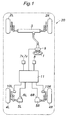
- FIG. 1 shows an outline of a vehicle with the present invention applied thereto.
- This vehicle 20 comprises a front wheel steering device 3 for directly steering right and left front wheels 2R and 2L according to the steering of a steering wheel 1, right and left actuators 5R and 5 L for individually changing toe angles of right and left rear wheels 4R and 4L by changing the length of, for example, right and left lateral links of a rear wheel suspension device which supports the right and left rear wheels 4R and 4L, right and left toe angle sensors 6R and 6L for individually detecting the toe angles of the right and left rear wheels 4R and 4L from the displacement amount of the right and left actuators 5R and 5L, a fore-and-aft acceleration sensor 7x for detecting a fore-and-aft acceleration acting on the vehicle body, a lateral acceleration sensor 7y for detecting a lateral acceleration, a yaw rate sensor 8 for detecting a yaw rate of the vehicle body, a steering angle sensor 9 for detecting a steering angle
- a rotary/linear motion converter combining an electric motor having a reduction gear and a screw mechanism, a cylinder device that linearly actuates a piston rod with hydraulic pressure, or any other known linear displacement actuator can be used.
- the toe-in and toe-out of the rear wheels 4R and 4L can be freely controlled as required by simultaneously actuating the right and left actuators 5R and 5L in a symmetric manner. Furthermore, by extending one of the right and left actuators 5R and 5L and retracting the other one, both of the rear wheels 4R and 4L can be steered either to the right or to the left.
- FIG. 2 shows a control block diagram showing the configuration of the control unit 11.
- the control unit 11 may comprise a microcomputer.
- a steering amount ⁇ f of the front wheels 2R and 2L is detected by the steering angle sensor 9 and is inputted into a feedforward computing unit 21.
- an output ⁇ x of the fore-and-aft acceleration sensor 7x mounted to the vehicle body is inputted into modified stability factor calculating unit 22.
- a modified stability factor A calculated from the fore-and-aft acceleration ⁇ x is inputted into the feedforward computing unit 21.
- a velocity V obtained by computing the average value of the outputs from the wheel velocity sensors 10 R and 10L of the rear wheels 4R and 4L is inputted into the feedforward computing unit 21.
- the feedforward computing unit 21 then, computes and outputs a feedforward control target value ⁇ r FF for the rear wheel steering angle (toe angle) from the inputted front wheel steering angle ⁇ f , modified stability factor A, vehicle velocity V and so on, as will be described later in detail.
- an output ⁇ y from the lateral acceleration sensor 7y mounted to the vehicle body and the above vehicle velocity V are inputted into a target yaw rate computing unit 23, and based on these inputted data, a target yaw rate ⁇ ref is computed and outputted.
- a rear wheel steering angle (toe angle) computing unit 24 computes a corrected rear wheel steering angle that minimizes this deviation, and outputs it as a feedback control target value ⁇ r FB for the rear wheel steering angle.
- the feedforward control target value ⁇ r FF is added to the feedback control target value ⁇ r FB to obtain a rear wheel steering angle (toe angle) control target value ⁇ r REF, which is then provided to the actuators 5R and 5L.
- the control unit 11 actuates the actuators 5 R and 5L such that the rear wheel steering angle ⁇ r becomes equal to the rear wheel steering angle control target value ⁇ r REF.
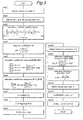
- control procedure of the present invention performed by the control unit 11 configured as above, is described with reference to Figure 3 .
- step 1 the vehicle velocity V is obtained by computing the average value of the outputs from the wheel velocity sensors 10R and 10 L of the rear wheels 4R and 4 L.
- the fore-and-aft acceleration ⁇ x is obtained from the output of the fore-and-aft acceleration sensor 7x.
- This value in addition to being directly obtained from the acceleration sensor, may also be obtained by other means such as estimating it from the differential value of the vehicle velocity.
- step 3 the modified stability factor value A is calculated (see the equation (8) shown below).
- step 4 a ratio c0 of the steady-state gain of the steering yaw rate transfer function property of the base vehicle (with acceleration/deceleration) to that of the ideal vehicle (without acceleration/deceleration) is obtained from the modified stability factor value A, steady-state stability factor A 0 , and vehicle velocity V obtained in Step 1.
- This value is a variable that varies depending on the vehicle velocity and fore-and-aft acceleration and can be obtained from a prescribed map or the like.
- step 5 a sequence of coefficients (a0 k , b0 k ) for digitally-representing the first half of an equation (or a transfer function property for the rear wheel steering angle ⁇ r to an input of the front wheel steering angle ⁇ f as given in Equation (3) below) which determines the rear wheel steering angle ⁇ r in relation to the front wheel steering angle ⁇ f so as to achieve a required steering yaw rate transfer function property (the reference steering yaw rate transfer function property) G ideal are computed.
- the transfer function on the left hand side in the block for step 5 is a phase-lead/lag property which depends on the vehicle velocity, and a0 k and b0 k are coefficients of a difference equation obtained by digitally-representing this transfer function.
- the digital representation of the transfer function is expressed as Hz0.
- step 6 a sequence of coefficients (a1 k , b1 k ) for digitally-representing the second half of the equation (3) is calculated.
- G ⁇ 0 is the steering yaw rate transfer function property when the rear wheel steering angle is 0 (i.e., is not controlled). Since G ⁇ 0 and G ideal are transfer functions which depend on the vehicle velocity, and as each of them is in the form of (first order function / second order function), G ideal / G ⁇ 0 is given in the form of (third order function / third order function).
- a1 k , b1 k are coefficients of a difference equation obtained when this function is converted into a discrete function and digitally-represented. The digital representation of this transfer function is expressed as Hz1.
- the steady-state gain of G ideal / G ⁇ 0 is a function of acceleration as described below, and corresponds to the value c0 obtained in step 4.
- step 7 the front wheel steering angle ⁇ f is inputted into the discrete transfer function Hz0 obtained in step 5, and the first half ⁇ r 1 of the equation (3) described below is calculated.
- step 8 the second half ⁇ r 2 of the equation (3) is calculated from Hz0 and Hz1.
- step 9 the rear wheel steering angle ⁇ r , which is the final result of the equation (3), is calculated based on the values obtained in step 7 and step 8, and stored as the feedforward rear wheel steering angle control target value ⁇ r FF.
- step 10 the feedback rear wheel steering angle control target value ⁇ r FB is calculated.
- step 10 the output ⁇ y from the lateral acceleration sensor 7y is obtained.
- step 11 a sequence of coefficients (a2 k , b2 k ) for digitally-representing the transfer function property G ⁇ (see equation (13) below) of the lateral acceleration ⁇ y and yaw rate ⁇ is calculated. This difference equation depends on the vehicle velocity which was obtained in step 1.
- step 12 the transfer function property G ⁇ obtained in step 11 is multiplied by the lateral acceleration ⁇ y obtained in step 10.
- the resulting value is divided by the vehicle velocity V to generate the target yaw rate ⁇ ref , which is the reference value of the feedback control (see equation (14) below).
- the division in the equation (14) becomes impossible. It is therefore necessary to make sure that division by zero does not occur in this computation.
- step 13 the actual yaw rate value is obtained from the output of yaw rate sensor 8. Then, in step 14, the feedback control target value ⁇ r FB of the rear wheel steering angle is calculated such that the actual yaw rate obtained in step 13 closely tracks the target yaw rate ⁇ ref calculated in step 12.
- a PID controller was used for adjustment. Also, a yaw moment that is expected to be generated by the rear wheel steering angle may be calculated.
- step 15 the feedforward control target value ⁇ r FF of the rear wheel steering angle, which was obtained in step 9, is added to the feedback control target value ⁇ r FB of the rear wheel steering angle, which was obtained in step 14, to determine the control target value ⁇ r of the rear wheel steering angle.
- ⁇ yaw rate
- s Laplace operator
- the desired reference steering yaw rate transfer function property G ideal can be readily obtained by controlling the transfer function property of the feedforward rear wheel steering angle control target value ⁇ r FF in relation to the front wheel actual steering angle ⁇ f ( ⁇ r / ⁇ f ).
- the rear wheel steering angle ⁇ r obtained from equation (3) is used as the feedforward rear wheel steering angle control target value ⁇ r FF.
- G ⁇ G ⁇ ⁇ 0 ⁇ 1 + V ⁇ s ⁇ I / k f ⁇ L + L f + V 2 ⁇ m ⁇ L r / k f ⁇ L / V ⁇ s ⁇ I / k r ⁇ L + L r + V 2 ⁇ m ⁇ L f / k r ⁇ L ⁇ ⁇ r / ⁇ f
- I yaw moment of inertia
- G ⁇ 0 transfer function property of the vehicle slip angle ⁇ in relation to the front wheel steering angle ⁇ f when the rear wheel steering angle is not controlled.
- the steering yaw rate ⁇ and the slip angle ⁇ cannot be arbitrarily determined.
- the rear wheel steering angle ⁇ r in a steady-state or feedforward rear wheel steering angle control target value ⁇ r FF) becomes 0 according to equation (3)
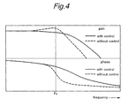
- Figure 4 shows a bode chart of steering yaw rate responses in presence and absence of rear wheel steering angle control, according to the present invention.
- the steady-state yaw rate gain is the same regardless of the presence of the control, however a pronounced resonance occurs in absence of the control at a certain frequency Fx, but no resonance is detected in presence of the control.
- the phase significantly changes near this yaw resonance so that there is a high likelihood that the vehicle may become unstable for a given input by a vehicle operator.
- the phase delay is small so that the vehicle is kept stable, and it is easier for the vehicle operator to handle the vehicle.
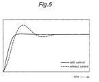
- Figure 5 shows yaw responses to a step steering input in presence and absence of rear wheel steering angle control according to the present invention.
- the front and rear wheel cornering powers k f and k r are constants k f 0 and k r 0, and the stability factor A is a constant A 0 .
- the yaw rate transfer function property G ⁇ o in relation to the front wheel steering angle can be expressed with the constant A 0 as the following equation (5').
- G ⁇ ⁇ o n 1 ⁇ s + V / L ⁇ 1 / 1 + A 0 ⁇ V 2 / d 2 ⁇ s 2 + d 1 ⁇ s + 1
- the stability factor A 0 at a constant velocity and steering yaw rate transfer function property G ⁇ o (based on the stability factor A 0 ) without rear wheel steering angle control can be obtained experimentally, for example, by driving the vehicle in slalom at a constant velocity and measuring data. Therefore, the rear wheel steering angle ⁇ r (feedforward control target value ⁇ r FF) for achieving the reference steering yaw rate transfer function property G ideal may be obtained by using the transfer function property G ⁇ o obtained from equation (5') in equation (3).
- the stability factor A in presence of acceleration/deceleration can be expressed with the fore-and-aft acceleration ⁇ x , stability factor A 0 without acceleration/deceleration, and cornering powers k f 0 and k r 0 generated when the vehicle is turning at a constant velocity as the following equation.
- A A 0 ⁇ L f / L f + h ⁇ ⁇ x ⁇ L f ⁇ k f ⁇ 0 - L r / L r - h ⁇ ⁇ x ⁇ L r ⁇ k r ⁇ 0 / L f ⁇ k f ⁇ 0 - L r ⁇ k r ⁇ 0 0
- Figure 6 shows the graph of equation (8). As shown in the figure, when a vehicle without rear wheel steering angle control accelerates while turning, it understeers. On the other hand, when it decelerates while turning, it oversteers.
- the stability factor A given by equation (8) is used as the modified stability factor (i.e., both of equation (5) and equation (8) are used) instead of the stability factor A 0 (which was used in equation (5') to determine G ⁇ o used in equation (3)). Therefore, the rear wheel steering angle is controlled by the feedforward rear wheel steering angle control target value ⁇ r FF that matches the actual stability factor, which changes according to the vehicle fore-and-aft acceleration/deceleration, thereby preventing the vehicle operator from experiencing an unfamiliar feeling regarding the vehicle handling and improving vehicle stability and responsiveness.
- one of the factors that could disturb vehicle motion stability is the acceleration/deceleration during a turn. This is because, as is obvious from equation (8), when the vehicle accelerates/decelerates during a turn, the fore-and-aft load distribution changes, and thus the vehicle turning property changes.
- the feedforward control target value of the rear wheel steering angle is adjusted automatically according to changes in turning property, the vehicle behavior maintains stability even when the vehicle is accelerating/decelerating during a turn. Therefore, according to the present invention, even when the vehicle is accelerating/decelerating, the vehicle operator can be prevented from experiencing an unfamiliar feeling regarding the vehicle handling, and vehicle responsiveness and stability can be improved.
- ⁇ f , ⁇ r slip angles of front and rear wheels
- I vehicle yaw moment of inertia
- m vehicle mass.
- the time rate change of the vehicle slip angle ⁇ (d ⁇ / dt) can be expressed by the lateral acceleration ⁇ y , vehicle velocity V, and yaw rate ⁇ , as the following equation.
- d ⁇ ⁇ / dt ⁇ y / V - ⁇
- the rear wheel steering angle is feedback-controlled (i.e., the feedback rear wheel steering angle target value ⁇ r FB is adjusted) such that the actual yaw rate ⁇ becomes identical to this target yaw rate ⁇ ref calculated from the vehicle velocity V and the actual lateral acceleration ⁇ y .
- the feedforward-control which is performed to achieve the reference steering yaw rate property G ideal based on equation (3), even when the road friction coefficient ⁇ and other parameters change, the lateral acceleration ⁇ y changes only in a corresponding manner, and ⁇ ref changes as a result thereof so that a yaw rate inappropriate for the road condition will not be generated.
- not only the effects of the road friction coefficient ⁇ but also those of changes in various properties of the vehicle including vehicle mass change (caused, for example, by the number of vehicle occupants) will be reduced.
- the steady-state property of the reference steering yaw rate transfer function property which is used to determine the rear wheel steering angle feedforward control target value from the front wheel steering angle
- the slip angle ⁇ is controlled to be the same as it would be when the rear wheel steering angle is not controlled, thereby preventing the vehicle operator from experiencing an unfamiliar feeling regarding the vehicle handling.
- the feedforward target rear wheel steering angle is set according to changes in vehicle steer property caused by fore-and-aft acceleration, thereby preventing the vehicle operator from experiencing an unfamiliar feeling regarding the vehicle handling and improving vehicle stability and responsiveness even when the vehicle is accelerating or decelerating.
- the target yaw rate is set according to changes in road condition, and the feedback rear wheel steering angle control target value is determined accordingly, the controlling device can be configured to be stable against changes in road condition and show a highly robust stability. Therefore, the rear wheel steering angle controlling device for vehicles of the present invention is extremely useful in industry.
Landscapes
- Engineering & Computer Science (AREA)
- Physics & Mathematics (AREA)
- Mathematical Physics (AREA)
- Theoretical Computer Science (AREA)
- Chemical & Material Sciences (AREA)
- Combustion & Propulsion (AREA)
- Transportation (AREA)
- Mechanical Engineering (AREA)
- Steering Control In Accordance With Driving Conditions (AREA)
- Steering-Linkage Mechanisms And Four-Wheel Steering (AREA)
Abstract
Description
- The present invention relates to a vehicle rear wheel steering angle controlling device for changing the rear wheel steering angle.
- There is known a rear wheel toe angle controlling device configured to change the toe angles of right and left rear wheels individually by extending and retracting linear displacement actuators such as hydraulic cylinders mounted to parts of the vehicle body where lateral links or trailing links of a suspension device supporting the right and left rear wheels are joined (see Japanese patent laid open publication (kokai) No.
09-30438 - Conventional rear wheel steering controllers, including the one disclosed in the above Japanese patent laid open publication, are configured to control the rear wheel steering angle according to the turning behavior of the vehicle and thus improve vehicle stability and responsiveness. In such a rear wheel steering angle control, it is a common practice to determine a control target value of the rear wheel steering angle according to the front wheel steering angle, lateral acceleration, and/or yaw rate. According to one of such known control mechanisms, the rear wheel steering angle is controlled such that the slip angle becomes 0 (See Japanese Patent No.
3, 179, 271 - A steady-state value of a vehicle slip angle β of a vehicle where only front wheels are steered can be obtained from the following equation:

- In addtition, as is obvious from
Figure 7 which shows the relation between (vehicle slip angle β / front wheel steering angle δf) and vehicle velocity V of vehicles having understeer, neutral steer and oversteer properties, the slip angle β has a positive value when the vehicle velocity is 0 and changes toward a negative value as the vehicle velocity increases, regardless of the steer property. This means that a vehicle turning with a low velocity tends to head outwardly from a regular turning radius, while a vehicle turning with a high velocity tends to head inwardly into a regular turning radius. As is obvious from equation (1) andFigure 7 , since the slip angle changes according to the vehicle velocity, regardless of the steer property, when the rear wheel steering angle is variably controlled such that the slip angle becomes 0 regardless of the vehicle velocity, a vehicle operator who is used to drive vehicles where only front wheels are steered will feel that the vehicle turns more than intended. In addition, when the vehicle accelerates or when there is a sudden change in road condition, the conventional rear wheel steering angle controlling mechanisms are not able to properly deal with these changes, and this may cause a discomfort to the vehicle operator. - The present invention was conceived in view of such problems of the prior art and its main object is to provide a rear wheel steering angle controlling device which can prevent the vehicle operator from experiencing a discomfort regarding the vehicle handling and improve vehicle stability and yaw responsiveness.
- According to the present invention, to solve the above-mentioned problems, there is provided a rear wheel steering angle controlling device for vehicles comprising: a rear wheel steering mechanism (5R, 5L) for changing a rear wheel steering angle; a front wheel steering angle detector (9) for detecting a front wheel steering angle (δf); a vehicle velocity detector (10R, 10L) for detecting a vehicle velocity (V); a feedforward rear wheel steering angle control target value setting unit (21) for setting a feedforward control target value (δr FF) of said rear wheel steering angle according to said front wheel steering angle, said vehicle velocity, a steering yaw rate transfer function property (Gγ0) without a rear wheel steering angle control and a prescribed reference steering yaw rate transfer function property (Gideal); and a controlling device (11) for controlling said rear wheel steering mechanism according to said feedforward rear wheel steering angle control target value; wherein a steady-state property of said reference steering yaw rate transfer function property is configured to be identical to said steering yaw rate transfer function property without said rear wheel steering angle control. The rear wheel steering mechanism may comprise, for example, actuators capable of controlling the toe angles of right and left rear wheels individually. In addition, the vehicle velocity detector may include vehicle wheel velocity sensors mounted to rear wheels. The vehicle velocity can also be obtained by integrating the acceleration obtained from acceleration sensors. The acceleration may also be obtained by differentiating the vehicle velocity.
- According to the rear wheel steering angle controlling device for vehicles configured as above, in a transient state, vehicle responsiveness and stability can be improved by controlling the rear wheel steering angle, while in a steady state, the vehicle operator can be prevented from experiencing an unfamiliar feeling or otherwise experiencing discomfort regarding the vehicle handling by controlling the slip angle β to be the same as it would be when the rear wheel steering angle is not controlled.
- Furthermore, according to another aspect of the present invention, there is provided a rear wheel steering angle controlling device for vehicles, comprising: a rear wheel steering mechanism (5R, 5L) for changing a rear wheel steering angle; a front wheel steering angle detector (9) for detecting a front wheel steering angle (δf); a vehicle velocity detector (10R, 10L) for detecting a vehicle velocity (V); a fore-and-aft acceleration/deceleration detector (7x) for detecting a fore-and-aft acceleration/deceleration of said vehicle; a feedforward rear wheel steering angle control target value setting unit (21) for setting a feedforward control target value of said rear wheel steering angle according to said front wheel steering angle and said vehicle velocity; and a controlling device (11) for controlling said rear wheel steering mechanism according to said feedforward rear wheel steering angle control target value; wherein said rear wheel steering angle feedforward control target value setting unit changes said feedforward rear wheel steering angle control target value according to a change in a vehicle steer property caused by said fore-and-aft acceleration/deceleration of said vehicle. This is preferably achieved, for example, by modifying a stability factor used for computing the steering yaw rate transfer function property without rear wheel steering angle control according to changes in vehicle steer property caused by acceleration/deceleration of said vehicle, when said feedforward rear wheel steering angle control target value setting unit sets said feedforward rear wheel steering angle control target value according to said front wheel steering angle, said vehicle velocity, the steering yaw rate transfer function property without rear wheel steering angle control, and the prescribed reference steering yaw rate transfer function property. Thus, changes in the steer property of the vehicle caused by its acceleration/deceleration can be addressed, thereby preventing the vehicle operator from experiencing an unfamiliar feeling regarding the vehicle handling even when the vehicle is accelerating or decelerating, and improving vehicle stability and responsiveness.
- More preferably, the rear wheel steering angle controlling device for vehicles of the present invention further comprises a yaw rate detector (8) for detecting a yaw rate of said vehicle; a lateral acceleration detector (7y) for detecting a lateral acceleration of said vehicle; a target yaw rate setting unit (23) for determining a target yaw rate from said vehicle velocity and said lateral acceleration; and a feedback rear wheel steering angle control target value setting unit (24) for determining a feedback rear wheel steering angle control target value according to a difference between a yaw rate detected by said yaw rate detector and said target yaw rate; wherein said rear wheel steering mechanism is controlled according to a rear wheel steering angle control target value (δf REF) obtained by adding said feedforward rear wheel steering angle control target value to said feedback rear wheel steering angle control target value. Therefore, even when the lateral acceleration changes as a result of changes in road condition, the feedback rear wheel steering angle control target value can be determined based on the target yaw rate, which has been set according to changes in the lateral acceleration. Thus, the controlling device can be configured to have a highly robust stability and to be stable against changes in road condition. A transfer function (Gα) which defines the relation between the velocity, lateral acceleration, and target yaw rate is preferred to reflect the feedforward rear wheel steering angle control.
- According to the present invention, in a transient state, vehicle stability and responsiveness can be improved by controlling the rear wheel steering angle, while in a steady state, the slip angle β can be controlled to be the same as it would be when the rear wheel steering angle is not controlled, and thus the vehicle operator can be prevented from experiencing an unfamiliar feeling regarding the vehicle handling. In addition, when the vehicle is turning with acceleration/deceleration, changes in the vehicle turning property caused by a fore-and-aft shifting of the vehicle load can be addressed automatically, thereby preventing the vehicle operator from experiencing an unfamiliar feeling regarding the vehicle handling and improving vehicle stability and responsiveness even when the vehicle is turning with acceleration/deceleration. Furthermore, the controlling device can be configured to be able to perform control actions appropriately according to changes in road condition.
-
-
Figure 1 is a schematic configuration diagram of a vehicle to which the present invention is applied. -
Figure 2 is a schematic block diagram of the control of the present invention. -
Figure 3 is a schematic flow diagram of the control of the present invention. -
Figure 4 is a bode chart of the transfer function property of steering yaw rate. -
Figure 5 is a graph showing a yaw rate response to a step steering input; -
Figure 6 is a graph showing changes of stability factor with acceleration/deceleration; and -
Figure 7 is a graph showing the relation between (vehicle slip angle / steering angle) and vehicle velocity. - The present invention is described below in detail with reference to accompanying drawings.
-
Figure 1 shows an outline of a vehicle with the present invention applied thereto. Thisvehicle 20 comprises a frontwheel steering device 3 for directly steering right and leftfront wheels steering wheel 1, right andleft actuators rear wheels rear wheels toe angle sensors rear wheels left actuators aft acceleration sensor 7x for detecting a fore-and-aft acceleration acting on the vehicle body, alateral acceleration sensor 7y for detecting a lateral acceleration, ayaw rate sensor 8 for detecting a yaw rate of the vehicle body, a steering angle sensor 9 for detecting a steering angle of thesteering wheel 1,wheel velocity sensors rear wheels control unit 11 for controlling the displacement of each of theactuators - For the
actuators - According to the toe angle variable control system configured as above, the toe-in and toe-out of the
rear wheels left actuators left actuators rear wheels -
Figure 2 shows a control block diagram showing the configuration of thecontrol unit 11. Thecontrol unit 11 may comprise a microcomputer. A steering amount δf of thefront wheels feedforward computing unit 21. In addition, an output αx of the fore-and-aft acceleration sensor 7x mounted to the vehicle body, is inputted into modified stabilityfactor calculating unit 22. Then, a modified stability factor A calculated from the fore-and-aft acceleration αx is inputted into thefeedforward computing unit 21. A velocity V obtained by computing the average value of the outputs from thewheel velocity sensors rear wheels feedforward computing unit 21. Thefeedforward computing unit 21, then, computes and outputs a feedforward control target value δrFF for the rear wheel steering angle (toe angle) from the inputted front wheel steering angle δf, modified stability factor A, vehicle velocity V and so on, as will be described later in detail. - In addition, an output αy from the
lateral acceleration sensor 7y mounted to the vehicle body and the above vehicle velocity V are inputted into a target yawrate computing unit 23, and based on these inputted data, a target yaw rate γref is computed and outputted. - Then, the deviation between an output γ from the
yaw rate sensor 8 mounted to the vehicle body and the output γref from the target yawrate computing unit 23 is calculated. A rear wheel steering angle (toe angle)computing unit 24 computes a corrected rear wheel steering angle that minimizes this deviation, and outputs it as a feedback control target value δrFB for the rear wheel steering angle. - Then, the feedforward control target value δrFF is added to the feedback control target value δrFB to obtain a rear wheel steering angle (toe angle) control target value δrREF, which is then provided to the
actuators control unit 11 actuates theactuators - Next, the control procedure of the present invention, performed by the
control unit 11 configured as above, is described with reference toFigure 3 . - First, in
step 1, the vehicle velocity V is obtained by computing the average value of the outputs from thewheel velocity sensors rear wheels - Next, in
step 2, the fore-and-aft acceleration αx is obtained from the output of the fore-and-aft acceleration sensor 7x. This value, in addition to being directly obtained from the acceleration sensor, may also be obtained by other means such as estimating it from the differential value of the vehicle velocity. - Next, in
step 3, the modified stability factor value A is calculated (see the equation (8) shown below). In step 4, a ratio c0 of the steady-state gain of the steering yaw rate transfer function property of the base vehicle (with acceleration/deceleration) to that of the ideal vehicle (without acceleration/deceleration) is obtained from the modified stability factor value A, steady-state stability factor A0, and vehicle velocity V obtained inStep 1. This value is a variable that varies depending on the vehicle velocity and fore-and-aft acceleration and can be obtained from a prescribed map or the like. - Next, in step 5, a sequence of coefficients (a0k, b0k) for digitally-representing the first half of an equation (or a transfer function property for the rear wheel steering angle δr to an input of the front wheel steering angle δf as given in Equation (3) below) which determines the rear wheel steering angle δr in relation to the front wheel steering angle δf so as to achieve a required steering yaw rate transfer function property (the reference steering yaw rate transfer function property) Gideal are computed. The transfer function on the left hand side in the block for step 5 is a phase-lead/lag property which depends on the vehicle velocity, and a0k and b0k are coefficients of a difference equation obtained by digitally-representing this transfer function. The digital representation of the transfer function is expressed as Hz0.
- Next, in
step 6, a sequence of coefficients (a1k, b1k) for digitally-representing the second half of the equation (3) is calculated. Gγ0 is the steering yaw rate transfer function property when the rear wheel steering angle is 0 (i.e., is not controlled). Since Gγ0 and Gideal are transfer functions which depend on the vehicle velocity, and as each of them is in the form of (first order function / second order function), Gideal / Gγ0 is given in the form of (third order function / third order function). a1k, b1k are coefficients of a difference equation obtained when this function is converted into a discrete function and digitally-represented. The digital representation of this transfer function is expressed as Hz1. - The steady-state gain of Gideal / Gγ0 is a function of acceleration as described below, and corresponds to the value c0 obtained in step 4.
- Next, in
step 7, the front wheel steering angle δf is inputted into the discrete transfer function Hz0 obtained in step 5, and thefirst half δ r1 of the equation (3) described below is calculated. Instep 8, thesecond half δ r2 of the equation (3) is calculated from Hz0 and Hz1. - Next, in step 9, the rear wheel steering angle δr, which is the final result of the equation (3), is calculated based on the values obtained in
step 7 andstep 8, and stored as the feedforward rear wheel steering angle control target value δrFF. - From step 10 to step 14, the feedback rear wheel steering angle control target value δrFB is calculated. First, in step 10, the output αy from the
lateral acceleration sensor 7y is obtained. Instep 11, a sequence of coefficients (a2k, b2k) for digitally-representing the transfer function property Gα (see equation (13) below) of the lateral acceleration αy and yaw rate γ is calculated. This difference equation depends on the vehicle velocity which was obtained instep 1. Next, in step 12, the transfer function property Gα obtained instep 11 is multiplied by the lateral acceleration αy obtained in step 10. Then, the resulting value is divided by the vehicle velocity V to generate the target yaw rate γref, which is the reference value of the feedback control (see equation (14) below). When the vehicle velocity V is 0 or quite low, the division in the equation (14) becomes impossible. It is therefore necessary to make sure that division by zero does not occur in this computation. - Next, in step 13, the actual yaw rate value is obtained from the output of
yaw rate sensor 8. Then, in step 14, the feedback control target value δrFB of the rear wheel steering angle is calculated such that the actual yaw rate obtained in step 13 closely tracks the target yaw rate γref calculated in step 12. In this embodiment, a PID controller was used for adjustment. Also, a yaw moment that is expected to be generated by the rear wheel steering angle may be calculated. - In step 15, the feedforward control target value δrFF of the rear wheel steering angle, which was obtained in step 9, is added to the feedback control target value δrFB of the rear wheel steering angle, which was obtained in step 14, to determine the control target value δr of the rear wheel steering angle.
- Next, each part of the control of the present invention is described in detail.
- When the rear wheel steering angle δr for a given input of the front wheel actual steering angle δf is represented by a certain transfer function (δr / δf), the steering yaw rate transfer function property (Gγ=γ / δf), which is a transfer function property of the yaw rate γ in relation to the front wheel actual steering angle δf can be expressed as given in the following equation by using Gγ0, which is the steering yaw rate transfer function property when the rear wheel steering angle is 0 (i.e., when the rear wheel steering angle is not controlled):

- By calculating back the equation (2), it will be obvious that in order to make the actual steering yaw rate transfer function property Gγ be identical to the required reference steering yaw rate transfer function property Gideal, the relation (transfer function) between the rear wheel steering angle δr and the front wheel steering angle δf may be as follows.

- Therefore, by measuring the steering yaw rate function property Gγo without rear wheel steering angle control, the desired reference steering yaw rate transfer function property Gideal can be readily obtained by controlling the transfer function property of the feedforward rear wheel steering angle control target value δrFF in relation to the front wheel actual steering angle δf (δr / δf). The rear wheel steering angle δr obtained from equation (3) is used as the feedforward rear wheel steering angle control target value δrFF.
- When the rear wheel steering angle δr for a given input of the front wheel actual ateering angle δf is represented by a certain transfer function (δr / δf) as in equation (2), the transfer function property Gβ of the vehicle slip angle β in relation to the front wheel steering angle δf can be expressed as follows:

- Thus, the steering yaw rate γ and the slip angle β cannot be arbitrarily determined. However, if it is supposed that the steady-state value of the steering yaw rate becomes the same as the steering yaw rate without rear wheel steering angle control (i.e., when steady-state Gideal = Gγo), because the rear wheel steering angle δr in a steady-state (or feedforward rear wheel steering angle control target value δrFF) becomes 0 according to equation (3), equation (4) gives the steady-state slip angle transfer function property or yields Gβ = Gβ0. This means that by adjusting the steady-state property of the reference steering yaw rate transfer function property Gideal such that it becomes the same as the steering yaw rate transfer function property without rear wheel steering angle control, the steady-state property of the slip angle β becomes the same as it would be when the rear wheel steering angle is not controlled, and thus the unfamiliar feeling that the vehicle operator may experience regarding the vehicle handling can be reduced or prevented.
- In a transient state, even when Gideal ≠ Gγo, by performing feedforward control to achieve the rear wheel steering angle δr obtained from equation (3) (i.e., by using the rear wheel steering angle δr obtained in equation (3) as the feedforward rear wheel steering angle control target value δrFF), the actual yaw rate response can be adjusted to become identical to Gideal, thereby improving vehicle stability and responsiveness.
-
Figure 4 shows a bode chart of steering yaw rate responses in presence and absence of rear wheel steering angle control, according to the present invention. As described above, the steady-state yaw rate gain is the same regardless of the presence of the control, however a pronounced resonance occurs in absence of the control at a certain frequency Fx, but no resonance is detected in presence of the control. - Also, in absence of the control, the phase significantly changes near this yaw resonance so that there is a high likelihood that the vehicle may become unstable for a given input by a vehicle operator. On the other hand, in presence of the control, since there is no yaw resonance, the phase delay is small so that the vehicle is kept stable, and it is easier for the vehicle operator to handle the vehicle.
-
Figure 5 shows yaw responses to a step steering input in presence and absence of rear wheel steering angle control according to the present invention. - As also evidenced by the bode diagram in
Figure 4 showing frequency properties, in presence of the control, the yaw rate in relation to steering input shows a high response without oscillation. In other words, in presence of the control, even if the yaw rate steady-state value is the same as that in absence of the control, the response is faster. - Next is described the control action of the present invention when the vehicle is accelerating/decelerating while turning.
- When the rear wheel steering angle is not controlled, the yaw rate transfer function property Gγo in relation to the front wheel steering angle can be expressed as follows:

- The zero-order term of equation (5) ((V / L) · [1 / (1 + A · V2)]) is a yaw rate steady-state gain, and A is a stability factor which can be expressed as follows:

- In a linear region, when the vehicle is turning at a constant velocity, the front and rear wheel cornering powers kf and kr are
constants k f0 andk r0, and the stability factor A is a constant A0. When the rear wheel steering angle is not controlled, the yaw rate transfer function property Gγo in relation to the front wheel steering angle can be expressed with the constant A0 as the following equation (5').
- The stability factor A0 at a constant velocity and steering yaw rate transfer function property Gγo (based on the stability factor A0) without rear wheel steering angle control can be obtained experimentally, for example, by driving the vehicle in slalom at a constant velocity and measuring data. Therefore, the rear wheel steering angle δr (feedforward control target value δrFF) for achieving the reference steering yaw rate transfer function property Gideal may be obtained by using the transfer function property Gγo obtained from equation (5') in equation (3).
- However, if the rear wheel steering angle is controlled by using the steering yaw rate transfer function property Gγo without the control, which can be obtained from the stability factor A0 at a constant velocity, when the vehicle is braked or accelerated during steering, it may be impossible to achieve a desired vehicle behavior. This is due to changes in vehicle turning properties, which are caused by the alteration of the stability factor A during acceleration or deceleration. Thus, when there is a fore-and-aft vehicle load shift of h · m · αx / L, the cornering powers of front and rear wheels (kf and kr) change according to the following equation:

- From equation (7), the stability factor A in presence of acceleration/deceleration can be expressed with the fore-and-aft acceleration αx, stability factor A0 without acceleration/deceleration, and cornering
powers k f0 andk r0 generated when the vehicle is turning at a constant velocity as the following equation.
-
Figure 6 shows the graph of equation (8). As shown in the figure, when a vehicle without rear wheel steering angle control accelerates while turning, it understeers. On the other hand, when it decelerates while turning, it oversteers. - According to the present invention, to appropriately set the feedforward rear wheel steering angle control target value δrFF according to changes in steer property, which occur with acceleration/deceleration, the stability factor A given by equation (8) is used as the modified stability factor (i.e., both of equation (5) and equation (8) are used) instead of the stability factor A0 (which was used in equation (5') to determine Gγo used in equation (3)). Therefore, the rear wheel steering angle is controlled by the feedforward rear wheel steering angle control target value δrFF that matches the actual stability factor, which changes according to the vehicle fore-and-aft acceleration/deceleration, thereby preventing the vehicle operator from experiencing an unfamiliar feeling regarding the vehicle handling and improving vehicle stability and responsiveness.
- As described above, one of the factors that could disturb vehicle motion stability is the acceleration/deceleration during a turn. This is because, as is obvious from equation (8), when the vehicle accelerates/decelerates during a turn, the fore-and-aft load distribution changes, and thus the vehicle turning property changes. However, according to the present invention, as the feedforward control target value of the rear wheel steering angle is adjusted automatically according to changes in turning property, the vehicle behavior maintains stability even when the vehicle is accelerating/decelerating during a turn. Therefore, according to the present invention, even when the vehicle is accelerating/decelerating, the vehicle operator can be prevented from experiencing an unfamiliar feeling regarding the vehicle handling, and vehicle responsiveness and stability can be improved.
- Next is described a method for controlling with high precision even when various properties of the vehicle change. By using this method, the adaptability of the vehicle, especially to the cornering power, which may change dramatically depending on the road friction coefficient, is improved.
- The motion equations of the lateral acceleration αy and yaw rate γ can be expressed as follows:


- These equations (9) and (10) show that if the cornering powers kf and kr change significantly as a result of a change in road condition, while the yaw rate γ will not change significantly as being the difference between the moments that act upon the front and rear parts of the vehicle, the lateral acceleration αy will change significantly since it is determined by the sum of the lateral forces that act upon the front and rear parts of the vehicle.
- These equations, on the other hand, show that if the road friction coefficient µ has decreased due to road condition such as snow cover, the yaw rate γ can be changed by changing the rear wheel toe angle (i.e., rear wheel slip angle βr), while the lateral acceleration αy cannot be changed significantly.
- When the slip is small, the time rate change of the vehicle slip angle β (dβ / dt) can be expressed by the lateral acceleration αy, vehicle velocity V, and yaw rate γ, as the following equation.

- When the vehicle slip angle converges or settles to a steady-state value, the steady-state value of the time rate change of the vehicle slip angle becomes 0, and thus the steady-state value of the target yaw rate (γg) set to match the road friction coefficient µ will be as follows.

- When a vehicle with a road friction coefficient µ (normally, high) is controlled by using the feedforward rear wheel steering angle control target value δrFF obtained from equation (3), the relation between the lateral acceleration αy and yaw rate γ (Gα) can be expressed as the following equation.


- The rear wheel steering angle is feedback-controlled (i.e., the feedback rear wheel steering angle target value δrFB is adjusted) such that the actual yaw rate γ becomes identical to this target yaw rate γref calculated from the vehicle velocity V and the actual lateral acceleration αy. In the present invention, by performing such feedback control on the rear wheel steering angle in addition to the feedforward-control, which is performed to achieve the reference steering yaw rate property Gideal based on equation (3), even when the road friction coefficient µ and other parameters change, the lateral acceleration αy changes only in a corresponding manner, and γref changes as a result thereof so that a yaw rate inappropriate for the road condition will not be generated. In addition, not only the effects of the road friction coefficient µ but also those of changes in various properties of the vehicle including vehicle mass change (caused, for example, by the number of vehicle occupants) will be reduced.
- As described hereinabove, according to the rear wheel steering angle controlling device for vehicles of the present invention, as the steady-state property of the reference steering yaw rate transfer function property, which is used to determine the rear wheel steering angle feedforward control target value from the front wheel steering angle, is regulated so as to become identical to the steering yaw rate transfer function property without rear wheel steering angle control, in a transition state, vehicle responsiveness and stability can be improved by controlling the rear wheel steering angle. Meanwhile, in a steady state, the slip angle β is controlled to be the same as it would be when the rear wheel steering angle is not controlled, thereby preventing the vehicle operator from experiencing an unfamiliar feeling regarding the vehicle handling. In addition, the feedforward target rear wheel steering angle is set according to changes in vehicle steer property caused by fore-and-aft acceleration, thereby preventing the vehicle operator from experiencing an unfamiliar feeling regarding the vehicle handling and improving vehicle stability and responsiveness even when the vehicle is accelerating or decelerating. Furthermore, because the target yaw rate is set according to changes in road condition, and the feedback rear wheel steering angle control target value is determined accordingly, the controlling device can be configured to be stable against changes in road condition and show a highly robust stability. Therefore, the rear wheel steering angle controlling device for vehicles of the present invention is extremely useful in industry.
- Although the invention has been described with reference to preferred embodiments, those skilled in the art will easily understand that various modifications and changes can be made without departing from the scope of the present invention.
- It should be noted that the disclosure of the basic application of the present application from which the Paris Convention Priority is claimed and all prior art mentioned in this specification are incorporated herein by reference.
Claims (4)
- A rear wheel steering angle controlling device for vehicles, comprising:a rear wheel steering mechanism for changing a rear wheel steering angle;a front wheel steering angle detector for detecting a front wheel steering angle;a vehicle velocity detector for detecting a vehicle velocity;a feedforward rear wheel steering angle control target value setting unit for setting a feedforward control target value of said rear wheel steering angle according to said front wheel steering angle, said vehicle velocity, a steering yaw rate transfer function property without a rear wheel steering angle control and a prescribed reference steering yaw rate transfer function property; anda controlling device for controlling said rear wheel steering mechanism according to said feedforward rear wheel steering angle control target value;wherein a steady-state property of said reference steering yaw rate transfer function property is configured to be identical to said steering yaw rate transfer function property without said rear wheel steering angle control.
- A rear wheel steering angle controlling device for vehicles, comprising:a rear wheel steering mechanism for changing a rear wheel steering angle;a front wheel steering angle detector for detecting a front wheel steering angle;a vehicle velocity detector for detecting a vehicle velocity;a fore-and-aft acceleration/deceleration detector for detecting a fore-and-aft acceleration/deceleration of said vehicle;a feedforward rear wheel steering angle control target value setting unit for setting a feedforward control target value of said rear wheel steering angle according to said front wheel steering angle and said vehicle velocity; anda controlling device for controlling said rear wheel steering mechanism according to said feedforward rear wheel steering angle control target value;wherein said rear wheel steering angle feedforward control target value setting unit changes said feedforward rear wheel steering angle control target value according to a change in a vehicle steer property caused by said fore-and-aft acceleration/deceleration of said vehicle.
- The rear wheel steering angle controlling device for vehicles according to claim 2, wherein said feedforward rear wheel steering angle control target value setting unit sets said feedforward rear wheel steering angle control target value according to said front wheel steering angle, said vehicle velocity, the steering yaw rate transfer function property without rear wheel steering angle control, and the prescribed reference steering yaw rate transfer function property, and modifies a stability factor used for calculating said steering yaw rate transfer function property without rear wheel steering angle control according to changes in a vehicle steer property caused by said fore-and-aft acceleration/deceleration of said vehicle.
- A rear wheel steering angle controlling device for vehicles according to one of claims 1 to 3, further comprising:a yaw rate detector for detecting a yaw rate of said vehicle;a lateral acceleration detector for detecting a lateral acceleration of said vehicle;a target yaw rate setting unit for determining a target yaw rate from said vehicle velocity and said lateral acceleration; anda feedback rear wheel steering angle control target value setting unit for determining a feedback rear wheel steering angle control target value according to a difference between a yaw rate detected by said yaw rate detector and said target yaw rate;wherein said rear wheel steering mechanism is controlled according to a rear wheel steering angle control target value obtained by adding said feedforward rear wheel steering angle control target value to said feedback rear wheel steering angle control target value.
Applications Claiming Priority (2)
| Application Number | Priority Date | Filing Date | Title |
|---|---|---|---|
| JP2006285722 | 2006-10-20 | ||
| PCT/JP2007/001140 WO2008047481A1 (en) | 2006-10-20 | 2007-10-19 | Vehicle rear wheel steered angle controller |
Publications (3)
| Publication Number | Publication Date |
|---|---|
| EP2085293A1 true EP2085293A1 (en) | 2009-08-05 |
| EP2085293A4 EP2085293A4 (en) | 2009-11-11 |
| EP2085293B1 EP2085293B1 (en) | 2011-03-16 |
Family
ID=39313737
Family Applications (1)
| Application Number | Title | Priority Date | Filing Date |
|---|---|---|---|
| EP07827919A Not-in-force EP2085293B1 (en) | 2006-10-20 | 2007-10-19 | Rear wheel steering angle controlling device for vehicles |
Country Status (6)
| Country | Link |
|---|---|
| US (1) | US8554416B2 (en) |
| EP (1) | EP2085293B1 (en) |
| JP (1) | JP5135224B2 (en) |
| CA (1) | CA2661781C (en) |
| DE (1) | DE602007013267D1 (en) |
| WO (1) | WO2008047481A1 (en) |
Cited By (4)
| Publication number | Priority date | Publication date | Assignee | Title |
|---|---|---|---|---|
| US8494719B2 (en) | 2009-02-12 | 2013-07-23 | GM Global Technology Operations LLC | Method and apparatus for controlling active rear steering |
| CN105835873A (en) * | 2015-02-02 | 2016-08-10 | 本田技研工业株式会社 | Vehicle behavior information acquisition device and vehicle travel control device |
| CN113721620A (en) * | 2021-08-30 | 2021-11-30 | 山东交通学院 | Particle swarm-genetic hybrid algorithm-based vehicle transverse PID control method |
| US20220219754A1 (en) * | 2021-01-11 | 2022-07-14 | Hyundai Mobis Co., Ltd. | Method for rear steering control of a vehicle |
Families Citing this family (19)
| Publication number | Priority date | Publication date | Assignee | Title |
|---|---|---|---|---|
| US8068955B2 (en) * | 2008-01-08 | 2011-11-29 | Honda Motor Co., Ltd. | Vehicle with a variable rear toe angle |
| CN101959746B (en) * | 2008-03-10 | 2013-07-17 | 本田技研工业株式会社 | Vehicle Maneuverability Controls |
| EP2210790B1 (en) | 2008-03-11 | 2012-12-26 | Honda Motor Co., Ltd. | Vehicle behavior stabilization control device |
| JP5297117B2 (en) * | 2008-08-19 | 2013-09-25 | 富士重工業株式会社 | Vehicle behavior control device |
| JP5384905B2 (en) * | 2008-10-16 | 2014-01-08 | 本田技研工業株式会社 | Steering angle ratio variable control device |
| US9194566B2 (en) * | 2012-06-08 | 2015-11-24 | Lg Innotek Co., Ltd. | Lamp unit and vehicle lamp apparatus using the same |
| JP6081349B2 (en) * | 2013-12-24 | 2017-02-15 | 本田技研工業株式会社 | Vehicle turning control system |
| KR102202752B1 (en) * | 2017-06-30 | 2021-01-14 | 현대모비스 주식회사 | Method for controlling rear wheel steering in vehicle and apparatus thereof |
| JP6734905B2 (en) * | 2018-11-07 | 2020-08-05 | 本田技研工業株式会社 | Vehicle behavior stabilization device |
| KR102703074B1 (en) * | 2019-12-20 | 2024-09-06 | 현대자동차주식회사 | Control apparatus and method of rear wheel steer |
| CN113276942B (en) * | 2020-02-19 | 2022-07-26 | 广州汽车集团股份有限公司 | A rear wheel active steering control method, system and control device thereof |
| CN111703503B (en) * | 2020-05-26 | 2022-08-23 | 江苏大学 | System and method for controlling toe-in angle of front wheel of suspension combined with automatic driving module |
| KR102791576B1 (en) * | 2020-08-24 | 2025-04-04 | 현대자동차주식회사 | Driving stabilization method for wheel motor driven vehicle |
| CN114194286B (en) * | 2022-01-04 | 2023-11-03 | 吉林大学 | Dual-mode rear wheel active steering device based on differential principle |
| GB2618545B (en) * | 2022-05-09 | 2024-10-16 | Jaguar Land Rover Ltd | Control system and method for vehicle steering |
| CN115158459B (en) * | 2022-07-11 | 2024-01-16 | 上汽通用汽车有限公司 | Rear wheel steering angle control method, apparatus, device and computer readable storage medium |
| CN119078957A (en) * | 2023-06-06 | 2024-12-06 | 英业达科技有限公司 | Rear wheel steering system |
| FR3157336A1 (en) | 2023-12-22 | 2025-06-27 | Ampere Sas | Method for controlling a four-wheel steering motor vehicle taking into account the recentering of the steering wheel |
| FR3157335A1 (en) | 2023-12-22 | 2025-06-27 | Ampere Sas | Method for controlling a four-wheel steering motor vehicle, comprising controlling a rear wheel steering actuator by a direct-acting signal |
Family Cites Families (30)
| Publication number | Priority date | Publication date | Assignee | Title |
|---|---|---|---|---|
| JPH06104455B2 (en) * | 1985-03-15 | 1994-12-21 | 日産自動車株式会社 | Vehicle motion condition estimation device |
| JP2616762B2 (en) * | 1985-11-19 | 1997-06-04 | トヨタ自動車株式会社 | Rear wheel steering device |
| US5208751A (en) * | 1988-04-19 | 1993-05-04 | Dr. Ing. H.C.F. Porsche Ag | Active four-wheel steering system for motor vehicles |
| JPH01285465A (en) * | 1988-05-12 | 1989-11-16 | Nissan Motor Co Ltd | Actual steering angle controller for vehicle |
| JP2502691B2 (en) * | 1988-06-28 | 1996-05-29 | 日産自動車株式会社 | Actual steering angle control device for vehicle |
| JP2606295B2 (en) * | 1988-07-04 | 1997-04-30 | 日産自動車株式会社 | Actual steering angle control device for vehicle |
| US5159553A (en) * | 1988-09-13 | 1992-10-27 | Aisin Seiki Kabushiki Kaisha | Steering control apparatus |
| JPH02241880A (en) * | 1989-03-16 | 1990-09-26 | Kayaba Ind Co Ltd | Rear wheel steering device |
| JP2787362B2 (en) * | 1990-02-28 | 1998-08-13 | マツダ株式会社 | Vehicle rear wheel steering system |
| US5267160A (en) * | 1990-05-02 | 1993-11-30 | Nissan Motor Co., Ltd. | Steering control system for vehicle |
| DE69109185T2 (en) * | 1990-06-04 | 1996-01-11 | Nippon Denso Co | Signal processing circuit for yaw rate sensor. |
| JP3039010B2 (en) * | 1990-11-29 | 2000-05-08 | トヨタ自動車株式会社 | Vehicle steering characteristic control device |
| JPH05131946A (en) * | 1991-11-13 | 1993-05-28 | Toyota Motor Corp | Rear wheel steering control device |
| JPH05139325A (en) * | 1991-11-21 | 1993-06-08 | Toyota Motor Corp | Rear wheel steering system |
| JP3033314B2 (en) * | 1992-01-14 | 2000-04-17 | トヨタ自動車株式会社 | Vehicle running characteristics control device |
| JPH05229444A (en) * | 1992-02-05 | 1993-09-07 | Toyota Motor Corp | Rear-wheel steering control device for 4-wheel steering vehicle |
| JPH06211152A (en) * | 1993-01-19 | 1994-08-02 | Aisin Seiki Co Ltd | Vehicle steering system |
| JP3179271B2 (en) * | 1993-12-01 | 2001-06-25 | 本田技研工業株式会社 | Control method of front and rear wheel steering device |
| JPH07257416A (en) * | 1994-03-18 | 1995-10-09 | Honda Motor Co Ltd | Front and rear wheel steering vehicle control method |
| JP3476972B2 (en) | 1995-07-17 | 2003-12-10 | 本田技研工業株式会社 | Rear wheel steering device |
| US6397135B1 (en) * | 2000-07-13 | 2002-05-28 | Aisin Seiki Kabushiki Kaisha | Rear-wheel steering angle control device |
| US6453226B1 (en) * | 2001-01-25 | 2002-09-17 | Delphi Technologies, Inc. | Integrated control of active tire steer and brakes |
| US6735510B2 (en) * | 2001-10-12 | 2004-05-11 | Delphi Technologies, Inc. | Dynamic side to side brake proportioning |
| JP2003252229A (en) * | 2002-03-04 | 2003-09-10 | Mitsubishi Electric Corp | Vehicle steering control device |
| US6819998B2 (en) * | 2002-11-26 | 2004-11-16 | General Motors Corporation | Method and apparatus for vehicle stability enhancement system |
| JP4120427B2 (en) * | 2003-03-06 | 2008-07-16 | トヨタ自動車株式会社 | Steering control device for vehicle |
| JP4155246B2 (en) * | 2004-08-17 | 2008-09-24 | トヨタ自動車株式会社 | Vehicle motion control device |
| JP2006062505A (en) * | 2004-08-26 | 2006-03-09 | Nissan Motor Co Ltd | Vehicle suspension system |
| US7213675B2 (en) * | 2004-09-29 | 2007-05-08 | Delphi Technologies, Inc. | Method and system for anti-static steering for vehicle steering systems |
| KR100656328B1 (en) * | 2004-10-13 | 2006-12-13 | 닛산 지도우샤 가부시키가이샤 | Steering apparatus for steerable vehicle |
-
2007
- 2007-10-19 JP JP2008539679A patent/JP5135224B2/en not_active Expired - Fee Related
- 2007-10-19 EP EP07827919A patent/EP2085293B1/en not_active Not-in-force
- 2007-10-19 DE DE602007013267T patent/DE602007013267D1/en active Active
- 2007-10-19 US US12/311,295 patent/US8554416B2/en not_active Expired - Fee Related
- 2007-10-19 WO PCT/JP2007/001140 patent/WO2008047481A1/en not_active Ceased
- 2007-10-19 CA CA2661781A patent/CA2661781C/en not_active Expired - Fee Related
Cited By (7)
| Publication number | Priority date | Publication date | Assignee | Title |
|---|---|---|---|---|
| US8494719B2 (en) | 2009-02-12 | 2013-07-23 | GM Global Technology Operations LLC | Method and apparatus for controlling active rear steering |
| DE102010007615B4 (en) * | 2009-02-12 | 2015-06-25 | GM Global Technology Operations LLC (n. d. Ges. d. Staates Delaware) | Active rear wheel steering control system and active rear wheel steering control system controller |
| CN105835873A (en) * | 2015-02-02 | 2016-08-10 | 本田技研工业株式会社 | Vehicle behavior information acquisition device and vehicle travel control device |
| CN105835873B (en) * | 2015-02-02 | 2018-04-20 | 本田技研工业株式会社 | Controlling device for vehicle running |
| US20220219754A1 (en) * | 2021-01-11 | 2022-07-14 | Hyundai Mobis Co., Ltd. | Method for rear steering control of a vehicle |
| US11685434B2 (en) * | 2021-01-11 | 2023-06-27 | Hyundai Mobis Co., Ltd. | Method for rear steering control of a vehicle |
| CN113721620A (en) * | 2021-08-30 | 2021-11-30 | 山东交通学院 | Particle swarm-genetic hybrid algorithm-based vehicle transverse PID control method |
Also Published As
| Publication number | Publication date |
|---|---|
| WO2008047481A1 (en) | 2008-04-24 |
| JP5135224B2 (en) | 2013-02-06 |
| CA2661781A1 (en) | 2008-04-24 |
| CA2661781C (en) | 2011-07-19 |
| JPWO2008047481A1 (en) | 2010-02-18 |
| EP2085293B1 (en) | 2011-03-16 |
| US20100023217A1 (en) | 2010-01-28 |
| EP2085293A4 (en) | 2009-11-11 |
| DE602007013267D1 (en) | 2011-04-28 |
| US8554416B2 (en) | 2013-10-08 |
Similar Documents
| Publication | Publication Date | Title |
|---|---|---|
| EP2085293B1 (en) | Rear wheel steering angle controlling device for vehicles | |
| JP3058172B2 (en) | Vehicle motion control device | |
| CN112074449B (en) | Methods and systems for controlling vehicle steering | |
| CN108602529B (en) | Method for controlling vehicle steering and vehicle behavior | |
| JP2932589B2 (en) | Vehicle motion control device | |
| EP3444157B1 (en) | Vehicle control device and method | |
| EP1521695B1 (en) | Method for increasing the stability of a motor vehicle | |
| US7516965B2 (en) | Variable rear wheel toe angle control system for a vehicle | |
| EP2112053B1 (en) | Yaw stability control system | |
| EP2657106B1 (en) | Vehicular steering control device | |
| DE60202086T3 (en) | Rollover stability control for a motor vehicle | |
| US10272943B2 (en) | Control unit for vehicle and control method for vehicle | |
| EP2213547B1 (en) | Rear-wheel steering vehicle | |
| US9573590B2 (en) | Method for stabilizing a two-wheeled vehicle during cornering | |
| EP2020361B1 (en) | Vehicle steering control apparatus | |
| CN114502448A (en) | Method and system arrangement for steering a vehicle and vehicle having such a system | |
| EP1577194A1 (en) | Steering apparatus for vehicle and method for controlling the same | |
| JP7109406B2 (en) | vehicle controller | |
| WO2007093969A1 (en) | Turning behavior control apparatus and turning behavior control process for a motor vehicle | |
| EP1989093B1 (en) | Vehicular behavior controller | |
| EP1892179A1 (en) | Variable rear wheel toe angle control system for a vehicle | |
| JP2008074185A (en) | Vehicle motion control method and vehicle motion control device | |
| EP2289746A1 (en) | System for enhancing cornering performance of a vehicle controlled by a safety system | |
| JP5313760B2 (en) | Rear wheel toe angle controller and electric actuator reference operation amount setting method | |
| US8660750B2 (en) | System for enhancing cornering performance of a vehicle equipped with a stability control system |
Legal Events
| Date | Code | Title | Description |
|---|---|---|---|
| PUAI | Public reference made under article 153(3) epc to a published international application that has entered the european phase |
Free format text: ORIGINAL CODE: 0009012 |
|
| 17P | Request for examination filed |
Effective date: 20090310 |
|
| AK | Designated contracting states |
Kind code of ref document: A1 Designated state(s): DE FR GB |
|
| RBV | Designated contracting states (corrected) |
Designated state(s): AT BE BG CH CY CZ DE DK EE ES FI FR GB GR HU IE IS IT LI LT LU LV MC MT NL PL PT RO SE SI SK TR |
|
| RBV | Designated contracting states (corrected) |
Designated state(s): AT BE BG CH CY CZ DE DK EE ES FI FR GB GR HU IE IS IT LI LT LU LV MC MT NL PL PT RO SE SI SK TR |
|
| RBV | Designated contracting states (corrected) |
Designated state(s): DE FR GB |
|
| 17Q | First examination report despatched |
Effective date: 20090917 |
|
| A4 | Supplementary search report drawn up and despatched |
Effective date: 20090903 |
|
| DAX | Request for extension of the european patent (deleted) | ||
| GRAP | Despatch of communication of intention to grant a patent |
Free format text: ORIGINAL CODE: EPIDOSNIGR1 |
|
| GRAS | Grant fee paid |
Free format text: ORIGINAL CODE: EPIDOSNIGR3 |
|
| RIN1 | Information on inventor provided before grant (corrected) |
Inventor name: SASAKI, HIROAKI Inventor name: HORIUCHI, YUTAKA Inventor name: YANAGI, TAKASHI |
|
| RTI1 | Title (correction) |
Free format text: REAR WHEEL STEERING ANGLE CONTROLLING DEVICE FOR VEHICLES |
|
| GRAA | (expected) grant |
Free format text: ORIGINAL CODE: 0009210 |
|
| AK | Designated contracting states |
Kind code of ref document: B1 Designated state(s): DE FR GB |
|
| REG | Reference to a national code |
Ref country code: GB Ref legal event code: FG4D |
|
| RIN2 | Information on inventor provided after grant (corrected) |
Inventor name: HORIUCHI, YUTAKA Inventor name: YANAGI, TAKASHI Inventor name: SASAKI, HIROAKI |
|
| REF | Corresponds to: |
Ref document number: 602007013267 Country of ref document: DE Date of ref document: 20110428 Kind code of ref document: P |
|
| REG | Reference to a national code |
Ref country code: DE Ref legal event code: R096 Ref document number: 602007013267 Country of ref document: DE Effective date: 20110428 |
|
| PLBE | No opposition filed within time limit |
Free format text: ORIGINAL CODE: 0009261 |
|
| STAA | Information on the status of an ep patent application or granted ep patent |
Free format text: STATUS: NO OPPOSITION FILED WITHIN TIME LIMIT |
|
| 26N | No opposition filed |
Effective date: 20111219 |
|
| REG | Reference to a national code |
Ref country code: DE Ref legal event code: R097 Ref document number: 602007013267 Country of ref document: DE Effective date: 20111219 |
|
| GBPC | Gb: european patent ceased through non-payment of renewal fee |
Effective date: 20111019 |
|
| PG25 | Lapsed in a contracting state [announced via postgrant information from national office to epo] |
Ref country code: GB Free format text: LAPSE BECAUSE OF NON-PAYMENT OF DUE FEES Effective date: 20111019 |
|
| REG | Reference to a national code |
Ref country code: DE Ref legal event code: R084 Ref document number: 602007013267 Country of ref document: DE |
|
| REG | Reference to a national code |
Ref country code: DE Ref legal event code: R084 Ref document number: 602007013267 Country of ref document: DE Effective date: 20140821 |
|
| REG | Reference to a national code |
Ref country code: FR Ref legal event code: PLFP Year of fee payment: 9 |
|
| PGFP | Annual fee paid to national office [announced via postgrant information from national office to epo] |
Ref country code: FR Payment date: 20150908 Year of fee payment: 9 |
|
| REG | Reference to a national code |
Ref country code: FR Ref legal event code: ST Effective date: 20170630 |
|
| PG25 | Lapsed in a contracting state [announced via postgrant information from national office to epo] |
Ref country code: FR Free format text: LAPSE BECAUSE OF NON-PAYMENT OF DUE FEES Effective date: 20161102 |
|
| PGFP | Annual fee paid to national office [announced via postgrant information from national office to epo] |
Ref country code: DE Payment date: 20181009 Year of fee payment: 12 |
|
| REG | Reference to a national code |
Ref country code: DE Ref legal event code: R119 Ref document number: 602007013267 Country of ref document: DE |
|
| PG25 | Lapsed in a contracting state [announced via postgrant information from national office to epo] |
Ref country code: DE Free format text: LAPSE BECAUSE OF NON-PAYMENT OF DUE FEES Effective date: 20200501 |