EP2085183B1 - Tensioning and/or widening tool with a push or pull bar - Google Patents
Tensioning and/or widening tool with a push or pull bar Download PDFInfo
- Publication number
- EP2085183B1 EP2085183B1 EP09002670A EP09002670A EP2085183B1 EP 2085183 B1 EP2085183 B1 EP 2085183B1 EP 09002670 A EP09002670 A EP 09002670A EP 09002670 A EP09002670 A EP 09002670A EP 2085183 B1 EP2085183 B1 EP 2085183B1
- Authority
- EP
- European Patent Office
- Prior art keywords
- push
- pull rod
- clamping
- lock
- lever
- Prior art date
- Legal status (The legal status is an assumption and is not a legal conclusion. Google has not performed a legal analysis and makes no representation as to the accuracy of the status listed.)
- Expired - Fee Related
Links
Images


Classifications
-
- B—PERFORMING OPERATIONS; TRANSPORTING
- B25—HAND TOOLS; PORTABLE POWER-DRIVEN TOOLS; MANIPULATORS
- B25B—TOOLS OR BENCH DEVICES NOT OTHERWISE PROVIDED FOR, FOR FASTENING, CONNECTING, DISENGAGING OR HOLDING
- B25B5/00—Clamps
- B25B5/06—Arrangements for positively actuating jaws
- B25B5/068—Arrangements for positively actuating jaws with at least one jaw sliding along a bar
Definitions
- the invention relates to a clamping and / or spreading tool with a push or pull rod.
- the push or pull rod is held displaceable on a support of the clamping and / or spreading tool.
- the clamping and / or spreading tool has a stationary jaw, which is fixedly connected to the carrier, and a fixed to the push or pull rod movable jaw, which can be moved by displacement of the push or pull rod relative to the fixed jaw.
- a step mechanism which has an actuating lever which is pivotally mounted on the carrier, and a tiltable by the actuating lever on the push or pull rod driver.
- the indexer is designed to convert the stroke of the actuating lever into a feed of the push or pull rod.
- the push or pull rod For clamping a workpiece, the push or pull rod is displaced over the tilted driver towards the fixed jaw and for generating spreading forces away from the fixed jaw. A lock prevents sliding back of the push or pull rod.
- a clamping and / or spreading tool which has a displaceable, lying on the actuating side pivot point of the actuating lever for generating higher clamping forces.
- a reverse lock consists of a plate-like, always tilted in the unactuated state due to a tension spring locking plate. The release of clamping forces on the lock plate is realized by a separate release lever. Even with such clamping and / or spreading tools, the clamping forces are released explosively at unlocking the unlocking, and it is a relatively high expenditure of force necessary for this.
- a clamping or spreading tool which leverages the leverage of a long operating lever to a mounted near the pivot point of the lever rod to achieve high clamping forces and a large feed, is from the WO03 / 0137193 A known.
- This clamping tool can be absorbed by the lock only low holding forces.
- At least one lock is provided in the clamping and / or spreading tool according to the invention, the displacement against a clamping and / or spreading direction characterized locks that it is tilted by at least one coercive means, such as a spring, in particular coil spring, against the pull or push rod.
- at least one coercive means such as a spring, in particular coil spring
- At least one plate of the barrier for forming the desired tilting relative to the push or pull rod is pivoted by a positive means about a support of the clamping and / or spreading stationary support point displaceably mounted on a push or pull rod.
- the fixed contact point can be positioned on the tension side of the push or pull rod.
- the stationary abutment point about which the at least one plate of the lock is pivoted to form the tilting, and another abutment point about which at least one drive plate of the transmission mechanism due to a coercive means, such as a compression spring, pivoted to form a jamming with the push or pull rod are arranged at substantially the same level with respect to the push or pull rod.
- the coercive means and the unblocking device are adapted to each other in such a way that they functionally engage with the lock on opposite sides of the push or pull rod, namely the positive means for tilting the lock and the unlocking device Solution of the blocking effect of the tilted barrier.
- the measure according to the invention a large, user-friendly operating lever for releasing the lock can be made available to operators. Firstly, it is achieved according to the invention that the unlocking device comes into engagement with the barrier remote from the force entry point of the coercive means, and secondly that the point of engagement of the unlocking device is realized away from the tilting of the barrier and the push or pull rod.
- the coercive means may be on the actuation side of the push or pull rod and the unlocking device can engage on the tension side of the push or pull rod with the lock.
- a particularly simple structural measure for tilting the lock against the pull rod can be realized that the lock by the coercive means a fixed point is pivoted, which lies on that side of the push and / or pull rod, which is opposite to the side at which the engagement point of the unblocking device is located.
- the wedging effect of the lock causing means on the tension side of the push or pull rod and the tilt canceling unlocking come on the operating side of the push or pull rod with the lock in engagement.
- two coercive means such as two compression springs, are provided for one of the at least one barrier.
- Such Zwangsmittelschreib that holds the lock in a tilted position relative to the push or pull rod and reliably prevents a shift back of the push or pull rod, also causes when operating the indexer of the clamping and / or spreading tool, ie at a displacement of Push or pull rod in the clamping and / or spreading direction, an unwanted Mitlegagerung the lock is prevented.
- a first coercive means are arranged on the actuation side of the push or pull rod and a second coercive means on the tension side of the push or pull rod.
- the coercive means in particular a fixed pivot point of the lock whereliegt, provides a secure tilting of the lock, while the remote to the fixed pivot coercive means mainly Mitlegagerung the lock on actuation of the indexer of the clamping and / or spreading tool in derogation.
- a preferred embodiment of the invention is that in the clamping tool according to the invention, the displacement of the push or pull rod against a clamping and / or spreading direction is locked by a gear mechanism for displacing in the clamping and / or spreading direction and by an independent from the gear mechanism lock.
- An unlocking device is designed to lift the blocking effect of the transmission mechanism and the lock when actuated.
- the unlocking device can be designed to cancel the blocking effect of the gear mechanism and the lock substantially simultaneously when actuated.
- the unblocking device is designed to cancel the blocking effect of the transmission mechanism and the lock successively, in particular the blocking effect of the transmission mechanism before the blocking effect of the lock.
- the unlocking device may be adapted to act on the gear mechanism and the lock in a predetermined stepwise unlocking sequence.
- the blocking effect of the transmission mechanism can be caused by a driver for displacing the clamping and / or spreading direction is always tilted by a force means, ie even in the unactuated state of the actuating lever, wherein the coercive means and the driver are coordinated such that after a Actuating and during the slipping back of an operating lever of the transmission mechanism is no tilting of the driver relative to the push or pull rod.
- tilting the driver is achieved that no Betrelifactshubux the actuating arm must be accepted.
- the tilting of the driver prevents that the push or pull rod displaced in the rest state of the transmission mechanism against the feed direction.
- the lock can be made in several parts, namely the fact that a locking plate is brought by a positive means in a always tilted position relative to the push or pull rod, so that a displacement against the feed direction of the thrust or pull rod is prevented and the clamping forces generated between the jaws are stored.
- the coercive means is a spring, preferably a coil spring, which may be designed as a compression spring or as a tension spring and on the one hand acts on the blocking plate and on the other hand is supported on the carrier or held by the carrier.
- the unlocking device may provide an unlocking lever, which according to the invention can be releasably engaged with the lock.
- a third locking device can be realized that the release lever is spent in the same manner as the driver via a positive means in a relation to the push or pull rod tilted position.
- the unlocking sequence can be defined by first releasing the locking action of the unlocking lever.
- the transmission mechanism for displacing the push or pull rod in the clamping or spreading direction can be designed to generate high clamping forces.
- the transmission mechanism may comprise an actuating arm which is pivotally mounted on a clamping side of the push or pull rod and also on the tension side with the driver force-transmission in engagement.
- the barrier may be designed to be supported on a fixed side of the clamping and / or spreading tool, in particular a stop of the carrier displaceably mounted on the push or pull rod, on a tension side of the push or pull rod.
- the unlocking device may comprise a release lever or locking lever, with which a component for transmitting the actuating movement of the release lever is coupled, which component acts releasably upon actuation of the release lever on the transmission mechanism and the lock.
- the release lever can act on the lock directly reversing the canting, while the canting of the transmission mechanism is canceled via the component for transmitting the actuating movement.
- the component part may be designed as a spring-biased rod, which is mounted in particular displaceable in the longitudinal direction.
- the release lever may be articulated to a carrier displaceably supporting the push or pull rod, wherein the hinge point of the release lever is arranged substantially at the level of the push or pull rod.
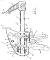
- FIGS. 1 to 3 show a clamping tool 1 with a support 3 to which a stationary jaw 5 is firmly connected and a push or pull rod 7 is held displaceable in the longitudinal direction of the push or pull rod 7.
- a push or pull rod 7 At one end of the push or Pull rod 7 is releasably attached to an arm 9, at the end of a fixed jaw 5 diametrically opposed movable jaw 11 is fixed, with the movable jaw 11 moves to the stationary jaw 5 by displacement of the push or pull rod 7. If the arm 9 is arranged to hold the clamping jaw 11 at the other end of the push or pull rod 7, the function of a spreading tool is obtained.
- the carrier 3 forms a housing in which at least partially components of a step transmission are housed.
- An actuating lever 13 extends from an actuating side 15 of the push or pull rod through a housing wall of the carrier 3 through a clamping side 17 of the push or pull rod 7 and is pivotally mounted by a pivot joint 19 on the carrier 3.
- an operator grips the handle 21 with her palm and with her fingers the actuating arm 13 and pulls the actuating lever 13 to the handle to carry out an actuating stroke.
- the actuating lever 13 comprises an active arm 23 which is in constant contact with a gear mechanism 26 in the form of a driver 25, which is formed of three steel plates arranged parallel to one another.
- a recorded in a blind hole 27 compression coil spring 29 forces the driver 25 while exerting a torque about a force input point 31 of the active arm 23 around in a relation to the push or pull rod 7 tilted position, so that a displacement of the push or pull rod 7 against the clamping direction S. is prevented, so a barrier effect is generated.
- the ratio of Betrelinshebelarm w b by the distance of an operating range of the operator on Actuating lever 13 is defined to the pivot joint 19, the Wirkhebelarm w w results and with which short feeds of the push or pull rod 7 in the clamping direction S can be realized at a Betreli Trent and thus very high clamping forces up to 1000 Newton between the jaws 5, 11 are reached when clamping a workpiece, not shown.
- the lever ratio is 10: 1.
- the driver 25 and the plate lock 33 serve to obtain the clamping forces acting on the workpiece.
- the clamping tool 1 has an unlocking device which can be actuated by a lever 3 (40) which is articulated on the carrier 3.
- the unlocking device 41 comprises in addition to the trigger lever 39 is a substantially parallel to the push or pull rod 7 extending plunger 43 which is fixedly mounted on the trigger lever 39 and extends through the plate lock 33 through or past the latter to the canted driver 25.
- a compression spring 45 has the task to spend the release lever 39 in a passive position.
- the unlocking device is designed to solve the locking effects of the blocking components (25, 33) successively upon actuation of the trigger lever 39, wherein preferably here first the blocking effect of the tilted driver 25 and then the blocking effect of the plate lock 33 is released. This is according to the execution of the FIGS. 1 to 3 achieved in that the distance of the plunger 43 is tuned by the driver on the pivot angle distance between the plate lock 33 and a plate lock 33 near portion of the trigger lever 39.
- the release lever 39 is actuated approximately halfway through its actuation stroke.
- the driver 25 facing the end of the plunger 43 comes into contact with the lying on the actuating side 15 portion of the driver 25 and pivots the driver 25 to the force input point 31 from its tilted position in a substantially to the push or pull rod 7 vertical position, in which would be the push or pull rod through the driver against the clamping direction S displaced.
- the released forces are derived in the housing by elastic deformation of housing parts. In this position, however, a displacement of the push or pull rod against the clamping direction S is not possible because it is hindered by the still existing blocking effect of the locking plates 33, which still maintains at least a portion of the clamping forces between the jaws. Consequently, the operator experiences no explosive release forces when first releasing the locking action of the driver 25.
- Fig. 3 is the trigger lever 39 is fully actuated, so that a portion of the tension-side portion of the trigger lever 39 comes into engagement in the region of the tension-side end of the plate lock 33 and thus the plate lock 33 is pivoted to release the jam and the clamping forces. Due to the distance between the point of engagement of the trigger lever 39 and the compression spring 35 only a small force must be expended to unlock, even if high clamping forces prevail.
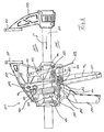
- FIGS. 4 to 6 a further embodiment is shown, for better readability of the figure description for identical and similar components for execution according to the FIGS. 1 to 3 the same reference numerals are used, which are increased by 100.
- the clamping tool 101 differs from the clamping tool 1 according to the FIGS. 1 to 3 in that the lock or plate lock 133 is not brought by means of a seated in a receptacle compression spring in the tilted position, but by means of a tension spring, the held at one end by the carrier and engages at the other end in a hole in the plate lock 133.
- Another distinguishing feature is the arrangement of a compression spring 145, which has the task to spend the release lever 139 in a passive position. In the execution according to the FIGS. 4 to 6 the compression spring 145 is not supported on the plate lock 139 but on the carrier 103.
- the plunger 143 does not come into contact with the cam 125 of the gear mechanism 126 at its end, but the plunger 143 is provided with a projecting projection 151 projecting toward the push rod, which can releasably engage the operating side portion of the cam 125 with its canting.
- clamping tool has a step gear, with the even higher clamping forces than with the clamping tool according to the FIGS. 1 to 3 can be caused because the Wirkhebelarm w w with respect to the Betchanistshebelarm w b is even smaller and thus very favorable leverage ratios of 12: 1 to produce high clamping forces.
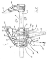
- FIG. 7 an embodiment of a clamping and / or spreading tool according to the invention is shown, for better readability of the figure description for identical or similar components to the embodiments according to the FIGS. 1 to 6 the same reference numerals are used, which are increased by 100 and 200, respectively.
- the clamping tool 202 differs from the previously described embodiments essentially in that a different lock or plate lock 233 and a different unlocking device 241 are provided.
- the plate lock 233 comprises two plates 232, which are tilted by a schematically indicated positive means in the form of a compression spring 235 relative to the push or pull rod.
- a compression spring 235 By the compression spring 235, the plates 232 of the plate lock 233 are pivoted about a stationary on the carrier 203 of the clamping tool 202 stop 261, which lies on the clamping side 217 of the push or pull rod 207.
- the stop 261 is at the same level with respect to the push rod 207 as the force input point 231 of the operating lever 213 about which the follower 225 is the transmission mechanism 226 be pivoted due to a compression coil spring not shown.
- the unlocking device according to the invention 241 comprises a parallel to the push or pull rod 207 displaceable plunger 243.
- the plunger 243 comprises two protrusions 263, 265, which cooperate entkantend upon actuation of the unblocking device 241 with the plates 232 and the driver 225, the latter against the effect the respective coercive agent are swung back.
- the unlocking device 241 is shown in two operating states, wherein the unactuated operating state is illustrated by solid lines, while the actuated state, ie the release of the blocking effects of the plate lock 233 and the tilted driver 225, is shown by dashed lines.
- the plunger 243 moves in the clamping direction S.
- the projections 263 and 265 respectively to the plates 233 and Drivers arranged that the blocking effect of the plate lock and the transmission mechanism 226 is canceled substantially simultaneously.
- the simultaneous cancellation of the blocking effects is structurally realized in that the distance between the projections 263 and 265 in the clamping direction S to the plates 232 of the plate lock 233 and to the drivers 225 of the transmission mechanism 226 is substantially equal.
- FIG. 8 a further embodiment of a clamping tool according to the invention is shown, wherein for better readability of the figure description for identical and similar components to the embodiments according to the FIGS. 1 to 7 the same reference numerals are used, which are increased by 100, 200 and 300, respectively.
- the clamping tool 301 differs in particular from the clamping tool 201 according to the FIG. 7 in that the disk lock 333 and the unlocking device 341 are made different.
- the plate lock 333 comprises two compression means 371 and 373 designed to cause a pivoting of the plates 332 around the stationary stopper 361 around.
- the compression spring 371 on the clamping side 317 of the push or pull rod 307 causes a secure tilting of the plates 332 relative to the push rod 307, whereby a reliable non-return lock for the push rod 397 is ensured.
- the compression spring 373 on the actuation side 315 of the push or pull rod 307 prevents Mitverlagem the plates 332 of the plate lock 333 as soon as the transmission mechanism 326 is actuated via the actuating lever 313 and the push or pull rod 307 is displaced in the clamping direction S.
- the plates 332 thus always remain in contact with the stop 361.
- the unlocking device 341 includes only a single projection 375, which with the canted drivers 325 of the transmission mechanism 326, the blocking effect in a lifting manner can come as soon as the release lever 339 of the unlocking device 341 is pressed accordingly strong.
- the projection 375 also serves as a stop for a compression spring 345, which pushes the plunger 343 back into its passive starting position, the in FIG. 8 is shown.
- the simultaneity of the Sperr Obersaufhebung is achieved in that the distance of the release lever to the plates 332 and the projection 375 to the drivers 325 is substantially equal.
Description
Die Erfindung betrifft ein Spann- und/oder Spreizwerkzeug mit einer Schub- oder Zugstange.The invention relates to a clamping and / or spreading tool with a push or pull rod.
Die Schub- oder Zugstange ist an einem Träger des Spann- und/oder Spreizwerkzeugs verlagerbar gehalten. Das Spann- und/oder Spreizwerkzeug hat eine ortsfeste Backe, die fest mit dem Träger verbunden ist, und eine an der Schub- oder Zugstange fest angebrachte bewegliche Spannbacke, die durch Verlagerung der Schub- oder Zugstange relativ zur ortsfesten Backe bewegt werden kann.The push or pull rod is held displaceable on a support of the clamping and / or spreading tool. The clamping and / or spreading tool has a stationary jaw, which is fixedly connected to the carrier, and a fixed to the push or pull rod movable jaw, which can be moved by displacement of the push or pull rod relative to the fixed jaw.
Zum Verlagern der Schub- oder Zugstange und der damit beweglichen Backe ist ein Schrittgetriebe vorgesehen, das einen Betätigungshebel, der an dem Träger schwenkbar gelagert ist, und einen durch den Betätigungshebel an der Schub- oder Zugstange verkantbaren Mitnehmer aufweist. Das Schrittgetriebe ist dazu ausgelegt, den Hub des Betätigungshebels in einen Vorschub der Schub- oder Zugstange umzuwandeln.To move the push or pull rod and the movable jaw with a step mechanism is provided which has an actuating lever which is pivotally mounted on the carrier, and a tiltable by the actuating lever on the push or pull rod driver. The indexer is designed to convert the stroke of the actuating lever into a feed of the push or pull rod.
Zum Einspannen eines Werkstücks wird die Schub- oder Zugstange über den verkanteten Mitnehmer zur festen Backe hin und zum Erzeugen von Spreizkräften von der festen Backe weg verlagert. Eine Sperre verhindert das Zurückgleiten der Schub- oder Zugstange.For clamping a workpiece, the push or pull rod is displaced over the tilted driver towards the fixed jaw and for generating spreading forces away from the fixed jaw. A lock prevents sliding back of the push or pull rod.
Ein derartiges sich in der Vergangenheit bewährtes Spann- und/oder Spreizwerkzeug ist aus der
Bei Spannwerkzeugen, mit denen Spannkräfte von über 1000 Newton erzeugt werden sollen, kann es zu einer Irritation und sogar zu einer Verletzung der Bedienperson durch die beim Freigeben der Spannkräfte impulsartig vorschnellende Schub- oder Zugstange entgegen der Vorschubrichtung kommen.When clamping tools with which clamping forces of over 1000 Newton are to be generated, it can lead to irritation and even injury to the operator by the release of the clamping forces impulsively vorschnellende push or pull rod against the feed direction.
Aus der
Ein Spann- oder Spreizwerkzeug, welches die Hebelverhältnisse eines langen Betätigungshebels zu einer nahe am Schwenkpunkt des Hebels angebrachten Stange ausnützt, um hohe Spannkräfte und einen großen Vorschub zu erzielen, ist aus der
Aus de
Es ist Aufgabe der Erfindung, ein Spann- und/oder Spreizwerkzeug zu entwickeln, bei dem der Kraftaufwand zum Lösen einer Rückdrücksperre reduziert ist.It is an object of the invention to develop a clamping and / or spreading tool in which the force required to release a back pressure lock is reduced.
Diese Aufgabe wird durch das Spann- und/oder Spreizwerkzeug gemäß Anspruch 1 gelöst.This object is achieved by the clamping and / or spreading tool according to claim 1.
Danach ist bei dem erfindungsgemäßen Spann- und/oder Spreizwerkzeug wenigstens eine Sperre vorgesehen, die eine Verlagerung entgegen einer Spann- und/oder Spreizrichtung dadurch sperrt, daß sie durch wenigstens ein Zwangsmittel, wie eine Feder, insbesondere Schraubenfeder, gegenüber der Zug- oder Schubstange verkantet ist. Durch die Verkantung der wenigstens einen Sperre mit der Schubstange werden die an einem Werkstück angreifenden Spannkräfte gehalten. Bei Betätigung einer Entsperreinrichtung wird die Sperre gelöst.Thereafter, at least one lock is provided in the clamping and / or spreading tool according to the invention, the displacement against a clamping and / or spreading direction characterized locks that it is tilted by at least one coercive means, such as a spring, in particular coil spring, against the pull or push rod. By tilting the at least one lock with the push rod, the forces acting on a workpiece clamping forces are held. Upon actuation of an unlocking the lock is released.
Bei dem Erfindungsaspekt ist wenigstens eine Platte der Sperre zur Ausbildung der gewünschten Verkantung gegenüber der Schub- oder Zugstange durch ein Zwangsmittel um eine gegenüber einem die Schub- oder Zugstange verschiebbar lagernden Träger des Spann- und/oder Spreizwerkzeugs ortsfeste Anlagestelle geschwenkt. Die ortsfeste Anlagestelle kann auf der Spannseite der Schub- oder Zugstange positioniert sein. Die ortsfeste Anlagestelle, um welche die wenigstens eine Platte der Sperre zur Ausbildung der Verkantung geschwenkt ist, und eine weitere Anlagestelle, um welche wenigstens eine Mitnehmerplatte des Getriebemechanismus aufgrund eines Zwangsmittels, wie einer Druckfeder, zur Ausbildung einer Verkantung mit der Schub- oder Zugstange geschwenkt ist, sind im wesentlichen auf demselben Niveau bezüglich der Schub- oder Zugstange angeordnet.In the aspect of the invention, at least one plate of the barrier for forming the desired tilting relative to the push or pull rod is pivoted by a positive means about a support of the clamping and / or spreading stationary support point displaceably mounted on a push or pull rod. The fixed contact point can be positioned on the tension side of the push or pull rod. The stationary abutment point about which the at least one plate of the lock is pivoted to form the tilting, and another abutment point about which at least one drive plate of the transmission mechanism due to a coercive means, such as a compression spring, pivoted to form a jamming with the push or pull rod are arranged at substantially the same level with respect to the push or pull rod.
Um den Kraftaufwand zum Lösen der Sperre zu reduzieren, sind vorzugsweise das Zwangsmittel und die Entsperreinrichtung derart aufeinander abgestimmt, daß sie mit der Sperre funktionsgemäß auf gegenüberliegenden Seiten der Schub- oder Zugstange in Eingriff kommen, nämlich das Zwangsmittel zum Verkanten der Sperre und die Entsperreinrichtung zur Lösung der Sperrwirkung der verkanteten Sperre. Mit der erfindungsgemäßen Maßnahme Bedienpersonenein großer bedienfreundlicher Betätigungshebel zum Lösen der Sperre zur Verfügung gestellt werden. Zum einen wird erfindungsgemäß erreicht, daß die Entsperreinrichtung entfernt von der Krafteintrittsstelle des Zwangsmittels mit der Sperre in Eingriff kommt, zum anderen, daß der Eingriffspunkt der Entsperreinrichtung entfernt von der Verkantung der Sperre und der Schub- oder Zugstange realisiert ist.In order to reduce the effort to release the lock, preferably the coercive means and the unblocking device are adapted to each other in such a way that they functionally engage with the lock on opposite sides of the push or pull rod, namely the positive means for tilting the lock and the unlocking device Solution of the blocking effect of the tilted barrier. With the measure according to the invention, a large, user-friendly operating lever for releasing the lock can be made available to operators. Firstly, it is achieved according to the invention that the unlocking device comes into engagement with the barrier remote from the force entry point of the coercive means, and secondly that the point of engagement of the unlocking device is realized away from the tilting of the barrier and the push or pull rod.
Das Zwangsmittel kann auf der Betätigungsseite der Schub- oder Zugstange und die Entsperreinrichtung kann auf der Spannseite der Schub- oder Zugstange mit der Sperre in Eingriff kommen. Eine besonders einfache bauliche Maßnahme zum Verkanten der Sperre gegenüber der Zugstange kann dadurch realisiert werden, daß die Sperre durch das Zwangsmittel um einen ortsfesten Punkt geschwenkt ist, der auf derjenigen Seite der Schub- und/oder Zugstange liegt, die der Seite gegenüberliegt, an der der Eingriffspunkt der Entsperreinrichtung liegt.The coercive means may be on the actuation side of the push or pull rod and the unlocking device can engage on the tension side of the push or pull rod with the lock. A particularly simple structural measure for tilting the lock against the pull rod can be realized that the lock by the coercive means a fixed point is pivoted, which lies on that side of the push and / or pull rod, which is opposite to the side at which the engagement point of the unblocking device is located.
Bei einer alternativen bevorzugten Ausführung der Erfindung kommen das die Verkantung der Sperre bewirkende Zwangsmittel auf der Spannseite der Schub- oder Zugstange und die die Verkantung aufhebende Entsperreinrichtung auf der Betätigungsseite der Schub- oder Zugstange mit der Sperre in Eingriff.In an alternative preferred embodiment of the invention, the wedging effect of the lock causing means on the tension side of the push or pull rod and the tilt canceling unlocking come on the operating side of the push or pull rod with the lock in engagement.
Bei einer Weiterbildung des obengenannten Erfindungsaspekts sind zwei Zwangsmittel, wie zwei Druckfedern, für eine der wenigstens einen Sperre vorgesehen. Ein derartiges Zwangsmittelpaar, das die Sperre in einer verkanteten Stellung bezüglich der Schub- oder Zugstange hält und eine Zurückverlagerung der Schub- oder Zugstange zuverlässig unterbindet, bewirkt auch, daß bei Betätigung des Schrittgetriebes des Spann- und/oder Spreizwerkzeugs, also bei einer Verlagerung der Schub- oder Zugstange in Spann- und/oder Spreizrichtung, eine unerwünschte Mitverlagerung der Sperre verhindert wird. Dabei sind ein erstes Zwangsmittel auf der Betätigungsseite der Schub- oder Zugstange und ein zweites Zwangsmittel auf der Spannseite der Schub- oder Zugstange angeordnet. Es stellte sich überraschenderweise heraus, daß das Zwangsmittel, das insbesondere einem ortsfesten Schwenkpunkt der Sperre naheliegt, eine sichere Verkantung der Sperre leistet, während das entfernt zum ortsfesten Schwenkpunkt liegende Zwangsmittel hauptsächlich die Mitverlagerung der Sperre bei Betätigung des Schrittgetriebes des Spann- und/oder Spreizwerkzeugs unterbindet.In a further development of the above aspect of the invention, two coercive means, such as two compression springs, are provided for one of the at least one barrier. Such Zwangsmittelpaar that holds the lock in a tilted position relative to the push or pull rod and reliably prevents a shift back of the push or pull rod, also causes when operating the indexer of the clamping and / or spreading tool, ie at a displacement of Push or pull rod in the clamping and / or spreading direction, an unwanted Mitlegagerung the lock is prevented. In this case, a first coercive means are arranged on the actuation side of the push or pull rod and a second coercive means on the tension side of the push or pull rod. It turned out, surprisingly, that the coercive means, in particular a fixed pivot point of the lock naheliegt, provides a secure tilting of the lock, while the remote to the fixed pivot coercive means mainly Mitlegagerung the lock on actuation of the indexer of the clamping and / or spreading tool in derogation.
Um nur geringe Bedienkräfte notwendig zu machen, eine einfache Bedienung zu gewährleisten und vor allem ein explosionsartiges Freisetzen der Spannkräfte zu vermeiden, besteht eine bevorzugte Ausgestaltung der Erfindung darin, daß bei dem erfindungsgemäßen Spannwerkzeug die Verlagerung der Schub- oder Zugstange entgegen einer Spann- und/oder Spreizrichtung durch einen Getriebemechanismus zum Verlagern in Spann- und/oder Spreizrichtung und durch eine vom Getriebemechanismus unabhängige Sperre gesperrt ist. Eine Entsperreinrichtung ist dazu ausgelegt, bei deren Betätigung die Sperrwirkung des Getriebemechanismus und der Sperre aufzuheben.To make only small operating forces necessary to ensure easy operation and especially to avoid an explosive release of the clamping forces, a preferred embodiment of the invention is that in the clamping tool according to the invention, the displacement of the push or pull rod against a clamping and / or spreading direction is locked by a gear mechanism for displacing in the clamping and / or spreading direction and by an independent from the gear mechanism lock. An unlocking device is designed to lift the blocking effect of the transmission mechanism and the lock when actuated.
Die Entsperreinrichtung kann dazu ausgelegt sein, bei deren Betätigung die Sperrwirkung des Getriebemechanismus und der Sperre im wesentlichen gleichzeitig aufzuheben. Alternativ kann vorgesehen sein, daß die Entsperreinrichtung dazu ausgelegt ist, die Sperrwirkung des Getriebemechanismus und der Sperre nacheinander, insbesondere die Sperrwirkung des Getriebemechanismus vor der Sperrwirkung der Sperre, aufzuheben. Bei der sukzessiven Aufhebung der sperrenden Verkantung kann die Entsperreinrichtung dazu ausgelegt sein, in einer vorbestimmten schrittweisen Entsperrabfolge auf den Getriebemechanismus und die Sperre einzuwirken.The unlocking device can be designed to cancel the blocking effect of the gear mechanism and the lock substantially simultaneously when actuated. Alternatively it can be provided that the unblocking device is designed to cancel the blocking effect of the transmission mechanism and the lock successively, in particular the blocking effect of the transmission mechanism before the blocking effect of the lock. In the successive cancellation of the locking canting, the unlocking device may be adapted to act on the gear mechanism and the lock in a predetermined stepwise unlocking sequence.
Durch das Vorsehen von zwei Sperren, nämlich durch den Getriebemechanismus, der ein Verlagern der Schub- oder Zugstange in Vorschubrichtung, nämlich in Spann- und/oder Spreizrichtung, zuläßt, aber ein Zurückverlagern der Schub- oder Zugstange insbesondere dann automatisch sperrt, wenn der Getriebemechanismus nicht von der Bedienperson betätigt wird, und durch eine separate Sperre, d.h. eine von dem Betrieb des Getriebemechanismus unabhängige Sperre, können sehr viel höhere Spannkräfte zwischen den Backen gehalten werden, als es bei den bekannten Spann- und/oder Spreizwerkzeug mit nur einer Sperre der Fall ist.By the provision of two locks, namely by the gear mechanism, which allows a displacement of the push or pull rod in the feed direction, namely in clamping and / or spreading direction, but a shift back of the push or pull rod in particular automatically locks when the transmission mechanism is not operated by the operator, and by a separate lock, ie independent of the operation of the transmission mechanism lock, much higher clamping forces can be held between the jaws, as is the case with the known clamping and / or spreading tool with only one lock.
Aufgrund der Maßnahme muß nur wenig Kraft aufgewendet werden, um die Sperrwirkungen zu lösen. Es stellte sich dabei als besonders vorteilhaft heraus, zuerst die Sperrwirkung des Getriebemechanismus und anschließend die der Sperre zu lösen.Due to the measure, only a small amount of force has to be expended in order to release the blocking effects. It turned out to be particularly advantageous to first solve the blocking effect of the transmission mechanism and then the lock.
Die Sperrwirkung des Getriebemechanismus kann dadurch hervorgerufen werden, daß ein Mitnehmer zum Verlagern der Spann- und/oder Spreizrichtung durch ein Zwangsmittel stets verkantet wird, d.h. auch im unbetätigten Zustand des Betätigungshebels, wobei das Zwangsmittel und der Mitnehmer derart aufeinander abgestimmt sind, daß nach einem Betätigungshub und während des Zurückgleitens eines Betätigungshebels des Getriebemechanismus keine Verkantung des Mitnehmers gegenüber der Schub- oder Zugstange besteht. Durch die Verkantung des Mitnehmers wird erreicht, daß kein Betätigungshubverlust des Betätigungsarms hingenommen werden muß. Außerdem verhindert auch die Verkantung des Mitnehmers, daß sich die Schub- oder Zugstange im Ruhezustand des Getriebemechanismus entgegen der Vorschubrichtung verlagert.The blocking effect of the transmission mechanism can be caused by a driver for displacing the clamping and / or spreading direction is always tilted by a force means, ie even in the unactuated state of the actuating lever, wherein the coercive means and the driver are coordinated such that after a Actuating and during the slipping back of an operating lever of the transmission mechanism is no tilting of the driver relative to the push or pull rod. By tilting the driver is achieved that no Betätigungshubverlust the actuating arm must be accepted. In addition, the tilting of the driver prevents that the push or pull rod displaced in the rest state of the transmission mechanism against the feed direction.
Um die gewünschte Abfolge des Entsperrens zu realisieren, kann vorzugsweise die Sperre mehrteilig ausgeführt sein, nämlich dadurch, daß eine Sperrplatte durch ein Zwangsmittel in eine stets verkantete Position gegenüber der Schub- oder Zugstange gebracht wird, so daß eine Verlagerung entgegen der Vorschubrichtung der Schub- oder Zugstange verhindert wird und die zwischen den Spannbacken erzeugten Spannkräfte gespeichert werden. Vorzugsweise ist das Zwangsmittel eine Feder, vorzugsweise eine Schraubenfeder, die als Druckfeder bzw. als Zugfeder ausgeführt sein kann und einerseits an der Sperrplatte angreift und andererseits sich an dem Träger abstützt oder vom Träger gehalten wird.In order to realize the desired sequence of unlocking, preferably, the lock can be made in several parts, namely the fact that a locking plate is brought by a positive means in a always tilted position relative to the push or pull rod, so that a displacement against the feed direction of the thrust or pull rod is prevented and the clamping forces generated between the jaws are stored. Preferably, the coercive means is a spring, preferably a coil spring, which may be designed as a compression spring or as a tension spring and on the one hand acts on the blocking plate and on the other hand is supported on the carrier or held by the carrier.
Die Entsperreinrichtung kann einen Entsperrhebel vorsehen, der erfindungsgemäß mit der Sperre lösend in Eingriff kommen kann. Dabei kann eine dritte Sperreinrichtung dadurch realisiert werden, daß der Entsperrhebel auf die gleiche Weise wie der Mitnehmer über ein Zwangsmittel in eine gegenüber der Schub- oder Zugstange verkantete Stellung verbracht wird. Zum Lösen der dreifachen Sperre kann die Entsperrabfolge dadurch definiert sein, daß zuerst die Sperrwirkung des Entsperrhebels gelöst wird.The unlocking device may provide an unlocking lever, which according to the invention can be releasably engaged with the lock. In this case, a third locking device can be realized that the release lever is spent in the same manner as the driver via a positive means in a relation to the push or pull rod tilted position. To release the triple lock, the unlocking sequence can be defined by first releasing the locking action of the unlocking lever.
Besonders geringe Freigabekräfte und eine besonders gute Spannkraftableitung von dem einzuspannenden Werkstück werden dadurch erreicht, daß die Entsperreinrichtung an dem verkanteten Mitnehmer des Getriebemechanismus und an der verkanteten Sperre auf jeweils gegenüberliegenden Seiten, nämlich der Spannseite oder der Betätigungsseite, der Schub- oder Zugstange die die Sperrwirkung realisierende Verkantung aufhebend in Eingriff kommt.Particularly low release forces and a particularly good clamping force dissipation of the workpiece to be clamped are achieved in that the unblocking device on the tilted driver of the transmission mechanism and the tilted lock on opposite sides, namely the clamping side or the actuating side of the push or pull rod which the blocking effect realizing tilting reversely engages.
Geringe Freigabekräfte sind auch dann ausreichend, wenn die Entsperreinrichtung auf den Mitnehmer des Getriebemechanismus und auf die Sperre an der einer Angriffsstelle des jeweiligen Zwangsmittels gegenüberliegenden Seite der Schub- oder Zugstange wirkt. Ist beispielsweise das Zwangsmittel auf der Spannseite angeordnet, das ein Moment hervorruft, um den Mitnehmer oder die Sperre in die verkantete Position zu schwenken, wirkt die Entsperreinrichtung diesem Moment auf der gegenüberliegenden Seite mittels eines großen Entsperrhebelarms entgegen. Zum Entsperren wird der verkantete Mitnehmer oder die verkantete Sperre um den Angriffspunkt des Zwangsmittels herum zurück geschwenkt.Low release forces are sufficient even if the unblocking device acts on the driver of the transmission mechanism and on the lock on the opposite side of the push or pull rod to an attack point of the respective force means. For example, if the positive means on the tension side arranged, which causes a moment to pivot the driver or the lock in the tilted position, the unlocking counteracts this moment on the opposite side by means of a large Entsperrhebelarms. To unlock the tilted driver or the tilted lock is pivoted back around the point of the coercive agent around.
Der Getriebemechanismus zum Verlagern der Schub- oder Zugstange in Spann- oder Spreizrichtung kann dazu ausgelegt sein, hohe Spannkräfte zu erzeugen. Dafür kann der Getriebemechanismus einen Betätigungsarm aufweisen, der auf einer Spannseite der Schub- oder Zugstange schwenkbar gelagert ist und auch auf der Spannseite mit dem Mitnehmer kraft-übertragungsgemäß in Eingriff steht.The transmission mechanism for displacing the push or pull rod in the clamping or spreading direction can be designed to generate high clamping forces. For this, the transmission mechanism may comprise an actuating arm which is pivotally mounted on a clamping side of the push or pull rod and also on the tension side with the driver force-transmission in engagement.
Die Sperre kann dazu ausgelegt sein, sich an einem ortsfesten Punkt des Spann- und/oder Spreizwerkzeugs, insbesondere einem Anschlag des die Schub- oder Zugstange verschiebbar lagernden Trägers, auf einer Spannseite der Schub- oder Zugstange abzustützen.The barrier may be designed to be supported on a fixed side of the clamping and / or spreading tool, in particular a stop of the carrier displaceably mounted on the push or pull rod, on a tension side of the push or pull rod.
Die Entsperreinrichtung kann einen Auslösehebel oder Sperrhebel aufweisen, mit dem ein Bauteil zur Übertragung der Betätigungsbewegung des Auslösehebels gekoppelt ist, welches Bauteil bei Betätigung des Auslösehebels auf den Getriebemechanismus und die Sperre entsperrend einwirkt. Bei der Ausführung der Entsperreinrichtung kann der Auslösehebel auf die Sperre die Verkantung direkt aufhebend einwirken, während die Verkantung des Getriebemechanismus über das Bauteil zur Übertragung der Betätigungsbewegung aufgehoben wird.The unlocking device may comprise a release lever or locking lever, with which a component for transmitting the actuating movement of the release lever is coupled, which component acts releasably upon actuation of the release lever on the transmission mechanism and the lock. In the embodiment of the unblocking device, the release lever can act on the lock directly reversing the canting, while the canting of the transmission mechanism is canceled via the component for transmitting the actuating movement.
Das Bauteilteil kann als federvorgespannter Stab ausgeführt sein, der insbesondere in Längsrichtung verschiebbar gelagert ist.The component part may be designed as a spring-biased rod, which is mounted in particular displaceable in the longitudinal direction.
Der Auslösehebel kann an einem die Schub- oder Zugstange verschiebbar lagernden Träger angelenkt sein, wobei die Gelenkstelle des Auslösehebels im wesentlichen auf Höhe der Schub- oder Zugstange angeordnet ist.The release lever may be articulated to a carrier displaceably supporting the push or pull rod, wherein the hinge point of the release lever is arranged substantially at the level of the push or pull rod.
Weitere Vorteile, Merkmale und Eigenschaften der Erfindung werden durch die folgende Beschreibung bevorzugter Ausführungen anhand der beiliegenden Zeichnungen deutlich, in denen zeigen:
- Fig. 1
- eine Seitenansicht einer Ausführung eines Spann- und/oder Spreizwerkzeugs in einem ersten Betriebszustand, in welchem die Verlagerung der Schub- oder Zugstange entgegen der Spannrichtung S gesperrt ist;
- Fig. 2
- die Ausführung gemäß
Fig. 1 in einem zweiten Zustand, bei dem eine Sperrwirkung des Getriebemechanismus gelöst ist und die Sperrwirkung der Sperre besteht; - Fig. 3
- die Ausführung gemäß
Fig. 1 und2 in einem dritten Betriebszustand, bei dem sowohl die Sperrwirkung der Getriebemechanismus als auch die der Sperre gelöst sind; - Fig. 4
- eine Ausführung eines Spann- und/oder Spreizwerkzeugs mit einem offen dargestellten Funktionsgehäuse in einem ersten Betriebszustand, bei dem eine Verlagerung der Schub- oder Zugstange in Spannrichtung S gesperrt ist;
- Fig. 5
- die Ausführung gemäß
Fig. 4 in einem zweiten Betriebszustand, bei dem die Sperrwirkung des Getriebemechanismus aufgehoben ist, während die Sperrwirkung der Sperre besteht; - Fig. 6
- die Ausführung gemäß den
Figuren 4 und5 mit einem dritten Betriebszustand, bei dem sowohl die Sperrwirkung des Getriebemechanismus als auch die der Sperre auf gehoben sind; - Fig.7
- eine Seitenansicht einer erfindungsgemäßen Ausführung eines erfindungsgemäßen Spann- und/oder Spreizwerkzeugs mit einem offen dargestellten Funktionsgehäuse in einem unbetätigten Betriebszustand; und
- Fig. 8
- eine Seitenansicht einer erfindungsgemäßen Ausführung eines erfindungsgemäßen Spann- und/oder Spreizwerkzeugs mit einem offen dargestellten Funktionsteilgehäuse in einem unbetätigten Betriebszustand.
- Fig. 1
- a side view of an embodiment of a clamping and / or spreading tool in a first operating state in which the displacement of the push or pull rod against the clamping direction S is locked;
- Fig. 2
- the execution according to
Fig. 1 in a second state in which a locking action of the gear mechanism is released and the locking effect of the lock consists; - Fig. 3
- the execution according to
Fig. 1 and2 in a third operating state in which both the locking action of the gear mechanism and the lock are released; - Fig. 4
- an embodiment of a clamping and / or spreading tool with an open function housing shown in a first operating state in which a shift of the push or pull rod is locked in the clamping direction S;
- Fig. 5
- the execution according to
Fig. 4 in a second operating condition in which the locking effect of the transmission mechanism is canceled while the locking action of the lock exists; - Fig. 6
- the execution according to the
FIGS. 4 and5 with a third operating state in which both the locking action of the transmission mechanism and the lock are lifted; - Figure 7
- a side view of an inventive embodiment of a clamping and / or spreading tool according to the invention with an open function housing shown in an unactuated operating condition; and
- Fig. 8
- a side view of an embodiment according to the invention of a clamping and / or spreading tool according to the invention with an open function part housing shown in an unactuated operating condition.
Die
Der Träger 3 bildet ein Gehäuse, in dem zumindest teilweise Komponenten eines Schrittgetriebes untergebracht sind.The
Ein Betätigungshebel 13 erstreckt sich von einer Betätigungsseite 15 der Schub- oder Zugstange durch eine Gehäusewand des Trägers 3 hindurch auf eine Spannseite 17 der Schub- oder Zugstange 7 und ist durch ein Schwenkgelenk 19 schwenkbar am Träger 3 angebracht ist. Beim Betätigen des Betätigungsarms 13 umgreift eine Bedienperson (nicht dargestellt) mit ihrer Handfläche den Griff 21 und mit ihren Fingern den Betätigungsarm 13 und zieht zum Ausführen eines Betätigungshubs den Betätigungshebel 13 zum Griff.An
Der Betätigungshebel 13 umfaßt einen Wirkarm 23, der im ständigen Kontakt mit einem in Form eines Mitnehmers 25 ausgebildeten Getriebemechanismus 26 steht, der aus drei parallel zueinander angeordneten Stahlplatten gebildet ist. Eine in einem Sackloch 27 aufgenommene Druckspiralfeder 29 zwingt den Mitnehmer 25 unter Ausübung eines Drehmoments um eine Krafteintragsstelle 31 des Wirkarms 23 herum in eine gegenüber der Schub- oder Zugstange 7 verkantete Stellung, so daß eine Verlagerung der Schub- oder Zugstange 7 entgegen der Spannrichtung S verhindert wird, also eine Sperrwirkung erzeugt ist.The actuating
Mit der Anordnung des Schwenkgelenks 19 und der Krafteintragsstelle 31 des Wirkarms 23 auf der Spannseite 17 der Schub- oder Zugstange7 kann für das Schrittgetriebe ein Hebelverhältnis geschaffen werden, das sich aus dem Verhältnis von Betätigungshebelarm wb, der durch den Abstand eines Betätigungsbereichs der Bedienperson am Betätigungshebel 13 zum Schwenkgelenk 19 definiert ist, zum Wirkhebelarm ww ergibt und mit welchem kurze Vorschübe der Schub- oder Zugstange 7 in Spannrichtung S bei einem Betätigungshub realisiert werden können und somit sehr hohe Spannkräfte bis über 1000 Newton zwischen den Spannbacken 5, 11 beim Einspannen eines nicht dargestellten Werkstücks erreichbar sind. Beispielsweise liegt das Hebelverhältnis bei 10:1.With the arrangement of the pivot joint 19 and the
Um ein Zurückverlagern der Schub- oder Zugstange 7 entgegen der Spannrichtung S zu verhindern, ist neben dem stets verkanteten Mitnehmer 25 eine in Form von Platten 32 gebildete Sperre oder Plattensperre 33 vorgesehen, deren Sperrwirkung mit Hilfe einer vom Träger 3 aufgenommenen Druckfeder 35 realisiert ist, welche die Plattensperre 33 mittels dem am Träger 3 ortsfesten Anschlag 37 in eine verkantete Stellung gegenüber der Schub- oder Zugstange 7 schwenkt.In order to prevent a shifting back of the push or pull
Wenn von einer Bedienperson ein Werkstück zwischen den Spannbacken 5 und 11 eingespannt werden soll und hohe Spannkräfte auf das Werkstück auszuüben sind, dienen der Mitnehmers 25 und die Plattensperre 33 dazu, die an den Werkstück angreifenden Spannkräfte zu erhalten.When a workpiece is to be clamped by an operator between the
Um ein Freigeben des Gegenstands ohne explosionsartige Bewegung der Schub- oder Zugstange 7 mit der Backe 11 zu realisieren, weist das Spannwerkzeug 1 eine Entsperreinrichtung auf, welche über einen am Träger 3 angelenkten (40) Auslösehebel 39 betätigbar ist. Die Entsperreinrichtung 41 umfaßt neben dem Auslösehebel 39 eine sich im wesentlichen parallel zur Schub- oder Zugstange 7 erstreckenden Stößel 43, der an dem Auslösehebel 39 fest angebracht ist und sich durch die Plattensperre 33 hindurch oder an letzterer vorbei hin zum verkanteten Mitnehmer 25 erstreckt. Eine Druckfeder 45 hat die Aufgabe, den Auslösehebel 39 in eine passive Stellung zu verbringen. Die Entsperreinrichtung ist dazu ausgelegt, bei Betätigung des Auslösehebels 39 die Sperrwirkungen der sperrenden Bauteile (25, 33) nacheinander zu lösen, wobei hier vorzugsweise zuerst die Sperrwirkung des verkanteten Mitnehmers 25 und anschließend die Sperrwirkung der Plattensperre 33 gelöst wird. Dies wird gemäß der Ausführung nach den
In den
In
In
Da ein Teil der Spannkräfte durch Lösen des Mitnehmers 25 bereits freigegeben sind, bewirkt das Lösen der Sperrung der Plattensperre 33 nur noch eine für die Bedienperson geringfügig bemerkbare Kraftableitung.Since a part of the clamping forces are already released by releasing the
In den
Das Spannwerkzeug 101 unterscheidet sich von dem Spannwerkzeug 1 gemäß den
Als weiteres Unterscheidungsmerkmal ist die Anordnung einer Druckfeder 145 zu erwähnen, welche die Aufgabe hat, den Auslösehebel 139 in eine passive Stellung zu verbringen. Bei der Ausführung gemäß den
Das Stößel 143 kommt mit dem Mitnehmer 125 des Getriebemechanismus 126 nicht an dessen Ende in Kontakt, vielmehr ist das Stößel 143 mit einem zur Schubstange hin vorstehenden mitnehmenden Vorsprung 151 versehen, der mit dem betätigungsseitigen Abschnitt des Mitnehmers 125 dessen Verkantung freigebend in Eingriff kommen kann.The
Wie in
Das in den
Die Ausführungen gemäß den
In
Das Spannwerkzeug 202 unterscheidet sich von den vorher beschriebenen Ausführungen im wesentlichen dadurch, daß eine unterschiedliche Sperre oder Plattensperre 233 und eine unterschiedliche Entsperreinrichtung 241 vorgesehen sind.The clamping tool 202 differs from the previously described embodiments essentially in that a different lock or
Die Plattensperre 233 umfaßt zwei Platten 232, die durch ein schematisch angedeutetes Zwangsmittel in Form einer Druckfeder 235 gegenüber der Schub- oder Zugstange verkantet werden. Durch die Druckfeder 235 werden die Platten 232 der Plattensperre 233 um einen am Träger 203 des Spannwerkzeugs 202 ortsfesten Anschlag 261 geschwenkt, der auf der Spannseite 217 der Schub- oder Zugstange 207 liegt.The
Um im wesentlichen gleiche Hebelverhältnisse zum Entsperren der Plattensperre 233 sowie des eine Sperrwirkung aufweisenden Getriebemechanismus 226 bereitzustellen, ist der Anschlag 261 auf demselben Niveau bezüglich der Schub- oder Zugstange 207 wie die Krafteintragsstelle 231 des Betätigungshebels 213, um welche die den Getriebemechanismus 226 bildenden Mitnehmer 225 aufgrund einer nicht näher dargestellten Druckspiralfeder geschwenkt werden.In order to provide substantially equal leverage for unlocking the
Die erfindungsgemäße Entsperreinrichtung 241 umfaßt einen parallel zur Schub- oder Zugstange 207 verlagerbaren Stößel 243. Der Stößel 243 umfaßt zwei Vorsprünge 263, 265, die bei Betätigung der Entsperreinrichtung 241 mit den Platten 232 bzw. dem Mitnehmer 225 entkantend zusammenwirken, indem letztere gegen die Wirkung des jeweiligen Zwangsmittels zurückgeschwenkt werden.The unlocking device according to the
Die Entsperreinrichtung 241 ist in zwei Betriebszuständen dargestellt, wobei der unbetätigte Betriebszustand durch durchgezogene Linien illustriert ist, während der betätigte Zustand, also das Lösen der Sperrwirkungen der Plattensperre 233 sowie der verkanteten Mitnehmer 225, punkt-strichliert dargestellt ist.The unlocking
Wird der Auslösehebel 239 um ein nicht näher dargestelltes Schwenkgelenk auf Höhe der Schub- oder Zugstange 207 hin zum Betätigungshebel 213 geschwenkt, verlagert sich der Stößel 243 in Spannrichtung S. Dabei sind die Vorsprünge 263 und 265 jeweils derart zu den Platten 233 bzw. zu den Mitnehmern angeordnet, daß die Sperrwirkung der Plattensperre sowie des Getriebemechanismus 226 im wesentlichen gleichzeitig aufgehoben wird. Die simultane Aufhebung der Sperrwirkungen wird strukturell dadurch realisiert, daß der Abstand der Vorsprünge 263 bzw. 265 in Spannrichtung S zu den Platten 232 der Plattensperre 233 bzw. zu den Mitnehmern 225 des Getriebemechanismus 226 im wesentlichen gleich groß ist.If the
In
Das Spannwerkzeug 301 unterscheidet sich insbesondere von dem Spannwerkzeug 201 gemäß der
Die Plattensperre 333 umfaßt zwei als Druckfedern 371 und 373 ausgebildete Zwangsmittel, welche ein Verschwenken der Platten 332 um den ortsfesten Anschlag 361 herum bewirken. Die Druckfeder 371 auf der Spannseite 317 der Schub- oder Zugstange 307 bewirkt ein sicheres Verkanten der Platten 332 gegenüber der Schubstange 307, wodurch eine zuverlässige Rückdrücksperre für die Schubstange 397 sichergestellt ist.The plate lock 333 comprises two compression means 371 and 373 designed to cause a pivoting of the
Die Druckfeder 373 auf der Betätigungsseite 315 der Schub- oder Zugstange 307 verhindert das Mitverlagem der Platten 332 der Plattensperre 333, sobald der Getriebemechanismus 326 über den Betätigungshebel 313 betätigt wird und die Schub- oder Zugstange 307 in Spannrichtung S verlagert wird. Die Platten 332 bleiben somit stets in Anlage an dem Anschlag 361.The
Die Entsperreinrichtung 341 umfaßt nur einen einzigen Vorsprung 375, der mit den verkanteten Mitnehmern 325 des Getriebemechanismus 326 deren Sperrwirkung aufhebend in Eingriff kommen kann, sobald der Auslösehebel 339 der Entsperreinrichtung 341 entsprechend stark betätigt ist.The unlocking
Der Vorsprung 375 dient auch als Anschlag für eine Druckfeder 345, welche den Stößel 343 zurück in dessen passive Ausgangsstellung drängt, die in
Bei Betätigung des Auslösehebels 339 wird der Stößel 343 in Spannrichtung S geschoben, wobei simultan die Sperrwirkung der Mitnehmer 325 sowie der Platten 332 aufgehoben wird. Die Aufhebung der Sperrwirkung der Sperre 333 wird unmittelbar durch das Ineingriffbringen des Auslösehebels 339 an dem unteren Ende der Platten 332 bewirkt.Upon actuation of the
Die Simultanität der Sperrwirkungsaufhebung wird dadurch erreicht, daß der Abstand des Auslösehebels zu den Platten 332 sowie des Vorsprungs 375 zu den Mitnehmern 325 im wesentlichen gleich groß ist.The simultaneity of the Sperrwirkungsaufhebung is achieved in that the distance of the release lever to the
- 1, 101, 201, 3011, 101, 201, 301
- Spannwerkzeugclamping tool
- 3, 103, 203, 3033, 103, 203, 303
- Trägercarrier
- 5, 105, 205, 3055, 105, 205, 305
- Backejaw
- 7, 107, 207, 3077, 107, 207, 307
- Zugstangepull bar
- 9, 1099, 109
- Armpoor
- 11, 11111, 111
- Spannbackejaw
- 13, 113, 213, 31313, 113, 213, 313
- Betätigungshebelactuating lever
- 15, 115, 215, 31515, 115, 215, 315
- Betätigungsseiteactuating side
- 17, 117, 217, 31717, 117, 217, 317
- Spannseiteclamping side
- 19, 119, 219, 31919, 119, 219, 319
- Schwenkgelenkpivot
- 21, 121, 22121, 121, 221
- GriffHandle
- 23, 12323, 123
- Wirkarmoperating arm
- 25, 125, 225, 32525, 125, 225, 325
- Mitnehmertakeaway
- 26, 126, 226, 32626, 126, 226, 326
- Getriebemechanismustransmission mechanism
- 27, 32727, 327
- Sacklochblind
- 29, 129, 32929, 129, 329
- DruckspiralfederCompression coil spring
- 32, 132, 232, 33232, 132, 232, 332
- Plattenplates
- 31, 131, 231, 33131, 131, 231, 331
- KrafteintragsstelleForce entry location
- 33, 133, 233, 33333, 133, 233, 333
- Plattensperre oder SperreDisk lock or lock
- 3535
- Druckfedercompression spring
- 37, 13737, 137
- Anschlagattack
- 39, 139, 239, 33939, 139, 239, 339
- Auslösehebelsear
- 40, 140, 34040, 140, 340
- Schwenkgelenk von AuslösehebelSwivel joint of release lever
- 41, 141, 241, 34141, 141, 241, 341
- Entsperreinrichtungunlocking
- 43, 143, 243, 34343, 143, 243, 343
- Stößeltappet
- 45, 145, 34545, 145, 345
- Druckfedercompression spring
- 151151
- Vorsprunghead Start
- 153153
- Aufbauchungbagging
- 155155
- Zugfedermainspring
- 261, 361261, 361
- ortsfester Anschlagfixed stop
- 263, 265263, 265
- Vorsprüngeprojections
- 371, 373371, 373
- Druckfedercompression spring
- 375375
- Vorsprunghead Start
- ww w w
- Wirkhebelarmactive lever arm
- wb w b
- Betätigungshebelarmactuating lever arm
- SS
- Spannrichtungtensioning direction
Claims (5)
- A clamping and/or spreading tool with a push or pull rod (207, 307), at least one lock (233, 333), which blocks a displacement of the push or pull rod (207, 307) contrary to a clamping and/or spreading direction (S) such that it is tilted by a coercive means, such as a spring, in particular a thrust spring, relative to the push or pull rod (207, 307), and an unlocking device (241, 341), which by the actuation of a release lever (239, 339) articulated on a carrier (203, 303) of the clamping and/or spreading tool (201, 301) releases the locking action of the lock (233, 333), wherein
at least one plate (232, 332) of the lock (233, 333), for purposes of being tilted with the push or pull rod (207, 307) mounted such that it can be moved on the carrier (203, 303), is pivoted by the coercive means about a point that is fixed in location relative to the carrier (203, 303), and wherein
the unlocking device (241, 341) interacts with the at least one plate (232, 332) so as to cancel the tilt,
characterised in that,
the fixed point, about which the plate of the lock (233, 333) is pivoted, and an attachment point, about which at least one driver plate of a gear mechanism (226, 326) is pivoted so that it is canted with respect to the push or pull rod (207, 307), are arranged essentially at the same height relative to the push or pull rod (207, 307). - The clamping and/or spreading tool in accordance with Claim 1,
characterised in that,
the coercive means and the unlocking device (241, 341) at least on opposing sides of the push or pull rod (207, 307) engage functionally with the lock (233, 333). - The clamping and/or spreading tool in accordance with Claim 1 or 2,
characterised in that,
the fixed point, about which the plate (232, 332) of the lock (233, 333) is pivoted, is determined on the clamping side (217, 317) of the push or pull rod (207, 307) on the carrier (203,303). - The clamping and/or spreading tool in accordance with Claim 1,
characterised in that,
the coercive means on a clamping side (317) of the push or pull rod (307), and the unlocking device (341) on an actuation side (315) of the push or pull rod (307), engage with the lock. - The clamping and/or spreading tool in accordance with one of the Claims 1 to 4,
characterised in that,
two coercive means are provided for purposes of canting the at least one lock, wherein
a first coercive means is arranged on the actuation side (315) of the push or pull rod (307) and a second coercive means is arranged on the clamping side (317) of the push or pull rod (307).
Priority Applications (1)
| Application Number | Priority Date | Filing Date | Title |
|---|---|---|---|
| EP11001103.8A EP2324958B1 (en) | 2004-05-19 | 2004-12-08 | Tensioning and/or widening tool with a push or pull bar |
Applications Claiming Priority (2)
| Application Number | Priority Date | Filing Date | Title |
|---|---|---|---|
| DE102004024862A DE102004024862A1 (en) | 2004-05-19 | 2004-05-19 | Clamping and / or spreading tool |
| EP04803645A EP1750905B1 (en) | 2004-05-19 | 2004-12-08 | Chucking and/or expansion tool having a push or pull rod |
Related Parent Applications (2)
| Application Number | Title | Priority Date | Filing Date |
|---|---|---|---|
| EP04803645.3 Division | 2004-12-08 | ||
| EP04803645A Division EP1750905B1 (en) | 2004-05-19 | 2004-12-08 | Chucking and/or expansion tool having a push or pull rod |
Related Child Applications (1)
| Application Number | Title | Priority Date | Filing Date |
|---|---|---|---|
| EP11001103.8 Division-Into | 2011-02-10 |
Publications (3)
| Publication Number | Publication Date |
|---|---|
| EP2085183A2 EP2085183A2 (en) | 2009-08-05 |
| EP2085183A3 EP2085183A3 (en) | 2009-10-07 |
| EP2085183B1 true EP2085183B1 (en) | 2013-02-13 |
Family
ID=34959880
Family Applications (3)
| Application Number | Title | Priority Date | Filing Date |
|---|---|---|---|
| EP04803645A Active EP1750905B1 (en) | 2004-05-19 | 2004-12-08 | Chucking and/or expansion tool having a push or pull rod |
| EP09002670A Expired - Fee Related EP2085183B1 (en) | 2004-05-19 | 2004-12-08 | Tensioning and/or widening tool with a push or pull bar |
| EP11001103.8A Expired - Fee Related EP2324958B1 (en) | 2004-05-19 | 2004-12-08 | Tensioning and/or widening tool with a push or pull bar |
Family Applications Before (1)
| Application Number | Title | Priority Date | Filing Date |
|---|---|---|---|
| EP04803645A Active EP1750905B1 (en) | 2004-05-19 | 2004-12-08 | Chucking and/or expansion tool having a push or pull rod |
Family Applications After (1)
| Application Number | Title | Priority Date | Filing Date |
|---|---|---|---|
| EP11001103.8A Expired - Fee Related EP2324958B1 (en) | 2004-05-19 | 2004-12-08 | Tensioning and/or widening tool with a push or pull bar |
Country Status (6)
| Country | Link |
|---|---|
| US (2) | US7896322B2 (en) |
| EP (3) | EP1750905B1 (en) |
| CN (2) | CN101027162B (en) |
| AU (1) | AU2004320073B2 (en) |
| DE (3) | DE102004024862A1 (en) |
| WO (1) | WO2005115690A1 (en) |
Families Citing this family (25)
| Publication number | Priority date | Publication date | Assignee | Title |
|---|---|---|---|---|
| GB2393414A (en) | 2001-08-10 | 2004-03-31 | American Tool Comp Inc | Increased and variable force and multi-speed clamps |
| EP2338641B1 (en) * | 2003-08-01 | 2015-06-17 | Irwin Industrial Tool Company | Stepping gear for a tensioning and/or spreading tool and tensioning and/or spreading tool |
| EP1704021B1 (en) | 2003-12-12 | 2011-04-20 | Irwin Industrial Tools GmbH | Clamping and/or splitting tool with a drive mechanism for continuous displacement of both clamping cheeks relative to one another |
| DE102004024862A1 (en) * | 2004-05-19 | 2006-01-05 | Irwin Industrial Tools Gmbh | Clamping and / or spreading tool |
| US8177203B2 (en) * | 2007-04-05 | 2012-05-15 | Stanley Black & Decker, Inc. | Clamp and lever therefor |
| US20090206534A1 (en) * | 2008-02-14 | 2009-08-20 | Mccracken Robert E | CamLock Clamp |
| SE532515C2 (en) * | 2008-06-02 | 2010-02-16 | Nederman Philip & Co Ab | Exhaust pipe gripping device |
| US8430383B2 (en) * | 2008-07-18 | 2013-04-30 | Irwin Industrial Tools Company | Clamp with a support |
| US8443499B2 (en) * | 2009-03-03 | 2013-05-21 | GM Global Technology Operations LLC | Concentric camshaft and method of assembly |
| US9289884B2 (en) * | 2011-01-31 | 2016-03-22 | Sajid Patel | Bar clamp |
| US9091113B2 (en) | 2011-02-21 | 2015-07-28 | Pilgrim Family Enterprises Llc | Safety gate |
| US8438741B2 (en) | 2011-08-05 | 2013-05-14 | Black & Decker, Inc. | Lock for power tool |
| US8882093B2 (en) * | 2012-04-05 | 2014-11-11 | Sheng Pu Promotion Co., Ltd. | Handheld clamping tool |
| US9676079B2 (en) * | 2013-03-11 | 2017-06-13 | Stanley Black & Decker, Inc. | Clamp |
| CN104070480B (en) | 2013-03-15 | 2018-06-22 | 创科电动工具科技有限公司 | clamping and expansion tool |
| US9211635B2 (en) * | 2013-08-01 | 2015-12-15 | Robert N. Poole | Self-adjusting bar clamp |
| USD771456S1 (en) | 2014-08-01 | 2016-11-15 | Milwaukee Electric Tool Corporation | Pliers with control key |
| US20160207175A1 (en) | 2015-01-15 | 2016-07-21 | Milwaukee Electric Tool Corporation | Locking pliers with improved adjustment member |
| USD769110S1 (en) * | 2015-03-10 | 2016-10-18 | Armin Joseph Altemus | Clamp for securing a ladder to fascia |
| USD782891S1 (en) | 2015-04-02 | 2017-04-04 | Milwaukee Electric Tool Corporation | Locking pliers |
| US10843605B2 (en) | 2018-05-10 | 2020-11-24 | Dorel Juvenile Group, Inc. | Headrest-height adjuster for juvenile seat |
| US20220281076A1 (en) | 2018-08-29 | 2022-09-08 | New Revo Brand Group, Llc | Ball joint system and support device |
| US11697525B2 (en) | 2018-09-28 | 2023-07-11 | Keith Cyzen | Removable collection container system for a work surface |
| CN110361593B (en) * | 2019-07-16 | 2021-08-10 | 国网山东省电力公司招远市供电公司 | Distribution network line loss analyzer |
| DE102022105002A1 (en) | 2022-03-03 | 2023-09-07 | Wolfcraft Gmbh | Device for the stepwise displacement of a push/pull rod |
Family Cites Families (61)
| Publication number | Priority date | Publication date | Assignee | Title |
|---|---|---|---|---|
| US4381105A (en) | 1980-05-08 | 1983-04-26 | Gordon W. Hueschen | Clamp |
| US4563921A (en) | 1985-03-05 | 1986-01-14 | John Wallace | Compact pliers with large, adjustable jaw span |
| NZ221781A (en) | 1987-02-25 | 1989-01-27 | Petersen Mfg | Locking hand tool with infinitesimally adjustable gap between its jaws: tool has an adjustable jaw and an opposing movable jaw |
| US4850254A (en) | 1987-02-25 | 1989-07-25 | Petersen Manufacturing Co., Inc. | Adjustable locking hand tool |
| DE3917473C2 (en) * | 1988-08-09 | 1994-10-13 | Petersen Mfg | Quick release clamp |
| US4926722A (en) | 1988-08-19 | 1990-05-22 | Petersen Manufacturing Co., Inc. | Quick-action bar clamp |
| US5222420A (en) | 1988-08-19 | 1993-06-29 | Petersen Manufacturing Co., Inc. | Quick action bar clamp |
| US5022137A (en) | 1988-08-19 | 1991-06-11 | Petersen Manufacturing Co., Inc. | Method of operating a quick-action bar clamp |
| US5170682A (en) | 1988-08-19 | 1992-12-15 | Petersen Manufacturing Co., Inc. | Quick action bar clamp |
| US4874155A (en) * | 1988-09-09 | 1989-10-17 | Goul Ashley S | Fast clamp |
| US4893801A (en) | 1988-12-16 | 1990-01-16 | Flinn Robert W | Clamp |
| USD320919S (en) | 1989-01-18 | 1991-10-22 | Petersen Manufacturing Co., Inc. | Quick action bar clamp |
| US4989847A (en) | 1989-09-12 | 1991-02-05 | Grant Chapman | Clamping device |
| USD328846S (en) | 1990-02-05 | 1992-08-25 | Petersen Manufacturing Co., Inc. | Bar clamp |
| US5005449A (en) | 1990-02-14 | 1991-04-09 | Peterson Manufacturing Co., Inc. | Hand tool or improved bar clamp |
| US5094131A (en) | 1990-02-14 | 1992-03-10 | Petersen Manufacturing Co., Inc. | Hand tool or improved bar clamp |
| USD333963S (en) | 1990-07-18 | 1993-03-16 | Robert Goodman | Hydraulic vise |
| US5096170A (en) | 1990-08-23 | 1992-03-17 | Albin Stephen D | Clamp for picture frame tool and other purposes |
| US5161787A (en) | 1991-11-08 | 1992-11-10 | Hobday Harold W | Clamping device |
| US5197360A (en) | 1992-02-28 | 1993-03-30 | Adjustable Clamp Co. | Adjustable clamp |
| US5217213A (en) | 1992-05-18 | 1993-06-08 | Lii Liang Kuen | Quick release C-clamp |
| US5454551A (en) | 1993-11-10 | 1995-10-03 | Hobday Clamp Company | Clamping device |
| TW267124B (en) | 1994-07-27 | 1996-01-01 | Petersen Mfg Co Ltd | Clamp with inclined screw |
| USD366819S (en) | 1994-10-17 | 1996-02-06 | Adjustable Clamp Co. | Bar clamp |
| USD366820S (en) | 1994-10-17 | 1996-02-06 | Adjustable Clamp Co. | Bar clamp |
| DE29603811U1 (en) * | 1996-03-01 | 1996-04-18 | Drake Johannes | Clamp for one-hand operation |
| US5826310A (en) | 1996-09-30 | 1998-10-27 | Hobday Clamp Company | Bar clamp apparatus |
| US5988616A (en) | 1997-06-26 | 1999-11-23 | American Tool Companies, Inc. | Full face pad |
| DE19731579A1 (en) * | 1997-07-23 | 1999-01-28 | Wolfcraft Gmbh | Clamping tool, especially clamp, vice or table |
| US6412767B1 (en) | 1998-03-06 | 2002-07-02 | American Tool Companies, Inc. | Clamping jaw |
| CN2348968Y (en) * | 1998-11-12 | 1999-11-17 | 齐永昌 | Clamp |
| US6367787B1 (en) * | 1999-03-01 | 2002-04-09 | American Tool Companies, Inc. | Hand clamp |
| US6860179B2 (en) | 1999-05-03 | 2005-03-01 | Irwin Industrial Tool Company | Clamp device |
| DE29908240U1 (en) * | 1999-05-07 | 1999-09-09 | Festo Tooltechnic Gmbh & Co | Spring clamps |
| US6347791B1 (en) | 2000-02-01 | 2002-02-19 | American Tool Companies, Inc. | Full face pad |
| US6386530B1 (en) * | 2000-08-10 | 2002-05-14 | Worktools, Inc. | Quick action clamp |
| CN2441607Y (en) * | 2000-08-21 | 2001-08-08 | 仇建平 | Fast positioning clip |
| US6382608B1 (en) * | 2000-10-31 | 2002-05-07 | Steven W. Michell | Adjustable clamping and spreading bar clamp or bench vice |
| GB2393414A (en) * | 2001-08-10 | 2004-03-31 | American Tool Comp Inc | Increased and variable force and multi-speed clamps |
| GB2381231A (en) * | 2001-10-23 | 2003-04-30 | Fever Ind Co Ltd | Bar clamp |
| US6474632B1 (en) * | 2001-11-07 | 2002-11-05 | Ferng-Jong Liou | Driving mechanism for plank clamp |
| US6957808B2 (en) * | 2001-11-13 | 2005-10-25 | Wmh Tool Group, Inc. | Apparatus for securing a workpiece |
| US7322085B1 (en) * | 2002-02-12 | 2008-01-29 | Joel Kent Benson | Portable hose fitting inserter |
| US6564703B1 (en) * | 2002-05-16 | 2003-05-20 | Kun-Meng Lin | Structure of clip |
| US6655670B1 (en) * | 2002-09-05 | 2003-12-02 | Ferng-Jong Liou | Transmission mechanism for clamping device |
| US6585243B1 (en) * | 2002-09-30 | 2003-07-01 | Tsung-Hsiang Li | Quick-action bar clamp |
| US6966550B2 (en) * | 2002-10-18 | 2005-11-22 | Worktools, Inc. | One hand actuated “C” clamp |
| US6648315B1 (en) * | 2002-11-14 | 2003-11-18 | Yung Jen Lee | Clamping device having indirect driving mechanism |
| US7090207B2 (en) * | 2003-02-24 | 2006-08-15 | Dqp Llc | Single-end-mount seismic isolator |
| US6929253B2 (en) * | 2003-04-04 | 2005-08-16 | Worktools, Inc. | Quick action bar clamp with improved stiffness and release button |
| EP1704021B1 (en) * | 2003-12-12 | 2011-04-20 | Irwin Industrial Tools GmbH | Clamping and/or splitting tool with a drive mechanism for continuous displacement of both clamping cheeks relative to one another |
| DE20319538U1 (en) * | 2003-12-17 | 2004-03-04 | Liou, Ferng-Jong, Dah-Lii | Hand operated clamp has two operating levers with pairs of grip elements to clamp a tensioning shaft |
| US20050280196A1 (en) * | 2004-06-22 | 2005-12-22 | Ray Avalani Bianca R | Bar clamp with multi-directional adjustable pads |
| DE102004024862A1 (en) * | 2004-05-19 | 2006-01-05 | Irwin Industrial Tools Gmbh | Clamping and / or spreading tool |
| US7017894B1 (en) * | 2005-08-11 | 2006-03-28 | Chian Ling Lin | Vise clamp |
| US7131642B1 (en) | 2005-09-28 | 2006-11-07 | Stanley Tools And Hardware | Adjustable clamp |
| US7090209B1 (en) | 2005-09-28 | 2006-08-15 | Stanley Tools And Hardware | Adjustable clamp and method of using an adjustable clamp |
| US7172183B1 (en) * | 2006-03-08 | 2007-02-06 | Chung Cheng Yang | Hand clamp |
| US7784774B2 (en) * | 2006-04-19 | 2010-08-31 | Irwin Industrial Tool Company | Assembly method and apparatus |
| US7624974B2 (en) * | 2006-10-11 | 2009-12-01 | Bo Ren Zheng | Release mechanism of bar clamp |
| TWM321070U (en) * | 2006-12-06 | 2007-10-21 | Thomas Yang | Improved structure on clamp with single handle manipulation |
-
2004
- 2004-05-19 DE DE102004024862A patent/DE102004024862A1/en not_active Withdrawn
- 2004-12-08 EP EP04803645A patent/EP1750905B1/en active Active
- 2004-12-08 EP EP09002670A patent/EP2085183B1/en not_active Expired - Fee Related
- 2004-12-08 US US10/572,661 patent/US7896322B2/en active Active
- 2004-12-08 DE DE502004009673T patent/DE502004009673D1/en active Active
- 2004-12-08 CN CN2004800430767A patent/CN101027162B/en not_active Expired - Fee Related
- 2004-12-08 AU AU2004320073A patent/AU2004320073B2/en not_active Ceased
- 2004-12-08 WO PCT/EP2004/013979 patent/WO2005115690A1/en active Application Filing
- 2004-12-08 EP EP11001103.8A patent/EP2324958B1/en not_active Expired - Fee Related
-
2005
- 2005-03-12 US US10/572,607 patent/US7942392B2/en active Active
- 2005-05-12 CN CNB2005800202515A patent/CN100411818C/en not_active Expired - Fee Related
- 2005-05-12 DE DE502005008332T patent/DE502005008332D1/en active Active
Also Published As
| Publication number | Publication date |
|---|---|
| US20070194510A1 (en) | 2007-08-23 |
| CN100411818C (en) | 2008-08-20 |
| AU2004320073A1 (en) | 2005-12-08 |
| DE102004024862A1 (en) | 2006-01-05 |
| EP2324958A3 (en) | 2011-06-29 |
| EP1750905B1 (en) | 2009-06-24 |
| US7942392B2 (en) | 2011-05-17 |
| DE502004009673D1 (en) | 2009-08-06 |
| EP2324958A2 (en) | 2011-05-25 |
| EP2085183A2 (en) | 2009-08-05 |
| US7896322B2 (en) | 2011-03-01 |
| US20080179801A1 (en) | 2008-07-31 |
| CN101027162B (en) | 2010-06-23 |
| EP2324958B1 (en) | 2013-06-19 |
| DE502005008332D1 (en) | 2009-11-26 |
| AU2004320073B2 (en) | 2010-05-13 |
| EP2085183A3 (en) | 2009-10-07 |
| CN101027162A (en) | 2007-08-29 |
| EP1750905A1 (en) | 2007-02-14 |
| WO2005115690A1 (en) | 2005-12-08 |
| CN101018645A (en) | 2007-08-15 |
Similar Documents
| Publication | Publication Date | Title |
|---|---|---|
| EP2085183B1 (en) | Tensioning and/or widening tool with a push or pull bar | |
| WO2016146331A1 (en) | Steering column for a motor vehicle | |
| EP3529128A1 (en) | Steering column comprising an adaptive energy absorption device for a motor vehicle | |
| DE2521835A1 (en) | SLED FOR A FIFTH WHEEL OF A TRACTOR | |
| DE2248161C3 (en) | Stapling tool | |
| DE102009019510A1 (en) | Device for locking a vehicle seat | |
| EP1648660B8 (en) | Incremental gear for bar clamp | |
| DE4005369C9 (en) | Locking device on a vehicle door | |
| DE102009040411A1 (en) | Hinge for connecting e.g. front flap or bonnet at motor vehicle, has lever fastened to hinge lower part by detachable fixing connection i.e. insertion taper, and overturning limitation unit e.g. overturning stopper, provided for lever | |
| DE102006013108B4 (en) | Clamping tool, in particular tension clamp, vice or Spreizzwinge | |
| WO2014135145A1 (en) | Locking device for a rail guide for a vehicle seat and rail guide | |
| DE102005044812B4 (en) | Handbrake device and operating handle for a handbrake device | |
| EP2236233B1 (en) | Jig saw | |
| DE2253732B2 (en) | Device for adjusting the output member of a motion gear | |
| EP1763420B1 (en) | Clamping and/or bracing tool comprising a connecting or tie rod | |
| EP1470951A2 (en) | Ratchet adjusting device | |
| DE102004011054B4 (en) | Ratchet-like adjusting device | |
| DE10335353B4 (en) | Stepping gear with large increment | |
| DE102010020655A1 (en) | Water pumping pliers comprise two pliers units that cross in connecting area, where pliers units are swiveled by joint, and spring element is arranged at resting block | |
| DE10335365A1 (en) | Incremental gear for a clamping/expansion tool, especially a clamp clip, comprises an actuation arm that can be actuated with two lifting configurations, and a device for shifting from a first to a second lifting configuration | |
| DE102005040811A1 (en) | Clamping mechanism for clamping e.g. telescopic units, has clamping unit engaged at compression piece that is formed as two-pieces, which are movable on each other along by wedge surface to raise clamping force on clamping unit | |
| DE10335351B4 (en) | Step transmission with a driver and tool, in particular clamping clamp | |
| DE102015112545A1 (en) | Clamping device for clamping a workpiece | |
| EP1719569A1 (en) | Device for clamping a reciprocating tool and apparatus provided with such a device | |
| DE10335352A1 (en) | Stepping drive esp. for clamp clip etc. has actuator arm and driver part connected via pref. pressure bar or helical spring |
Legal Events
| Date | Code | Title | Description |
|---|---|---|---|
| PUAI | Public reference made under article 153(3) epc to a published international application that has entered the european phase |
Free format text: ORIGINAL CODE: 0009012 |
|
| AC | Divisional application: reference to earlier application |
Ref document number: 1750905 Country of ref document: EP Kind code of ref document: P |
|
| AK | Designated contracting states |
Kind code of ref document: A2 Designated state(s): DE FR GB |
|
| PUAL | Search report despatched |
Free format text: ORIGINAL CODE: 0009013 |
|
| AK | Designated contracting states |
Kind code of ref document: A3 Designated state(s): DE FR GB |
|
| 17P | Request for examination filed |
Effective date: 20100119 |
|
| AKX | Designation fees paid |
Designated state(s): DE FR GB |
|
| 17Q | First examination report despatched |
Effective date: 20110518 |
|
| GRAP | Despatch of communication of intention to grant a patent |
Free format text: ORIGINAL CODE: EPIDOSNIGR1 |
|
| GRAS | Grant fee paid |
Free format text: ORIGINAL CODE: EPIDOSNIGR3 |
|
| GRAA | (expected) grant |
Free format text: ORIGINAL CODE: 0009210 |
|
| AC | Divisional application: reference to earlier application |
Ref document number: 1750905 Country of ref document: EP Kind code of ref document: P |
|
| AK | Designated contracting states |
Kind code of ref document: B1 Designated state(s): DE FR GB |
|
| REG | Reference to a national code |
Ref country code: GB Ref legal event code: FG4D Free format text: NOT ENGLISH |
|
| REG | Reference to a national code |
Ref country code: DE Ref legal event code: R096 Ref document number: 502004014026 Country of ref document: DE Effective date: 20130411 |
|
| PLBE | No opposition filed within time limit |
Free format text: ORIGINAL CODE: 0009261 |
|
| STAA | Information on the status of an ep patent application or granted ep patent |
Free format text: STATUS: NO OPPOSITION FILED WITHIN TIME LIMIT |
|
| 26N | No opposition filed |
Effective date: 20131114 |
|
| REG | Reference to a national code |
Ref country code: DE Ref legal event code: R097 Ref document number: 502004014026 Country of ref document: DE Effective date: 20131114 |
|
| REG | Reference to a national code |
Ref country code: FR Ref legal event code: ST Effective date: 20140829 |
|
| PG25 | Lapsed in a contracting state [announced via postgrant information from national office to epo] |
Ref country code: FR Free format text: LAPSE BECAUSE OF NON-PAYMENT OF DUE FEES Effective date: 20131231 |
|
| PGFP | Annual fee paid to national office [announced via postgrant information from national office to epo] |
Ref country code: GB Payment date: 20171206 Year of fee payment: 14 |
|
| PGFP | Annual fee paid to national office [announced via postgrant information from national office to epo] |
Ref country code: DE Payment date: 20181127 Year of fee payment: 15 |
|
| GBPC | Gb: european patent ceased through non-payment of renewal fee |
Effective date: 20181208 |
|
| PG25 | Lapsed in a contracting state [announced via postgrant information from national office to epo] |
Ref country code: GB Free format text: LAPSE BECAUSE OF NON-PAYMENT OF DUE FEES Effective date: 20181208 |
|
| REG | Reference to a national code |
Ref country code: DE Ref legal event code: R119 Ref document number: 502004014026 Country of ref document: DE |
|
| PG25 | Lapsed in a contracting state [announced via postgrant information from national office to epo] |
Ref country code: DE Free format text: LAPSE BECAUSE OF NON-PAYMENT OF DUE FEES Effective date: 20200701 |