EP2084774B1 - Nanotube wiring - Google Patents
Nanotube wiring Download PDFInfo
- Publication number
- EP2084774B1 EP2084774B1 EP07826785A EP07826785A EP2084774B1 EP 2084774 B1 EP2084774 B1 EP 2084774B1 EP 07826785 A EP07826785 A EP 07826785A EP 07826785 A EP07826785 A EP 07826785A EP 2084774 B1 EP2084774 B1 EP 2084774B1
- Authority
- EP
- European Patent Office
- Prior art keywords
- substituent
- alkyl
- same
- different
- formula
- Prior art date
- Legal status (The legal status is an assumption and is not a legal conclusion. Google has not performed a legal analysis and makes no representation as to the accuracy of the status listed.)
- Not-in-force
Links
Images


Classifications
-
- H—ELECTRICITY
- H01—ELECTRIC ELEMENTS
- H01M—PROCESSES OR MEANS, e.g. BATTERIES, FOR THE DIRECT CONVERSION OF CHEMICAL ENERGY INTO ELECTRICAL ENERGY
- H01M4/00—Electrodes
- H01M4/02—Electrodes composed of, or comprising, active material
- H01M4/36—Selection of substances as active materials, active masses, active liquids
- H01M4/48—Selection of substances as active materials, active masses, active liquids of inorganic oxides or hydroxides
- H01M4/485—Selection of substances as active materials, active masses, active liquids of inorganic oxides or hydroxides of mixed oxides or hydroxides for inserting or intercalating light metals, e.g. LiTi2O4 or LiTi2OxFy
-
- B—PERFORMING OPERATIONS; TRANSPORTING
- B82—NANOTECHNOLOGY
- B82Y—SPECIFIC USES OR APPLICATIONS OF NANOSTRUCTURES; MEASUREMENT OR ANALYSIS OF NANOSTRUCTURES; MANUFACTURE OR TREATMENT OF NANOSTRUCTURES
- B82Y30/00—Nanotechnology for materials or surface science, e.g. nanocomposites
-
- H—ELECTRICITY
- H01—ELECTRIC ELEMENTS
- H01M—PROCESSES OR MEANS, e.g. BATTERIES, FOR THE DIRECT CONVERSION OF CHEMICAL ENERGY INTO ELECTRICAL ENERGY
- H01M10/00—Secondary cells; Manufacture thereof
- H01M10/05—Accumulators with non-aqueous electrolyte
- H01M10/052—Li-accumulators
- H01M10/0525—Rocking-chair batteries, i.e. batteries with lithium insertion or intercalation in both electrodes; Lithium-ion batteries
-
- H—ELECTRICITY
- H01—ELECTRIC ELEMENTS
- H01M—PROCESSES OR MEANS, e.g. BATTERIES, FOR THE DIRECT CONVERSION OF CHEMICAL ENERGY INTO ELECTRICAL ENERGY
- H01M4/00—Electrodes
- H01M4/02—Electrodes composed of, or comprising, active material
- H01M4/04—Processes of manufacture in general
- H01M4/0402—Methods of deposition of the material
- H01M4/0416—Methods of deposition of the material involving impregnation with a solution, dispersion, paste or dry powder
-
- H—ELECTRICITY
- H01—ELECTRIC ELEMENTS
- H01M—PROCESSES OR MEANS, e.g. BATTERIES, FOR THE DIRECT CONVERSION OF CHEMICAL ENERGY INTO ELECTRICAL ENERGY
- H01M4/00—Electrodes
- H01M4/02—Electrodes composed of, or comprising, active material
- H01M4/13—Electrodes for accumulators with non-aqueous electrolyte, e.g. for lithium-accumulators; Processes of manufacture thereof
- H01M4/136—Electrodes based on inorganic compounds other than oxides or hydroxides, e.g. sulfides, selenides, tellurides, halogenides or LiCoFy
-
- H—ELECTRICITY
- H01—ELECTRIC ELEMENTS
- H01M—PROCESSES OR MEANS, e.g. BATTERIES, FOR THE DIRECT CONVERSION OF CHEMICAL ENERGY INTO ELECTRICAL ENERGY
- H01M4/00—Electrodes
- H01M4/02—Electrodes composed of, or comprising, active material
- H01M4/13—Electrodes for accumulators with non-aqueous electrolyte, e.g. for lithium-accumulators; Processes of manufacture thereof
- H01M4/139—Processes of manufacture
-
- H—ELECTRICITY
- H01—ELECTRIC ELEMENTS
- H01M—PROCESSES OR MEANS, e.g. BATTERIES, FOR THE DIRECT CONVERSION OF CHEMICAL ENERGY INTO ELECTRICAL ENERGY
- H01M4/00—Electrodes
- H01M4/02—Electrodes composed of, or comprising, active material
- H01M4/36—Selection of substances as active materials, active masses, active liquids
- H01M4/362—Composites
-
- H—ELECTRICITY
- H01—ELECTRIC ELEMENTS
- H01M—PROCESSES OR MEANS, e.g. BATTERIES, FOR THE DIRECT CONVERSION OF CHEMICAL ENERGY INTO ELECTRICAL ENERGY
- H01M4/00—Electrodes
- H01M4/02—Electrodes composed of, or comprising, active material
- H01M4/36—Selection of substances as active materials, active masses, active liquids
- H01M4/58—Selection of substances as active materials, active masses, active liquids of inorganic compounds other than oxides or hydroxides, e.g. sulfides, selenides, tellurides, halogenides or LiCoFy; of polyanionic structures, e.g. phosphates, silicates or borates
- H01M4/5825—Oxygenated metallic salts or polyanionic structures, e.g. borates, phosphates, silicates, olivines
-
- H—ELECTRICITY
- H01—ELECTRIC ELEMENTS
- H01M—PROCESSES OR MEANS, e.g. BATTERIES, FOR THE DIRECT CONVERSION OF CHEMICAL ENERGY INTO ELECTRICAL ENERGY
- H01M4/00—Electrodes
- H01M4/02—Electrodes composed of, or comprising, active material
- H01M4/36—Selection of substances as active materials, active masses, active liquids
- H01M4/60—Selection of substances as active materials, active masses, active liquids of organic compounds
-
- H—ELECTRICITY
- H01—ELECTRIC ELEMENTS
- H01M—PROCESSES OR MEANS, e.g. BATTERIES, FOR THE DIRECT CONVERSION OF CHEMICAL ENERGY INTO ELECTRICAL ENERGY
- H01M4/00—Electrodes
- H01M4/02—Electrodes composed of, or comprising, active material
- H01M4/62—Selection of inactive substances as ingredients for active masses, e.g. binders, fillers
- H01M4/624—Electric conductive fillers
- H01M4/625—Carbon or graphite
-
- H—ELECTRICITY
- H01—ELECTRIC ELEMENTS
- H01M—PROCESSES OR MEANS, e.g. BATTERIES, FOR THE DIRECT CONVERSION OF CHEMICAL ENERGY INTO ELECTRICAL ENERGY
- H01M50/00—Constructional details or processes of manufacture of the non-active parts of electrochemical cells other than fuel cells, e.g. hybrid cells
- H01M50/40—Separators; Membranes; Diaphragms; Spacing elements inside cells
- H01M50/46—Separators, membranes or diaphragms characterised by their combination with electrodes
-
- Y—GENERAL TAGGING OF NEW TECHNOLOGICAL DEVELOPMENTS; GENERAL TAGGING OF CROSS-SECTIONAL TECHNOLOGIES SPANNING OVER SEVERAL SECTIONS OF THE IPC; TECHNICAL SUBJECTS COVERED BY FORMER USPC CROSS-REFERENCE ART COLLECTIONS [XRACs] AND DIGESTS
- Y02—TECHNOLOGIES OR APPLICATIONS FOR MITIGATION OR ADAPTATION AGAINST CLIMATE CHANGE
- Y02E—REDUCTION OF GREENHOUSE GAS [GHG] EMISSIONS, RELATED TO ENERGY GENERATION, TRANSMISSION OR DISTRIBUTION
- Y02E60/00—Enabling technologies; Technologies with a potential or indirect contribution to GHG emissions mitigation
- Y02E60/10—Energy storage using batteries
-
- Y—GENERAL TAGGING OF NEW TECHNOLOGICAL DEVELOPMENTS; GENERAL TAGGING OF CROSS-SECTIONAL TECHNOLOGIES SPANNING OVER SEVERAL SECTIONS OF THE IPC; TECHNICAL SUBJECTS COVERED BY FORMER USPC CROSS-REFERENCE ART COLLECTIONS [XRACs] AND DIGESTS
- Y10—TECHNICAL SUBJECTS COVERED BY FORMER USPC
- Y10S—TECHNICAL SUBJECTS COVERED BY FORMER USPC CROSS-REFERENCE ART COLLECTIONS [XRACs] AND DIGESTS
- Y10S977/00—Nanotechnology
- Y10S977/70—Nanostructure
- Y10S977/734—Fullerenes, i.e. graphene-based structures, such as nanohorns, nanococoons, nanoscrolls or fullerene-like structures, e.g. WS2 or MoS2 chalcogenide nanotubes, planar C3N4, etc.
- Y10S977/742—Carbon nanotubes, CNTs
- Y10S977/75—Single-walled
Definitions
- the lithium insertion materials in commercial electrochemical cells comprise 2-25 wt. %, typically 10 wt. % conductive additives. These conductive agents do not participate in the redox reactions and therefore represent inert mass reducing the energy storage capacity of the electrode. This situation is especially severe as the lithium insertion material or its deintercalated state has very poor electronic conductivity as for olivine cathode materials.
- olivine phosphates as novel cathode materials for Li-ion batteries stems from the pioneering work of Goodenough et al. [1] , who had first reported on two generic structures, viz . LiFePO 4 and LiMnPO 4 as well as the mixed phases, LiFe x Mn 1-x PO 4 (0 ⁇ x ⁇ 1). Both materials are very poor electronic conductors; the reported conductivities of LiFeP0 4 and LiMnPO 4 are ( ⁇ 10 -8 to 10 -9 ) S/cm and ( ⁇ 10 -10 to 3 ⁇ 10 -9 ) S/cm, respectively [2-4] . Ceder et al.
- LiMPO 4 Mn, Fe
- carbon is added to the precursor mixture composed of a stoichiometric amounts of the corresponding Li-, M- and PO 4 3- salts [4,11] .
- carbon simultaneously acts as a reductant, avoiding the formation of M 3+ and also as a separator, blocking the growth of crystals [11] .
- the suppression of crystal growth by carbon manifests itself by the formation of particles in the range 60-100 nm.
- Li et al. [11] reported that LiMnPO 4 , which was synthesized in this way, delivered 140 mAh/g at 0.28 mA/cm 2 . Unfortunately this promising result was not reproduced by others [4,13] , and the cited paper [11] remains controversial.
- the carbon coating can be made via subsequent ball-milling with acetylene black [10,13] .
- This strategy provided particle sizes between 100-200 nm and BET areas 23-13 m 2 /g [13] , Obviously, the particle sizes of low-temperature (" chimie-douce ”) olivine [2,10,13] are, actually, similar to those of olivine from the solid state reaction with carbon additive [4] .
- the smallest particles of LiMnPO 4 ( ca. 50 nm) were prepared in thin films by electrostatic spray deposition [9] .
- LiMPO 4 the slow polaron mobility in LiMPO 4 is a fundamental problem, which can be, presumably minimized by decreasing the particle size and optimized decoration of particles with conductive carbon.
- This invention concerns electrochemically addressable lithium insertion electrode systems for electrochemical cells using non-aqueous organic electrolytes, quasi-solid gel electrolytes, solid electrolytes, or the like and in particular the use of said electrolytes in combination with porous electrode materials, i.e. doped or non-doped nanoparticles or sub-microparticles of lithium insertion materials and redox active compounds.
- porous electrode materials i.e. doped or non-doped nanoparticles or sub-microparticles of lithium insertion materials and redox active compounds.
- This invention also concerns the configuration of the electrochemical cell containing the redox active compounds attached to SWCNT.
- nanotube wiring which is based on anchoring of the redox relay - charge transport by redox active molecules - attached to SWCNT, which can improve the conductivity of the cathode material in Li-ion battery.
- the amphiphilic redox active compound contains hydrophobic and hydrophilic parts in the molecule; hence it can act as surfactants dispersing SWCNT.
- the hydrophobic part e.g. aliphatic chain
- the hydrophilic part is represented by either ionic or uncharged polar functional groups (e.g. -COOH), which interact with the surface of the electrode active material.
- the electrode composite provides excellent energy density of the electrochemical cell.
- This concept is attractive due to larger currents, which can be drawn similar as in the redox targeting process, described in EP-A-20060407 but comparing to described process we do not need of a special separator between anode and cathode.
- the novel idea uses SWCNT modified by redox relay, which is further adsorbed on the electrode active material. The redox relay is thus localized on the electrode and cannot react with the opposite electrode.
- redox active molecules interact to SWCNT can further anchor with the surface of electrode active material such as LiFeP0 4 (olivine).
- electrode active material such as LiFeP0 4 (olivine).
- the assembly of redox molecule and SWCNT thus covers the surface of the active material, forming an electrochemically addressable electrode system.
- the donor redox active compound (D) will be oxidized at current corrector and charges (holes) will be transported from the current collector to the lithium insertion material by the oxidized form of the redox active compound (D + ).
- D + As the redox potential of the redox active compound is higher or matches closely the Fermi level of the lithium insertion material, D + will be reduced by the lithium insertion material.
- Electrons and lithium ions will be withdrawn from it during battery charging.
- the oxidized species are reduced at current collector and charges (electrons) are transported from the current collector to the lithium insertion material by the redox active compound (D).
- Lithium ions and electrons are injected into the solid, as the redox potential of the redox active compound is lower or matches closely the Fermi level of the lithium insertion material.
- the cell is composed of two compartments, where the cathodic compartment comprises a cathodic lithium insertion material and redox active compound(s); the anodic compartment comprises an anodic lithium insertion material and redox active compound(s). These two compartments are separated by a separator.
- the redox active adsorbate does not occupy any significant extra volume of the whole electrode system.
- the present invention allows reducing greatly the volume of the conductive additives resulting in a much improved energy storage density.
- the redox adsorbate is not soluble in the working electrolyte so the use of a special separator as described in EP-A-20060407 is not necessary.
- a redox active molecule is attached to the SWCNT backbone by non-covalent bonding.
- a redox active centre (D) may be an organic compound or a metal complex having suitable redox potential as that of the battery material.
- the redox active metal complex or organic compound (D) is localized between the SWCNT surface and the surface of electrode active material.
- lithium insertion material refers to the material which can host and release lithium ions reversibly. If the materials lose electrons upon charging, they are referred to as “cathodic lithium insertion material”. If the materials acquire electrons upon charging, they are referred to as “anodic lithium insertion material”.
- the term "donor-type redox active compound” refers to those compounds that are present in the cathodic compartment of the cell, and act as molecular relay transporting charges between current collector and cathodic lithium insertion material upon charging/discharging.
- the term “acceptor-type redox active compound” refers to the molecules that present in the anodic compartment of the cell, and act as molecular relay transporting charges between current collector and anodic lithium insertion material upon charging/discharging.
- a redox active centre may be an organic compound or a metal complex having suitable redox potential as that of the lithium insertion material.
- the redox active centre is of the type given below, wherein represents schematically the ⁇ system of the aforesaid substituent, Ral represents an aliphatic substituent with a saturated chain portion bound to the ⁇ system, and wherein q represents an integer, indicating that may bear more than one substituent Ral.
- the ⁇ system may be an unsaturated chain of conjugated double or triple bonds of the type wherein p is an integer from 0 to 20, wherein Rar is a H or monocyclic or oligocyclic aryl from C6 to C22, wherein - Ral is -R1 or -O-R1 or -N(R1) 2 or -NHR1 or or wherein R1, R'1 are same or different from -CH 2 PO 3 H 2 , -CH 2 CO 2 H, -CH 2 SO 3 H, - CH 2 CONHOH, -CH 2 PO 4 H 2 , -CH 2 SO 4 H 2 , x ⁇ 0,and 0 ⁇ n ⁇ 20.
- D is selected from benzol, naphtaline, indene, substituted triarylamine, fluorene, phenantrene, anthracene, triphenylene, pyrene, pentalene, perylene, indene, azulene, heptalene, biphenylene, indacene, phenalene, acenaphtene, fluoranthene, and heterocyclic compounds pyridine, pyrimidine, pyridazine, quinolizidine, quinoline, isoquinoline, quinoxaline, phtalazine, naphthyridine, quinazoline, cinnoline, pteridine, indolizine, indole, isoindole, carbazole, carboline, acridine, phenanthridine, 1,10-phenanthroline, thiophene, thianthrene, oxanthrene, and derivative
- D is selected from structures of formula (1-11) given below: in which each of Z 1 , Z 2 and Z 3 is the same or different and is selected from the group consisting of O, S, SO, SO 2 , NR 1 , N + (R 1' )( 1" ), C(R 2 )(R 3 ), Si(R 2' )(R 3' ) and P(O)(OR 4 ), wherein R 1 , R 1' and R 1" are the same or different and each is selected from the group consisting of hydrogen atoms, alkyl groups, haloalkyl groups, alkoxy groups, alkoxyalkyl groups, aryl groups, aryloxy groups, and aralkyl groups, which are substituted with at least one group of formula -N + (R 5 ) 3 wherein each group R 5 is the same or different and is selected from the group consisting of hydrogen atoms, alkyl groups and aryl groups, R 2 , R 3 , R 2 '
- Preferred p-type redox active compounds have the following structure:
- A F or Cl or Br I or NO 2 or COOR or Alkyl (C 1 to C 20 ) or CF 3 or COR or OCH 3 or H
- B F or Cl or Br I or NO 2 or COOR or Alkyl (C 1 to C 20 ) or CF 3 or COR or OCH 3
- n 0 to 20
- X PO 3 H 2 or CO 2 H or SO 3 H or CONHOH or PO 4 H 2
- Y N or O or S
- R 1 , R 2 , R 3 , R 4 can be F or Cl or Br I or NO 2 or COOR or Alkyl (C 1 to C 20 ) or CF; or COR or OCH 3 or H
- X and Y are same or different from H, OR, Cl, Br, F, I, NO2, CF3, COCF3,
- A, B and C are same or different from H, OR, Cl, Br, F, I, NO2, CF3, COCF3, linear or branched alkyl group from 1 to 20 carbon atoms
- a redox active centre may be a metal complex having suitable redox potential as that of the lithium insertion material.
- substituents -R, -R 1 , -R 2 is of formula (I), (2) or (3) wherein p is an integer from 0 to 20, wherein Rar is a H or monocyclic or oligocyclic aryl from C6 to C22, wherein - Ral is a H or -R1 or -O-R1 or -N(R1) 2 or -NHR1 or or wherein R1, R'1 are same or different from -CH 2 PO 3 H 2 , -CH 2 CO 2 H, -CH 2 SO 3 H,-CH 2 CONHOH, -CH 2 PO 4 H 2 , -CH 2 SO 4 H 2 , x ⁇ 0,and 0 ⁇ n ⁇ 20.
- substituent(s) -R, -R 1 , -R 2 is (are) the same or a different substituent of formula (1), (2) or (3), or is (are) selected from -H, -OH, -R 3 , -OR 3 , COOH, COCF3, CN, Br, Cl, F, I, CF3, or -N(R 3 ) 2 , wherein R 3 is a linear or branched alkyl of 1 to 20 carbon atoms.
- M Fe or Ru or Os
- substituents -R, -R 1 , -R 2 is of formula (1), (2) or (3) wherein p is an integer from 0 to 20, wherein Rar is a H or monocyclic or oligocyclic aryl from C6 to C22, wherein - Ral is a H or -R1 or -O-R or -N(R1) 2 or -NHR or or wherein R1, R'1 are same or different from -CH 2 PO 3 H 2 , -CH 2 CO 2 H, -CH 2 SO 3 H,-CH 2 CONHOH, -CH 2 PO 4 H 2 , -CH 2 SO 4 H 2 , x ⁇ 0,and 0 ⁇ n ⁇ 20.
- substituent(s) -R, -R 1 , -R 2 is (are) the same or a different substituent of formula (1), (2) or (3), or is (are) selected from -H, -OH, -R 3 , -OR 3 , COOH, COCF3, CN, Br, Cl, F, I, CF3, or -N(R 3 ) 2 , wherein R 3 is a linear or branched alkyl of 1 to 20 carbon atoms.
- B alkyl (C 1 to C 20 ) or H
- R, R 1 , R 2 may be same or different from COOR 3 or PO 3 R 3 or SO 3 R 3 or CONR 3 OR 3 or S0 4 R 3 or COR 3 or CF 3 or COCF 3 or OR 3 or NO 2 or F or Cl or Br or I or NR 3 or alkyl (C 1 to C 20 ) or H where R 3 is an alkyl (C 1 to C 20 ) or H R, R 1 , R 2 is same or different from COOR 3 or PO 3 R 3 or SO 3 R 3 or CONR 3 OR 3 or SO 4 R 3 or COR 3 or CF 3 or COCF 3 or OR 3 or NO 2 or F or Cl or Br or I or NR 3 or a linear or branched alkyl (C 1 to C 20 ) or H (where R 3 is a linear or branched alkyl (C 1 to C 20 ) or H) or comprises an additional n system located in conjugated relationship with the primary system, the said substituent is of the type wherein represents schematically the ⁇ system of the afor
- substituents -R, -R 1 , -R 2 is of formula (1), (2) or (3) wherein p is an integer from 0 to 20, wherein Rar is a H or monocyclic or oligocyclic aryl from C6 to C22, wherein - Ral is a H or -R1 or -O-R1 or -N(R1) 2 or -NHR1 or or wherein R1, R'1 are same or different from -CH 2 PO 3 H 2 , -CH 2 CO 2 H, -CH 2 SO 3 H,-CH 2 CONHOH, -CH 2 PO 4 H -CH 2 SO 4 H 2 , x ⁇ 0,and 0 ⁇ n ⁇ 20.
- substituent(s) -R, -R 1 , -R 2 is (are) the same or a different substituent of formula (1), (2) or (3), or is (are) selected from -H, -OH, -R 3 , -OR 3 , COOH, COCF3, CN, Br, Cl, F, I, CF3, or -N(R 3 ) 2 , wherein R 3 is a linear or branched alkyl of 1 to 20 carbon atoms.
- R 1 , R 2 may be same or different from COOR 3 or PO 3 R 3 or SO 3 R 3 or CONR 3 OR 3 or S0 4 R 3 or COR 3 or CF 3 or COCF 3 or OR 3 or NO 2 or F or Cl or Br or I or NR 3 or alkyl (C 1 to C 20 ) or H where R 3 is an alkyl (C 1 to C 20 ) or H R, R 1 , R 2 is same or different from COOR 3 or PO 3 R 3 or SO 3 R 3 or CONR 3 OR 3 or SO 4 R 3 or COR 3 or CF 3 or COCF 3 or OR 3 or NO 2 or F or Cl or Br or I or NR 3 or a linear or branched alkyl (C 1 to C 20 ) or H (where R 3 is a linear or branched alkyl (C 1 to C 20 ) or H) or comprises an additional ⁇ system located in conjugated relationship with the primary ⁇ system
- substituents -R, -R 1 , -R 2 is of formula (1), (2) or (3) wherein p is an integer from 0 to 20, wherein Rar is a H or monocyclic or oligocyclic aryl from C6 to C22, wherein - Ral is a H or -R 1 or -O-R1 or -N(R1) 2 or -NHR1 or or wherein R1, R'1 are same or different from -CH 2 PO 3 H 2 , -CH 2 CO 2 H, -CH 2 SO 3 H,-CH 2 CONHOH, -CH 2 PO 4 H 2 , -CH 2 SO 4 H 2 , x ⁇ 0,and 0 ⁇ n ⁇ 20.
- substituent(s) -R, -R 1 , -R 2 is (are) the same or a different substituent of formula (1), (2) or (3), or is (are) selected from -H, -OH, -R 3 , -OR 3 , COOH, COCF3, CN, Br, Cl, F, I, CF3, or -N(R 3 ) 2 , wherein R 3 is a linear or branched alkyl of 1 to 20 carbon atoms.
- LiFePO 4 was synthesized by a variant of solid state reaction [15] employing FeC 2 O 4 .2H 2 O and LiH 2 PO 4 as precursors. Their stoichiometric amounts were mixed and ground in a planetary ball-milling machine for 4 h. Then the powder was calcined in a tube furnace with flowing Ar-H 2 (92:8 v/v) at 600 °C for 24 h. After cooling down to room temperature, the sample was ground in agate mortar. The BET surface area of the powder was ca. 5 m 2 /g with an average particle size of 400 nm. X-ray diffraction confirmed the phase purity.
- the Ru-bipyridine complex NaRu(4-carboxylic acid-4'-carboxylate(4,4'-dionyl-2,2'bipyridine)(NCS) 2 , coded as Z-907Na was synthesized as described elsewhere [16] .
- Single walled carbon nanotubes were grown by catalytic laser ablation method. The average diameter of tubes was determined by Raman and Vis-NIR spectroscopy to be ca. 1.3-1.4 nm. Other chemicals were from commercial sources and were used as received.
- SWCNT were dispersed with solutions of surfactants (either pyrene butanoic acid in dimethylformamide (DMF) or Z-907Na in acetonitrile+tert-butanol (1:1) (AN/t-BuOH) by sonication.
- the optimized synthetic protocol for Z-907Na was as follows: 9 mg of SWCNT was sonicated for 2 hours with 10 mL of 6 ⁇ 10 -4 M Z-907Na in acetonitrile+ t-butanol (1:1). The resulting black-brown solution was centrifuged at 5000 rpm for 1 hour, while ca. 4 mg of undissolved carbon remained as a sediment.
- This working solution (abbreviated further as Z-907Na/SWCNT) was stable for at least weeks at room temperature without precipitation.
- the solution contained ca. 5 mg of dispersed SWCNT (417 ⁇ mol) and 6 ⁇ mol of Z-907Na (molar ratio C/Z-907Na ⁇ 70).
- the olivine LiFePO 4 200 mg was mixed with several portions (0.5 - 0.7 mL) of this working solution. At the initial stages, the supernatant turned to colorless within several seconds after mixing. After each addition of the Z-907Na/SWCNT solution, the slurry was centrifuged, supernatant separated and a next portion of the solution was added.
- Electrodes were prepared by mixing the powder of surface derivatized LiFePO 4 with 5 wt% of polyvinylidene fluoride (PVDF) dissolved in N-methyl-2-pyrolidone. The resulting homogeneous slurry was then doctor-bladed onto F-doped conducting glass (FTO) and dried at 100°C overnight. Alternatively the slurry was coated on alumina current collector and dried at 100°C overnight. The typical film mass was 1.5 - 2 mg/cm 2 . Blank electrodes from pure LiFePO 4 were prepared in the same way for reference experiments. A second reference material was a carbon-coated LiFePO 4 (Nanomyte BE-20 from NEI Corporation, USA).
- PVDF polyvinylidene fluoride
- the electrode was assembled in the electrochemical cell with Li reference and counter electrodes or alternatively in the Swagelok cell with Li negative electrode.
- Vis-NIR spectra were measured at Varian Cary 5 spectrometer in 2 mm glass optical cells. The measurement was carried out in transmission mode with integrating sphere. Electrochemical experiments employed an Autolab PGSTAT 30 potentiostat. The electrolyte was 1 M LiPF 6 in ethylene carbonate (EC)/dimethyl carbonate (DMC) (1:1, v:v). The reference and counter electrodes were from Li-metal.
- EC ethylene carbonate
- DMC dimethyl carbonate
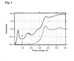
- Fig. 1 shows the Vis-NIR spectra of 6 x 10 -4 M solution of Z-907Na complex and the working solution Z-907Na/SWCNT. In the latter case, we detected the characteristic features of carbon nanotubes.
- Semiconducting SWCNT are characterized by optical transitions between van Hove singularities at ca. 0.7 eV and 1.3 eV for the first and second pair of singularities, respectively.
- Metallic tubes manifest themselves by a transition at 1.8 - 1.9 eV, which corresponds to the first pair of Van Hove singularities.
- the main peak of Z-907Na occurs at ca. 2.35 eV, and it is blue shifted by ca. 50 meV in the SWCNT-containing solution ( Fig. 1 ).
- the Z-907Na complex acts as an efficient surfactant for SWCNT, due to the presence of hydrophobic aliphatic C 9 chains (Scheme 1), which interact with the carbon tube surface.
- Scheme 1 hydrophobic aliphatic C 9 chains
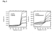
- Fig. 2 shows the cyclic voltammogram of a pure (carbon free) LiFePO 4 (bonded with 5% PVDF), which was treated by dip-coating into 6 x 10 4 mol/L solution of Z-907Na for 3 hours, rinsed with AN/t-BuOH and dried in vacuum at room temperature.
- the right chart plots analogous data for pure LiFePO 4 electrode, which was treated with Z-907Na/SWCNT solution in the same way. We see a plateau anodic current, which indicates the so-called "molecular wiring" of LiFePO 4 [18] .
- the Z-907Na complex (as in Scheme 1, can transport electronic charge via surface percolation in adsorbed monolayer even on insulating surfaces like Al 2 O 3 [9] .
- the NCS groups act as mediators for the surface-confined hole percolation, and the bipyridine ligands transport electrons.
- the hole diffusion coefficient within adsorbed Z-907Na was of the order of 10 -9 cm 2 /s above the charge percolation threshold, ca. 50% of surface coverage [19] .
- Li/Li + [19,21] which is just sufficient for the anodic wiring of LiFePO 4 (redox potential 3.45 V vs. Li/Li + ) but not for cathodic wiring [20] .
- Our data on Fig. 2 also confirm that the COOH/COONa are suitable anchoring groups for LiFePO 4 . similar to the phosphonic acid anchoring group employed previously [20] .
- the total anodic charge was between 2 to 4 mC (0.4 to 0.7 mAh/g) for the electrode in Fig. 2 (left chart) at the given scan rates. This charge was not much larger at slower scanning and moreover, the electrode was unstable during repeated cycling at slower scan rates.
- the molecular wiring via adsorbed Z-907Na is sensitive to imperfections in the surface layer, which hamper the hole percolation.
- Fig. 2 shows a variant of the previous experiment, where the LiFePO 4 film was treated by dip-coating into Z-907Na/SWCNT solution.
- the anodic current is now considerably smaller, which may be due to poor accessibility of the pores in the pre-deposited LiFePO 4 layer for SWCNT.
- the carbon tubes are typically 1-10 ⁇ m long, they cannot easily interpenetrate the compact porous solid.
- the Z-907Na/SWCNT assemblies reside prevailingly on top of the LiFePO 4 layer.
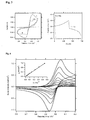
- Fig. 3 shows cyclic voltammogram of this electrode compared to the voltammograms of an electrode, which was fabricated in the same way, but instead of using Z-907Na complex as a surfactant, the SWCNT were solubilized by pyrene butanoic acid. Obviously, this electrode shows practically no activity, indicating that the sole carbon nanotubes do not promote the charging/discharging of LiFePO 4 .
- the electrode from carbon-coated LiFePO 4 shows much smaller activity compared to our Z-907Na/SWCNT electrode at the same conditions.
- a comparative experiment with Z-907Na/SWCNT treated LiMnPO 4 powder also showed practically no electrochemical activity (data not shown).
- the charging/discharging of LiFePO 4 via the surface attached Z-907Na/SWCNT assemblies was reasonably reversible, providing at 0.1 mV/s scan rate the specific capacity of ca. 41 mAh/h for anodic process and 40 mAh/g for cathodic process (see data on Fig. 3 ).
- the electrode was also quite stable, showing no obvious capacity fading in repeated voltammetric scans.
- Fig. 3 (right chart) demonstrates that the Z-907Na/SWCNT electrode delivered at the charge rate C/5 and cut-off potentials 4 and 2.7 V vs. Li/Li + the anodic charge of 390 mC (51 mAh/g) and the cathodic charge of 337 mC (44 mAh/g).
- a comparative test with carbon-coated LiFePO 4 (Nanomyte BE-20, NEI) cannot be carried out due to negligible activity of this electrode at the C/5 rate. Even at ten times slower charging, this carbon-coated electrode exhibits much worse performance (curve B in Fig 3 , right chart).
- the applied amount of working solution Z-907Na/SWCNT (1.5 mL; 6 x 10 -4 mol/L Z-907Na) gives the upper limit of the adsorbed Z-907Na to be 0.9 ⁇ mol and the amount of adsorbed carbon (in the form of SWCNT) to be 6.3 ⁇ mol per 200 mg of LiFePO 4 (See Experimental Section).
- the concentration of elemental carbon from SWCNT was, therefore, less than 0.04 wt% in the final solid material). From the BET surface area of LiFePO 4 we can calculate that the surface coverage of Z-907Na is equivalent to about one molecule per 2 nm 2 . This is not far from the monolayer coverage, if we take into account the usual dimensions of Ru-bipyridine molecules [22] .
- Reagent F.W (uma) g ml mol I 540.76 0.5 0.925 ⁇ 10 -3 HCl 37% 35.5 5
- Method In a 25 ml three necked round bottomed flask (equipped with a condenser) were placed 0.5 g of I dissolved in a 12N HCl water solution (5 ml). The solution was stirred at reflux temperature for about one night. The reactor was kept in the dark. The reaction was followed by 1H-NMR until the signal of CH 2 of the esters has disappeared. Then the excess of chlorhydric acid was distilled off at reduced pressure, and the product collected as brown viscous oil. The product was dissolved two to three times in toluene and the solvent distilled off at reduced pressure.
- Reagent F.W (uma) g ml mol I 483.56 1 2.07 ⁇ 10 -3 II 166.16 8 Method: In a 25 ml three necked round bottomed flask (equipped with a condenser) were placed 1 g of I dissolved in triethylphosphite (8 ml). The solution was stirred at 120°C for about three hour. The reactor was kept in the dark and in a inert atmosphere (argon). Then the excess of triethylphosphite was distilled off at reduced pressure and the product collected as brown liquid. The purification was carried out by flash chromatography on silica gel (petrol ether/ethyl acetate 5:1). The pure product is a colourless liquid (Yield: 85%).
- Fig. 4 shows the cyclic voltammogram of DW adsorbed on mesoscopic TiO 2 electrode.
- DW exhibits reversible charge-transfer reaction, despite the TiO 2 is insulating in this potential region and inactive for (dark) electrochemistry. This is an evidence for cross-surface electron/hole percolation in the DW molecules.
- UV-spectrophotometry indicated the surface coverage of TiO 2 with DW ref 23 to be 0.3 nmol/cm 2 , which translates into ⁇ 2 molecules/nm 2 . (The surface coverage is refereed to the overall physical surface of the electrode material, which was 55 cm 2 ).
- D + 9.10 -10 cm 2 /s. This coefficient describes actually the cross surface motion of holes though the DW monolayer, and not the mass transport, because the translational motion of adsorbed molecules is obviously excluded. Therefore, the charge transfer stops, if a percolation threshold is achieved.
- Fig. 5 shows cyclic voltammograms of DW on TiO 2 .
- the peak-to-peak splitting for the first scan was between 41 to 59 mV.
- the splitting is narrower than 60/ n . mV expected for a reversible redox system in solution, which indicates the surface confinement of DW.
- the integral voltammetric charge drops by ca. 2 % per cycle and also the peak-to-peak splitting increases. This illustrates that there are certain limits of the stability of the DW/TiO 2 system at these conditions.
- Fig.6 shows the cyclic voltammograms of DW adsorbed on LiMnPO 4 electrode.
- the behavior is similar to that on TiO 2 (cf. Fig. 4 ).
- LiMnPO 4 behaves like an inert (insulating) support, and molecular wiring towards oxidative delithiation of LiMnPO 4 is absent. This is understandable because the available redox potential of DW does not provide enough driving force for this reaction.
- the cross-surface charge transport is ca.
- LiMnPO 4 three times faster on LiMnPO 4 compared to TiO 2 . This might be due to different surface morphology: whereas TiO 2 is a mesoporous material with statistically sintered 20-nm particles, the LiMnPO 4 consists of platelets ca. 200 nm in size, exposing the (010) faces on which the DW molecules can be assembled in a more organized way.
- the surface coverage of LiFePO 4 with DW was analyzed spectrophotometrically and found to be 0.5 nmol/cm 2 (referred to the BET surface area of the electrode material), which is ca. 3 molecules/nm 2 .
- This surface coverage is similar to that found for TiO 2 ( vide ultra ) and also comparable to that reported for the BMABP/LiFePO 4 system: 2.5 molecules/nm 2 .
- the surface concentration of 2 - 3 molecules/nm 2 seems to be representative for monolayer coverage for these relatively small organic molecules with one phosphonic anchor.
- the gradual delithiation of LiFePO 4 during repeated cycling from faster to slower scan rates might, actually, caused this effect too.
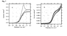
- Fig. 7A is the behaviour of a blank LiFePO 4 film, which was not treated by DW. This electrode shows negligible electrochemical activity, as it is expected for a stoichiometric olivine, free from any carbon additives.
- Fig. 7B presents the voltammogram of an electrode, which was delithiated by repeated cycling, followed by one-hour charging at a constant potential of 4.2 V.
- the total passed charge was equivalent to ca. 15 % of the theoretical charge capacity (170 mAh/g) of the used electrode.
- This electrode still exhibits the wiring effect, albeit the current for the 15 %-delithiated electrode is ca. 40 times smaller than for the fresh electrode.
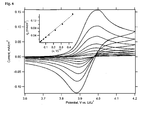
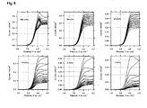
- Fig. 8 summarizes the data for six electrodes; each plot at the given scan rate starts from a virgin electrode, while care was taken that all six electrodes had roughly identical film mass and area ( ⁇ 3 mg/cm 2 ). The molecular couple is still seen at the scan rate of 100 mV/s (cf. Figs.7 and 8 ). At the scan rates of 50 and 20 mV/s, we can trace an almost ideal molecular wiring behaviour, which is also apparent at slower scanning of partly charged electrodes. Nevertheless, slower scanning of a virgin electrode confirms that the wiring current drops significantly already at the time scale of cyclic voltammetry.
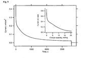
- Fig. 9 shows potential-step chronoamperometry test of a virgin DW-wired LiFePO 4 electrode.
- the current is not linear with t -1/2 , in other words the Cotrell-like behaviour is not traceable like for redox wiring of molecules on insulating supports (TiO 2 ).
- the chronoamperometry is not controlled by diffusion, but by effects associated with the interfacial molecular wiring. Consequently, chronoamperometry helps to evaluate the wiring effect itself.
- During one-hour of constant charging at 4.2 V we can pass a charge equivalent to ca. 12 % of the total faradic capacity of the electrode material (170 mAh/g). This is more explicitly shown in Fig 9 -inset, where the current is expressed in a way conventional in battery testing. Obviously, charging rates of ca. C/2 - C/10 are applicable for fresh electrodes and shallow charging.
Abstract
Description
- The lithium insertion materials in commercial electrochemical cells comprise 2-25 wt. %, typically 10 wt. % conductive additives. These conductive agents do not participate in the redox reactions and therefore represent inert mass reducing the energy storage capacity of the electrode. This situation is especially severe as the lithium insertion material or its deintercalated state has very poor electronic conductivity as for olivine cathode materials.
- The advent of olivine phosphates as novel cathode materials for Li-ion batteries stems from the pioneering work of Goodenough et al. [1], who had first reported on two generic structures, viz. LiFePO4 and LiMnPO4 as well as the mixed phases, LiFexMn1-xPO4 (0 < x < 1). Both materials are very poor electronic conductors; the reported conductivities of LiFeP04 and LiMnPO4 are (~10-8 to 10-9) S/cm and (<10-10 to 3·10-9) S/cm, respectively [2-4]. Ceder et al. [5] have measured the optical band gap of LiFePO4 to be 3.8-4.0 eV, which would account for negligible concentration of intrinsic charge carriers. Therefore the electronic charge cannot be transported by delocalized electrons in the olivine conduction band, but via localized polarons at the transition metal, whose mobility is a thermally activated (hoping) process. Recently, Nazar et at. [6] have pointed out that the polaron hopping is strongly correlated with the Li+ transport. Enhancement of the electronic conductivity of LiMPO4 (M = Mn, Fe) requires proper engineering of the material morphology [2,7-10] and surface modification, while the carbon coating is the obvious strategy [4,8,10-13]. An alternative pathway is based on the doping of LiFePO4 by supervalent cations, such as Zr4+ and Nb5+ at the Li+ site [14]. Eventually, the conductive coating on LiFePO4 olivine might not be a pure elemental carbon, but phosphides or phosphocarbides as demonstrated by Nazar et al. [3] by the EDX elemental map of grain boundaries. In this particular case, the phosphides Fe2P and Fe75P15C10 were assumed, but the presence of elemental carbon can also be convincingly demonstrated by Raman spectroscopy [8]
- In the conventional solid state synthesis of LiMPO4 (M = Mn, Fe), carbon is added to the precursor mixture composed of a stoichiometric amounts of the corresponding Li-, M- and PO4 3- salts [4,11]. During the synthesis, carbon simultaneously acts as a reductant, avoiding the formation of M3+ and also as a separator, blocking the growth of crystals [11]. The suppression of crystal growth by carbon manifests itself by the formation of particles in the range 60-100 nm. Li et al. [11] reported that LiMnPO4, which was synthesized in this way, delivered 140 mAh/g at 0.28 mA/cm2. Unfortunately this promising result was not reproduced by others [4,13], and the cited paper [11] remains controversial.
- LiMPO4 (M = Mn, Fe) can also be prepared at low-temperatures by direct precipitation from aqueous solutions [2,10,13]. In this case, the carbon coating can be made via subsequent ball-milling with acetylene black [10,13]. This strategy provided particle sizes between 100-200 nm and BET areas 23-13 m2/g [13], Obviously, the particle sizes of low-temperature ("chimie-douce") olivine [2,10,13] are, actually, similar to those of olivine from the solid state reaction with carbon additive [4]. Presumably, the smallest particles of LiMnPO4 (ca. 50 nm) were prepared in thin films by electrostatic spray deposition [9]. However, their discharge capacities were found to be only ca. 20 mAh/g at slow cyclic voltammetry [9]. We could speculate that this accounts for uncontrolled carbon coating (if any) in this particular case. The optimized carbon-coated LiMnPO4 materials with particle sizes around 130 nm exhibited 156 mAh/g at C/100 and 134 mAh/g at C/10 [10].
- Obviously, the slow polaron mobility in LiMPO4 is a fundamental problem, which can be, presumably minimized by decreasing the particle size and optimized decoration of particles with conductive carbon.
- In the
W02006131873 is described novel strategy for charging/discharging of virtually insulating cathode materials like LiMPO4 called molecular wiring. It is based on an efficient cross surface electron/hole transport in self-assembled redox active molecules adsorbed on the LiMPO4 surface. InEP-A-20060407 - This invention concerns electrochemically addressable lithium insertion electrode systems for electrochemical cells using non-aqueous organic electrolytes, quasi-solid gel electrolytes, solid electrolytes, or the like and in particular the use of said electrolytes in combination with porous electrode materials, i.e. doped or non-doped nanoparticles or sub-microparticles of lithium insertion materials and redox active compounds.
- This invention also concerns the configuration of the electrochemical cell containing the redox active compounds attached to SWCNT.
- Here we show a novel concept called nanotube wiring, which is based on anchoring of the redox relay - charge transport by redox active molecules - attached to SWCNT, which can improve the conductivity of the cathode material in Li-ion battery. The amphiphilic redox active compound contains hydrophobic and hydrophilic parts in the molecule; hence it can act as surfactants dispersing SWCNT. The hydrophobic part (e.g. aliphatic chain) serves for anchoring of SWCNT via non-covalent bonds. The hydrophilic part is represented by either ionic or uncharged polar functional groups (e.g. -COOH), which interact with the surface of the electrode active material. Because the adsorbed assembly does not occupy any significant extra volume of the whole electrode system, the electrode composite provides excellent energy density of the electrochemical cell. This concept is attractive due to larger currents, which can be drawn similar as in the redox targeting process, described in
EP-A-20060407 - It has been discovered that some amphiphilic redox active molecules interact to SWCNT can further anchor with the surface of electrode active material such as LiFeP04 (olivine). The assembly of redox molecule and SWCNT thus covers the surface of the active material, forming an electrochemically addressable electrode system. For cathodic lithium insertion material upon positive polarization the donor redox active compound (D) will be oxidized at current corrector and charges (holes) will be transported from the current collector to the lithium insertion material by the oxidized form of the redox active compound (D+). As the redox potential of the redox active compound is higher or matches closely the Fermi level of the lithium insertion material, D+ will be reduced by the lithium insertion material. Electrons and lithium ions will be withdrawn from it during battery charging. By contrast, during the discharging process, the oxidized species are reduced at current collector and charges (electrons) are transported from the current collector to the lithium insertion material by the redox active compound (D). Lithium ions and electrons are injected into the solid, as the redox potential of the redox active compound is lower or matches closely the Fermi level of the lithium insertion material.
- The cell is composed of two compartments, where the cathodic compartment comprises a cathodic lithium insertion material and redox active compound(s); the anodic compartment comprises an anodic lithium insertion material and redox active compound(s). These two compartments are separated by a separator. Compared to the whole electrode system, the redox active adsorbate does not occupy any significant extra volume of the whole electrode system. Hence with respect to prior art, the present invention allows reducing greatly the volume of the conductive additives resulting in a much improved energy storage density. The redox adsorbate is not soluble in the working electrolyte so the use of a special separator as described in
EP-A-20060407 - According to the present invention, a redox active molecule is attached to the SWCNT backbone by non-covalent bonding. A redox active centre (D) may be an organic compound or a metal complex having suitable redox potential as that of the battery material. In preferred configuration the redox active metal complex or organic compound (D) is localized between the SWCNT surface and the surface of electrode active material.

- Wherein [M] represents schematically the electrode material
- As used herein, the term "lithium insertion material" refers to the material which can host and release lithium ions reversibly. If the materials lose electrons upon charging, they are referred to as "cathodic lithium insertion material". If the materials acquire electrons upon charging, they are referred to as "anodic lithium insertion material".
- As used herein, the term "donor-type redox active compound" refers to those compounds that are present in the cathodic compartment of the cell, and act as molecular relay transporting charges between current collector and cathodic lithium insertion material upon charging/discharging. On the other hand, the term "acceptor-type redox active compound" refers to the molecules that present in the anodic compartment of the cell, and act as molecular relay transporting charges between current collector and anodic lithium insertion material upon charging/discharging.
- A redox active centre may be an organic compound or a metal complex having suitable redox potential as that of the lithium insertion material.
- In a preferred configuration the redox active centre is of the type given below,
 represents schematically the π system of the aforesaid substituent, Ral represents an aliphatic substituent with a saturated chain portion bound to the π system, and wherein q represents an integer, indicating that
 may bear more than one substituent Ral.
 - The π systemmay be an unsaturated chain of conjugated double or triple bonds of the type


wherein Rar is a H or monocyclic or oligocyclic aryl from C6 to C22,
wherein - Ral is -R1 or -O-R1 or -N(R1)2 or -NHR1 or


- According to a preferred embodiment, D is selected from benzol, naphtaline, indene, substituted triarylamine, fluorene, phenantrene, anthracene, triphenylene, pyrene, pentalene, perylene, indene, azulene, heptalene, biphenylene, indacene, phenalene, acenaphtene, fluoranthene, and heterocyclic compounds pyridine, pyrimidine, pyridazine, quinolizidine, quinoline, isoquinoline, quinoxaline, phtalazine, naphthyridine, quinazoline, cinnoline, pteridine, indolizine, indole, isoindole, carbazole, carboline, acridine, phenanthridine, 1,10-phenanthroline, thiophene, thianthrene, oxanthrene, and derivatives thereof, optionally be substituted.
- According to a preferred embodiment, D is selected from structures of formula (1-11) given below:

- Preferred p-type redox active compounds have the following structure:
-

X= PO3H2 or CO2H or SO3H or CONHOH or PO4H2
A= F or Cl or Br I or NO2 or COOR or Alkyl (C1 to C20) or CF3 or COR or OCH3 or H
B= F or Cl or Br I or NO2 or COOR or Alkyl (C1 to C20) or CF3 or COR or OCH3
A= B or A≠B
R= H or C1 to C20
X= PO3H2 or CO2H or SO3H or CONHOH or PO4H2 -


X= PO3H2 or CO2H or SO3H or CONHOH or PO4H2
Y= N or O or S
R1, R2, R3, R4 can be
F or Cl or Br I or NO2 or COOR or Alkyl (C1 to C20) or CF; or COR or OCH3 or H -

-

-
R is H or (CH2)p-En-(CH2)m-Acc (p= 0 to 24, linear or branched or with cycles; n= 0 to 24, m=0 to 24, linear or branched or with cycles; E is -CH=CH-, or -C≡C-, or -OCH2CH2-, and Acc is PO3H2 or CO2H or SO3H or CONHOH or PO4H2 or SO4H2 - Alternatively a redox active centre may be a metal complex having suitable redox potential as that of the lithium insertion material.
- In metal complexes as redox active centers, the preferred ligands coordinated to the metal, according to the invention are metal complexes having a formula selected from


n= 0 to 20
X= PO3H2 or CO2H or SO3H or CONHOH or PO4H2 or SO4H2
P= F or Cl or Br or I or NO2 or CN or NCSe or NCS or NCO


R, R1, R2 is same or different from COOR3 or PO3R3 or SO3R3 or CONR3OR3 or S04R3 or COR3 or CF3 or COCF3 or OR3 or NO2 or F or Cl or Br or I or NR3 or a linear or branched alkyl (C1 to C20) or H (where R3 is an alkyl (C1 to C20) or H) or comprises an additional n system located in conjugated relationship with the primary n system, the said substituent is of the type represents schematically the π system of the aforesaid substituent, Ral represents an aliphatic substituent with a saturated chain portion bound to the π system, and wherein q represents an integer, indicating that
 may bear more than one substituent Ral.
wherein at least one of substituents -R, -R1, -R2 is of formula (I), (2) or (3)


wherein Rar is a H or monocyclic or oligocyclic aryl from C6 to C22,
wherein - Ral is a H or -R1 or -O-R1 or -N(R1)2 or -NHR1 or


wherein the other one(s) of substituent(s) -R, -R1, -R2 is (are) the same or a different substituent of formula (1), (2) or (3), or is (are) selected from -H, -OH,
-R3, -OR3, COOH, COCF3, CN, Br, Cl, F, I, CF3, or -N(R3)2, wherein R3 is a linear or branched alkyl of 1 to 20 carbon atoms.
X= F or Cl or Br or I or NO2 or CN or NCSe or NCS or NCO


R, R1, R2 is same or different from COOR3 or PO3R3 or SO3R3 or CONR3OR3 or SO4R3 or COR3 or CF3 or COCF3 or OR3 or NO2 or F or Cl or Br or I or NR3 or a linear or branched alkyl (C1 to C20) or H (where R3 is an alkyl (C1 to C20) or H) or comprises an additional n system located in conjugated relationship with the primary π system, the said substituent is of the type represents schematically the π system of the aforesaid substituent, Ral represents an aliphatic substituent with a saturated chain portion bound to the n system, and wherein q represents an integer, indicating thatmay bear more than one substituent Ral.
wherein at least one of substituents -R, -R1, -R2 is of formula (1), (2) or (3)


wherein Rar is a H or monocyclic or oligocyclic aryl from C6 to C22,
wherein - Ral is a H or -R1 or -O-R or -N(R1)2 or -NHR or


wherein the other one(s) of substituent(s) -R, -R1, -R2 is (are) the same or a different substituent of formula (1), (2) or (3), or is (are) selected from -H, -OH, -R3, -OR3, COOH, COCF3, CN, Br, Cl, F, I, CF3, or -N(R3)2, wherein R3 is a linear or branched alkyl of 1 to 20 carbon atoms.
- R, R1, R2 may be same or different from COOR3 or PO3R3 or SO3R3 or CONR3OR3 or S04R3 or COR3 or CF3 or COCF3 or OR3 or NO2 or F or Cl or Br or I or NR3 or alkyl (C1 to C20) or H where R3 is an alkyl (C1 to C20) or H R, R1, R2 is same or different from COOR3 or PO3R3 or SO3R3 or CONR3OR3 or SO4R3 or COR3 or CF3 or COCF3 or OR3 or NO2 or F or Cl or Br or I or NR3 or a linear or branched alkyl (C1 to C20) or H (where R3 is a linear or branched alkyl (C1 to C20) or H) or comprises an additional n system located in conjugated relationship with the primary system, the said substituent is of the type
 represents schematically the π system of the aforesaid substituent, Ral represents an aliphatic substituent with a saturated chain portion bound to the n system, and wherein q represents an integer, indicating thatmay bear more than one substituent Ral.
wherein at least one of substituents -R, -R1, -R2 is of formula (1), (2) or (3)


wherein Rar is a H or monocyclic or oligocyclic aryl from C6 to C22,
wherein - Ral is a H or -R1 or -O-R1 or -N(R1)2 or -NHR1 or


wherein the other one(s) of substituent(s) -R, -R1, -R2 is (are) the same or a different substituent of formula (1), (2) or (3), or is (are) selected from -H, -OH,
-R3, -OR3, COOH, COCF3, CN, Br, Cl, F, I, CF3, or -N(R3)2, wherein R3 is a linear or branched alkyl of 1 to 20 carbon atoms.

B = alkyl (C to C20) or H
R, R1, R2 may be same or different from COOR3 or PO3R3 or SO3R3 or CONR3OR3 or S04R3 or COR3 or CF3 or COCF3 or OR3 or NO2 or F or Cl or Br or I or NR3 or alkyl (C1 to C20) or H where R3 is an alkyl (C1 to C20) or H R, R1, R2 is same or different from COOR3 or PO3R3 or SO3R3 or CONR3OR3 or SO4R3 or COR3 or CF3 or COCF3 or OR3 or NO2 or F or Cl or Br or I or NR3 or a linear or branched alkyl (C1 to C20) or H (where R3 is a linear or branched alkyl (C1 to C20) or H) or comprises an additional π system located in conjugated relationship with the primary π system, the said substituent is of the type represents schematically the π system of the aforesaid substituent, Ral represents an aliphatic substituent with a saturated chain portion bound to the π system, and wherein q represents an integer, indicating thatmay bear more than one substituent Ral.
wherein at least one of substituents -R, -R1, -R2 is of formula (1), (2) or (3)


wherein Rar is a H or monocyclic or oligocyclic aryl from C6 to C22,
wherein - Ral is a H or -R 1 or -O-R1 or -N(R1)2 or -NHR1 or


wherein the other one(s) of substituent(s) -R, -R1, -R2 is (are) the same or a different substituent of formula (1), (2) or (3), or is (are) selected from -H, -OH,
-R3, -OR3, COOH, COCF3, CN, Br, Cl, F, I, CF3, or -N(R3)2, wherein R3 is a linear or branched alkyl of 1 to 20 carbon atoms.


n= 0 to 20
X= PO3H2 or CO2H or SO3H or CONHOH or PO4H2 or SO4H2
P= F or Cl or Br or I or NO2 or CN or NCSe or NCS or NCO


R, R1, R2 may be same or different from COOR3 or PO3R3 or SO3R3 or CONR30R3 or SO4R3 or COR3 or CF3 or COCF3 or OR3 or NO2 or F or Cl or Br or I or NR3 or alkyl (C1 to C20) or H where R3 is an alkyl (C1 to C20) or H R, R1, R2 is same or different from COOR3 or PO3R3 or SO3R3 or CONR3OR3 or SO4R3 or COR3 or CF3 or COCF3 or OR3 or NO2 or F or Cl or Br or I or NR3 or a linear or branched alkyl (C1 to C20) or H (where R3 is a linear or branched alkyl (C1 to C20) or H) or comprises an additional π system located in conjugated relationship with the primary π system, the said substituent is of the type represents schematically the π system of the aforesaid substituent, Ral represents an aliphatic substituent with a saturated chain portion bound to the π system, and wherein q represents an integer, indicating thatmay bear more than one substituent Ral.
wherein at least one of substituents -R, -R1, -R2 is of formula (1), (2) or (3)


- wherein
- p is an integer from 0 to 20,
- therein
- Rar is a H or monocyclic or oligocyclic aryl from C6 to C22,
- wherein
- - Ral is a H or -R1 or -O-R1 or -N(R1)2 or -NHR1 or
- wherein R1,
- R'1 are same or different from -CH2P03H2, -CH2CO2H, -CH2SO3H, -CH2CONHOH, -CH2PO4H2, -CH2SO4H2, x ≥ 0,and 0 < n < 20.
- wherein the
- other one(s) of substituent(s) -R, -R1, -R2 is (are) the same or a different substituent of formula (I), (2) or (3), or is (are) selected from -H, -OH, -R3, -OR3, COOH, COCF3, CN, Br, Cl, F, I, CF3, or -N(R3)2, wherein R3 is a linear or branched alkyl of 1 to 20 carbon atoms.
- wherein
- p is an integer from 0 to 20,
- wherein
- Rar is a H or monocyclic or oligocyclic aryl from C6 to C22,
- wherein
- - Ral is a H -R1 or -O-R1 or -N(R1)2 or -NHR1 or
- wherein
- R1, R'1 are same or different from -CH2PO3H2, -CH2CO2H, -CH2SO3H, -CH2CONHOH, -CH2PO4H2, -CH2SO4H2, x ≥ 0,and 0 < n < 20.
- wherein
- the other one(s) of substituent(s) -R, -R1, -R2 is (are) the same or a different substituent of formula (1), (2) or (3), or is (are) selected from -H, -OH, -R3, -OR3, COOH, COCF3, CN, Br, Cl, F, I, CF3, or -N(R3)2, wherein R3 is a linear or branched alkyl of 1 to 20 carbon atoms.
- LiFePO4 was synthesized by a variant of solid state reaction [15] employing FeC2O4.2H2O and LiH2PO4 as precursors. Their stoichiometric amounts were mixed and ground in a planetary ball-milling machine for 4 h. Then the powder was calcined in a tube furnace with flowing Ar-H2 (92:8 v/v) at 600 °C for 24 h. After cooling down to room temperature, the sample was ground in agate mortar. The BET surface area of the powder was ca. 5 m2/g with an average particle size of 400 nm. X-ray diffraction confirmed the phase purity. The Ru-bipyridine complex, NaRu(4-carboxylic acid-4'-carboxylate(4,4'-dionyl-2,2'bipyridine)(NCS)2, coded as Z-907Na was synthesized as described elsewhere [16]. Single walled carbon nanotubes were grown by catalytic laser ablation method. The average diameter of tubes was determined by Raman and Vis-NIR spectroscopy to be ca. 1.3-1.4 nm. Other chemicals were from commercial sources and were used as received.
- SWCNT were dispersed with solutions of surfactants (either pyrene butanoic acid in dimethylformamide (DMF) or Z-907Na in acetonitrile+tert-butanol (1:1) (AN/t-BuOH) by sonication. The optimized synthetic protocol for Z-907Na was as follows: 9 mg of SWCNT was sonicated for 2 hours with 10 mL of 6·10-4 M Z-907Na in acetonitrile+ t-butanol (1:1). The resulting black-brown solution was centrifuged at 5000 rpm for 1 hour, while ca. 4 mg of undissolved carbon remained as a sediment. This working solution (abbreviated further as Z-907Na/SWCNT) was stable for at least weeks at room temperature without precipitation. Hence, the solution contained ca. 5 mg of dispersed SWCNT (417 µmol) and 6 µmol of Z-907Na (molar ratio C/Z-907Na ≈ 70). The olivine LiFePO4 (200 mg) was mixed with several portions (0.5 - 0.7 mL) of this working solution. At the initial stages, the supernatant turned to colorless within several seconds after mixing. After each addition of the Z-907Na/SWCNT solution, the slurry was centrifuged, supernatant separated and a next portion of the solution was added. This procedure was repeated until the supernatant did not decolorize. The total amount of applied solution was 1.5 mL. Finally the powder was washed with AN/t-BuOH and dried at room temperature. The same synthetic protocol was also adopted also for surface derivatization of LiFePO4 with pyrenebutanoic acid/SWCNT.
- Electrodes were prepared by mixing the powder of surface derivatized LiFePO4 with 5 wt% of polyvinylidene fluoride (PVDF) dissolved in N-methyl-2-pyrolidone. The resulting homogeneous slurry was then doctor-bladed onto F-doped conducting glass (FTO) and dried at 100°C overnight. Alternatively the slurry was coated on alumina current collector and dried at 100°C overnight. The typical film mass was 1.5 - 2 mg/cm2. Blank electrodes from pure LiFePO4 were prepared in the same way for reference experiments. A second reference material was a carbon-coated LiFePO4 (Nanomyte BE-20 from NEI Corporation, USA).
- The electrode was assembled in the electrochemical cell with Li reference and counter electrodes or alternatively in the Swagelok cell with Li negative electrode.
- Vis-NIR spectra were measured at
Varian Cary 5 spectrometer in 2 mm glass optical cells. The measurement was carried out in transmission mode with integrating sphere. Electrochemical experiments employed an Autolab PGSTAT 30 potentiostat. The electrolyte was 1 M LiPF6 in ethylene carbonate (EC)/dimethyl carbonate (DMC) (1:1, v:v). The reference and counter electrodes were from Li-metal. -
Fig. 1 shows the Vis-NIR spectra of 6 x 10⁻⁴ M solution of Z-907Na complex and the working solution Z-907Na/SWCNT. In the latter case, we detected the characteristic features of carbon nanotubes. Semiconducting SWCNT are characterized by optical transitions between van Hove singularities at ca. 0.7 eV and 1.3 eV for the first and second pair of singularities, respectively. Metallic tubes manifest themselves by a transition at 1.8 - 1.9 eV, which corresponds to the first pair of Van Hove singularities. The main peak of Z-907Na occurs at ca. 2.35 eV, and it is blue shifted by ca. 50 meV in the SWCNT-containing solution (Fig. 1 ). Obviously, the Z-907Na complex acts as an efficient surfactant for SWCNT, due to the presence of hydrophobic aliphatic C9 chains (Scheme 1), which interact with the carbon tube surface. There are many other molecules reported for solubilization of SWCNT, the most popular being sodium dodecyl sulfate [17], but, to the best of our knowledge, the solubilization of SWCNT by Ru-bipyridine complexes is here demonstrated for the first time.
-
Fig. 2 (left chart) shows the cyclic voltammogram of a pure (carbon free) LiFePO4 (bonded with 5% PVDF), which was treated by dip-coating into 6 x 10⁴ mol/L solution of Z-907Na for 3 hours, rinsed with AN/t-BuOH and dried in vacuum at room temperature. The right chart plots analogous data for pure LiFePO4 electrode, which was treated with Z-907Na/SWCNT solution in the same way. We see a plateau anodic current, which indicates the so-called "molecular wiring" of LiFePO4 [18]. The Z-907Na complex (as in Scheme 1, can transport electronic charge via surface percolation in adsorbed monolayer even on insulating surfaces like Al2O3 [9]. Here, the NCS groups act as mediators for the surface-confined hole percolation, and the bipyridine ligands transport electrons. The hole diffusion coefficient within adsorbed Z-907Na was of the order of 10-9 cm2/s above the charge percolation threshold, ca. 50% of surface coverage [19]. - The effect of molecular wiring was recently applied to the LiFePO4 electrode material, which can be wired by 4-(bis(4-methoxyphenyl)amino)benzylphosphonic acid [20]. In this case, the cross-surface hole percolation was followed by interfacial charging and discharging of LiFePO4 with Li+ ions [20]. Our data confirm that the hole-transport wiring is possible also with the Z-907Na complex, while a similar anodic current (exceeding 0.2 mA/cm2) can be wired to the LiFePO4 electrode at 0.1 V/s. The formal redox potential of Z-907Na adsorbed on inert TiO2 surface was about 3.5 V vs. Li/Li+ [19,21], which is just sufficient for the anodic wiring of LiFePO4 (redox potential 3.45 V vs. Li/Li+) but not for cathodic wiring [20]. Our data on
Fig. 2 also confirm that the COOH/COONa are suitable anchoring groups for LiFePO4. similar to the phosphonic acid anchoring group employed previously [20]. The total anodic charge was between 2 to 4 mC (0.4 to 0.7 mAh/g) for the electrode inFig. 2 (left chart) at the given scan rates. This charge was not much larger at slower scanning and moreover, the electrode was unstable during repeated cycling at slower scan rates. The molecular wiring via adsorbed Z-907Na is sensitive to imperfections in the surface layer, which hamper the hole percolation. -
Fig. 2 (right chart) shows a variant of the previous experiment, where the LiFePO4 film was treated by dip-coating into Z-907Na/SWCNT solution. Surprisingly, the anodic current is now considerably smaller, which may be due to poor accessibility of the pores in the pre-deposited LiFePO4 layer for SWCNT. As the carbon tubes are typically 1-10 µm long, they cannot easily interpenetrate the compact porous solid. Hence, the Z-907Na/SWCNT assemblies reside prevailingly on top of the LiFePO4 layer. We may assume that either some free complex (Z-907Na) may still be present in our working solution Z-907Na/SWCNT or may be partly released from the SWCNT upon interaction with the LiFePO4 surface. This causes poor surface coverage and attenuated molecular wiring in this case. - However, this situation changes dramatically, if the surface derivatization is carried out with the starting LiFePO4 powder instead of the doctor-bladed porous film.
Fig. 3 (left chart) shows cyclic voltammogram of this electrode compared to the voltammograms of an electrode, which was fabricated in the same way, but instead of using Z-907Na complex as a surfactant, the SWCNT were solubilized by pyrene butanoic acid. Obviously, this electrode shows practically no activity, indicating that the sole carbon nanotubes do not promote the charging/discharging of LiFePO4. Also the electrode from carbon-coated LiFePO4 (Nanomyte BE-20, NEI) shows much smaller activity compared to our Z-907Na/SWCNT electrode at the same conditions. A comparative experiment with Z-907Na/SWCNT treated LiMnPO4 powder also showed practically no electrochemical activity (data not shown). The charging/discharging of LiFePO4 via the surface attached Z-907Na/SWCNT assemblies was reasonably reversible, providing at 0.1 mV/s scan rate the specific capacity of ca. 41 mAh/h for anodic process and 40 mAh/g for cathodic process (see data onFig. 3 ). The electrode was also quite stable, showing no obvious capacity fading in repeated voltammetric scans. - The exceptional properties of our Z-907Na/SWCNT electrode are further demonstrated by galvanostatic charging/discharging cycle.
Fig. 3 (right chart) demonstrates that the Z-907Na/SWCNT electrode delivered at the charge rate C/5 and cut-off potentials 4 and 2.7 V vs. Li/Li+ the anodic charge of 390 mC (51 mAh/g) and the cathodic charge of 337 mC (44 mAh/g). A comparative test with carbon-coated LiFePO4 (Nanomyte BE-20, NEI) cannot be carried out due to negligible activity of this electrode at the C/5 rate. Even at ten times slower charging, this carbon-coated electrode exhibits much worse performance (curve B inFig 3 , right chart). - The applied amount of working solution Z-907Na/SWCNT (1.5 mL; 6 x 10⁻⁴ mol/L Z-907Na) gives the upper limit of the adsorbed Z-907Na to be 0.9 µmol and the amount of adsorbed carbon (in the form of SWCNT) to be 6.3 µmol per 200 mg of LiFePO4 (See Experimental Section). The concentration of elemental carbon from SWCNT was, therefore, less than 0.04 wt% in the final solid material). From the BET surface area of LiFePO4 we can calculate that the surface coverage of Z-907Na is equivalent to about one molecule per 2 nm2. This is not far from the monolayer coverage, if we take into account the usual dimensions of Ru-bipyridine molecules [22].
- The unprecedented activity of the electrode composite of LiFePO4 /Z-907Na/SWCNT is obviously due to the presence of carbon nanotubes, which can quickly transport the charge mediated by Z-907Na complex towards the olivine surface. This beneficial role of carbon nanotubes even promotes the cathodic process. This is almost absent in sole molecular wiring, due to low driving force of the redox process in Z-907Na for the reduction of Li1-xFePO4 back to the starting stoichiometric composition (
Fig. 2 ). -

-
Reagent F.W (uma) g ml mol I 540.76 0.5 0.925·10-3 HCl37% 35.5 5
1H-NMR (CDCl3): 1.18-1.35 ppm (bm, 36H, H chain + C(CH 3)3); 1.48 ppm (m, 2H, H chain); 1.81 ppm (m, 4H, H chain); 3.80 ppm (s, 3H, OCH 3); 3.94 ppm (t, 2H, OCH 2CH2); 6.81 ppm (d, 2H, Har). -

-


-
Reagent F.W (uma) g mol I 236.35 1 4.23·10-3 II 328 3.5 1.06·10-2 NaH 24 0.11 4.6 10-3 - Method: In a 100 ml three necked round bottomed flask (equipped with a Schlenk cock) were placed 0.11 g of NaH in anhydrous THF (15 ml) and 1 gram (4.23 mmol) of I. A gas evolution occurred for a few minutes, when it was finished 3.5 g (10 mmol) of 1,12-dibromododecane (dissolved in 15 ml of THF) were added. The mixture was stirred at room temperature for about one hour, then the system was refluxed for 20 hours. The reactor was kept in the dark and in a inert atmosphere (argon). Then the mixture was cooled to room temperature and 60 ml of water were added. The organic phase was extracted with DCM (3 x 60 ml), dried with CaCl2 and the solvent removed under vacuum to give a slightly yellow viscous liquid. The product was purified by flash chromatography on silica gel (ethyl acetate/petroleum ether 5:95), giving 1.7 g of pure (GC/MS) product (colourless liquid). Yield: 83%.
MS (EI): 482 (M+), 484 (M+2), 236; 221 (100%). 1H-NMR(CDCl3, t.a.): 1.28-1.32 ppm (bm, 36H, H chain + C(CH 3)3); 1.81 ppm (bm, 4H, H chain); 3.76 ppm (s, 3H, OCH 3); 3.90 ppm (t, 2H, OCH 2CH2); 4.10 ppm (t, 2H, CH 2Br); 6.81 ppm (bs, 2H, Har). -


-
Reagent F.W (uma) g ml mol I 483.56 1 2.07·10-3 II 166.16 8 - MS (EI): 540 (M+); 305 (100%). 1H-NMR (CDCl3): 1.18-1.35 ppm (bm, 42H, H chain + POCH2 CH 3 + C(CH 3)3); 1.71 ppm (m, 2H, H chain); 1.81 ppm (m, 4H, H chain); 3.80 ppm (s, 3H, OCH 3); 3.94 ppm (t, 2H, OCH 2CH2); 4.09 ppm (m, 4H,POCH 2CH3); 6.81 ppm (d, 2H, Har).
-
Fig. 4 shows the cyclic voltammogram of DW adsorbed on mesoscopic TiO2 electrode. DW exhibits reversible charge-transfer reaction, despite the TiO2 is insulating in this potential region and inactive for (dark) electrochemistry. This is an evidence for cross-surface electron/hole percolation in the DW molecules. UV-spectrophotometry indicated the surface coverage of TiO2 with DW ref 23 to be 0.3 nmol/cm2, which translates into ≈2 molecules/nm2. (The surface coverage is refereed to the overall physical surface of the electrode material, which was 55 cm2). The integrated voltammetric charge at the slowest scan (1 mV/s) was 1.51 mC, which translates into 0.28 nmol/cm2. Hence, the DW makes roughly a monolayer on the TiO2 surface, and is fully active for ambipolar charge transport from the FTO support. Inset inFig. 4 shows that the forward peak current density, Jp scales with the square root of the scan rate, ν1/2 according to the Randles-Sevcik equation:
(n is number of electrons). The concentration of DW in the film (thickness 2.5 µm) equals c 0 = 3.3.10-4 mol/cm3. From the slope of the line inFig. 4 (inset) and Eq. (1) we can calculate the diffusion coefficient D + = 9.10-10 cm2/s. This coefficient describes actually the cross surface motion of holes though the DW monolayer, and not the mass transport, because the translational motion of adsorbed molecules is obviously excluded. Therefore, the charge transfer stops, if a percolation threshold is achieved. The found D + is not too far from the value for Ru-bipyridine complex Z-907 adsorbed on TiO2 [D + = (1.5 to 4.1).10-9 cm2/s], but is by three orders of magnitude smaller than the value of "real" diffusion coefficient of DBB dissolved in electrolyte solution (1.6.10-6 cm2/s). -
Fig. 5 shows cyclic voltammograms of DW on TiO2. The peak-to-peak splitting for the first scan was between 41 to 59 mV. The splitting is narrower than 60/n. mV expected for a reversible redox system in solution, which indicates the surface confinement of DW. During repeated scanning, the integral voltammetric charge drops by ca. 2 % per cycle and also the peak-to-peak splitting increases. This illustrates that there are certain limits of the stability of the DW/TiO2 system at these conditions. -
Fig.6 shows the cyclic voltammograms of DW adsorbed on LiMnPO4 electrode. The behavior is similar to that on TiO2 (cf.Fig. 4 ). In other words, LiMnPO4 behaves like an inert (insulating) support, and molecular wiring towards oxidative delithiation of LiMnPO4 is absent. This is understandable because the available redox potential of DW does not provide enough driving force for this reaction. By using the same evaluation routine as for TiO2 we can calculate the diffusion coefficient from the slope of Jp vs. ν1/2 (inset inFig. 3 ) to be: D + = 3.10-9 cm2/s Ref23. Interestingly, the cross-surface charge transport is ca. three times faster on LiMnPO4 compared to TiO2. This might be due to different surface morphology: whereas TiO2 is a mesoporous material with statistically sintered 20-nm particles, the LiMnPO4 consists of platelets ca. 200 nm in size, exposing the (010) faces on which the DW molecules can be assembled in a more organized way. - Although LiMnPO4 is intact for molecular wiring (cf.
Fig. 6 ), this effect is well expressed for LiFePO4 olivine.Figure 7A shows that a constant current flows at potentials above ca. 4.1 V. This plateau ("wiring current") is indicative for subsequent chemical reaction of the oxidized molecule (DW+) with LiFePO4 olivine causing its oxidative delithiation:
- Interestingly, at faster scanning (200 mV/s) we may trace also the parent peaks of the DW redox couple, indicating that a fast molecular charge transfer reaction foreruns the interfacial hole injection into LiFePO4. This kind of behaviour was not yet reported for molecular wiring or targeting of LiFePO4. At slower scanning (20 mV/s, the molecular couple is not seen, and the voltammogram is dominated by the wiring current only. Both curves in
Fig 7A were acquired on fresh (non-treated) electrodes with roughly identical film's mass and surface area. - The surface coverage of LiFePO4 with DW was analyzed spectrophotometrically and found to be 0.5 nmol/cm2 (referred to the BET surface area of the electrode material), which is ca. 3 molecules/nm2. This surface coverage is similar to that found for TiO2 (vide ultra) and also comparable to that reported for the BMABP/LiFePO4 system: 2.5 molecules/nm2. Hence, the surface concentration of 2 - 3 molecules/nm2 seems to be representative for monolayer coverage for these relatively small organic molecules with one phosphonic anchor. Presumably, the gradual delithiation of LiFePO4 during repeated cycling from faster to slower scan rates might, actually, caused this effect too. Also shown on
Fig. 7A is the behaviour of a blank LiFePO4 film, which was not treated by DW. This electrode shows negligible electrochemical activity, as it is expected for a stoichiometric olivine, free from any carbon additives. - The voltammogram of partly delithiated electrode also shows more clearly that the wiring current is independent of the scan rate.
Fig. 7B presents the voltammogram of an electrode, which was delithiated by repeated cycling, followed by one-hour charging at a constant potential of 4.2 V. The total passed charge was equivalent to ca. 15 % of the theoretical charge capacity (170 mAh/g) of the used electrode. This electrode still exhibits the wiring effect, albeit the current for the 15 %-delithiated electrode is ca. 40 times smaller than for the fresh electrode. - To get more insight into the fading of wiring activity, we have tested the behaviour of a fresh DW/LiFePO4 electrode during ten subsequent CV scans at various scan rates.
Fig. 8 summarizes the data for six electrodes; each plot at the given scan rate starts from a virgin electrode, while care was taken that all six electrodes had roughly identical film mass and area (≈ 3 mg/cm2). The molecular couple is still seen at the scan rate of 100 mV/s (cf.Figs.7 and8 ). At the scan rates of 50 and 20 mV/s, we can trace an almost ideal molecular wiring behaviour, which is also apparent at slower scanning of partly charged electrodes. Nevertheless, slower scanning of a virgin electrode confirms that the wiring current drops significantly already at the time scale of cyclic voltammetry. -
Fig. 9 shows potential-step chronoamperometry test of a virgin DW-wired LiFePO4 electrode. The current is not linear with t -1/2, in other words the Cotrell-like behaviour is not traceable like for redox wiring of molecules on insulating supports (TiO2). This is quite understandable, because in our case, the chronoamperometry is not controlled by diffusion, but by effects associated with the interfacial molecular wiring. Consequently, chronoamperometry helps to evaluate the wiring effect itself. During one-hour of constant charging at 4.2 V, we can pass a charge equivalent to ca. 12 % of the total faradic capacity of the electrode material (170 mAh/g). This is more explicitly shown inFig 9 -inset, where the current is expressed in a way conventional in battery testing. Obviously, charging rates of ca. C/2 - C/10 are applicable for fresh electrodes and shallow charging. - Our data confirm that the wiring current is primarily controlled by the state of the DW/LiFePO4 interface, which is most easily described as the level of the LiFePO4 charging. This is further presented on
Fig. 10 , which compiles the data from cyclic voltammetry (plots like those inFigs. 4 and5 ) and chronoamperometry (Fig. 9 ). Voltammetric data (points) and chronoamperometry data (line) are reasonably matching. The wiring current seems to be roughly inversely proportional to the level of discharge, this is represented by a dashed line inFig. 9 . - The performance of a DW-wired LiFePO4 olivine is s far from that of the up-to-date carbon-coated LiFePO4 cathodes for Li-ion batteries. But it is certainly interesting, at least academically, that a monolayer of molecules can carry currents, needed for charging of conventional batteries. We may reasonably expect further performance upgrade, if the particle size of the electrode material gets smaller.
-
-
Fig. 1 . Vis-NIR spectrum of the working solution of single wall carbon nanotubes dispersed by Ru-complex, Z-907Na/SWCNT (curve A) and pure Ru-complex Z-907Na (curve B). The concentration of Ru-complex was 6 x 10⁻⁴ mol/L in both cases, the optical cell thickness was 2 mm. -
Fig. 2 . Pure LiFePO4 electrode (with 5 % PVDF; total film mass 1.54 mg/cm2) treated by dip coating into 6·10-4 mol/L solution of Z-907Na (left chart) or Z-907Na/SWCNT (right chart). - Scan rates (in mV/s): 50, 20, 10, 5 for curves from top to bottom. Electrolyte solution is 1 M LiPF6 in EC/DMC.
-
Fig. 3 . Left chart: Cyclic voltammograms (scan rates 0.1 mV/s); electrolyte solution 1 M LiPF6 in EC/DMC. Curve A: Electrode from LiFePO4 surface-derivatized with Z-907Na/SWCNT (2.04 mg/cm2). Curve B (dashed line): electrode from carbon-coated LiFePO4 (Nanomyte BE-20, 2.28 mg/cm2). Curve C: Electrode from LiFePO4 surface-derivatized with pyrene butanoic acid/SWCNT (1.83 mg/cm2). The current scale is multiplied by a factor of 10 for curve B.
Right chart: Galvanostatic charge/discharge cycle; electrolyte solution 1 M LiPF6 in EC/DMC. Curve A: Electrode from LiFePO4 surface-derivatized with Z-907Na/SWCNT (2.04 mg/cm2) charging rate C/5. Curve B (dashed line): electrode from carbon-coated LiFePO4 (Nanomyte BE-20, 2.28 mg/cm2) charging rate C/50. -
Fig. 4 : Cyclic voltammograms of DW adsorbed on mesoporous TiO2 film. Scan rates (in mV/s): 200, 100, 50, 20, 10, 5, 2, 1. Inset shows the forward peak current as a function of the square root of the scan rate. -
Fig. 5 : Cyclic voltammograms of DW adsorbed on mesoporous TiO2 film. Scan rate 1 mV/s. Ten successive scans were accumulated. -
Fig. 6 : Cyclic voltammograms of DW adsorbed on LiMnPO4 electrode. Scan rates (in mV/s): 200, 100, 50, 20, 10, 5, 2, 1. Inset shows the forward peak current as a function of the square root of the scan rate. -
Fig. 7 : Cyclic voltammograms of DW-wired LiFePO4 electrode. A: Fresh electrode: first scan at 200 mV/s (red), 20 mV/s (blue). For comparison, green line is for LiFePO4 electrode without DW (20 mV/s). B: Used electrode (after 15 % charge): scan rates (in mV/s): 20 (red), 10 (blue), 5 (green), 2 (black), 1 (magenta). -
Fig. 8 : Cyclic voltammograms of DW-wired LiFePO4 electrode. Ten successive scans were accumulated for each given scan rate. -
Fig. 9 : Potential-step chronoamperometry of DW-wired LiFePO4 electrode. The potential step was from 3.5 V to 4.2 V (3600 s) to 3.5 V (300 s). Inset shows the same data recalculated in C-rate charging vs. charge capacity of the actual electrode assuming 170 mAh/g as the theoretical charge capacity. -
Fig. 10 : Compilation of the measured wiring currents as a function of the level of charging assuming 170 mAh/g (theoretical charge capacity) as thereference 100 % charge. Points: data from CV at varying scan rates between 1 to 200 mV/s. Curve: data from potential-step chronoamperometry (3.5 - 4.2 V (3600 s) - 3.5 V). Also shown is a model hyperbola (dashed line) assuming the wiring current were inversely proportional to the relative charge. -
- [1] A. K. Padhi, K. S. Nanjundasawamy, J. B. Goodenough, J.Electrochem.Soc. 1997, 144, 1188-1194.
- [2] C. Delacourt, L. Laffont, R. Bouchet, C. Wurm, J. B. Leriche, M. Mocrette, J. M. Tarascon, C. Masquelier, J.Electrochem.Soc. 2005, 153, A913-A921.
- [3] P. S. Herle, B. Ellis, N. Coombs, L. F. Nazar, Nature Mat. 2004, 3, 147-152.
- [4] M. Yonemura, A. Yamada, Y. Takei, N. Sonoyama, R. Kanno, J.Electrochem.Soc. 2004, 151, A1352-A1356.
- [5] F. Zhou, K. Kang, T. Maxisch, G. Ceder, D. Morgan, Solid State Comm. 2004, 132, 181-186.
- [6] B. Ellis, L. K. Perry, D. H. Ryan, L. F. Nazar, J.Am.Chem.Soc. 2006,128.
- [7] R. Dominko, M. Bele, M. Gaberseck, M. Remskar, D. Hanzel, J. M. Goupil, S. Pejovnik, J. Jamnik, J.Power Sources 2006, 153, 274-280.
- [8] T. Nakamura, Y. Miwa, M. Tabuchi, Y. Yamada, J.Electrochem.Soc. 2006, 153, A1108-A1114.
- [9] J. Ma, Z. Qin, J.Power Sources 2005, 148, 66-71.
- [10] N. H. Kwon, T. Drezen, 1. Exnar, I. Teerlinck, M. Isono, M. Grätzel, Electrochem.Solid State Lett. 2006, 9, A277-A280.
- [11] A. Yamada, M. Hosoya, S. C. Chung, Y. Kudo, K. Hinokuma, K. Y. Liu, Y. Nishi, J.Power Sources 2003, 119-121, 232-238.
- [12] G. Li, H. Azuma, M. Tohda, Electrochem.Solid State Lett. 2002, 5, A135-A137.
- [13] C. Delacourt, P. Poizot, M. Morcrette, J. M. Tarascon, C. Masquelier, Chem.Mater. 2004, 16, 93-99.
- [14] S. Y. Chung, J. T. Bloking, Y. M. Chiang, Nature Mat. 2002, 1, 123-128.
- [15] D. Wang, H. Li, Z. Wang, X. Wu, Y. Sun, X. Huang, L. Chen, J. Solid State Chem. 2004, 177, 4582-4587.
- [16] P. Wang, B. Wenger, R. Humphry-Baker, J. Moser, J. Teuscher, W. Kantlehner, J. Mezger, E. V. Stoyanov, S. M. Zakeeruddin, M. Grätzel, J.Am.Chem.Soc, 2005,127, 6850-6856.
- [17] D. A. Britz, A. N. Khlobystov, Chem.Soc.Rev. 2006, 35, 637-659.
- [18] S. W. Boettcher, M. H. Bartl, J. G. Hu, G. D. Stucky, J.Am.Chem.Soc. 2005, 127, 9721-9730.
- [19] Q. Wang, S. M. Zakeeruddin, M. K. Nazeeruddin, R. Humphry-Baker, M. Grätzel, J.Am.Chem.Soc. 2006,128, 4446-4452.
- [20] Q. Wang, N. Evans, S. M. Zekeeruddin, I. Exnar, M. Grätzel, J. Am. Chem. Soc,. 2006.
- [21] P. Wang, S. M. Zakeeruddin, P. Comte, R. Charvet, R. Humphry-Baker, M. Grätzel, J.Phys.Chem.B 2003,107, 14336-14341.
- [22] M. K. Nazeeruddin, P. Pechy, T. Renouard, S. M. Zakeeruddin, R. Humphry-Baker, P. Comte, P. Liska, L. Cevey, E. Costa, V. Shklover, L. Spiccia, G. B. Deacon, C. A. Bignozzi, M. Grätzel, J.Am.Chem.Soc. 2001, 123, 1613-16 24.
- [23] L. Kavan, I. Exnar, J. Cech and M. Grätzel, Chem. Mater., (2007).
- [24] J. R. Dahn, J. Jiang, L. Moshurchak, M. D. Fleischauer, C. Buhrmester and L. J. Krause, J. Electrochem. Soc., 152, A1283 (2005).


n= 0 to 20
X= PO3H2 or CO2H or SO3H or CONHOH or PO4H2 or SO4H2
P= CN or NCSe or NCS or NCO


R, R1, R2 may be same or different from COOR3 or PO3R3 or SO3R3 or CONR3OR3 or S04R3 or COR3 or CF3 or COCF3 or OR3 or NO2 or F or Cl or Br or I or NR3 or alkyl (C1 to C20) or H where R3 is an alkyl (C1 to C20) or H R, Tri, R2 is same or different from COOR3 or PO3R3 or SO3R3 or CONR3OR3 or SO4R3 or COR3 or CF3 or COCF3 or OR3 or NO2 or F or Cl or Br or I or NR3 or a linear or branched alkyl (C1 to C20) or H (where R3 is a linear or branched alkyl (C1 to C20) or H) or comprises an additional π system located in conjugated relationship with the primary π system, the said substituent is of the type
wherein at least one of substituents -R, -R1, -R2 is of formula (1), (2) or (3)


wherein Rar is a H or monocyclic or oligocyclic aryl from C6 to C22,
wherein - Ral is H or -R1 or -O-R1 or -N(R1)2 or -NHR1 or


wherein the other one(s) of substituent(s) -R, -R1, -R2 is (are) the same or a different substituent of formula (1), (2) or (3), or is (are) selected from -H, -OH,
-R3, -OR3, COOH, COCF3, CN, Br, Cl, F, I, CF3, or -N(R3)2, wherein R3 is a linear or branched alkyl of 1 to 20 carbon atoms.


n= 0 to 20
X= PO3H2 or CO2H or SO3H or CONHOH or PO4H2 or SO4H2
P= CN or NCSe or NCS or NCO or pyrazine.


R, R1, R2 may be same or different from COOR3 or PO3R3 or SO3R3 or CONR30R3 or SO4R3 or COR3 or CF3 or COCF3 or OR3 or NO2 or F or Cl or Br or I or NR3 or alkyl (C1 to C20) or H where R3 is an alkyl (C1, to C20) or H R, R1, R2 is same or different from COOR3 or PO3R3 or SO3R3 or CONR3OR3 or SO4R3 or COR3 or CF3 or COCF3 or OR3 or NO2 or F or Cl or Br or I or NR3 or a linear or branched alkyl (C1 to C20) or H (where R3 is a linear or branched alkyl (C1 to C20) or H) or comprises an additional π system located in conjugated relationship with the primary π system, the said substituent is of the type
wherein at least one of substituents -R, -R1, -R2 is of formula (1), (2) or (3)


R, R1 R2 may be same or different from COOR3 or PO3R3 or SO3R3 or CONR3OR3 or SO4R3 or COR3 or CF3 or COCF3 or OR3 or NO2 or F or Cl or Br or I or NR3 or alkyl (C1 to C20) or H where R3 is an alkyl (C1 to C20) or H R, R1, R2 is same or different from COOR3 or P03R3 or SO3R3 or CONR3OR3 or SO4R3 or COR3 or CF3 or COCF3 or OR3 or NO2 or F or Cl or Br or I or NR3 or a linear or branched alkyl (C1 to C20) or H (where R3 is a linear or branched alkyl (C1 to C20) or H) or comprises an additional π system located in conjugated relationship with the primary π system, the said substituent is of the type
wherein at least one of substituents -R, -R1, -R2 is of formula (1), (2) or (3)


wherein Rar is a H or monocyclic or oligocyclic aryl from C6 to C22,
wherein - Ral is -R1 or -O-R1 or -N(R1)2 or -NHR1 or


wherein the other one(s) of substituent(s) -R, -R1, -R2 is (are) the same or a different substituent of formula (1), (2) or (3), or is (are) selected from -H, -OH, -R3, -OR3, COOH, COCF3, CN, Br, Cl, F, I, CF3, or -N(R3)2, wherein R3 is a linear or branched alkyl of 1 to 20 carbon atoms.
Claims (21)
- A rechargeable electrochemical cell with improved energy density, comprising cathodic or anodic lithium insertion materials with p- or n-type redox active compounds, said electrochemical cell comprising two compartments separated by a separating element, the first compartment containing cathodic lithium insertion material and SWCNT attached with p-type redox active compounds and/or the second compartment containing anodic lithium insertion material and SWCNT attached with n-type redox active compound said separating element being permeable for lithium ions.
- A rechargeable electrochemical cell according to claim 1, comprising:(a) A first electrode compartment comprising cathode lithium insertion material with SWCNT attached redox active compound, negative electrode and electrolyte. The first oxidation potential of the p-type redox active polymer compound matches the cathode lithium insertion material.(b) A second electrode compartment comprising anode lithium insertion material with SWCNT attached redox active compound, positive electrode and electrolyte. The first reduction potential of the n-type redox active compound matches the anodic lithium insertion material.(c) At least one of the electrode compartments is with redox active molecule attached SWCNT.
- The rechargeable electrochemical cell according to claim 2, wherein the nano- or sub-micrometer sized cathode lithium insertion material is selected from doped or non-doped oxides of the formula:-
LiV3O8 or LiMO2, where M is one or more elements selected from Co, Ni, Mn, Fe, W, V; or mixtures therof;
phosphor-olivines of the formula LiMPO4 wherein M is one or more elements selected from Fe, Co, Mn, Ni, VO, Cr and mixtures thereof and
spinels and mixed spinels of the formula LixMn2O4 or Li2CoxFeyMnzO8. - The rechargeable electrochemical cell according to claim 2, wherein the nano- or sub-micrometer sized anodic lithium insertion material is selected from carbon, TiO2, Li4Ti5O12, SnO2, SnO, and Si.
- The rechargeable electrochemical cell according to claim 2, wherein the particle size of the lithium insertion materials ranges from 10nm to 100m.
- According to the claim 2 the redox active molecule is attached to the SWCNT, either by covalent bonding or non-covalent bonding or electrostatic interaction.
- The rechargeable electrochemical cell according to claim 6, wherein the redox active compound is an organic compound selected from equation (II)
 represents schematically the π system of the aforesaid substituent, Ral represents an aliphatic substituent with a saturated chain portion bound to the π system, and wherein q represents an integer, indicating that
 may bear more than one substituent Ral.
wherein at least one of substituents -R, -R1, -R2 is of formula (1), (2) or (3)

 wherein p is an integer from 0 to 20,


The embodiment, D is selected from benzol, naphtaline, indene, substituted triarylamine, fluorene, phenantrene, anthracene, triphenylene, pyrene, pentalene, perylene, indene, azulene, heptalene, biphenylene, indacene, phenalene, acenaphtene, fluoranthene, and heterocyclic compounds pyridine, pyrimidine, pyridazine, quinolizidine, quinoline, isoquinoline, quinoxaline, phtalazine, naphthyridine, quinazoline, cinnoline, pteridine, indolizine, indole, isoindole, carbazole, carboline, acridine, phenanthridine, 1,10-phenanthroline, thiophene, thianthrene, oxanthrene, and derivatives thereof, optionally be substituted.
According to a preferred embodiment, D is selected from structures of formula (1-11) given below:

- According to claim 7, preferred embodiments for D may be selected from structures (12) and (13) given below:

- The rechargeable electrochemical cell according to claim 6, wherein the redox active compound is of the formula (III) as follows:

X= PO3H2 or CO2H or SO3H or CONHOH or PO4H2
A= F or Cl or Br I or NO2 or COOR or Alkyl (C1 to C20) or CF3 or COR or OCH3 or H
B= F or Cl or Br I or NO2 or COOR or Alkyl (C1 to C20) or CF3 or COR or OCH3
A=B or A≠B - The rechargeable electrochemical cell according to claim 6, wherein the redox active compound is of the formula (IV) as follows:

R= H or C1 to C20
X= PO3H2 or CO2H or SO3H or CONHOH or PO4H2 - The rechargeable electrochemical cell according to claim 6, wherein the redox active compound is of the formula (V) to (X) as follows:


X= PO3H2 or CO2H or SO3H or CONHOH or PO4H2
Y= N or O or S
R1, R2, R3, R4 can be F or Cl or Br I or NO2 or COOR or Alkyl (C1 to C20) or CF3 or COR or OCH3 or H - The rechargeable electrochemical cell according to claim 6, wherein the redox active compound is of the formula (XI) as follows:

R is H or (CH2)p-En-(CH2)m-Acc (p=0 to 24, linear or branched or with cycles; n=0 to 24, m= 0 to 24, linear or branched or with cycles; E is -CH=CH-, or -C≡C-, or -OCH2CH2-, and Acc is PO3H2 or CO2H or SO3H or CONHOH or PO4H2 or SO4H2. - The rechargeable electrochemical cell according to claim 6, wherein the redox active compound is of the formula (XII) as follows:

- The rechargeable electrochemical cell according to claim 6, wherein the redox active compound is of the formula (XIII) as follows:

R is H or (CH2)p-En-(CH2)m-Acc (p= 0 to 24, linear or branched or with cycles; n= 0 to 24, m=0 to 24, linear or branched or with cycles; D is -CH=CH-, or -C≡C-, or -OCH2CH2-, and Acc is PO3H2 or CO2H or SO3H or CONHOH or PO4H2 or SO4H2. - According to claims 12 to 14 the most preferred compound is 12-(2,5-di-tert-butyl-4methoxyphenoxy) dodecyl phosphonic acid.
- The rechargeable electrochemical cell according to claim 6, wherein the redox active compound is a metal complex of the formula (XIV) or (XV) as follows:


n= 0 to 20
X= PO3H2 or CO2H or SO3H or CONHOH or PO4H2 or SO4H2
P= F or Cl or Br or I or NO2 or CN or NCSe or NCS or NCO


R, R1, R2 is same or different from COOR3 or PO3R3 or SO3R3 or CONR3OR3 or SO4R3 or COR3 or CF3 or COCF3 or OR3 or NO2 or F or Cl or Br or I or NR3 or a linear or branched alkyl (C1 to C20) or H (where R3 is an alkyl (C1 to C20) or H) or comprises an additional π system located in conjugated relationship with the primary π system, the said substituent is of the type represents schematically the π system of the aforesaid substituent, Ral represents an aliphatic substituent with a saturated chain portion bound to the π system, and wherein q represents an integer, indicating thatmay bear more than one substituent Ral.
wherein at least one of substituents -R, -R1, -R2 is of formula (1), (2) or (3)


wherein Rar is a H or monocyclic or oligocyclic aryl from C6 to C22,
wherein - Ral is -R1 or -O-R1 or -N(R1)2 or -NHR1 or


wherein the other one(s) of substituent(s) -R, -R1, -R2 is (are) the same or a different substituent of formula (1), (2) or (3), or is (are) selected from -H, -OH, -R3, -OR3, COOH, COCF3, CN, Br, Cl, F, I, CF3, or -N(R3)2, wherein R3 is a linear or branched alkyl of 1 to 20 carbon atoms. - The rechargeable electrochemical cell according to claim 6, wherein the redox active compound is a metal complex of the formula (XVI) as follows:

X= F or Cl or Br or I or NO2 or CN or NCSe or NCS or NCO


R, R1, R2 is same or different from COOR3 or PO3R3 or SO3R3 or CONR3OR3 or SO4R3 or COR3 or CF3 or COCF3 or OR3 or NO2 or F or Cl or Br or I or NR3 or a linear or branched alkyl (C1 to C20) or H (where R3 is an alkyl (C1 to C20) or H) or comprises an additional π system located in conjugated relationship with the primary π system, the said substituent is of the type represents schematically the π system of the aforesaid substituent, Ral represents an aliphatic substituent with a saturated chain portion bound to the π system, and wherein q represents an integer, indicating thatmay bear more than one substituent Ral.
wherein at least one of substituents -R, -R1, -R2 is of formula (1), (2) or (3)


wherein Rar is a H or monocyclic or oligocyclic aryl from C6 to C22,
wherein - Ral is -R1 or -O-R1 or -N(R1)2 or -NHR1 or


wherein the other one(s) of substituent(s) -R, -R1, -R2 is (are) the same or a different substituent of formula (1), (2) or (3), or is (are) selected from -H, -OH, -R3, -OR3, COOH, COCF3, CN, Br, Cl, F, I, CF3, or -N(R3)2, wherein R3 is a linear or branched alkyl of 1 to 20 carbon atoms.
R, R1, R2 may be same or different from COOR3 or PO3R3 or SO3R3 or CONR3OR3 or SO4R3 or COR3 or CF3 or COCF3 or OR3 or NO2 or F or Cl or Br or I or NR3 or alkyl (C1 to C20) or H where R3 is an alkyl (C1 to C20) or H R, R1, R2 is same or different from COOR3 or PO3R3 or SO3R3 or CONR3OR3 or SO4R3 or COR3 or CF3 or COCF3 or OR3 or NO2 or F or Cl or Br or I or NR3 or a linear or branched alkyl (C1 to C20) or H (where R3 is a linear or branched alkyl (C1 to C20) or H) or comprises an additional π system located in conjugated relationship with the primary π system, the said substituent is of the type represents schematically the π system of the aforesaid substituent, Ral represents an aliphatic substituent with a saturated chain portion bound to the π system, and wherein q represents an integer, indicating thatmay bear more than one substituent Ral.
wherein at least one of substituents -R, -R1, -R2 is of formula (1), (2) or (3)

 wherein p is an integer from 0 to 20,wherein Rar is a H or monocyclic or oligocyclic aryl from C6 to C22,wherein - Ral is -R1 or -O-R1 or -N(R1)2 or -NHR1 or

 wherein R1, R'1 are same or different from -CH2PO3H2, -CH2CO2H, -CH2SO3H, -CH2CONHOH, -CH2PO4H2, -CH2SO4H2, x ≥ 0,and 0 < n < 20.wherein the other one(s) of substituent(s) -R, -R1, -R2 is (are) the same or a different substituent of formula (1), (2) or (3), or is (are) selected from -H, -OH, -R3, -OR3, COOH, COCF3, CN, Br, Cl, F, I, CF3, or -N(R3)2, wherein R3 is a linear or branched alkyl of 1 to 20 carbon atoms.
 - The rechargeable electrochemical cell according to claim 6, wherein the redox active compound is a metal complex of the formula (XVII) as follows:


B = alkyl (C1 to C20) or H
R, R1, R2 may be same or different from COOR3 or PO3R3 or SO3R3 or CONR3OR3 or SO4R3 or COR3 or CF3 or COCF3 or OR3 or NO2 or F or Cl or Br or I or NR3 or alkyl (C1 to C20) or H where R3 is an alkyl (C1 to C20) or H R, R1, R2 is same or different from COOR3 or PO3R3 or SO3R3 or CONR3OR3 or SO4R3 or COR3 or CF3 or COCF3 or OR3 or NO2 or F or Cl or Br or I or NR3 or a linear or branched alkyl (C1 to C20) or H (where R3 is a linear or branched alkyl (C1 to C20) or H) or comprises an additional π system located in conjugated relationship with the primary π system, the said substituent is of the type represents schematically the π system of the aforesaid substituent, Ral represents an aliphatic substituent with a saturated chain portion bound to the π system, and wherein q represents an integer, indicating thatmay bear more than one substituent Ral.
wherein at least one of substituents -R, -R1, -R2 is of formula (1), (2) or (3)


wherein Rar is a H or monocyclic or oligocyclic aryl from C6 to C22,
wherein - Ral is -R1 or -O-R1 or -N(R1)2 or -NHR1 or


wherein the other one(s) of substituent(s) -R, -R1, -R2 is (are) the same or a different substituent of formula (1), (2) or (3), or is (are) selected from -H, -OH,
-R3, -OR3, COOH, COCF3, CN, Br, Cl, F, I, CF3, or -N(R3)2, wherein R3 is a linear or branched alkyl of 1 to 20 carbon atoms. - The rechargeable electrochemical cell according to claim 6, wherein the redox active compound is a metal complex of the formula (XVIII) as follows:


n= 0 to 20
X= PO3H2 or CO2H or SO3H or CONHOH or PO4H2 or SO4H2
P= F or Cl or Br or I or NO2 or CN or NCSe or NCS or NCO


R, R1, R2 may be same or different from COOR3 or PO3R3 or SO3R3 or CONR3OR3 or SO4R3 or COR3 or CF3 or COCF3 or OR3 or NO2 or F or Cl or Br or I or NR3 or alkyl (C1 to C20) or H where R3 is an alkyl (C1 to C20) or H R, R1, R2 is same or different from COOR3 or PO3R3 or SO3R3 or CONR3OR3 or SO4R3 or COR3 or CF3 or COCF3 or OR3 or NO2 or F or Cl or Br or I or NR3 or a linear or branched alkyl (C1 to C20) or H (where R3 is a linear or branched alkyl (C1 to C20) or H) or comprises an additional π system located in conjugated relationship with the primary π system, the said substituent is of the type represents schematically the π system of the aforesaid substituent, Ral represents an aliphatic substituent with a saturated chain portion bound to the π system, and wherein q represents an integer, indicating thatmay bear more than one substituent Ral.
wherein at least one of substituents -R, -R1, -R2 is of formula (1), (2) or (3)


wherein Rar is a H or monocyclic or oligocyclic aryl from C6 to C22,
wherein - Ral is -R1 or -O-R1 or -N(R1)2 or -NHR1 or


- The rechargeable electrochemical cell according to claim 6, wherein the redox active compound is a metal complex of the formula (XIX) as follows:


n= 0 to 20
X= PO3H2 or CO2H or SO3H or CONHOH or PO4H2 or SO4H2
P= CN or NCSe or NCS or NCO


R, R1, R2 may be same or different from COOR3 or PO3R3 or SO3R3 or CONR3OR3 or SO4R3 or COR3 or CF3 or COCF3 or OR3 or NO2 or F or Cl or Br or I or NR3 or alkyl (C1 to C20) or H where R3 is an alkyl (C1 to C20) or H R, R1, R2 is same or different from COOR3 or PO3R3 or SO3R3 or CONR3OR3 or SO4R3 or COR3 or CF3 or COCF3 or OR3 or NO2 or F or Cl or Br or I or NR3 or a linear or branched alkyl (C1 to C20) or H (where R3 is a linear or branched alkyl (C1 to C20) or H) or comprises an additional π system located in conjugated relationship with the primary π system, the said substituent is of the type represents schematically the π system of the aforesaid substituent, Ral represents an aliphatic substituent with a saturated chain portion bound to the π system, and wherein q represents an integer, indicating thatmay bear more than one substituent Ral.
wherein at least one of substituents -R, -R1, -R2 is of formula (1), (2) or (3)

 wherein p is an integer from 0 to 20,wherein Rar is a H or monocyclic or oligocyclic aryl from C6 to C22,wherein - Ral is -R1 or -O-R1 or -N(R1)2 or -NHR1 or


wherein the other one(s) of substituent(s) -R, -R1, -R2 is (are) the same or a different substituent of formula (1), (2) or (3), or is (are) selected from -H, -OH, -R3, -OR3, COOH, COCF3, CN, Br, Cl, F, I, CF3, or -N(R3)2, wherein R3 is a linear or branched alkyl of 1 to 20 carbon atoms. - The rechargeable electrochemical cell according to claim 6, wherein the redox active compound is a metal complex of the formula (XX) as follows:


n= 0 to 20
X= PO3H2 or CO2H or SO3H or CONHOH or PO4H2 or SO4H2
P= CN or NCSe or NCS or NCO or pyrazine.


R, R1, R2 may be same or different from COOR3 or PO3R3 or SO3R3 or CONR3OR3 or SO4R3 or COR3 or CF3 or COCF3 or OR3 or NO2 or F or Cl or Br or I or NR3 or alkyl (C1 to C20) or H where R3 is an alkyl (C1 to C20) or H R, R1, R2 is same or different from COOR3 or PO3R3 or SO3R3 or CONR3OR3 or SO4R3 or COR3 or CF3 or COCF3 or OR3 or NO2 or F or Cl or Br or I or NR3 or a linear or branched alkyl (C1 to C20) or H (where R3 is a linear or branched alkyl (C1 to C20) or H) or comprises an additional π system located in conjugated relationship with the primary π system, the said substituent is of the type represents schematically the π system of the aforesaid substituent, Ral represents an aliphatic substituent with a saturated chain portion bound to the π system, and wherein q represents an integer, indicating thatmay bear more than one substituent Ral.
wherein at least one of substituents -R, -R1, -R2 is of formula (1), (2) or (3)

 wherein p is an integer from 0 to 20,wherein Rar is a H or monocyclic or oligocyclic aryl from C6 to C22,wherein - Ral is -R1 or -O-R1 or -N(R1)2 or -NHR1 or


 wherein R1, R'1 are same or different from -CH2PO3H2, -CH2CO2H, -CH2SO3H, -CH2CONHOH, -CH2PO4H2, -CH2SO4H2, x ≥ 0,and 0 < n < 20.wherein the other one(s) of substituent(s) -R, -R1, -R2 is (are) the same or a different substituent of formula (1), (2) or (3), or is (are) selected from -H, -OH, -R3, -OR3, COOH, COCF3, CN, Br, Cl, F, I, CF3, or -N(R3)2, wherein R3 is a linear or branched alkyl of 1 to 20 carbon atoms.
R, R1, R2 may be same or different from COOR3 or PO3R3 or SO3R3 or CONR3OR3 or SO4R3 or COR3 or CF3 or COCF3 or OR3 or NO2 or F or Cl or Br or I or NR3 or alkyl (C1 to C20) or H where R3 is an alkyl (C1 to C20) or H R, R1, R2 is same or different from COOR3 or PO3R3 or SO3R3 or CONR3OR3 or SO4R3 or COR3 or CF3 or COCF3 or OR3 or NO2 or F or Cl or Br or I or NR3 or a liniar or branched alkyl (C1 to C20) or H (where R3 is a linear or branched alkyl (C1 to C20) or H) or comprises an additional π system located in conjugated relationship with the primary system, the said substituent is of the type represents schematically the π system of the aforesaid substituent, Ral represents an aliphatic substituent with a saturated chain portion bound to the π system, and wherein q represents an integer, indicating thatmay bear more than one substituent Ral.
wherein at least one of substituents -R, -R1, -R2 is of formula (1), (2) or (3)


wherein Rar is a H or monocyclic or oligocyclic aryl from C6 to C22,
wherein - Ral is -R1 or -O-R1 or -N(R1)2 or -NHR1 or


wherein the other one(s) of substituent(s) -R, -R1, -R2 is (are) the same or a different substituent of formula (1), (2) or (3), or is (are) selected from -H, -OH, -R3, -OR3, COOH, COCF3, CN, Br, Cl, F, I, CF3, or -N(R3)2, wherein R3 is a linear or branched alkyl of 1 to 20 carbon atoms.
Applications Claiming Priority (2)
| Application Number | Priority Date | Filing Date | Title |
|---|---|---|---|
| IB2006053833 | 2006-10-18 | ||
| PCT/IB2007/054246 WO2008047324A2 (en) | 2006-10-18 | 2007-10-18 | Nanotube wiring |
Publications (2)
| Publication Number | Publication Date |
|---|---|
| EP2084774A2 EP2084774A2 (en) | 2009-08-05 |
| EP2084774B1 true EP2084774B1 (en) | 2012-03-07 |
Family
ID=39185683
Family Applications (1)
| Application Number | Title | Priority Date | Filing Date |
|---|---|---|---|
| EP07826785A Not-in-force EP2084774B1 (en) | 2006-10-18 | 2007-10-18 | Nanotube wiring |
Country Status (6)
| Country | Link |
|---|---|
| US (1) | US8097361B2 (en) |
| EP (1) | EP2084774B1 (en) |
| JP (1) | JP5576118B2 (en) |
| KR (1) | KR101444484B1 (en) |
| AT (1) | ATE548765T1 (en) |
| WO (1) | WO2008047324A2 (en) |
Families Citing this family (15)
| Publication number | Priority date | Publication date | Assignee | Title |
|---|---|---|---|---|
| JP5113081B2 (en) | 2006-02-14 | 2013-01-09 | ダウ グローバル テクノロジーズ エルエルシー | Lithium manganese phosphate cathode material for lithium secondary battery |
| EP2008336B1 (en) * | 2006-04-07 | 2012-09-12 | Dow Global Technologies LLC | Lithium rechargeable electrochemical cell |
| EP1901388A1 (en) | 2006-09-14 | 2008-03-19 | High Power Lithium S.A. | Overcharge and overdischarge protection in lithium-ion batteries |
| US8178241B2 (en) | 2008-08-28 | 2012-05-15 | 3M Innovative Properties Company | Electrode including current collector with nano-scale coating and method of making the same |
| US9157003B2 (en) * | 2011-06-24 | 2015-10-13 | Brewer Science Inc. | Highly soluble carbon nanotubes with enhanced conductivity |
| WO2013012391A1 (en) * | 2011-07-21 | 2013-01-24 | National University Of Singapore | A redox flow battery system |
| US9147505B2 (en) | 2011-11-02 | 2015-09-29 | Ut-Battelle, Llc | Large area controlled assembly of transparent conductive networks |
| KR101517870B1 (en) * | 2013-10-04 | 2015-05-11 | 국방과학연구소 | Electrode active materials containing heterocyclic compounds for lithium secondary batteries, and lithium secondary batteries containing the same |
| US20160359168A1 (en) * | 2013-12-12 | 2016-12-08 | Toyota Motor Europe Nv/Sa | High voltage organic materials for energy storage applications |
| EP2886537A1 (en) * | 2013-12-20 | 2015-06-24 | Solvay SA | Modified carbon materials for use in energy storage devices |
| CN107078345B (en) | 2014-07-18 | 2020-03-20 | 密歇根州立大学理事会 | Rechargeable lithium ion battery comprising redox shuttle additive |
| EP3282461B1 (en) * | 2016-08-12 | 2020-05-06 | Commissariat à l'Energie Atomique et aux Energies Alternatives | Electrode coated with redox polymers containing dione units, preparation method and uses thereof |
| JP7089295B2 (en) | 2016-11-22 | 2022-06-22 | ボード オブ トラスティーズ オブ ミシガン ステイト ユニバーシティ | Rechargeable electrochemical cell and redox flow battery |
| DE112018003716B4 (en) | 2017-07-20 | 2022-12-15 | The Board Of Trustees Of The Michigan State University | Redox flow battery |
| EP3953967A4 (en) * | 2019-04-10 | 2023-01-11 | 10644137 Canada Inc. | Hybrid-energy apparatus, system, and method therefor |
Family Cites Families (13)
| Publication number | Priority date | Publication date | Assignee | Title |
|---|---|---|---|---|
| US4857423A (en) | 1987-11-30 | 1989-08-15 | Eic Labotatories, Inc. | Overcharge protection of secondary, non-aqueous batteries |
| US4869977A (en) * | 1988-04-25 | 1989-09-26 | Amoco Corporation | Electrolyte additive for lithium-sulfur dioxide electrochemical cell |
| US5536599A (en) * | 1994-05-16 | 1996-07-16 | Eic Laboratories Inc. | Solid polymer electrolyte batteries containing metallocenes |
| JP3669024B2 (en) | 1995-05-26 | 2005-07-06 | ソニー株式会社 | Non-aqueous electrolyte secondary battery |
| JP2000173598A (en) | 1998-12-07 | 2000-06-23 | Japan Storage Battery Co Ltd | Manufacture of electrode and battery |
| JP2003142100A (en) * | 2001-08-20 | 2003-05-16 | Showa Denko Kk | Polymer, electrode material composite including the polymer, manufacturing method for the composite, electrode using the composite, and secondary battery using the electrode |
| JP4543618B2 (en) * | 2003-04-14 | 2010-09-15 | ソニー株式会社 | Non-aqueous electrolyte battery |
| JP2005050669A (en) * | 2003-07-28 | 2005-02-24 | Tdk Corp | Electrode and electrochemical element using it |
| JP4784085B2 (en) * | 2004-12-10 | 2011-09-28 | 新神戸電機株式会社 | Positive electrode material for lithium secondary battery, method for producing the same, and lithium secondary battery |
| CA2506104A1 (en) * | 2005-05-06 | 2006-11-06 | Michel Gauthier | Surface modified redox compounds and composite electrode obtain from them |
| US20090123837A1 (en) * | 2005-06-06 | 2009-05-14 | Michael Gratzel | Lithium rechargeable electrochemical cell |
| EP2006040B1 (en) | 2006-03-28 | 2013-05-01 | Kyocera Corporation | Cutting tool, method for producing same and cutting method |
| EP1843426A1 (en) * | 2006-04-07 | 2007-10-10 | High Power Lithium S.A. | Lithium rechargeable electrochemical cell |
-
2007
- 2007-10-18 KR KR1020097009459A patent/KR101444484B1/en active IP Right Grant
- 2007-10-18 US US12/445,128 patent/US8097361B2/en not_active Expired - Fee Related
- 2007-10-18 EP EP07826785A patent/EP2084774B1/en not_active Not-in-force
- 2007-10-18 JP JP2009532947A patent/JP5576118B2/en not_active Expired - Fee Related
- 2007-10-18 WO PCT/IB2007/054246 patent/WO2008047324A2/en active Application Filing
- 2007-10-18 AT AT07826785T patent/ATE548765T1/en active
Also Published As
| Publication number | Publication date |
|---|---|
| KR101444484B1 (en) | 2014-09-24 |
| US20100068621A1 (en) | 2010-03-18 |
| JP5576118B2 (en) | 2014-08-20 |
| WO2008047324A3 (en) | 2008-06-12 |
| EP2084774A2 (en) | 2009-08-05 |
| US8097361B2 (en) | 2012-01-17 |
| KR20090091124A (en) | 2009-08-26 |
| JP2010507210A (en) | 2010-03-04 |
| ATE548765T1 (en) | 2012-03-15 |
| WO2008047324A2 (en) | 2008-04-24 |
Similar Documents
| Publication | Publication Date | Title |
|---|---|---|
| EP2084774B1 (en) | Nanotube wiring | |
| EP2360758B1 (en) | Lithium rechargeable electrochemical cell | |
| Tamirat et al. | Redox mediators as charge agents for changing electrochemical reactions | |
| JP7232355B2 (en) | rechargeable battery cell | |
| US9893382B2 (en) | Cosolvent electrolytes for electrochemical devices | |
| US20180366729A1 (en) | Electric storage device and positive electrode | |
| Kaveevivitchai et al. | Exploration of vanadium benzenedicarboxylate as a cathode for rechargeable lithium batteries | |
| US7285260B2 (en) | Synthesis method for carbon material based on LixM1-yM'(XO4)n | |
| Chen et al. | Charge–discharge behavior of a Na2FeP2O7 positive electrode in an ionic liquid electrolyte between 253 and 363 K | |
| Charrier et al. | Covalently functionalized carbon nanotubes as stable cathode materials of lithium/organic batteries | |
| Sharma et al. | Polyanionic insertion hosts for aqueous rechargeable batteries | |
| CN101416344B (en) | Lithium rechargeable electrochemical cell | |
| Saneifar et al. | Attachment of redox active molecules on the carbon additive and its effect on the cycling performance of LiFePO4 electrodes | |
| Liu et al. | Covalent organic framework with active C= O/C= N groups for high performance cathode material for lithium‐ion batteries | |
| US10665894B2 (en) | Lithium air battery that includes nonaqueous lithium ion conductor | |
| CN108269990B (en) | Sodium ion battery negative electrode material, preparation method thereof and battery | |
| CN107452514A (en) | The hybrid super capacitor of energy density with raising |
Legal Events
| Date | Code | Title | Description |
|---|---|---|---|
| PUAI | Public reference made under article 153(3) epc to a published international application that has entered the european phase |
Free format text: ORIGINAL CODE: 0009012 |
|
| 17P | Request for examination filed |
Effective date: 20090515 |
|
| AK | Designated contracting states |
Kind code of ref document: A2 Designated state(s): AT BE BG CH CY CZ DE DK EE ES FI FR GB GR HU IE IS IT LI LT LU LV MC MT NL PL PT RO SE SI SK TR |
|
| DAX | Request for extension of the european patent (deleted) | ||
| RAP1 | Party data changed (applicant data changed or rights of an application transferred) |
Owner name: HPL (HIGH POWER LITHIUM) AG |
|
| 17Q | First examination report despatched |
Effective date: 20100805 |
|
| RAP1 | Party data changed (applicant data changed or rights of an application transferred) |
Owner name: DOW GLOBAL TECHNOLOGIES INC. |
|
| RAP1 | Party data changed (applicant data changed or rights of an application transferred) |
Owner name: DOW GLOBAL TECHNOLOGIES LLC |
|
| GRAJ | Information related to disapproval of communication of intention to grant by the applicant or resumption of examination proceedings by the epo deleted |
Free format text: ORIGINAL CODE: EPIDOSDIGR1 |
|
| GRAP | Despatch of communication of intention to grant a patent |
Free format text: ORIGINAL CODE: EPIDOSNIGR1 |
|
| REG | Reference to a national code |
Ref country code: DE Ref legal event code: R079 Ref document number: 602007021211 Country of ref document: DE Free format text: PREVIOUS MAIN CLASS: H01M0010400000 Ipc: H01M0002160000 |
|
| RIC1 | Information provided on ipc code assigned before grant |
Ipc: H01M 10/0525 20100101AFI20110725BHEP |
|
| GRAP | Despatch of communication of intention to grant a patent |
Free format text: ORIGINAL CODE: EPIDOSNIGR1 |
|
| RIC1 | Information provided on ipc code assigned before grant |
Ipc: H01M 4/139 20100101ALI20110823BHEP Ipc: H01M 4/62 20060101ALI20110823BHEP Ipc: H01M 4/36 20060101ALI20110823BHEP Ipc: H01M 2/16 20060101AFI20110823BHEP Ipc: H01M 4/04 20060101ALI20110823BHEP Ipc: H01M 10/0525 20100101ALI20110823BHEP Ipc: H01M 4/13 20100101ALI20110823BHEP Ipc: H01M 4/136 20100101ALI20110823BHEP Ipc: H01M 4/58 20100101ALI20110823BHEP Ipc: H01M 4/60 20060101ALI20110823BHEP |
|
| GRAS | Grant fee paid |
Free format text: ORIGINAL CODE: EPIDOSNIGR3 |
|
| GRAA | (expected) grant |
Free format text: ORIGINAL CODE: 0009210 |
|
| AK | Designated contracting states |
Kind code of ref document: B1 Designated state(s): AT BE BG CH CY CZ DE DK EE ES FI FR GB GR HU IE IS IT LI LT LU LV MC MT NL PL PT RO SE SI SK TR |
|
| REG | Reference to a national code |
Ref country code: GB Ref legal event code: FG4D |
|
| REG | Reference to a national code |
Ref country code: AT Ref legal event code: REF Ref document number: 548765 Country of ref document: AT Kind code of ref document: T Effective date: 20120315 Ref country code: CH Ref legal event code: EP |
|
| REG | Reference to a national code |
Ref country code: IE Ref legal event code: FG4D |
|
| REG | Reference to a national code |
Ref country code: DE Ref legal event code: R096 Ref document number: 602007021211 Country of ref document: DE Effective date: 20120510 |
|
| REG | Reference to a national code |
Ref country code: NL Ref legal event code: VDEP Effective date: 20120307 |
|
| PG25 | Lapsed in a contracting state [announced via postgrant information from national office to epo] |
Ref country code: LT Free format text: LAPSE BECAUSE OF FAILURE TO SUBMIT A TRANSLATION OF THE DESCRIPTION OR TO PAY THE FEE WITHIN THE PRESCRIBED TIME-LIMIT Effective date: 20120307 Ref country code: NL Free format text: LAPSE BECAUSE OF FAILURE TO SUBMIT A TRANSLATION OF THE DESCRIPTION OR TO PAY THE FEE WITHIN THE PRESCRIBED TIME-LIMIT Effective date: 20120307 |
|
| LTIE | Lt: invalidation of european patent or patent extension |
Effective date: 20120307 |
|
| PG25 | Lapsed in a contracting state [announced via postgrant information from national office to epo] |
Ref country code: LV Free format text: LAPSE BECAUSE OF FAILURE TO SUBMIT A TRANSLATION OF THE DESCRIPTION OR TO PAY THE FEE WITHIN THE PRESCRIBED TIME-LIMIT Effective date: 20120307 Ref country code: FI Free format text: LAPSE BECAUSE OF FAILURE TO SUBMIT A TRANSLATION OF THE DESCRIPTION OR TO PAY THE FEE WITHIN THE PRESCRIBED TIME-LIMIT Effective date: 20120307 Ref country code: GR Free format text: LAPSE BECAUSE OF FAILURE TO SUBMIT A TRANSLATION OF THE DESCRIPTION OR TO PAY THE FEE WITHIN THE PRESCRIBED TIME-LIMIT Effective date: 20120608 |
|
| REG | Reference to a national code |
Ref country code: AT Ref legal event code: MK05 Ref document number: 548765 Country of ref document: AT Kind code of ref document: T Effective date: 20120307 |
|
| PG25 | Lapsed in a contracting state [announced via postgrant information from national office to epo] |
Ref country code: CY Free format text: LAPSE BECAUSE OF FAILURE TO SUBMIT A TRANSLATION OF THE DESCRIPTION OR TO PAY THE FEE WITHIN THE PRESCRIBED TIME-LIMIT Effective date: 20120307 |
|
| PG25 | Lapsed in a contracting state [announced via postgrant information from national office to epo] |
Ref country code: CZ Free format text: LAPSE BECAUSE OF FAILURE TO SUBMIT A TRANSLATION OF THE DESCRIPTION OR TO PAY THE FEE WITHIN THE PRESCRIBED TIME-LIMIT Effective date: 20120307 Ref country code: SI Free format text: LAPSE BECAUSE OF FAILURE TO SUBMIT A TRANSLATION OF THE DESCRIPTION OR TO PAY THE FEE WITHIN THE PRESCRIBED TIME-LIMIT Effective date: 20120307 Ref country code: PL Free format text: LAPSE BECAUSE OF FAILURE TO SUBMIT A TRANSLATION OF THE DESCRIPTION OR TO PAY THE FEE WITHIN THE PRESCRIBED TIME-LIMIT Effective date: 20120307 Ref country code: IS Free format text: LAPSE BECAUSE OF FAILURE TO SUBMIT A TRANSLATION OF THE DESCRIPTION OR TO PAY THE FEE WITHIN THE PRESCRIBED TIME-LIMIT Effective date: 20120707 Ref country code: SE Free format text: LAPSE BECAUSE OF FAILURE TO SUBMIT A TRANSLATION OF THE DESCRIPTION OR TO PAY THE FEE WITHIN THE PRESCRIBED TIME-LIMIT Effective date: 20120307 Ref country code: EE Free format text: LAPSE BECAUSE OF FAILURE TO SUBMIT A TRANSLATION OF THE DESCRIPTION OR TO PAY THE FEE WITHIN THE PRESCRIBED TIME-LIMIT Effective date: 20120307 Ref country code: BE Free format text: LAPSE BECAUSE OF FAILURE TO SUBMIT A TRANSLATION OF THE DESCRIPTION OR TO PAY THE FEE WITHIN THE PRESCRIBED TIME-LIMIT Effective date: 20120307 Ref country code: RO Free format text: LAPSE BECAUSE OF FAILURE TO SUBMIT A TRANSLATION OF THE DESCRIPTION OR TO PAY THE FEE WITHIN THE PRESCRIBED TIME-LIMIT Effective date: 20120307 |
|
| PG25 | Lapsed in a contracting state [announced via postgrant information from national office to epo] |
Ref country code: SK Free format text: LAPSE BECAUSE OF FAILURE TO SUBMIT A TRANSLATION OF THE DESCRIPTION OR TO PAY THE FEE WITHIN THE PRESCRIBED TIME-LIMIT Effective date: 20120307 Ref country code: PT Free format text: LAPSE BECAUSE OF FAILURE TO SUBMIT A TRANSLATION OF THE DESCRIPTION OR TO PAY THE FEE WITHIN THE PRESCRIBED TIME-LIMIT Effective date: 20120709 |
|
| PLBE | No opposition filed within time limit |
Free format text: ORIGINAL CODE: 0009261 |
|
| STAA | Information on the status of an ep patent application or granted ep patent |
Free format text: STATUS: NO OPPOSITION FILED WITHIN TIME LIMIT |
|
| PG25 | Lapsed in a contracting state [announced via postgrant information from national office to epo] |
Ref country code: AT Free format text: LAPSE BECAUSE OF FAILURE TO SUBMIT A TRANSLATION OF THE DESCRIPTION OR TO PAY THE FEE WITHIN THE PRESCRIBED TIME-LIMIT Effective date: 20120307 Ref country code: DK Free format text: LAPSE BECAUSE OF FAILURE TO SUBMIT A TRANSLATION OF THE DESCRIPTION OR TO PAY THE FEE WITHIN THE PRESCRIBED TIME-LIMIT Effective date: 20120307 |
|
| 26N | No opposition filed |
Effective date: 20121210 |
|
| REG | Reference to a national code |
Ref country code: DE Ref legal event code: R097 Ref document number: 602007021211 Country of ref document: DE Effective date: 20121210 |
|
| PG25 | Lapsed in a contracting state [announced via postgrant information from national office to epo] |
Ref country code: ES Free format text: LAPSE BECAUSE OF FAILURE TO SUBMIT A TRANSLATION OF THE DESCRIPTION OR TO PAY THE FEE WITHIN THE PRESCRIBED TIME-LIMIT Effective date: 20120618 |
|
| PG25 | Lapsed in a contracting state [announced via postgrant information from national office to epo] |
Ref country code: MC Free format text: LAPSE BECAUSE OF NON-PAYMENT OF DUE FEES Effective date: 20121031 |
|
| REG | Reference to a national code |
Ref country code: CH Ref legal event code: PL |
|
| REG | Reference to a national code |
Ref country code: IE Ref legal event code: MM4A |
|
| PG25 | Lapsed in a contracting state [announced via postgrant information from national office to epo] |
Ref country code: LI Free format text: LAPSE BECAUSE OF NON-PAYMENT OF DUE FEES Effective date: 20121031 Ref country code: CH Free format text: LAPSE BECAUSE OF NON-PAYMENT OF DUE FEES Effective date: 20121031 Ref country code: BG Free format text: LAPSE BECAUSE OF FAILURE TO SUBMIT A TRANSLATION OF THE DESCRIPTION OR TO PAY THE FEE WITHIN THE PRESCRIBED TIME-LIMIT Effective date: 20120607 Ref country code: IE Free format text: LAPSE BECAUSE OF NON-PAYMENT OF DUE FEES Effective date: 20121018 |
|
| PG25 | Lapsed in a contracting state [announced via postgrant information from national office to epo] |
Ref country code: MT Free format text: LAPSE BECAUSE OF FAILURE TO SUBMIT A TRANSLATION OF THE DESCRIPTION OR TO PAY THE FEE WITHIN THE PRESCRIBED TIME-LIMIT Effective date: 20120307 |
|
| PG25 | Lapsed in a contracting state [announced via postgrant information from national office to epo] |
Ref country code: TR Free format text: LAPSE BECAUSE OF FAILURE TO SUBMIT A TRANSLATION OF THE DESCRIPTION OR TO PAY THE FEE WITHIN THE PRESCRIBED TIME-LIMIT Effective date: 20120307 |
|
| PG25 | Lapsed in a contracting state [announced via postgrant information from national office to epo] |
Ref country code: LU Free format text: LAPSE BECAUSE OF NON-PAYMENT OF DUE FEES Effective date: 20121018 |
|
| PG25 | Lapsed in a contracting state [announced via postgrant information from national office to epo] |
Ref country code: HU Free format text: LAPSE BECAUSE OF FAILURE TO SUBMIT A TRANSLATION OF THE DESCRIPTION OR TO PAY THE FEE WITHIN THE PRESCRIBED TIME-LIMIT Effective date: 20071018 |
|
| REG | Reference to a national code |
Ref country code: FR Ref legal event code: PLFP Year of fee payment: 10 |
|
| REG | Reference to a national code |
Ref country code: FR Ref legal event code: PLFP Year of fee payment: 11 |
|
| PGFP | Annual fee paid to national office [announced via postgrant information from national office to epo] |
Ref country code: GB Payment date: 20171018 Year of fee payment: 11 |
|
| REG | Reference to a national code |
Ref country code: FR Ref legal event code: PLFP Year of fee payment: 12 |
|
| PGFP | Annual fee paid to national office [announced via postgrant information from national office to epo] |
Ref country code: FR Payment date: 20180913 Year of fee payment: 12 |
|
| PGFP | Annual fee paid to national office [announced via postgrant information from national office to epo] |
Ref country code: DE Payment date: 20181002 Year of fee payment: 12 |
|
| PGFP | Annual fee paid to national office [announced via postgrant information from national office to epo] |
Ref country code: IT Payment date: 20181018 Year of fee payment: 12 |
|
| GBPC | Gb: european patent ceased through non-payment of renewal fee |
Effective date: 20181018 |
|
| PG25 | Lapsed in a contracting state [announced via postgrant information from national office to epo] |
Ref country code: GB Free format text: LAPSE BECAUSE OF NON-PAYMENT OF DUE FEES Effective date: 20181018 |
|
| REG | Reference to a national code |
Ref country code: DE Ref legal event code: R119 Ref document number: 602007021211 Country of ref document: DE |
|
| PG25 | Lapsed in a contracting state [announced via postgrant information from national office to epo] |
Ref country code: DE Free format text: LAPSE BECAUSE OF NON-PAYMENT OF DUE FEES Effective date: 20200501 |
|
| PG25 | Lapsed in a contracting state [announced via postgrant information from national office to epo] |
Ref country code: FR Free format text: LAPSE BECAUSE OF NON-PAYMENT OF DUE FEES Effective date: 20191031 Ref country code: IT Free format text: LAPSE BECAUSE OF NON-PAYMENT OF DUE FEES Effective date: 20191018 |