EP2083714B1 - Locating a bone axis - Google Patents
Locating a bone axis Download PDFInfo
- Publication number
- EP2083714B1 EP2083714B1 EP07824493A EP07824493A EP2083714B1 EP 2083714 B1 EP2083714 B1 EP 2083714B1 EP 07824493 A EP07824493 A EP 07824493A EP 07824493 A EP07824493 A EP 07824493A EP 2083714 B1 EP2083714 B1 EP 2083714B1
- Authority
- EP
- European Patent Office
- Prior art keywords
- bone
- support
- instrument
- point
- points
- Prior art date
- Legal status (The legal status is an assumption and is not a legal conclusion. Google has not performed a legal analysis and makes no representation as to the accuracy of the status listed.)
- Active
Links
Images


Classifications
-
- A—HUMAN NECESSITIES
- A61—MEDICAL OR VETERINARY SCIENCE; HYGIENE
- A61B—DIAGNOSIS; SURGERY; IDENTIFICATION
- A61B17/00—Surgical instruments, devices or methods
- A61B17/14—Surgical saws
- A61B17/15—Guides therefor
- A61B17/154—Guides therefor for preparing bone for knee prosthesis
- A61B17/155—Cutting femur
-
- A—HUMAN NECESSITIES
- A61—MEDICAL OR VETERINARY SCIENCE; HYGIENE
- A61B—DIAGNOSIS; SURGERY; IDENTIFICATION
- A61B90/00—Instruments, implements or accessories specially adapted for surgery or diagnosis and not covered by any of the groups A61B1/00 - A61B50/00, e.g. for luxation treatment or for protecting wound edges
- A61B90/06—Measuring instruments not otherwise provided for
- A61B2090/067—Measuring instruments not otherwise provided for for measuring angles
Definitions
- This invention relates to an instrument for locating an axis of a bone which extends through the centre of rotation of the bone around a joint between that bone and another bone.
- the anatomic and mechanical axes of certain bones do not coincide.
- the anatomic axis is defined by the bone tissue itself where it extends along the length of the bone.
- the anatomic axis can be located by means of an intra-medullary rod, or by means of an extramedullary instrument which can be fixed to the bone at spaced apart points.
- the mechanical axis can deviate from the anatomic axis. For example, in the case of the femur, the mechanical axis extends from the centre of the femoral head where it is received in the acetabulum, to the notch between the condyles which engage the tibia.
- the mechanical axis of a bone can be important to locate the mechanical axis of a bone, for example in a surgical procedure to prepare that bone to receive an implant such as a component of a joint prosthesis.
- the distal end of a femur should be resected to receive the femoral component of a knee joint prosthesis.
- the orientation of the resection planes should be defined with respect to the mechanical axis of the femur.
- FR-A-2672488 discloses a locating instrument for a femoral cutting block which comprises a base plate which is fastened to the exposed distal end of a femur and a support component which is fastened to the base plate.
- a target component is mounted on the support component and aligned with the intramedullary axis of the femur by moving the support component relative to the base plate.
- the present invention provides an instrument which can be used to locate the mechanical axis of a bone without use of an intra-medullary rod, by manipulating the joint between the bone and another bone.
- the invention provides an instrument for locating an axis of a bone which extends through the centre of rotation of the bone around a joint between that bone and another bone, which comprises:
- the instrument can be used in a method of locating an axis of a bone which extends through the centre of rotation of the bone around a joint between that bone and another bone, which comprises:
- the axis itself can be located and identified, for example being traced from the end of the bone which is remote from the joint between the bone and another bone, to the centre of rotation.
- the information about the location of the axis (passing through the third point) and its orientation (perpendicular to a line which connects the first and second points) can be used to place other instruments which might be used in a surgical procedure without necessarily tracing the axis from the end of the bone which is remote from the joint between the bone and another bone, to the centre of rotation.
- the technique which is enabled by the present invention has the advantage in some embodiments that it enables the mechanical axis of a bone to be determined without having to use an intra-medullary rod.
- the technique has the advantage in some embodiments that it enables the mechanical axis of a bone to be determined without having to make an incision, provided that the marker component can be engaged appropriately with an appropriate landmark, for example on a patient's bone through overlying tissue.
- the mechanical axis of the bone can be determined simply by manipulating the bone, making use of the instrument of the present invention.
- the instrument of the present invention can be applied to bones for which the anatomic axis coincides with the mechanical axis.
- the instrument finds particular application when the mechanical axis and the anatomic axis do not coincide.
- the instrument can be used in relation to a femur.
- first and second points prefferably be located with reference to a landmark on the bone which lies on the axis which is to be located.
- a landmark on the bone which lies on the axis which is to be located.
- each of the first and second points can be located with reference to the inter-condylar notch.
- the support should define first and second points so that the third point can be located as required relative to the first and second features.
- the support can be in the form of a bar on which the first and second features can be identified, for example by visible markings or formations in the form of protuberances or detents.
- the support can be in the form of a frame.
- the support can be provided as four members which are connected to one another to form a quadrilateral, with the length of the adjacent members of a first pair being equal, and the length of the adjacent members of a second pair being equal.
- the first and second points is then defined relative to the connections between a member of the first pair and a member of the second pair.
- the mechanical axis of the bone is then defined by a line which joins the connections between the members of the first pair and the members of the second pair, with the third point lying on that line.
- the instrument can include an axis rod which extends perpendicularly to the line which joins the first and second points at the third point.
- an axis rod can be connected to the bar at the third point.
- the axis rod provides the user with an indication of the orientation of the axis where it extends from the point on the bar which is midway between the first and second points.
- the instrument includes at least one marker component which extends from the support at at least one of the first, second and third points in a direction towards the bone, to contact the bone to locate it relative to the support.
- the bone is moved between the first and second positions through an angle of at least about 30°.
- first and second points on the bar can be located at or towards respective ends of the bar. This can have the advantage of providing a ready point of reference as to the location of the points.
- the first and second points can be defined by resilient member on a sliding element can be received as an element is slid along the bar towards the detent. Points on the bar might also be defined by means of holes (which can be blind or can extend entirely through the bar) which can receive a retractable locking pin on a sliding member.
- a common marker component can be fitted to the support of the instrument of the invention at both its first point and its second point.
- a marker component can be fitted to an element which can slide along the bar between the first and second points. It can also be preferred for separate first and second marker components to be provided, for fitting to the bar at the first and second points respectively.
- the or each marker component which is provided on the support to extend towards the bone at at least one of the first, second and third points can be in the form of a pin.
- the marker component should be appropriately dimensioned to engage the bone, for example directly or through overlying tissue.
- the marker component should extend sufficiently from the support to enable appropriate referencing relative to the bone to be performed, especially so that the marker component engages the bone.
- the end of the marker component should be appropriately dimensioned so that it will fit into the recess (for example the inter-condylar notch on the femur).
- the pin should be arranged so that it can slide relative to the support to adjust the effective length of the pin which extends from the support towards the bone.
- the clamp includes a stand which extends upwardly from the surface on which the patient lies when the instrument is in use, to which the support can be connected, directly or indirectly.
- the stand can be fastened to an appropriate structure, for example a rail on the operating table.
- the clamp can include a heavy base for the stand, whose mass is such that, once placed on an operating table, it resists accidental displacement.
- the clamp should preferably be capable of fixing separately the first and second ends of the support against movement. For example, it can be preferred to locate the bone relative to the first point of the support, and then clamp the support so that the first point is fixed against movement. The bone should then be moved so that it is located adjacent the second point on the support. The support should then be fixed to prevent movement of the second point.
- the clamp can allow translation of the support or rotation of the support or both, for example relative to the stand.
- Clamps which can be used to fasten a support against translation or rotation or both are known. Such clamps can suitably be engaged by means of a threaded actuator, for example which can draw two members together to grip the support.
- Other clamping arrangements which can be used are known, for example from surgical instruments, and from other type of technical apparatus such as laboratory equipment.
- the instrument of the present invention will generally be made from metals. Suitable metals for use in the construction of medical instruments are preferred, especially certain stainless steels.
- the instrument of the invention can be made from other materials such as polymeric materials, or from combinations of different materials, for example combinations of polymeric and metallic materials.
- the instrument of the invention can be configured to have fixed to it another instrument component for use in a surgical procedure.
- the instrument of the invention can be used with a cutting block which can be used in a resection step of a surgical procedure.
- the invention provides a kit which includes an instrument as discussed above, together with a cutting block for use in a resection step of a surgical procedure.
- the kit of the invention has the advantage that the orientation of the resection plane can be referenced relative to the mechanical axis of the bone which is determined using the instrument of the invention.
- the support can have formations for fastening the cutting block.
- the support can have holes formed in it which can receive fasteners for fastening the cutting block to the support. It is also envisaged that, once the cutting block has been located on the support, its position or orientation or both can be adjusted, for example to adjust the angle of the resection plane to the mechanical axis of the bone, or to adjust the position of the resection plane along the mechanical axis of the bone. It can be appropriate for example to set the position of the resection plane along the mechanical axis of the bone with reference to an anatomical landmark. When an incision has been made in the vicinity of a bone joint, the position of the resection plane along the mechanical axis of the bone might be set with reference to the end face of the bone.
- the support can have formations which define the location and orientation of pins which can be used subsequently (for example after removal of the support) to locate a cutting block.
- formations might be in the form of bores which extend through the support, through which pins can be inserted into the patient's bone.
- Figure 1 shows the instrument which comprises a bar 2 which has a slider 4 mounted. As shown in Figure 1 , the slider is located at a first point towards one end of the bar. The slider can be slid to second point 6 at the other end of the bar.
- the instrument includes a stand 10, having a connector arm 8 extending between the stand and the bar.
- the connector arm is connected to the stand by means of a clamp 12.
- the height of the connector arm and of the bar on the stand can be adjusted, and fixed against movement by means of a threaded fastener 14 which forms part of the connector.
- the connector arm is also arranged for rotation around the axis of the stand when the threaded fastener 14 is loosened. In this way, the first end of the bar can be located as desired.
- the stand has a stable tripod base 16, and a handhold 18 at its upper end so that a user can hold the stand in a stable position.
- the slider 4 can be restrained against sliding movement along the bar 2 by means of a sprung trigger fastener 20 which can engage detents in the side wall of the bar.
- the slider might be clamped against sliding movement by means of a threaded fastener.
- the slider has a rod 22 extending vertically from it. The rod is shaped so as to be a snug fit in the inter-condylar notch of a patient's femur.
- the bar 2 has a pair of holes 24 in its upper face. These can be used to receive fasteners (for example pins or threaded screws) for fastening a cutting block to the bar. Such pins might be used to locate a cutting block which has holes formed in it in which the pins can be received.
- fasteners for example pins or threaded screws
- the slider 4 is located at a first end of the bar 2 and clamped in position.
- the rod 22 is located in the inter-condylar notch, either by moving the stand, or by moving the connector arm relative to the stand once the fastener 14 has been loosened.
- the rod 22 is located in the inter-condylar notch, the first end of the bar and the rod are clamped against further movement and the stand is stabilised against further movement.
- the femur is then rotated laterally through an angle of about 30° as shown in Figure 3 .
- the slider 4 is slid until the rod engages again the inter-condylar notch. This might require loosening the joint 23 between the connector arm and the bar.
- the joint between the connector arm and the bar is tightened.
- the joint between the connector arm and the bar can be provided by a pivot pin 21 (which is visible in Figure 1 ) which about which the connector arm or the bar or each of them can pivot.
- the joint can be tightened by means of a screw which extends through a threaded bore 19 in the connector arm and impinges on the top face of the bar when tightened.
- Figure 4 shows the femur after it has been rotated through an angle of about 15°, so that the distal end of the femur is located approximately midway between the first and second ends of the bar 2.
- a marker component 25 is located at the midpoint of the bar, where it is located by means of a pair of fastener pins 27 which are received in the holes 24 in the bar.
- the marker component includes a rod 26 which can be located in the inter-condylar notch.
- Figure 5a is an enlarged view of the bar 2 having a marker component 25 for the third point fitted to it.
- the marker component can be fastened to the bar using a pair of fastener pins 27, which can be received in the holes 24 which are provided in the bar.
- the marker component has a rod 26 extending from it, and defines a pair of pin holes.
- the marker component is fitted to the bar with the rod received in the inter-condylar notch. Pins 38 are then inserted into the holes so that the location of the pins in the bone is controlled relative to the mechanical axis of the femur.
- a cutting guide 40 can be located on the bone using the pins 38 which have previously been inserted into the bone.
Landscapes
- Health & Medical Sciences (AREA)
- Surgery (AREA)
- Life Sciences & Earth Sciences (AREA)
- Biomedical Technology (AREA)
- Medical Informatics (AREA)
- Oral & Maxillofacial Surgery (AREA)
- Nuclear Medicine, Radiotherapy & Molecular Imaging (AREA)
- Transplantation (AREA)
- Physical Education & Sports Medicine (AREA)
- Engineering & Computer Science (AREA)
- Orthopedic Medicine & Surgery (AREA)
- Heart & Thoracic Surgery (AREA)
- Dentistry (AREA)
- Molecular Biology (AREA)
- Animal Behavior & Ethology (AREA)
- General Health & Medical Sciences (AREA)
- Public Health (AREA)
- Veterinary Medicine (AREA)
- Surgical Instruments (AREA)
- Massaging Devices (AREA)
- Percussion Or Vibration Massage (AREA)
Abstract
Description
- This invention relates to an instrument for locating an axis of a bone which extends through the centre of rotation of the bone around a joint between that bone and another bone.
- The anatomic and mechanical axes of certain bones do not coincide. The anatomic axis is defined by the bone tissue itself where it extends along the length of the bone. The anatomic axis can be located by means of an intra-medullary rod, or by means of an extramedullary instrument which can be fixed to the bone at spaced apart points. The mechanical axis can deviate from the anatomic axis. For example, in the case of the femur, the mechanical axis extends from the centre of the femoral head where it is received in the acetabulum, to the notch between the condyles which engage the tibia.
- It can be important to locate the mechanical axis of a bone, for example in a surgical procedure to prepare that bone to receive an implant such as a component of a joint prosthesis. For example, the distal end of a femur should be resected to receive the femoral component of a knee joint prosthesis. The orientation of the resection planes should be defined with respect to the mechanical axis of the femur.
- It is known to locate the mechanical axis of the femur using pre-operative images of the femur, which can be used to determine the relationship between the anatomic and mechanical axis. During the course of the surgical procedure, the anatomic axis can be determined using an intra-medullary rod. This can be used to determine the mechanical axis with reference to the pre-operative image data.
-
FR-A-2672488 - The present invention provides an instrument which can be used to locate the mechanical axis of a bone without use of an intra-medullary rod, by manipulating the joint between the bone and another bone.
- Accordingly, the invention provides an instrument for locating an axis of a bone which extends through the centre of rotation of the bone around a joint between that bone and another bone, which comprises:
- a. a support,
- b. a marker component for fitting to the support at first point, for engaging the bone in a predetermined position thereon when the bone is located adjacent to the first point, to locate the first end of the support relative to the bone,
- c. a marker component for fitting to the support at a second point, for engaging the bone in a predetermined position thereon when the bone is moved from its position adjacent to the first point and is located adjacent to the second point, to locate the second point on the support relative to the bone,
- d. a marker component for fitting to the support at a point which is midway between the first and second points, for engaging the bone in a predetermined position thereon when the bone is in a position which is between its positions adjacent to the first and second points on the support, and
- e. a clamp for fixing the position of the support against movement after the first and second points thereon have been located relative to the bone.
- The instrument can be used in a method of locating an axis of a bone which extends through the centre of rotation of the bone around a joint between that bone and another bone, which comprises:
- a. moving the bone in a plane about the said joint, between a first point and a second point,
- b. locating a third point which is equidistant from the first and second points, and
- c. locating the axis which passes through the third point, perpendicular to a line which connects the first and second points.
- The axis itself can be located and identified, for example being traced from the end of the bone which is remote from the joint between the bone and another bone, to the centre of rotation. The information about the location of the axis (passing through the third point) and its orientation (perpendicular to a line which connects the first and second points) can be used to place other instruments which might be used in a surgical procedure without necessarily tracing the axis from the end of the bone which is remote from the joint between the bone and another bone, to the centre of rotation.
- The technique which is enabled by the present invention has the advantage in some embodiments that it enables the mechanical axis of a bone to be determined without having to use an intra-medullary rod. The technique has the advantage in some embodiments that it enables the mechanical axis of a bone to be determined without having to make an incision, provided that the marker component can be engaged appropriately with an appropriate landmark, for example on a patient's bone through overlying tissue. The mechanical axis of the bone can be determined simply by manipulating the bone, making use of the instrument of the present invention.
- The instrument of the present invention can be applied to bones for which the anatomic axis coincides with the mechanical axis. The instrument finds particular application when the mechanical axis and the anatomic axis do not coincide. For example, the instrument can be used in relation to a femur.
- It will generally be preferred for the first and second points to be located with reference to a landmark on the bone which lies on the axis which is to be located. For example, when the bone is a femur, each of the first and second points can be located with reference to the inter-condylar notch.
- The support should define first and second points so that the third point can be located as required relative to the first and second features. The support can be in the form of a bar on which the first and second features can be identified, for example by visible markings or formations in the form of protuberances or detents. The support can be in the form of a frame. For example, the support can be provided as four members which are connected to one another to form a quadrilateral, with the length of the adjacent members of a first pair being equal, and the length of the adjacent members of a second pair being equal. The first and second points is then defined relative to the connections between a member of the first pair and a member of the second pair. The mechanical axis of the bone is then defined by a line which joins the connections between the members of the first pair and the members of the second pair, with the third point lying on that line.
- The instrument can include an axis rod which extends perpendicularly to the line which joins the first and second points at the third point. For example, when the support is provided in the form of a bar, an axis rod can be connected to the bar at the third point. The axis rod provides the user with an indication of the orientation of the axis where it extends from the point on the bar which is midway between the first and second points.
- Preferably, the instrument includes at least one marker component which extends from the support at at least one of the first, second and third points in a direction towards the bone, to contact the bone to locate it relative to the support.
- Preferably, in using the instrument of the invention, the bone is moved between the first and second positions through an angle of at least about 30°.
- Either or each of the first and second points on the bar can be located at or towards respective ends of the bar. This can have the advantage of providing a ready point of reference as to the location of the points. The first and second points can be defined by resilient member on a sliding element can be received as an element is slid along the bar towards the detent. Points on the bar might also be defined by means of holes (which can be blind or can extend entirely through the bar) which can receive a retractable locking pin on a sliding member.
- It can be preferred for a common marker component to be fitted to the support of the instrument of the invention at both its first point and its second point. For example, a marker component can be fitted to an element which can slide along the bar between the first and second points. It can also be preferred for separate first and second marker components to be provided, for fitting to the bar at the first and second points respectively.
- The or each marker component which is provided on the support to extend towards the bone at at least one of the first, second and third points can be in the form of a pin. The marker component should be appropriately dimensioned to engage the bone, for example directly or through overlying tissue. The marker component should extend sufficiently from the support to enable appropriate referencing relative to the bone to be performed, especially so that the marker component engages the bone. When the marker component is intended to engage a recess on the bone, the end of the marker component should be appropriately dimensioned so that it will fit into the recess (for example the inter-condylar notch on the femur). Preferably, when the marker component comprises a pin, the pin should be arranged so that it can slide relative to the support to adjust the effective length of the pin which extends from the support towards the bone.
- Preferably, the clamp includes a stand which extends upwardly from the surface on which the patient lies when the instrument is in use, to which the support can be connected, directly or indirectly. The stand can be fastened to an appropriate structure, for example a rail on the operating table. Alternatively, the clamp can include a heavy base for the stand, whose mass is such that, once placed on an operating table, it resists accidental displacement.
- The clamp should preferably be capable of fixing separately the first and second ends of the support against movement. For example, it can be preferred to locate the bone relative to the first point of the support, and then clamp the support so that the first point is fixed against movement. The bone should then be moved so that it is located adjacent the second point on the support. The support should then be fixed to prevent movement of the second point.
- The clamp can allow translation of the support or rotation of the support or both, for example relative to the stand. Clamps which can be used to fasten a support against translation or rotation or both are known. Such clamps can suitably be engaged by means of a threaded actuator, for example which can draw two members together to grip the support. Other clamping arrangements which can be used are known, for example from surgical instruments, and from other type of technical apparatus such as laboratory equipment.
- The instrument of the present invention will generally be made from metals. Suitable metals for use in the construction of medical instruments are preferred, especially certain stainless steels. The instrument of the invention can be made from other materials such as polymeric materials, or from combinations of different materials, for example combinations of polymeric and metallic materials.
- The instrument of the invention can be configured to have fixed to it another instrument component for use in a surgical procedure. For example, the instrument of the invention can be used with a cutting block which can be used in a resection step of a surgical procedure. Accordingly, in other aspect, the invention provides a kit which includes an instrument as discussed above, together with a cutting block for use in a resection step of a surgical procedure.
- The kit of the invention has the advantage that the orientation of the resection plane can be referenced relative to the mechanical axis of the bone which is determined using the instrument of the invention.
- The support can have formations for fastening the cutting block. For example, the support can have holes formed in it which can receive fasteners for fastening the cutting block to the support. It is also envisaged that, once the cutting block has been located on the support, its position or orientation or both can be adjusted, for example to adjust the angle of the resection plane to the mechanical axis of the bone, or to adjust the position of the resection plane along the mechanical axis of the bone. It can be appropriate for example to set the position of the resection plane along the mechanical axis of the bone with reference to an anatomical landmark. When an incision has been made in the vicinity of a bone joint, the position of the resection plane along the mechanical axis of the bone might be set with reference to the end face of the bone.
- The support can have formations which define the location and orientation of pins which can be used subsequently (for example after removal of the support) to locate a cutting block. For example, such formations might be in the form of bores which extend through the support, through which pins can be inserted into the patient's bone.
- Embodiments of the present invention will now be described by way of example with reference to the accompanying drawings, in which:
-
Figure 1 shows the instrument together with a simulation of a patient's femur. -
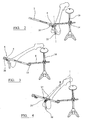
Figures 2 to 4 illustrate use of the instrument in a method for locating the mechanical axis of a patient's femur. -
Figure 5a is an enlarged view of the distal end of the femur shown inFigure 4 , located relative to the point on the bar which is mid-way between the first and second points. -
Figure 5b is an isometric view of the distal end of the femur, with a cutting block located on it. - Referring to the drawings,
Figure 1 shows the instrument which comprises abar 2 which has aslider 4 mounted. As shown inFigure 1 , the slider is located at a first point towards one end of the bar. The slider can be slid tosecond point 6 at the other end of the bar. - The instrument includes a
stand 10, having aconnector arm 8 extending between the stand and the bar. The connector arm is connected to the stand by means of aclamp 12. The height of the connector arm and of the bar on the stand can be adjusted, and fixed against movement by means of a threadedfastener 14 which forms part of the connector. The connector arm is also arranged for rotation around the axis of the stand when the threadedfastener 14 is loosened. In this way, the first end of the bar can be located as desired. The stand has astable tripod base 16, and ahandhold 18 at its upper end so that a user can hold the stand in a stable position. - The
slider 4 can be restrained against sliding movement along thebar 2 by means of a sprungtrigger fastener 20 which can engage detents in the side wall of the bar. The slider might be clamped against sliding movement by means of a threaded fastener. The slider has arod 22 extending vertically from it. The rod is shaped so as to be a snug fit in the inter-condylar notch of a patient's femur. - The
bar 2 has a pair ofholes 24 in its upper face. These can be used to receive fasteners (for example pins or threaded screws) for fastening a cutting block to the bar. Such pins might be used to locate a cutting block which has holes formed in it in which the pins can be received. - Use of the instrument in a procedure for locating the femoral axis of a femur is illustrated in
Figures 2 to 4 . - In a first step, as shown in
Figure 2 , theslider 4 is located at a first end of thebar 2 and clamped in position. With the femur rotated medially through an angle of about 15°, therod 22 is located in the inter-condylar notch, either by moving the stand, or by moving the connector arm relative to the stand once thefastener 14 has been loosened. When therod 22 is located in the inter-condylar notch, the first end of the bar and the rod are clamped against further movement and the stand is stabilised against further movement. - The femur is then rotated laterally through an angle of about 30° as shown in
Figure 3 . After releasing thefastener 20, theslider 4 is slid until the rod engages again the inter-condylar notch. This might require loosening the joint 23 between the connector arm and the bar. When the rod has been located securely in the inter-condylar notch, the joint between the connector arm and the bar is tightened. The joint between the connector arm and the bar can be provided by a pivot pin 21 (which is visible inFigure 1 ) which about which the connector arm or the bar or each of them can pivot. The joint can be tightened by means of a screw which extends through a threadedbore 19 in the connector arm and impinges on the top face of the bar when tightened. -
Figure 4 shows the femur after it has been rotated through an angle of about 15°, so that the distal end of the femur is located approximately midway between the first and second ends of thebar 2. Amarker component 25 is located at the midpoint of the bar, where it is located by means of a pair of fastener pins 27 which are received in theholes 24 in the bar. The marker component includes arod 26 which can be located in the inter-condylar notch. -
Figure 5a is an enlarged view of thebar 2 having amarker component 25 for the third point fitted to it. The marker component can be fastened to the bar using a pair of fastener pins 27, which can be received in theholes 24 which are provided in the bar. - The marker component has a
rod 26 extending from it, and defines a pair of pin holes. In use, the marker component is fitted to the bar with the rod received in the inter-condylar notch.Pins 38 are then inserted into the holes so that the location of the pins in the bone is controlled relative to the mechanical axis of the femur. - In a subsequent step as shown in
Figure 5b , a cuttingguide 40 can be located on the bone using thepins 38 which have previously been inserted into the bone.
Claims (9)
- An instrument adapted to locate an axis of a bone which extends through the centre of rotation of the bone around a joint between that bone and another bone, which comprises:a. a support (2),b. a first marker component (22) adapted to fit to the support at a first point, for engaging the bone in a predetermined position thereon when the bone is located adjacent to the first point, to locate the first end of the support relative to the bone,
in which the first marker component (22) or a separate second marker component is adapted to fit to the support at a second point (6), for engaging the bone in a predetermined position thereon when the bone is moved from its position adjacent to the first point and is located adjacent to the second point, to locate the second point on the support relative to the bone,c. a further marker component (25) adapted to fit to the support at a point which is midway between the first and second points, for engaging the bone in a predetermined position thereon when the bone is in a position which is between its positions adjacent to the first and second points on the support, andd. a clamp (8, 10, 12, 14, 16, 23) adapted to fix the position of the support against movement after the first and second points thereon have been located relative to the bone. - An instrument as claimed in claim 1, in which the first marker component (22) is adapted to be fitted to the support (2) at the first and second ends of the support.
- An instrument as claimed in claim 2, in which the first marker component (22) can be fitted to the support at the first and second ends of the support and is fitted to an element (4) which is adapted to slide along the support (2).
- An instrument as claimed in claim 1, which includes separate first and second marker components adapted to fit to the support (2) at its first and second ends respectively.
- An instrument as claimed in claim 1, in, which at least one of the marker components (22, 25) comprises a rod (22, 26) which is adapted to extend from the support (2) towards the bone.
- An instrument as claimed in claim 5, in which the rod (22, 26) is adapted to slide relative to the support (2) to adjust the length of the rod which extends from the support towards the bone.
- An instrument as claimed in claim 1, in which the clamp includes a stand (10) which extends upwardly from the surface on which the patient lies when the instrument is in use, to which the support (2) is adapted to be connected, directly or indirectly.
- An instrument as claimed in claim 1, which includes an axis rod which extends perpendicularly from the support (2) at the point which is midway between the first and second ends.
- A kit adapted to be used in a procedure for replacing a joint between a first bone and a second bone, said hit comprises an instrument as claimed in claim 1, and a cutting block (40) which is adapted to be located relative to the bone using the instrument.
Applications Claiming Priority (2)
| Application Number | Priority Date | Filing Date | Title |
|---|---|---|---|
| GBGB0622735.9A GB0622735D0 (en) | 2006-11-15 | 2006-11-15 | Locating a bone axis |
| PCT/GB2007/004260 WO2008059211A1 (en) | 2006-11-15 | 2007-11-08 | Locating a bone axis |
Publications (2)
| Publication Number | Publication Date |
|---|---|
| EP2083714A1 EP2083714A1 (en) | 2009-08-05 |
| EP2083714B1 true EP2083714B1 (en) | 2011-12-21 |
Family
ID=37605302
Family Applications (1)
| Application Number | Title | Priority Date | Filing Date |
|---|---|---|---|
| EP07824493A Active EP2083714B1 (en) | 2006-11-15 | 2007-11-08 | Locating a bone axis |
Country Status (5)
| Country | Link |
|---|---|
| US (1) | US9078668B2 (en) |
| EP (1) | EP2083714B1 (en) |
| AT (1) | ATE537764T1 (en) |
| GB (1) | GB0622735D0 (en) |
| WO (1) | WO2008059211A1 (en) |
Families Citing this family (3)
| Publication number | Priority date | Publication date | Assignee | Title |
|---|---|---|---|---|
| US8795282B2 (en) * | 2009-01-29 | 2014-08-05 | Zimmer, Inc. | Apparatus and method for the extramedullary location of the mechanical axis of a femur |
| JP4652481B1 (en) * | 2010-07-29 | 2011-03-16 | 浩一 金粕 | Femoral head center position identification device |
| KR102186793B1 (en) * | 2013-02-08 | 2020-12-04 | 올디오패틱 인터내셔날 인코포레이티드 | System for performing total knee arthroplasty |
Family Cites Families (17)
| Publication number | Priority date | Publication date | Assignee | Title |
|---|---|---|---|---|
| US4952213A (en) * | 1989-02-03 | 1990-08-28 | Boehringer Mannheim Corporation | Tibial cutting guide |
| FR2672488B1 (en) | 1991-02-08 | 1993-05-21 | Fournitures Hospitalieres | SIGHTING INSTRUMENT FOR FEMALE PROSTHESIS. |
| FR2684870B1 (en) | 1991-12-12 | 1994-03-25 | France Bloc | METHOD FOR DETERMINING THE POINT OF ENTRY OF A FEMALE INTRAMEDULAR ROD AND DEVICE FOR VISUALIZING THE POINT OF ENTRY. |
| AU680267B2 (en) * | 1993-06-21 | 1997-07-24 | Howmedica Osteonics Corp. | Method and apparatus for locating functional structures of the lower leg during knee surgery |
| US5474559A (en) * | 1993-07-06 | 1995-12-12 | Zimmer, Inc. | Femoral milling instrumentation for use in total knee arthroplasty with optional cutting guide attachment |
| US5683397A (en) * | 1995-02-15 | 1997-11-04 | Smith & Nephew, Inc. | Distal femoral cutting guide apparatus for use in knee joint replacement surgery |
| US5709689A (en) * | 1995-09-25 | 1998-01-20 | Wright Medical Technology, Inc. | Distal femur multiple resection guide |
| US6090114A (en) | 1997-02-10 | 2000-07-18 | Stryker Howmedica Osteonics Corp. | Tibial plateau resection guide |
| US6344043B1 (en) * | 1997-11-18 | 2002-02-05 | Michael J. Pappas | Anterior-posterior femoral resection guide with set of detachable collets |
| US6629999B1 (en) * | 1999-03-08 | 2003-10-07 | Louis A. Serafin, Jr. | Modular joint |
| US20020133162A1 (en) | 2001-03-17 | 2002-09-19 | Axelson Stuart L. | Tools used in performing femoral and tibial resection in knee surgery |
| US7618421B2 (en) * | 2001-10-10 | 2009-11-17 | Howmedica Osteonics Corp. | Tools for femoral resection in knee surgery |
| AU2003221664A1 (en) * | 2002-04-30 | 2003-11-17 | Orthosoft Inc. | Determining femoral cuts in knee surgery |
| US7427272B2 (en) * | 2003-07-15 | 2008-09-23 | Orthosoft Inc. | Method for locating the mechanical axis of a femur |
| US7862570B2 (en) * | 2003-10-03 | 2011-01-04 | Smith & Nephew, Inc. | Surgical positioners |
| US7803158B2 (en) * | 2004-03-26 | 2010-09-28 | Depuy Products, Inc. | Navigated pin placement for orthopaedic procedures |
| US20060004284A1 (en) * | 2004-06-30 | 2006-01-05 | Frank Grunschlager | Method and system for generating three-dimensional model of part of a body from fluoroscopy image data and specific landmarks |
-
2006
- 2006-11-15 GB GBGB0622735.9A patent/GB0622735D0/en not_active Ceased
-
2007
- 2007-11-08 AT AT07824493T patent/ATE537764T1/en active
- 2007-11-08 WO PCT/GB2007/004260 patent/WO2008059211A1/en not_active Ceased
- 2007-11-08 US US12/515,201 patent/US9078668B2/en active Active
- 2007-11-08 EP EP07824493A patent/EP2083714B1/en active Active
Also Published As
| Publication number | Publication date |
|---|---|
| GB0622735D0 (en) | 2006-12-27 |
| US20100131021A1 (en) | 2010-05-27 |
| US9078668B2 (en) | 2015-07-14 |
| ATE537764T1 (en) | 2012-01-15 |
| EP2083714A1 (en) | 2009-08-05 |
| WO2008059211A8 (en) | 2008-07-31 |
| WO2008059211A1 (en) | 2008-05-22 |
Similar Documents
| Publication | Publication Date | Title |
|---|---|---|
| EP2953561B1 (en) | Instruments for locating a femoral mechanical axis | |
| US6595997B2 (en) | Methods used in performing femoral and tibial resection in knee surgery | |
| US7931655B2 (en) | Methods and tools for femoral resection in knee surgery | |
| US5720752A (en) | Distal femoral cutting guide apparatus with anterior or posterior referencing for use in knee joint replacement surgery | |
| EP2166969B1 (en) | Universal positioning device for orthopedic surgery | |
| US6685711B2 (en) | Apparatus used in performing femoral and tibial resection in knee surgery | |
| US7909831B2 (en) | Systems used in performing femoral and tibial resection in knee surgery | |
| US20060195111A1 (en) | Universal positioning block assembly | |
| US4718413A (en) | Bone cutting guide and methods for using same | |
| US5569261A (en) | Distal femoral cutting guide apparatus with anterior or posterior referencing for use in knee joint replacement surgery | |
| RU2584647C2 (en) | Device for defining a cutting plane for bone resection | |
| US20030018338A1 (en) | Methods and tools for femoral resection in primary knee surgery | |
| US20020133162A1 (en) | Tools used in performing femoral and tibial resection in knee surgery | |
| AU2004200326A1 (en) | Universal alignment guide | |
| JP2000287983A (en) | Thigh bone extramedullary clamp guide device for artificial patella replacing technique | |
| US20190183514A1 (en) | Knee surgery guide and method | |
| CA2537711A1 (en) | Universal positioning block assembly | |
| US9078668B2 (en) | Locating a bone axis | |
| EP1836975B1 (en) | A surgical instrument for locating a cutting plane on a bone | |
| AU2006202002A1 (en) | Universal positioning block assembly |
Legal Events
| Date | Code | Title | Description |
|---|---|---|---|
| PUAI | Public reference made under article 153(3) epc to a published international application that has entered the european phase |
Free format text: ORIGINAL CODE: 0009012 |
|
| 17P | Request for examination filed |
Effective date: 20090403 |
|
| AK | Designated contracting states |
Kind code of ref document: A1 Designated state(s): AT BE BG CH CY CZ DE DK EE ES FI FR GB GR HU IE IS IT LI LT LU LV MC MT NL PL PT RO SE SI SK TR |
|
| DAX | Request for extension of the european patent (deleted) | ||
| 17Q | First examination report despatched |
Effective date: 20100215 |
|
| GRAP | Despatch of communication of intention to grant a patent |
Free format text: ORIGINAL CODE: EPIDOSNIGR1 |
|
| GRAS | Grant fee paid |
Free format text: ORIGINAL CODE: EPIDOSNIGR3 |
|
| GRAA | (expected) grant |
Free format text: ORIGINAL CODE: 0009210 |
|
| AK | Designated contracting states |
Kind code of ref document: B1 Designated state(s): AT BE BG CH CY CZ DE DK EE ES FI FR GB GR HU IE IS IT LI LT LU LV MC MT NL PL PT RO SE SI SK TR |
|
| REG | Reference to a national code |
Ref country code: GB Ref legal event code: FG4D |
|
| REG | Reference to a national code |
Ref country code: CH Ref legal event code: EP |
|
| REG | Reference to a national code |
Ref country code: CH Ref legal event code: NV Representative=s name: E. BLUM & CO. AG PATENT- UND MARKENANWAELTE VSP |
|
| REG | Reference to a national code |
Ref country code: AT Ref legal event code: REF Ref document number: 537764 Country of ref document: AT Kind code of ref document: T Effective date: 20120115 |
|
| REG | Reference to a national code |
Ref country code: IE Ref legal event code: FG4D |
|
| REG | Reference to a national code |
Ref country code: DE Ref legal event code: R096 Ref document number: 602007019567 Country of ref document: DE Effective date: 20120322 |
|
| REG | Reference to a national code |
Ref country code: NL Ref legal event code: VDEP Effective date: 20111221 |
|
| PG25 | Lapsed in a contracting state [announced via postgrant information from national office to epo] |
Ref country code: LT Free format text: LAPSE BECAUSE OF FAILURE TO SUBMIT A TRANSLATION OF THE DESCRIPTION OR TO PAY THE FEE WITHIN THE PRESCRIBED TIME-LIMIT Effective date: 20111221 |
|
| LTIE | Lt: invalidation of european patent or patent extension |
Effective date: 20111221 |
|
| PG25 | Lapsed in a contracting state [announced via postgrant information from national office to epo] |
Ref country code: SE Free format text: LAPSE BECAUSE OF FAILURE TO SUBMIT A TRANSLATION OF THE DESCRIPTION OR TO PAY THE FEE WITHIN THE PRESCRIBED TIME-LIMIT Effective date: 20111221 Ref country code: NL Free format text: LAPSE BECAUSE OF FAILURE TO SUBMIT A TRANSLATION OF THE DESCRIPTION OR TO PAY THE FEE WITHIN THE PRESCRIBED TIME-LIMIT Effective date: 20111221 Ref country code: GR Free format text: LAPSE BECAUSE OF FAILURE TO SUBMIT A TRANSLATION OF THE DESCRIPTION OR TO PAY THE FEE WITHIN THE PRESCRIBED TIME-LIMIT Effective date: 20120322 Ref country code: SI Free format text: LAPSE BECAUSE OF FAILURE TO SUBMIT A TRANSLATION OF THE DESCRIPTION OR TO PAY THE FEE WITHIN THE PRESCRIBED TIME-LIMIT Effective date: 20111221 Ref country code: LV Free format text: LAPSE BECAUSE OF FAILURE TO SUBMIT A TRANSLATION OF THE DESCRIPTION OR TO PAY THE FEE WITHIN THE PRESCRIBED TIME-LIMIT Effective date: 20111221 |
|
| PG25 | Lapsed in a contracting state [announced via postgrant information from national office to epo] |
Ref country code: CY Free format text: LAPSE BECAUSE OF FAILURE TO SUBMIT A TRANSLATION OF THE DESCRIPTION OR TO PAY THE FEE WITHIN THE PRESCRIBED TIME-LIMIT Effective date: 20111221 Ref country code: BE Free format text: LAPSE BECAUSE OF FAILURE TO SUBMIT A TRANSLATION OF THE DESCRIPTION OR TO PAY THE FEE WITHIN THE PRESCRIBED TIME-LIMIT Effective date: 20111221 |
|
| PG25 | Lapsed in a contracting state [announced via postgrant information from national office to epo] |
Ref country code: SK Free format text: LAPSE BECAUSE OF FAILURE TO SUBMIT A TRANSLATION OF THE DESCRIPTION OR TO PAY THE FEE WITHIN THE PRESCRIBED TIME-LIMIT Effective date: 20111221 Ref country code: CZ Free format text: LAPSE BECAUSE OF FAILURE TO SUBMIT A TRANSLATION OF THE DESCRIPTION OR TO PAY THE FEE WITHIN THE PRESCRIBED TIME-LIMIT Effective date: 20111221 Ref country code: EE Free format text: LAPSE BECAUSE OF FAILURE TO SUBMIT A TRANSLATION OF THE DESCRIPTION OR TO PAY THE FEE WITHIN THE PRESCRIBED TIME-LIMIT Effective date: 20111221 Ref country code: IS Free format text: LAPSE BECAUSE OF FAILURE TO SUBMIT A TRANSLATION OF THE DESCRIPTION OR TO PAY THE FEE WITHIN THE PRESCRIBED TIME-LIMIT Effective date: 20120421 Ref country code: BG Free format text: LAPSE BECAUSE OF FAILURE TO SUBMIT A TRANSLATION OF THE DESCRIPTION OR TO PAY THE FEE WITHIN THE PRESCRIBED TIME-LIMIT Effective date: 20120321 |
|
| PG25 | Lapsed in a contracting state [announced via postgrant information from national office to epo] |
Ref country code: RO Free format text: LAPSE BECAUSE OF FAILURE TO SUBMIT A TRANSLATION OF THE DESCRIPTION OR TO PAY THE FEE WITHIN THE PRESCRIBED TIME-LIMIT Effective date: 20111221 Ref country code: PL Free format text: LAPSE BECAUSE OF FAILURE TO SUBMIT A TRANSLATION OF THE DESCRIPTION OR TO PAY THE FEE WITHIN THE PRESCRIBED TIME-LIMIT Effective date: 20111221 Ref country code: PT Free format text: LAPSE BECAUSE OF FAILURE TO SUBMIT A TRANSLATION OF THE DESCRIPTION OR TO PAY THE FEE WITHIN THE PRESCRIBED TIME-LIMIT Effective date: 20120423 |
|
| REG | Reference to a national code |
Ref country code: AT Ref legal event code: MK05 Ref document number: 537764 Country of ref document: AT Kind code of ref document: T Effective date: 20111221 |
|
| PLBE | No opposition filed within time limit |
Free format text: ORIGINAL CODE: 0009261 |
|
| STAA | Information on the status of an ep patent application or granted ep patent |
Free format text: STATUS: NO OPPOSITION FILED WITHIN TIME LIMIT |
|
| PG25 | Lapsed in a contracting state [announced via postgrant information from national office to epo] |
Ref country code: DK Free format text: LAPSE BECAUSE OF FAILURE TO SUBMIT A TRANSLATION OF THE DESCRIPTION OR TO PAY THE FEE WITHIN THE PRESCRIBED TIME-LIMIT Effective date: 20111221 |
|
| 26N | No opposition filed |
Effective date: 20120924 |
|
| PG25 | Lapsed in a contracting state [announced via postgrant information from national office to epo] |
Ref country code: IT Free format text: LAPSE BECAUSE OF FAILURE TO SUBMIT A TRANSLATION OF THE DESCRIPTION OR TO PAY THE FEE WITHIN THE PRESCRIBED TIME-LIMIT Effective date: 20111221 |
|
| REG | Reference to a national code |
Ref country code: DE Ref legal event code: R097 Ref document number: 602007019567 Country of ref document: DE Effective date: 20120924 |
|
| PG25 | Lapsed in a contracting state [announced via postgrant information from national office to epo] |
Ref country code: AT Free format text: LAPSE BECAUSE OF FAILURE TO SUBMIT A TRANSLATION OF THE DESCRIPTION OR TO PAY THE FEE WITHIN THE PRESCRIBED TIME-LIMIT Effective date: 20111221 |
|
| PG25 | Lapsed in a contracting state [announced via postgrant information from national office to epo] |
Ref country code: ES Free format text: LAPSE BECAUSE OF FAILURE TO SUBMIT A TRANSLATION OF THE DESCRIPTION OR TO PAY THE FEE WITHIN THE PRESCRIBED TIME-LIMIT Effective date: 20120401 |
|
| PG25 | Lapsed in a contracting state [announced via postgrant information from national office to epo] |
Ref country code: FI Free format text: LAPSE BECAUSE OF FAILURE TO SUBMIT A TRANSLATION OF THE DESCRIPTION OR TO PAY THE FEE WITHIN THE PRESCRIBED TIME-LIMIT Effective date: 20111221 |
|
| PG25 | Lapsed in a contracting state [announced via postgrant information from national office to epo] |
Ref country code: MT Free format text: LAPSE BECAUSE OF FAILURE TO SUBMIT A TRANSLATION OF THE DESCRIPTION OR TO PAY THE FEE WITHIN THE PRESCRIBED TIME-LIMIT Effective date: 20111221 |
|
| PG25 | Lapsed in a contracting state [announced via postgrant information from national office to epo] |
Ref country code: MC Free format text: LAPSE BECAUSE OF NON-PAYMENT OF DUE FEES Effective date: 20121130 Ref country code: TR Free format text: LAPSE BECAUSE OF FAILURE TO SUBMIT A TRANSLATION OF THE DESCRIPTION OR TO PAY THE FEE WITHIN THE PRESCRIBED TIME-LIMIT Effective date: 20111221 |
|
| PG25 | Lapsed in a contracting state [announced via postgrant information from national office to epo] |
Ref country code: LU Free format text: LAPSE BECAUSE OF NON-PAYMENT OF DUE FEES Effective date: 20121108 |
|
| PG25 | Lapsed in a contracting state [announced via postgrant information from national office to epo] |
Ref country code: HU Free format text: LAPSE BECAUSE OF FAILURE TO SUBMIT A TRANSLATION OF THE DESCRIPTION OR TO PAY THE FEE WITHIN THE PRESCRIBED TIME-LIMIT Effective date: 20071108 |
|
| REG | Reference to a national code |
Ref country code: FR Ref legal event code: PLFP Year of fee payment: 10 |
|
| REG | Reference to a national code |
Ref country code: FR Ref legal event code: PLFP Year of fee payment: 11 |
|
| REG | Reference to a national code |
Ref country code: FR Ref legal event code: PLFP Year of fee payment: 12 |
|
| PGFP | Annual fee paid to national office [announced via postgrant information from national office to epo] |
Ref country code: FR Payment date: 20250930 Year of fee payment: 19 |
|
| REG | Reference to a national code |
Ref country code: CH Ref legal event code: U11 Free format text: ST27 STATUS EVENT CODE: U-0-0-U10-U11 (AS PROVIDED BY THE NATIONAL OFFICE) Effective date: 20251201 |
|
| PGFP | Annual fee paid to national office [announced via postgrant information from national office to epo] |
Ref country code: DE Payment date: 20250930 Year of fee payment: 19 |
|
| PGFP | Annual fee paid to national office [announced via postgrant information from national office to epo] |
Ref country code: GB Payment date: 20251001 Year of fee payment: 19 |
|
| PGFP | Annual fee paid to national office [announced via postgrant information from national office to epo] |
Ref country code: CH Payment date: 20251201 Year of fee payment: 19 |
|
| PGFP | Annual fee paid to national office [announced via postgrant information from national office to epo] |
Ref country code: IE Payment date: 20251001 Year of fee payment: 19 |