EP2083446B1 - Appareil de capture d'image - Google Patents
Appareil de capture d'image Download PDFInfo
- Publication number
- EP2083446B1 EP2083446B1 EP09151492A EP09151492A EP2083446B1 EP 2083446 B1 EP2083446 B1 EP 2083446B1 EP 09151492 A EP09151492 A EP 09151492A EP 09151492 A EP09151492 A EP 09151492A EP 2083446 B1 EP2083446 B1 EP 2083446B1
- Authority
- EP
- European Patent Office
- Prior art keywords
- image pickup
- image
- section
- microlenses
- pickup device
- Prior art date
- Legal status (The legal status is an assumption and is not a legal conclusion. Google has not performed a legal analysis and makes no representation as to the accuracy of the status listed.)
- Expired - Fee Related
Links
- 238000012545 processing Methods 0.000 claims description 85
- 238000012937 correction Methods 0.000 claims description 43
- 238000000034 method Methods 0.000 claims description 31
- 230000008569 process Effects 0.000 claims description 25
- 230000007547 defect Effects 0.000 claims description 9
- 230000009467 reduction Effects 0.000 claims description 5
- 239000003086 colorant Substances 0.000 description 6
- 230000000052 comparative effect Effects 0.000 description 6
- 238000010586 diagram Methods 0.000 description 4
- 239000011159 matrix material Substances 0.000 description 3
- 230000003287 optical effect Effects 0.000 description 3
- 238000001514 detection method Methods 0.000 description 2
- 230000035945 sensitivity Effects 0.000 description 2
- 230000005856 abnormality Effects 0.000 description 1
- 230000004075 alteration Effects 0.000 description 1
- 230000005540 biological transmission Effects 0.000 description 1
- 230000000295 complement effect Effects 0.000 description 1
- 238000013461 design Methods 0.000 description 1
- 230000000694 effects Effects 0.000 description 1
- 230000002708 enhancing effect Effects 0.000 description 1
- 238000005286 illumination Methods 0.000 description 1
- 239000007788 liquid Substances 0.000 description 1
- 239000004973 liquid crystal related substance Substances 0.000 description 1
- 229910044991 metal oxide Inorganic materials 0.000 description 1
- 150000004706 metal oxides Chemical class 0.000 description 1
- 238000000386 microscopy Methods 0.000 description 1
- 238000012986 modification Methods 0.000 description 1
- 230000004048 modification Effects 0.000 description 1
- 238000011946 reduction process Methods 0.000 description 1
- 239000004065 semiconductor Substances 0.000 description 1
- 230000003595 spectral effect Effects 0.000 description 1
Images


Classifications
-
- H—ELECTRICITY
- H01—ELECTRIC ELEMENTS
- H01L—SEMICONDUCTOR DEVICES NOT COVERED BY CLASS H10
- H01L27/00—Devices consisting of a plurality of semiconductor or other solid-state components formed in or on a common substrate
- H01L27/14—Devices consisting of a plurality of semiconductor or other solid-state components formed in or on a common substrate including semiconductor components sensitive to infrared radiation, light, electromagnetic radiation of shorter wavelength or corpuscular radiation and specially adapted either for the conversion of the energy of such radiation into electrical energy or for the control of electrical energy by such radiation
- H01L27/144—Devices controlled by radiation
- H01L27/146—Imager structures
- H01L27/14601—Structural or functional details thereof
- H01L27/14625—Optical elements or arrangements associated with the device
- H01L27/14627—Microlenses
-
- H—ELECTRICITY
- H04—ELECTRIC COMMUNICATION TECHNIQUE
- H04N—PICTORIAL COMMUNICATION, e.g. TELEVISION
- H04N23/00—Cameras or camera modules comprising electronic image sensors; Control thereof
- H04N23/80—Camera processing pipelines; Components thereof
-
- H—ELECTRICITY
- H04—ELECTRIC COMMUNICATION TECHNIQUE
- H04N—PICTORIAL COMMUNICATION, e.g. TELEVISION
- H04N23/00—Cameras or camera modules comprising electronic image sensors; Control thereof
- H04N23/80—Camera processing pipelines; Components thereof
- H04N23/84—Camera processing pipelines; Components thereof for processing colour signals
- H04N23/843—Demosaicing, e.g. interpolating colour pixel values
-
- H—ELECTRICITY
- H04—ELECTRIC COMMUNICATION TECHNIQUE
- H04N—PICTORIAL COMMUNICATION, e.g. TELEVISION
- H04N25/00—Circuitry of solid-state image sensors [SSIS]; Control thereof
- H04N25/10—Circuitry of solid-state image sensors [SSIS]; Control thereof for transforming different wavelengths into image signals
- H04N25/11—Arrangement of colour filter arrays [CFA]; Filter mosaics
- H04N25/13—Arrangement of colour filter arrays [CFA]; Filter mosaics characterised by the spectral characteristics of the filter elements
- H04N25/134—Arrangement of colour filter arrays [CFA]; Filter mosaics characterised by the spectral characteristics of the filter elements based on three different wavelength filter elements
-
- H—ELECTRICITY
- H01—ELECTRIC ELEMENTS
- H01L—SEMICONDUCTOR DEVICES NOT COVERED BY CLASS H10
- H01L27/00—Devices consisting of a plurality of semiconductor or other solid-state components formed in or on a common substrate
- H01L27/14—Devices consisting of a plurality of semiconductor or other solid-state components formed in or on a common substrate including semiconductor components sensitive to infrared radiation, light, electromagnetic radiation of shorter wavelength or corpuscular radiation and specially adapted either for the conversion of the energy of such radiation into electrical energy or for the control of electrical energy by such radiation
- H01L27/144—Devices controlled by radiation
- H01L27/146—Imager structures
- H01L27/14601—Structural or functional details thereof
- H01L27/1462—Coatings
- H01L27/14623—Optical shielding
-
- H—ELECTRICITY
- H04—ELECTRIC COMMUNICATION TECHNIQUE
- H04N—PICTORIAL COMMUNICATION, e.g. TELEVISION
- H04N23/00—Cameras or camera modules comprising electronic image sensors; Control thereof
- H04N23/10—Cameras or camera modules comprising electronic image sensors; Control thereof for generating image signals from different wavelengths
-
- H—ELECTRICITY
- H04—ELECTRIC COMMUNICATION TECHNIQUE
- H04N—PICTORIAL COMMUNICATION, e.g. TELEVISION
- H04N25/00—Circuitry of solid-state image sensors [SSIS]; Control thereof
- H04N25/60—Noise processing, e.g. detecting, correcting, reducing or removing noise
- H04N25/68—Noise processing, e.g. detecting, correcting, reducing or removing noise applied to defects
Definitions
- the present invention contains subject matter related to Japanese Patent Application JP 2008-016716 filed in the Japanese Patent Office on January 28, 2008.
- the present invention relates to an image pickup apparatus using a microlens array.
- image pickup apparatuses using a technique called “Light Field Photography”.
- Such an image pickup apparatus includes an image pickup lens, a microlens array, an image pickup device and an image processing section, and an aperture stop including a single aperture in its central part is included in the image pickup lens.
- image pickup data obtained by the image pickup device includes the intensity distribution of light on a light-sensing plane as well as information on the traveling direction of the light.
- the image processing section is capable of reconstructing or reproducing an image viewed from an arbitrary viewpoint or an arbitrary direction (hereinafter simply referred to as a field of view).
- Document WO 2007/044725A2 discloses microscopy arrangements, wherein a subject is imaged by passing light from the subject through a microlens array to a photosensor array to simultaneously detect light from the subject that is passed through different directions to different locations.
- the number of pixels in a reconstructed image is equal to the number of microlenses in the microlens array, because information on the two-dimensional coordinates of the reconstructed image is determined by the coordinates of the microlens array. Therefore, the number of pixels in the two-dimensional coordinates of the reconstructed image is equal to the number determined by dividing the total number of pixels of the image pickup device by the number of pixels allocated to each microlens.
- the number of pixels allocated to each microlens is equal to the resolution of the angular information of a light ray, and determines the resolution in an arbitrary field of view of the reconstructed image, that is, determines the number of viewpoints or directions from which an image is reconstructed. Therefore, there is a trade-off relationship between the resolution in the arbitrary field of view and the number of pixels in two-dimensional coordinates.
- the image pickup data includes the intensity distribution of light as well as the information on the traveling direction of the light, so it is important to describe each light ray separately.
- the pitch between images each corresponding to each of microlenses images formed by projecting an aperture stop of a main lens, for example, circular images
- the number of pixels allocated to each microlens changes depending on the position of the aperture stop of the main lens. Therefore, in some cases, depending on the position of the aperture stop, it is difficult to obtain a reconstructed image such as a refocused image and the arbitrary viewpoint image as an image unique to the above-described technique.
- an image of an object subjected to image pickup by the image pickup lens section is formed on the microlens array section. Then, a light ray entering into the microlens array section reaches the image pickup device, and is detected by a plurality of image pickup pixels allocated to each of the microlenses, thereby image pickup data including information on the traveling direction of light is obtained.
- image pickup data including information on the traveling direction of light is obtained.
- a second image pickup apparatus including: an image pickup lens section having an aperture stop; an image pickup device obtaining image pickup data on the basis of light detected; a microlens array section arranged on a focal plane of the image pickup lens section between the image pickup lens section and the image pickup device, and including a plurality of microlenses, each of the microlenses being provided corresponding to a plurality of image pickup pixels of the image pickup device; and an image height correction section performing image height correction on the image pickup data obtained by the image pickup device so that an image size, in a predetermined direction, of an image formed on the image pickup device by a single microlens is equal to an integral multiple of a pixel size, in the predetermined direction, of the image pickup pixel.
- an image of an object subjected to image pickup by the image pickup lens section is formed on the microlens array section. Then, a light ray entering into the microlens array reaches the image pickup device, and is detected by a plurality of image pickup pixels allocated to each of the microlenses, thereby image pickup data including information on the traveling direction of light is obtained.
- the image height correction section performs image height correction on the image pickup data obtained by the image pickup device so that an image size, in a predetermined direction, of an image formed on the image pickup device by a single microlens is equal to an integral multiple of a pixel size, in the predetermined direction, of the image pickup pixel, so irrespective of the position of the aperture stop, image height deviation in a light-sensing plane of the image pickup device is prevented from occurring in image pickup data obtained by performing such image height correction.
- the pitch between the microlenses satisfies the above-described formula, so image height deviation in the light-sensing plane of the image pickup device may be prevented from occurring in image pickup data obtained by the image pickup device. Therefore, when a reconstructed image is formed through the use of such image pickup data, in the case where image pickup data is obtained so as to include information on the traveling direction of light, an appropriate reconstructed image may be formed.
- the image height correction section performs image height correction on the image pickup data obtained by the image pickup device so that an image size, in the predetermined direction, of an image formed on the image pickup device by a single microlens is equal to an integral multiple of a pixel size, in the predetermined direction, of the image pickup pixel, so irrespective of the position of the aperture stop, image height deviation in a light-sensing plane of the image pickup device may be prevented from occurring in image pickup data obtained by performing image height correction.
- FIG. 1 illustrates the whole configuration of an image pickup apparatus (an image pickup apparatus 1) according to a first embodiment of the invention.
- the image pickup apparatus 1 picks up an image of an object 2 to output image pickup data Dout.
- the image pickup apparatus 1 includes an image pickup lens 11, an aperture stop 10, a microlens array 12 and an image pickup device 13 in order from a side closer to the object 2.
- the image pickup apparatus 1 also includes an image processing section 14, an image pickup device driving section 15 and a control section 16.
- the image pickup lens 11 is a main lens for picking up an image of an object, and includes, for example, a typical image pickup lens used in a video camera, a still camera or the like.
- the aperture stop 10 is an optical aperture stop of the image pickup lens 11.
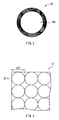
- the aperture stop 10 has one circular aperture section 10A in its central part. Thereby, as will be described in detail later, all light rays passing through the aperture stop 10A keep information on the traveling direction thereof.
- the aperture stop 10 and the microlens array 12 are arranged to have a distance L therebetween.
- each microlens 12-1 is two-dimensionally arranged in a matrix form (the pitch between the microlenses 12-1: p12), and the microlens array 12 is arranged on an image forming plane of the image pickup lens 11 (a reference numeral f1 in the drawing donates the focal length of the image pickup lens 11).
- the planar shape of each microlens 12-1 is circular, and each microlens 12-1 is made of, for example, a liquid crystal lens, a liquid lens, a diffractive lens or the like.
- the pitch between the microlenses 12-1 is "p12" as described above
- the pixel size in a predetermined direction of an image pickup pixel (a pixel P which will be described later) of the image pickup device 13 is "s”
- the number of pixels P allocated to each microlens 12-1 in the predetermined direction is "m” (an integer)
- the pitch p12 between the microlenses 12-1 is represented by the following formula (11).
- the image pickup device 13 receives or detects light from the microlens array 12 to obtain image pickup data D0, and is arranged on the focal plane of the microlens array 12 (a reference numeral f2 in the drawing donates the focal length of each of the microlenses 12-1).
- the image pickup device 13 includes a two-dimensional image pickup device such as a plurality of CCDs (Charge Coupled Devices) or a plurality of CMOSs (Complementary Metal-Oxide Semiconductors) two-dimensionally arranged in a matrix form.
- M ⁇ N M and N each are an integer
- number of image pickup pixels pixels P which will be described later
- the number (m ⁇ n) of pixels allocated to each microlens 12-1 is related to the resolution in an arbitrary field of view of a reconstructed image, so the resolution in the arbitrary field of view of the reconstructed image increases with an increase in the values of m and n.
- the values of (M/m) and (N/n) are related to the number of pixels (the resolution) in the reconstructed image, so the number of pixels in the reconstructed image increases with an increase in the values of (M/m) and (N/n). Therefore, there is a trade-off relationship between the resolution in the arbitrary field of view of the reconstructed image and the number of pixels.
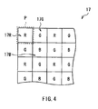
- a color filter 17 as illustrated in FIG. 4 is two-dimensionally arranged for each pixel P (not illustrated in FIG. 1 ).
- Such a color filter 17 is arranged on the light-sensing plane of the image pickup device 13, thereby the image pickup data D0 obtained by the image pickup device 13 becomes pixel data (color pixel data) of a plurality of colors (in this case, three primary colors) corresponding to the colors of the color filter 17.
- the image processing section 14 performs predetermined image processing which will be described later (image processing including a sorting process) on the image pickup data D0 obtained by the image pickup device 13, and outputs image pickup data Dout obtained by performing the image processing. More specifically, for example, the image processing section 14 performs refocusing arithmetic processing utilizing a technique called "Light Field Photography". Thereby, the image processing section 14 may form an image (a reconstructed image on the basis of the image pickup data Dout) focused on an arbitrary focal point.
- the configuration of the image processing section 14 and the operation of refocusing arithmetic processing will be described in detail later.
- the image pickup device driving section 15 drives the image pickup device 13, and controls the light-sensing operation of the image pickup device 13.
- the control section 16 controls the operations of the image processing section 14 and the image pickup device driving section 15, and includes, for example, a microcomputer or the like.
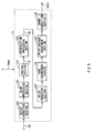
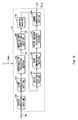
- FIG. 5 illustrates a functional block diagram of the image processing section 14.
- the image processing section 14 includes a defect correction section 141, a clamp processing section 142, an interpolation processing section 143, a sorting section 144, a noise reduction section 145, an edge enhancement section 146, a white balance adjustment section 147 and a gamma correction section 148.
- the defect correction section 141 corrects a defect such as loss or invalidity included in the image pickup data D0 (a defect caused by an abnormality in the image pickup device 13).
- the clamp processing section 142 performs a process (clamp processing) of setting the black level of each pixel data on image pickup data obtained through the defect correction by the defect correction section 142.
- the interpolation processing section 143 performs interpolation processing on image pickup data supplied from the clamp processing section 142, for example, a demosaic process or the like on a typical Bayer arrangement so as to obtain image pickup data D1.
- the sorting section 144 performs a predetermined sorting process (a process of sorting pixel data) on the image pickup data D1 supplied from the interpolation processing section 143 so as to obtain image pickup data D2.
- a predetermined sorting process a process of sorting pixel data
- the noise reduction section 145 performs a process of reducing noise (for example, noise generated when an image is picked up in a dark place or a place with insufficient sensitivity) included in the image pickup data D2 supplied from the sorting section 144.
- the edge enhancement section 146 performs an edge enhancement process, that is, a process of enhancing the edge of an image on image pickup data supplied from the noise reduction section 145.
- the white balance adjustment section 147 performs a process (a white balance adjustment process) of adjusting color balance on image pickup data supplied from the edge enhancement section 146 (image pickup data adjusted or set so that the number of red pixel data, green pixel data and blue pixel data are equal to one another), where such color balance may be affected by an individual difference among devices such as a difference in spectral sensitivity of the image pickup device 13, by a difference in transmission characteristics of the color filter 17 or by illumination conditions.
- the gamma correction section 148 performs predetermined gamma correction (tone or contrast correction) on image pickup data supplied from the white balance adjustment section 147 so as to obtain image pickup data Dout.
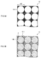
- an image of the object 2 by the image pickup lens 11 is formed on the microlens array 12 in accordance with the shape (the circular shape) of each microlens 12-1 as illustrated in FIG. 6A , for example. Then, an incident light ray to the microlens array 12 reaches the image pickup device 13 through the microlens array 12, and, for example, as illustrated in FIG. 6B , the incident light ray is detected by a light-sensing region 13-1 on which the circular shape of the aperture stop 10 is projected, and the image pickup data D0 is obtained by the image pickup device 13.
- the incident light ray to the microlens array 12 is detected in a different position in the image pickup device 13 according to the incident direction of the incident light ray. More specifically, the incident direction of the light ray is determined by the positions of the pixels P allocated to each microlens 12-1.
- a region (a reconstructed pixel region 13D) where the pixels P allocated to each microlens 12-1 are arranged corresponds to one pixel of the reconstructed image.
- the image pickup data obtained in the image pickup device 13 is inputted into the image processing section 14. Then, in the image processing section 14, predetermined image processing (for example, the above-described refocusing arithmetic processing) is performed on the image pickup data D0, thereby the image pickup data Dout obtained through the image processing is outputted as output data (image data of the reconstructed image) of the image pickup apparatus 1.
- predetermined image processing for example, the above-described refocusing arithmetic processing
- a rectangular coordinate system (u, v) is defined on an image pickup lens plane of the image pickup lens 11, and a rectangular coordinate system (x, y) is defined on an image pickup plane of the image pickup device 13.
- a distance between the image pickup lens plane of the image pickup lens 11 and the image pickup plane of the image pickup device 13 is defined as "F”.
- a light ray L1 passing through the image pickup lens 11 and the image pickup device 13 is represented by a four-dimensional function L F (x, y, u, v). Therefore, information on the traveling direction of the light ray L1 as well as information on the position of the light ray L1 is recorded into the image pickup device 13.
- the incident direction of the light ray is determined by the arrangement of the plurality of pixels P allocated to each microlens 12-1.
- detection intensity L F' on the image pickup plane 130 of coordinates (s, t) on the refocus plane 120 is represented by the following formula (12).
- an image E F' (s, t) obtained on the refocus plane 120 is a value obtained by integrating the above-described detection intensity L F' with respect to a lens aperture, so the image E F' (s, t) is represented by the following formula (13). Therefore, when a refocusing arithmetic operation is performed on the basis of the formula (13), on the basis of the image pickup data Dout obtained through the image processing, an image focused on an arbitrary focal point (the refocus plane 120) is reconstructed.
- the defect correction section 141 corrects a defect in the image pickup data D0 supplied from the image pickup device 13, and the clamping processing section 142 performs clamp processing on the image pickup data D0. Then, the interpolation processing section 143 performs interpolation processing on the image pickup data D0, and the sorting section 144 performs the sorting process of the pixel data D1. Thereby the image pickup data D2 is produced from the image pickup data D1.
- the light ray which is once condensed is dispersed again, and passes through a different microlens array depending on its traveling direction to reach the image pickup device 13. Therefore, for example, as illustrated in FIG. 11 , a process of sorting each pixel data is performed such that pixel data D10 corresponding to such a light ray is selectively extracted from a plurality of mutually-different reconstructed pixel regions 13D.
- a sorting process of each pixel data is performed such that pixel data D10 corresponding to such a light ray is selectively extracted from a plurality of mutually-different reconstructed pixel regions 13D.
- the noise reduction section 145 further performs a noise reduction process on the image pickup data D2 obtained through such a sorting process, and the edge enhancement section 146 performs the edge enhancement process on the image pickup data D2, and then the image pickup data D2 is supplied to the white balance adjustment section 147. Thereby, image pickup data of which color balance is adjusted is obtained.
- the gamma correction section 148 performs the gamma correction on the image pickup data supplied from the white balance adjustment section 147, thereby the image pickup data is outputted from the image processing section 14 as the image pickup data Dout. Thereby, an image focused on an arbitrary focal point (the refocus plane 120) is reconstructed on the basis of the image pickup data Dout.
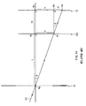
- FIGs. 13 and 14 illustrate a state of image pickup in the case where image height deviation occurs (the case of the image height deviation amount ⁇ >0) in an image pickup apparatus according to the comparative example (including a microlens array 102 in which the pitch p12 between the microlenses 12-1 does not satisfy the above-described formula (1), instead of the microlens array 12 in the image pickup apparatus 1).
- the pitch between images (unit images) formed on the image pickup device 13 in accordance with the shapes (circular shapes) of the microlenses 12-1 is shifted from a position P1 to a position P2 as indicated by an arrow in the drawing, depending on the position of the aperture stop 10.
- the image height deviation by an image height deviation amount ⁇ (a distance between a point Pd and a point Pe) occurs in the light-sensing plane (a plane on a side closer to the microlens array 12) of the image pickup device 13.
- the image height deviation amount ⁇ is represented by the following formulas (14) and (15), where an inclined angle between the optical axis and the main light ray L0 is " ⁇ ", an image height (a distance between a point Pb and a point Pf) of an image of the main light ray L0 formed on the microlens array 102 is "y”, a distance between the aperture stop 10 and the microlens array 12 (a distance between a point Pa and the point Pb) is "L”, and the focal length of each of the microlenses 12-1 (a distance between the point Pb and a point Pc) is "f2".
- a ratio between the image height y on the microlens array 12 and the image height of a unit image formed on the image pickup device 13 (a distance between the point Pc and the point Pe) is represented by the following formula (16).
- the pitch p12 between the microlenses 12-1 in the microlens array 102 does not satisfy the above-described formula (11), the image height deviation by the image height deviation amount ⁇ represented by the above-described formulas (14) and (15) consequently occurs.
- the pitch p12 between the microlenses 12-1 is not equal to an integral multiple of the pixel P of the image pickup device 13. Therefore, the number of pixels P allocated to each of the microlenses 12-1 in a predetermined direction changes, and in the image processing section 14, a reconstructed image such as a refocused image or an arbitrary viewpoint image may not be obtained.
- the pitch p12 between the microlenses 12-1 satisfies the above-described formula (11).
- the value of an image height correction factor (corresponding to an inverse of the above-described formula (16)) according to the above-described comparative example is constantly "1". Therefore, in the image pickup data D0 obtained by the image pickup device 13, the occurrence of image height deviation (image height deviation by the image height deviation amount ⁇ ) in the light-sensing plane (a plane on a side closer to the microlens array 12) of the image pickup device 13 is prevented.
- the pitch p12 between the microlenses 12-1 satisfies the above-described formula (11).
- the occurrence of image height deviation in the light-sensing plane of the image pickup device 13 may be prevented. Therefore, when a reconstructed image is formed by the image processing section 14 through the use of such image pickup data D0, an appropriate reconstructed image may be formed in the case where image pickup data is obtained in such a manner as to include information on the traveling direction of light.
- an image height correction section (an image height correction section 149 which will be described later) performing image height correction
- the present embodiment is achieved only by setting the pitch p12 between the microlenses 12-1, so unless otherwise the position of the aperture stop 10 determined when designing the pitch between the microlenses 12-1 is displaced, an appropriate reconstructed image is formed easily.
- An image pickup apparatus has the same configuration as that of the image pickup apparatus according to the first embodiment, except that the image pickup apparatus according to the present embodiment includes an image processing section 14A which will be described below instead of the image processing section 14 of the image pickup apparatus according to the first embodiment, and that a microlens array (corresponding to the above-described microlens array 102) in which the pitch p12 between the microlenses 12-1 does not satisfy the above-described formula (1) is provided instead of the microlens array 12. Therefore, like components are denoted by like numerals as of the first embodiment, and will not be further described.
- FIG. 15 illustrates a functional block diagram of an image processing section (an image processing section 14A) used in the image pickup apparatus according to the present embodiment.
- the image processing section 14A differs from the image processing section 14 described in the first embodiment, in a configuration that an image height correction section 149 is arranged between the interpolation processing section 143 and the sorting section 144.
- the image height correction section 149 performs image height correction on the image pickup data obtained by the image pickup device 13 (more specifically image pickup data D1 obtained by performing interpolation processing by the interpolation processing section 143), so that an image size in a predetermined direction (corresponding to the pitch p12 between the microlenses 12-1) of an image (a unit image) formed on the image pickup device 13 by a single microlens 12-1 is equal to an integral multiple of the pixel size s in the predetermined direction of the pixel P of the image pickup device 13.
- image pickup data D3 is obtained through the image height correction, and the image pickup data D3 is supplied to the sorting section 144.
- the image height correction section 149 performs image height correction on the image pickup data D1 through the use of a correction factor k represented by the following formulas (17) and (18) (the image height correction section 149 obtains the image pickup data D3 by multiplying the image pickup data D1 by the correction factor k).
- a correction factor k represented by the following formulas (17) and (18)
- the image height correction section 149 performs the image height correction on the image pickup data D1 so that an image size in a predetermined direction (corresponding to the pitch p12 between the microlenses 12-1) of an image (a unit image) formed on the image pickup device 13 by a single microlens 12-1 is equal to an integral multiple of the pixel size s in the predetermined direction of the pixel P.
- the pitch p12 between the microlenses 12-1 satisfies the above-described formula (11)
- image height correction is performed by the image height correction section 149
- the configurations described in the first and second embodiments may be combined. More specifically, the pitch p12 between the microlenses 12-1 may satisfy the above-described formula (11), as well as the image height correction may be performed by the image height correction section 149.
- the image processing sections 14 and 14A are described as components of the image pickup apparatus.
- the image processing section is not necessarily arranged in the image pickup apparatus. More specifically, the image processing section may be arranged in an apparatus other than the image pickup apparatus, for example, a PC (Personal Computer) or the like, and image pickup data obtained in the image pickup apparatus may be transferred to the PC to perform image processing on the image pickup data in the PC.
- a PC Personal Computer
- the aperture stop is arranged on an image side of the image pickup lens (an exit side).
- the invention is not limited to this, and the aperture stop may be arranged on an object side of the image pickup lens (an incident side) or in the image pickup lens.
- a color filter having any other arrangement may be used.
- demosaic process is described as an example of the interpolation processing of pixel data in the image pickup data.
- any other interpolation processing may be performed.
- the image processing including the sorting process performed in the image processing section 14 the refocusing arithmetic processing using the "Light Field Photography" is described.
- the image processing including such a sorting process is not limited to this, and, for example, focus blur processing, depth of field adjustment processing or the like may be used.
Claims (4)
- Appareil de capture d'image (1) comprenant :une section de lentille de capture d'image (11) comportant un diaphragme d'ouverture (10) ;un dispositif de capture d'image (13) permettant d'obtenir des données de capture d'image sur la base de la lumière détectée ; etune section de réseau de microlentilles (12) agencée dans le plan focal de la section de lentille de capture d'image (11) entre la section de lentille de capture d'image (11) et le dispositif de capture d'image (13), et incluant une pluralité de microlentilles identiques (12-1), chacune des microlentilles (12-1) ayant une forme plane circulaire et étant disposée d'une manière correspondant à une pluralité de pixels de capture d'image du dispositif de capture d'image (13),dans lequel la formule (1) suivante est satisfaite :
 où p est le pas entre les microlentilles voisines (12-1), s est la dimension d'un pixel dans une direction prédéterminée, correspondant à la direction considérée pour le pas des microlentilles (12-1), m est le nombre entier de pixels de capture d'image alloués à chacune des microlentilles (12-1) dans la direction prédéterminée, L est la distance entre le diaphragme d'ouverture (10) et la section de réseau de microlentilles (12) et f est la longueur focale de chacune des microlentilles (12-1).
 - Appareil de capture d'image selon la revendication 1, comprenant en outre :une section de traitement d'image (14) configurée pour effectuer un traitement d'image incluant un processus de tri sur les données de capture d'image obtenues par le dispositif de capture d'image (13).
- Appareil de capture d'image selon la revendication 2, dans lequel celui-ci comprend une section de traitement d'image (14) configurée pour effectuer un traitement arithmétique de refocalisation sur les données de capture d'image obtenues par le dispositif de capture d'image (13).
- Appareil de capture d'image selon la revendication 2 ou la revendication 3, dans lequel ladite section de traitement d'image (14) comprend une section de correction de défaut (141), une section de traitement de calage (142), une section de tri (143), une section de traitement d'interpolation (144), une section de réduction de bruit (145), une section de renforcement des contours (146), une section de réglage d'équilibre des blancs (147) et une section de correction de gamma (148).
Applications Claiming Priority (1)
| Application Number | Priority Date | Filing Date | Title |
|---|---|---|---|
| JP2008016716A JP4941332B2 (ja) | 2008-01-28 | 2008-01-28 | 撮像装置 |
Publications (3)
| Publication Number | Publication Date |
|---|---|
| EP2083446A2 EP2083446A2 (fr) | 2009-07-29 |
| EP2083446A3 EP2083446A3 (fr) | 2011-03-02 |
| EP2083446B1 true EP2083446B1 (fr) | 2012-08-01 |
Family
ID=40578630
Family Applications (1)
| Application Number | Title | Priority Date | Filing Date |
|---|---|---|---|
| EP09151492A Expired - Fee Related EP2083446B1 (fr) | 2008-01-28 | 2009-01-28 | Appareil de capture d'image |
Country Status (4)
| Country | Link |
|---|---|
| US (1) | US8102459B2 (fr) |
| EP (1) | EP2083446B1 (fr) |
| JP (1) | JP4941332B2 (fr) |
| CN (1) | CN101500086B (fr) |
Families Citing this family (50)
| Publication number | Priority date | Publication date | Assignee | Title |
|---|---|---|---|---|
| JP4826152B2 (ja) * | 2005-06-23 | 2011-11-30 | 株式会社ニコン | 画像合成方法及び撮像装置 |
| US10298834B2 (en) | 2006-12-01 | 2019-05-21 | Google Llc | Video refocusing |
| WO2010077625A1 (fr) * | 2008-12-08 | 2010-07-08 | Refocus Imaging, Inc. | Dispositifs d'acquisition de données de champ lumineux et procédés d'utilisation et de fabrication de ceux-ci |
| JP4706882B2 (ja) * | 2009-02-05 | 2011-06-22 | ソニー株式会社 | 撮像装置 |
| DE102010031535A1 (de) | 2010-07-19 | 2012-01-19 | Fraunhofer-Gesellschaft zur Förderung der angewandten Forschung e.V. | Bildaufnahmevorrichtung und Verfahren zum Aufnehmen eines Bildes |
| JP5593913B2 (ja) * | 2010-07-22 | 2014-09-24 | カシオ計算機株式会社 | 画像生成装置、画像生成プログラム、及び画像生成方法 |
| JP5214754B2 (ja) * | 2011-02-25 | 2013-06-19 | 株式会社東芝 | 固体撮像装置および携帯情報端末 |
| JP5623313B2 (ja) * | 2011-03-10 | 2014-11-12 | キヤノン株式会社 | 撮像装置および撮像光学系 |
| JP6080417B2 (ja) * | 2011-08-19 | 2017-02-15 | キヤノン株式会社 | 画像処理装置、及び画像処理方法 |
| JP5618943B2 (ja) * | 2011-08-19 | 2014-11-05 | キヤノン株式会社 | 画像処理方法、撮像装置、画像処理装置、および、画像処理プログラム |
| JP2013081087A (ja) * | 2011-10-04 | 2013-05-02 | Sony Corp | 撮像装置 |
| JP5854984B2 (ja) * | 2012-02-20 | 2016-02-09 | キヤノン株式会社 | 画像処理装置、撮像装置、制御方法、及びプログラム |
| US9386297B2 (en) * | 2012-02-24 | 2016-07-05 | Casio Computer Co., Ltd. | Image generating apparatus generating reconstructed image, method, and computer-readable recording medium |
| US8995785B2 (en) | 2012-02-28 | 2015-03-31 | Lytro, Inc. | Light-field processing and analysis, camera control, and user interfaces and interaction on light-field capture devices |
| US8948545B2 (en) | 2012-02-28 | 2015-02-03 | Lytro, Inc. | Compensating for sensor saturation and microlens modulation during light-field image processing |
| US8811769B1 (en) | 2012-02-28 | 2014-08-19 | Lytro, Inc. | Extended depth of field and variable center of perspective in light-field processing |
| US9420276B2 (en) | 2012-02-28 | 2016-08-16 | Lytro, Inc. | Calibration of light-field camera geometry via robust fitting |
| US8831377B2 (en) | 2012-02-28 | 2014-09-09 | Lytro, Inc. | Compensating for variation in microlens position during light-field image processing |
| JP2013198016A (ja) * | 2012-03-21 | 2013-09-30 | Casio Comput Co Ltd | 撮像装置 |
| KR20130112541A (ko) * | 2012-04-04 | 2013-10-14 | 삼성전자주식회사 | 플레놉틱 카메라 장치 |
| US9451147B2 (en) * | 2012-06-11 | 2016-09-20 | Canon Kabushiki Kaisha | Image processing apparatus, image processing method, image pickup apparatus, method of controlling image pickup apparatus, and non-transitory computer-readable storage medium |
| US9858649B2 (en) | 2015-09-30 | 2018-01-02 | Lytro, Inc. | Depth-based image blurring |
| JP5978082B2 (ja) * | 2012-09-19 | 2016-08-24 | 日本放送協会 | 立体画像撮影装置及びその方法 |
| JP6080541B2 (ja) * | 2012-12-26 | 2017-02-15 | 日本放送協会 | 立体画像取得装置および立体画像取得方法 |
| US20140184861A1 (en) * | 2012-12-30 | 2014-07-03 | Todor Georgiev | Accurate plenoptic rendering with defocus blur |
| US10334151B2 (en) | 2013-04-22 | 2019-06-25 | Google Llc | Phase detection autofocus using subaperture images |
| US9525819B2 (en) * | 2014-03-07 | 2016-12-20 | Ricoh Company, Ltd. | Enhancing spatial resolution of images from light field imaging systems using sub-pixel disparity |
| US9438778B2 (en) | 2014-08-08 | 2016-09-06 | Industrial Technology Research Institute | Image pickup device and light field image pickup lens |
| US9635332B2 (en) | 2014-09-08 | 2017-04-25 | Lytro, Inc. | Saturated pixel recovery in light-field images |
| US10440407B2 (en) | 2017-05-09 | 2019-10-08 | Google Llc | Adaptive control for immersive experience delivery |
| US10567464B2 (en) | 2015-04-15 | 2020-02-18 | Google Llc | Video compression with adaptive view-dependent lighting removal |
| US10419737B2 (en) | 2015-04-15 | 2019-09-17 | Google Llc | Data structures and delivery methods for expediting virtual reality playback |
| US10275898B1 (en) | 2015-04-15 | 2019-04-30 | Google Llc | Wedge-based light-field video capture |
| US10540818B2 (en) | 2015-04-15 | 2020-01-21 | Google Llc | Stereo image generation and interactive playback |
| US10341632B2 (en) | 2015-04-15 | 2019-07-02 | Google Llc. | Spatial random access enabled video system with a three-dimensional viewing volume |
| US10412373B2 (en) | 2015-04-15 | 2019-09-10 | Google Llc | Image capture for virtual reality displays |
| US10565734B2 (en) | 2015-04-15 | 2020-02-18 | Google Llc | Video capture, processing, calibration, computational fiber artifact removal, and light-field pipeline |
| US10546424B2 (en) | 2015-04-15 | 2020-01-28 | Google Llc | Layered content delivery for virtual and augmented reality experiences |
| US10469873B2 (en) | 2015-04-15 | 2019-11-05 | Google Llc | Encoding and decoding virtual reality video |
| US11328446B2 (en) | 2015-04-15 | 2022-05-10 | Google Llc | Combining light-field data with active depth data for depth map generation |
| US10444931B2 (en) | 2017-05-09 | 2019-10-15 | Google Llc | Vantage generation and interactive playback |
| US9979909B2 (en) | 2015-07-24 | 2018-05-22 | Lytro, Inc. | Automatic lens flare detection and correction for light-field images |
| CN107347129B (zh) * | 2016-05-05 | 2020-02-14 | 中强光电股份有限公司 | 光场相机 |
| US10275892B2 (en) | 2016-06-09 | 2019-04-30 | Google Llc | Multi-view scene segmentation and propagation |
| US10679361B2 (en) | 2016-12-05 | 2020-06-09 | Google Llc | Multi-view rotoscope contour propagation |
| US10594945B2 (en) | 2017-04-03 | 2020-03-17 | Google Llc | Generating dolly zoom effect using light field image data |
| US10474227B2 (en) | 2017-05-09 | 2019-11-12 | Google Llc | Generation of virtual reality with 6 degrees of freedom from limited viewer data |
| US10354399B2 (en) | 2017-05-25 | 2019-07-16 | Google Llc | Multi-view back-projection to a light-field |
| US10545215B2 (en) | 2017-09-13 | 2020-01-28 | Google Llc | 4D camera tracking and optical stabilization |
| US10965862B2 (en) | 2018-01-18 | 2021-03-30 | Google Llc | Multi-camera navigation interface |
Family Cites Families (14)
| Publication number | Priority date | Publication date | Assignee | Title |
|---|---|---|---|---|
| JP2600250B2 (ja) * | 1988-02-22 | 1997-04-16 | ソニー株式会社 | 固体撮像装置およびビデオカメラ |
| JP3170847B2 (ja) * | 1992-02-14 | 2001-05-28 | キヤノン株式会社 | 固体撮像素子及びそれを用いた光学機器 |
| US6137535A (en) * | 1996-11-04 | 2000-10-24 | Eastman Kodak Company | Compact digital camera with segmented fields of view |
| JP4054094B2 (ja) * | 1996-12-27 | 2008-02-27 | オリンパス株式会社 | 電子内視鏡 |
| JP2005267457A (ja) * | 2004-03-19 | 2005-09-29 | Casio Comput Co Ltd | 画像処理装置、撮影装置、画像処理方法及びプログラム |
| JP4672461B2 (ja) | 2004-06-28 | 2011-04-20 | 株式会社バンダイナムコゲームス | 画像生成装置、電子機器、印刷加工物、画像生成方法及びプログラム |
| CN101426085B (zh) * | 2004-10-01 | 2012-10-03 | 小利兰·斯坦福大学托管委员会 | 成像装置及其方法 |
| WO2006039486A2 (fr) | 2004-10-01 | 2006-04-13 | The Board Of Trustees Of The Leland Stanford Junior University | Agencements d'imagerie et procedes associes |
| JP4826152B2 (ja) | 2005-06-23 | 2011-11-30 | 株式会社ニコン | 画像合成方法及び撮像装置 |
| EP1941314A4 (fr) | 2005-10-07 | 2010-04-14 | Univ Leland Stanford Junior | Agencements et techniques de microscopie |
| US7620309B2 (en) | 2006-04-04 | 2009-11-17 | Adobe Systems, Incorporated | Plenoptic camera |
| JP4802864B2 (ja) * | 2006-05-29 | 2011-10-26 | 株式会社ニコン | 焦点検出装置および撮像装置 |
| JP5117691B2 (ja) | 2006-07-07 | 2013-01-16 | 新日本無線株式会社 | リードフレームおよびそれを用いた半導体装置の製造方法 |
| US20080173791A1 (en) * | 2007-01-19 | 2008-07-24 | Palum Russell J | Image sensor with three sets of microlenses |
-
2008
- 2008-01-28 JP JP2008016716A patent/JP4941332B2/ja not_active Expired - Fee Related
-
2009
- 2009-01-05 US US12/318,639 patent/US8102459B2/en not_active Expired - Fee Related
- 2009-01-24 CN CN2009100098583A patent/CN101500086B/zh not_active Expired - Fee Related
- 2009-01-28 EP EP09151492A patent/EP2083446B1/fr not_active Expired - Fee Related
Also Published As
| Publication number | Publication date |
|---|---|
| CN101500086B (zh) | 2011-07-06 |
| JP4941332B2 (ja) | 2012-05-30 |
| EP2083446A2 (fr) | 2009-07-29 |
| US20090190024A1 (en) | 2009-07-30 |
| JP2009177727A (ja) | 2009-08-06 |
| EP2083446A3 (fr) | 2011-03-02 |
| US8102459B2 (en) | 2012-01-24 |
| CN101500086A (zh) | 2009-08-05 |
Similar Documents
| Publication | Publication Date | Title |
|---|---|---|
| EP2083446B1 (fr) | Appareil de capture d'image | |
| EP2083447B1 (fr) | Appareil de capture d'images | |
| US8237843B2 (en) | Imaging device | |
| US7932941B2 (en) | Image pickup apparatus | |
| KR102556653B1 (ko) | 고체 촬상 소자, 및 전자 장치 | |
| EP2160018B1 (fr) | Appareil de capture d'images | |
| CN206727071U (zh) | 图像传感器 | |
| US7483065B2 (en) | Multi-lens imaging systems and methods using optical filters having mosaic patterns | |
| CN204697179U (zh) | 具有像素阵列的图像传感器 | |
| EP2380345B1 (fr) | Amélioration de la profondeur de champ dans un système d'imagerie | |
| EP2190019B1 (fr) | Appareil de capture d'images | |
| US8514319B2 (en) | Solid-state image pickup element and image pickup apparatus | |
| EP2630788A1 (fr) | Système et procédé d'imagerie utilisant un appareil photo à ouvertures multiples | |
| CN105306786A (zh) | 用于具有相位检测像素的图像传感器的图像处理方法 | |
| CN107431755B (zh) | 图像处理设备、摄像设备、图像处理方法和存储介质 | |
| WO2012073727A1 (fr) | Dispositif d'imagerie et procédé de détection de position focale | |
| CN103999449A (zh) | 摄像元件 | |
| JP2014016537A (ja) | 撮像装置 | |
| JP2016031498A (ja) | 撮像素子および撮像装置 |
Legal Events
| Date | Code | Title | Description |
|---|---|---|---|
| PUAI | Public reference made under article 153(3) epc to a published international application that has entered the european phase |
Free format text: ORIGINAL CODE: 0009012 |
|
| 17P | Request for examination filed |
Effective date: 20090128 |
|
| AK | Designated contracting states |
Kind code of ref document: A2 Designated state(s): AT BE BG CH CY CZ DE DK EE ES FI FR GB GR HR HU IE IS IT LI LT LU LV MC MK MT NL NO PL PT RO SE SI SK TR |
|
| AX | Request for extension of the european patent |
Extension state: AL BA RS |
|
| PUAL | Search report despatched |
Free format text: ORIGINAL CODE: 0009013 |
|
| AK | Designated contracting states |
Kind code of ref document: A3 Designated state(s): AT BE BG CH CY CZ DE DK EE ES FI FR GB GR HR HU IE IS IT LI LT LU LV MC MK MT NL NO PL PT RO SE SI SK TR |
|
| AX | Request for extension of the european patent |
Extension state: AL BA RS |
|
| AKX | Designation fees paid |
Designated state(s): DE FR |
|
| REG | Reference to a national code |
Ref country code: DE Ref legal event code: R079 Ref document number: 602009008584 Country of ref document: DE Free format text: PREVIOUS MAIN CLASS: H01L0027146000 Ipc: H04N0003000000 |
|
| GRAP | Despatch of communication of intention to grant a patent |
Free format text: ORIGINAL CODE: EPIDOSNIGR1 |
|
| RIC1 | Information provided on ipc code assigned before grant |
Ipc: H01L 27/146 20060101ALI20120203BHEP Ipc: H04N 5/225 20060101ALI20120203BHEP Ipc: H04N 3/00 20060101AFI20120203BHEP |
|
| GRAS | Grant fee paid |
Free format text: ORIGINAL CODE: EPIDOSNIGR3 |
|
| GRAA | (expected) grant |
Free format text: ORIGINAL CODE: 0009210 |
|
| AK | Designated contracting states |
Kind code of ref document: B1 Designated state(s): DE FR |
|
| REG | Reference to a national code |
Ref country code: DE Ref legal event code: R096 Ref document number: 602009008584 Country of ref document: DE Effective date: 20120927 |
|
| PGFP | Annual fee paid to national office [announced via postgrant information from national office to epo] |
Ref country code: DE Payment date: 20130122 Year of fee payment: 5 Ref country code: FR Payment date: 20130213 Year of fee payment: 5 |
|
| PLBE | No opposition filed within time limit |
Free format text: ORIGINAL CODE: 0009261 |
|
| STAA | Information on the status of an ep patent application or granted ep patent |
Free format text: STATUS: NO OPPOSITION FILED WITHIN TIME LIMIT |
|
| 26N | No opposition filed |
Effective date: 20130503 |
|
| REG | Reference to a national code |
Ref country code: DE Ref legal event code: R097 Ref document number: 602009008584 Country of ref document: DE Effective date: 20130503 |
|
| REG | Reference to a national code |
Ref country code: DE Ref legal event code: R119 Ref document number: 602009008584 Country of ref document: DE |
|
| REG | Reference to a national code |
Ref country code: DE Ref legal event code: R119 Ref document number: 602009008584 Country of ref document: DE Effective date: 20140801 |
|
| PG25 | Lapsed in a contracting state [announced via postgrant information from national office to epo] |
Ref country code: DE Free format text: LAPSE BECAUSE OF NON-PAYMENT OF DUE FEES Effective date: 20140801 |
|
| REG | Reference to a national code |
Ref country code: FR Ref legal event code: ST Effective date: 20140930 |
|
| PG25 | Lapsed in a contracting state [announced via postgrant information from national office to epo] |
Ref country code: FR Free format text: LAPSE BECAUSE OF NON-PAYMENT OF DUE FEES Effective date: 20140131 |