EP2083291A2 - Hole-assisted holey fiber and low bending loss multimode holey fiber - Google Patents
Hole-assisted holey fiber and low bending loss multimode holey fiber Download PDFInfo
- Publication number
- EP2083291A2 EP2083291A2 EP09160141A EP09160141A EP2083291A2 EP 2083291 A2 EP2083291 A2 EP 2083291A2 EP 09160141 A EP09160141 A EP 09160141A EP 09160141 A EP09160141 A EP 09160141A EP 2083291 A2 EP2083291 A2 EP 2083291A2
- Authority
- EP
- European Patent Office
- Prior art keywords
- core
- holes
- low
- fiber
- bending loss
- Prior art date
- Legal status (The legal status is an assumption and is not a legal conclusion. Google has not performed a legal analysis and makes no representation as to the accuracy of the status listed.)
- Granted
Links
- 239000000835 fiber Substances 0.000 title claims abstract description 130
- 238000005452 bending Methods 0.000 title claims abstract description 88
- 238000005253 cladding Methods 0.000 claims abstract description 50
- 239000000463 material Substances 0.000 claims abstract description 20
- 230000004927 fusion Effects 0.000 claims description 25
- 239000006185 dispersion Substances 0.000 claims description 9
- 238000009826 distribution Methods 0.000 description 16
- 230000003287 optical effect Effects 0.000 description 14
- VYPSYNLAJGMNEJ-UHFFFAOYSA-N Silicium dioxide Chemical compound O=[Si]=O VYPSYNLAJGMNEJ-UHFFFAOYSA-N 0.000 description 9
- 238000010586 diagram Methods 0.000 description 9
- 230000000694 effects Effects 0.000 description 6
- 230000015556 catabolic process Effects 0.000 description 4
- 238000006731 degradation reaction Methods 0.000 description 4
- YBMRDBCBODYGJE-UHFFFAOYSA-N germanium dioxide Chemical compound O=[Ge]=O YBMRDBCBODYGJE-UHFFFAOYSA-N 0.000 description 4
- 238000004891 communication Methods 0.000 description 3
- 238000009434 installation Methods 0.000 description 3
- 238000005259 measurement Methods 0.000 description 3
- 239000013307 optical fiber Substances 0.000 description 3
- 239000000377 silicon dioxide Substances 0.000 description 3
- 230000005540 biological transmission Effects 0.000 description 2
- 230000001747 exhibiting effect Effects 0.000 description 2
- 238000007526 fusion splicing Methods 0.000 description 2
- 239000011521 glass Substances 0.000 description 2
- 238000000034 method Methods 0.000 description 2
- 235000012239 silicon dioxide Nutrition 0.000 description 2
- 238000007792 addition Methods 0.000 description 1
- 230000002547 anomalous effect Effects 0.000 description 1
- 230000001174 ascending effect Effects 0.000 description 1
- 230000005672 electromagnetic field Effects 0.000 description 1
- 238000004519 manufacturing process Methods 0.000 description 1
- 238000012986 modification Methods 0.000 description 1
- 230000004048 modification Effects 0.000 description 1
- 238000006467 substitution reaction Methods 0.000 description 1
Images








Classifications
-
- G—PHYSICS
- G02—OPTICS
- G02B—OPTICAL ELEMENTS, SYSTEMS OR APPARATUS
- G02B6/00—Light guides; Structural details of arrangements comprising light guides and other optical elements, e.g. couplings
- G02B6/02—Optical fibres with cladding with or without a coating
- G02B6/032—Optical fibres with cladding with or without a coating with non solid core or cladding
-
- G—PHYSICS
- G02—OPTICS
- G02B—OPTICAL ELEMENTS, SYSTEMS OR APPARATUS
- G02B6/00—Light guides; Structural details of arrangements comprising light guides and other optical elements, e.g. couplings
- G02B6/02—Optical fibres with cladding with or without a coating
- G02B6/02295—Microstructured optical fibre
- G02B6/02314—Plurality of longitudinal structures extending along optical fibre axis, e.g. holes
- G02B6/02319—Plurality of longitudinal structures extending along optical fibre axis, e.g. holes characterised by core or core-cladding interface features
- G02B6/02333—Core having higher refractive index than cladding, e.g. solid core, effective index guiding
-
- G—PHYSICS
- G02—OPTICS
- G02B—OPTICAL ELEMENTS, SYSTEMS OR APPARATUS
- G02B6/00—Light guides; Structural details of arrangements comprising light guides and other optical elements, e.g. couplings
- G02B6/02—Optical fibres with cladding with or without a coating
- G02B6/02295—Microstructured optical fibre
- G02B6/02314—Plurality of longitudinal structures extending along optical fibre axis, e.g. holes
- G02B6/02319—Plurality of longitudinal structures extending along optical fibre axis, e.g. holes characterised by core or core-cladding interface features
- G02B6/02338—Structured core, e.g. core contains more than one material, non-constant refractive index distribution in core, asymmetric or non-circular elements in core unit, multiple cores, insertions between core and clad
-
- G—PHYSICS
- G02—OPTICS
- G02B—OPTICAL ELEMENTS, SYSTEMS OR APPARATUS
- G02B6/00—Light guides; Structural details of arrangements comprising light guides and other optical elements, e.g. couplings
- G02B6/02—Optical fibres with cladding with or without a coating
- G02B6/02295—Microstructured optical fibre
- G02B6/02314—Plurality of longitudinal structures extending along optical fibre axis, e.g. holes
- G02B6/02342—Plurality of longitudinal structures extending along optical fibre axis, e.g. holes characterised by cladding features, i.e. light confining region
- G02B6/02357—Property of longitudinal structures or background material varies radially and/or azimuthally in the cladding, e.g. size, spacing, periodicity, shape, refractive index, graded index, quasiperiodic, quasicrystals
-
- G—PHYSICS
- G02—OPTICS
- G02B—OPTICAL ELEMENTS, SYSTEMS OR APPARATUS
- G02B6/00—Light guides; Structural details of arrangements comprising light guides and other optical elements, e.g. couplings
- G02B6/02—Optical fibres with cladding with or without a coating
- G02B6/036—Optical fibres with cladding with or without a coating core or cladding comprising multiple layers
-
- G—PHYSICS
- G02—OPTICS
- G02B—OPTICAL ELEMENTS, SYSTEMS OR APPARATUS
- G02B6/00—Light guides; Structural details of arrangements comprising light guides and other optical elements, e.g. couplings
- G02B6/02—Optical fibres with cladding with or without a coating
- G02B6/036—Optical fibres with cladding with or without a coating core or cladding comprising multiple layers
- G02B6/03616—Optical fibres characterised both by the number of different refractive index layers around the central core segment, i.e. around the innermost high index core layer, and their relative refractive index difference
- G02B6/03622—Optical fibres characterised both by the number of different refractive index layers around the central core segment, i.e. around the innermost high index core layer, and their relative refractive index difference having 2 layers only
- G02B6/03633—Optical fibres characterised both by the number of different refractive index layers around the central core segment, i.e. around the innermost high index core layer, and their relative refractive index difference having 2 layers only arranged - -
-
- G—PHYSICS
- G02—OPTICS
- G02B—OPTICAL ELEMENTS, SYSTEMS OR APPARATUS
- G02B6/00—Light guides; Structural details of arrangements comprising light guides and other optical elements, e.g. couplings
- G02B6/10—Light guides; Structural details of arrangements comprising light guides and other optical elements, e.g. couplings of the optical waveguide type
- G02B6/14—Mode converters
Definitions
- the present invention relates to a hole-assisted holey fiber having holes disposed around a core region.
- the hole-assisted holey fiber of the present invention is employed in the field of optical communications or the like, and exhibits low bending loss, making it more suitable for a user's on-site wiring than conventional single-mode optical fibers.
- the present invention is relates to a low-bending loss multimode holey fiber that exhibits low bending loss characteristics even with a very small bending radius.
- House wiring optical fibers used for the FTTH (fiber to the home) technique desirably have excellent bending loss characteristics when flexibility of laying cables and ease of installation are taken into consideration. Although improvement in bending loss characteristics can be achieved by increasing a relative refractive index difference between the core and cladding, an increased relative refractive index difference increases containment of higher-order modes, thereby making cut-off wavelengths in higher-order modes longer.
- a hole-assisted holey fiber has been proposed as a significantly low-loss fiber compared to typical single-mode fibers (hereinafter abbreviated as "SMFs") used in an optical transmission path.
- SMFs typical single-mode fibers
- a holey fiber is constructed such that a plurality of holes are disposed around its core, and it exhibits a larger relative refractive index difference between the core and the cladding and a lower bending loss characteristic even with small-diameter bending, as compared to conventional SMFs.
- HAHFs hole-assisted holey fibers
- the type of HAHF shown in FIG. 1 in which holes are arranged to form one layer includes a core 11, a cladding region 12 therearound, the core region having a higher refractive index than that of the cladding region 12, and a plurality (six in the example shown in the figure) of holes 13 provided in the cladding region 12 along a circle concentric around the core region 11.
- Each of the plurality of holes 13 has the same diameter, and the distances between the center of the core region and the centers of each of the holes 13 are all equal.
- the type of HAHF shown in FIG. 2 in which holes are arranged to form two layers includes a core 11, a cladding region 12 therearound, the core region having a higher refractive index than that of the cladding region 12, six inner holes 14 provided in the cladding region 12 along a circle concentric around the core region 11, and twelve outer holes 15 provided outside from the inner holes 14.
- the inner holes 14 and the outer holes 15 are all formed to have the same diameter.
- one-half of the outer holes 15 are arranged on lines extended from the center of the core region through the inner holes 14.
- the HAHF shown in FIG. 1 has a simpler structure than the HAHF shown in FIG. 2 , obtaining a fiber with a low bending loss L B and a short cut-off wavelength ⁇ C is limited by a trade-off. More specifically, in order to reduce the bending loss L B , the diameter of the holes should be enlarged so that the ratio of the space occupied by the holes in the cladding region is increased. On the other hand, in order to reduce the cut-off wavelength ⁇ C , containment of higher-order modes should be minimized. For this purpose, the space occupancy ratio should be reduced or the holes should be disposed closer to the core region. However, in the structure as shown in FIG. 1 , since disposing the holes closer to the core region results in an increased space occupancy ratio, it becomes difficult to achieve both a low bending loss L B and a short cut-off wavelength ⁇ C .
- the HAHF shown in FIG. 2 has the second layer of the holes outside from the holes in the fiber shown in FIG. 1 , it permits more flexibility in adjusting the bending loss and the cut-off wavelength than the HAHF shown in FIG. 1 .
- a large number of holes, i.e., 18, and a relatively complex structure of this fiber may cause increased production cost.
- the present invention was conceived in view of the above-mentioned background, and it is directed to provide a high-performance HAHF that realizes both a low bending loss L B and shorter cut-off wavelength ⁇ C .
- the present invention is also directed to a low-bending loss multimode holey fiber that is suitable as an optical fiber for house wiring that is associated with bending with low curvature.
- the present invention provides a hole-assisted holey fiber, comprising: a core region; a cladding region provided around the core region; and a plurality of holes that are provided in the cladding region around the core region, wherein a refractive index of the core region is higher than that of the cladding region, the holes form two layers comprising an inner hole layer and an outer hole layer, the inner hole layer has the same number of holes as the number of the holes in the outer hole layer, the outer holes are provided in locations in which holes are absent when viewed from the center of the core region, holes defining the same layer have the same diameter, a distance ⁇ 1 from a center of the core region to a center of an inner hole and a distance ⁇ 2 from the center of the core region to a center of an outer hole satisfy ⁇ 1 ⁇ ⁇ 2 , and a diameter d 1 of an inner hole and a diameter d 2 of an outer hole satisfy d 1 ⁇ d 2 .
- the numbers of holes in the inner hole layer and the outer hole layer each range between 3 and 8.
- a cut-off wavelength ⁇ C in a higher-order mode be shorter than 1.3 ⁇ m, and a bending loss L B with a bending diameter ⁇ of 10 mm at a wavelength of 1.55 ⁇ m be lower than 2.5 dB/m.
- a fusion splice loss be 0.2 dB or less and a mechanical splice loss be 0.5 dB or less with a SMF having a step-shaped core at a wavelength of 1.55 ⁇ m.
- the core region of the HAHF have the same structural parameters as those of a core of the SMF.
- the present invention provides a hole-assisted holey fiber, comprising: a core region; a cladding region provided around the core region; and a plurality of holes that are provided in the cladding region around the core region, wherein a refractive index of the core region is higher than that of the cladding region, the holes define two or more layers comprising an inner hole layer and an outer hole layer, a distance A i from a center of the core region to a center of an inner hole and a distance ⁇ j from the center of the core region to a center of an outer hole satisfy ⁇ i ⁇ ⁇ j , and a diameter d i of an inner hole and a diameter d j of an outer hole satisfy d i ⁇ d j (where "i" and "j" are ascending numeric orders of the hole layers counted from the center, and i ⁇ j), the outer holes are provided in locations in which holes are absent when viewed from the center of the core region, and holes defining the holes
- the numbers of holes in the respective hole layers range between 3 and 8.
- a cut-off wavelength ⁇ C in a higher-order mode be shorter than 1.3 ⁇ m, and a bending loss L B with a bending diameter ⁇ of 10 mm at a wavelength of 1.55 ⁇ m be lower than 2.5 dB/m.
- a fusion splice loss be 0.2 dB or less and a mechanical splice loss be 0.5 dB or less with a SMF having a step-shaped core at a wavelength of 1.55 ⁇ m.
- the core region of the HAHF have the same structural parameters as those of a core of the SMF.
- the present invention provides a holey fiber comprising: a core region; a cladding region; and a plurality of holes surrounding the core region, wherein the core region has a higher refractive index than that of the cladding region, the core region comprises a first core at a center that is made of a material having a higher refractive index than that of the cladding region, and a second core around the first core, which is made of a material having a refractive index that is different from a refractive index of the first core and higher than that of a material of the cladding region.
- a relative refractive index difference ⁇ 1 , of the first core with respect to the cladding region, a diameter D 1 of the first core, a relative refractive index difference ⁇ 2 of the second core with respect to the cladding region, and a diameter D 2 of the second core fall within the following ranges: 0.3% ⁇ ⁇ 1 ⁇ 1%, 0.1 % ⁇ ⁇ 2 ⁇ 0.6%, 4 ⁇ m ⁇ D 1 ⁇ 10 ⁇ m, and 6 ⁇ m ⁇ D 2 ⁇ 15 ⁇ m.
- the low-bending loss multimode holey fiber it is preferable that the low-bending loss multimode holey fiber have two or more propagation modes at wavelengths between 1.2 ⁇ m and 1.6 ⁇ m (the number of propagation modes is the number without a degenerate mode that is counted more than once), wherein an absolute value of a group refractive index difference ⁇ n g between a fundamental mode and a next higher-order mode be less than 1 ⁇ 10 -3 .
- a modal dispersion due to multimode propagation be 0.5 ns/km or less when the low-bending loss multimode holey fiber is spliced with an SMF having a step-shaped refractive index profile.
- a bending loss be 0.1 dB/m or less with a bending diameter ⁇ of 10 mm at a wavelength of 1.55 ⁇ m.
- a fusion splice loss and a mechanical splice loss with a single-mode fiber having a step-shaped core be 0.2 dB or less and 0.4 dB or less, respectively, and a return loss be 40 dB or more at a wavelength of 1.55 ⁇ m when the low-bending loss multimode holey fiber is spliced with a single-mode fiber having a step-shaped core.
- a fusion splice loss and a mechanical splice loss with a single-mode fiber having a step-shaped core be 0.2 dB or less and 0.4 dB or less, respectively, and a return loss be 40 dB or more at a wavelength of 1.55 ⁇ m when the low-bending loss multimode holey fiber is spliced with a same fiber.
- the holes surrounding the core region define two layers, the holes in each layer be arranged evenly spaced, and the number of holes in each layer be between 3 and 8.
- the holes surrounding the core region define two layers, and a diameter of the holes be different from layer to layer.
- a single-mode fiber is obtained which exhibits a short cut-off wavelength ⁇ C and low bending loss L B with a simplified structure.
- the HAHF according to the present invention can be fusion spliced or mechanically spliced with an SMF with low splice loss. Thereby, it can be applied to long-haul transmission, as well as user's on-site wiring.
- the core region surrounded by holes includes a first core at the center that is made of a material having a higher refractive index than that of the cladding region, and a second core around the first core, which is made of a material having a refractive index that is different from a refractive index of the first core and higher than that of a material of the cladding region.
- the low-bending loss multimode holey fiber according to the present invention has a simplified structure and exhibits very low bending loss, and can be connected with a conventional SMF with very low splice loss. Thus, it can be applied to house wiring in which flexibility of wiring and ease of installation are required, thereby improving the performance of optical communication.
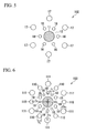
- FIG. 3 is a cross-sectional view illustrating the principal portion of an HAHF 100 of a first embodiment of the HAHF according to the present invention.
- reference numeral 11 denotes a core region
- reference numeral 12 denotes a cladding region
- reference numerals 16 denote inner holes
- reference numerals 17 denote outer holes.
- This HAHF 100 is constructed to include the core region 11, the cladding region 12 therearound, the core region 11 having a higher refractive index than that of the cladding region 12, and the holes 16 and 17 defining two layers including the inner and outer layers provided in the cladding region 12 surrounding the core region 11.
- the core region 11 is formed from a silica-based glass material, such as silica glass doped with GeO 2 for example, and the cladding region 12 is formed from a material having a lower refractive index than that of the material of the core region 11, for example, silica glass.
- the inner hole layer (first layer) includes three inner holes 16 and the outer hole layer (second layer) also includes three outer holes 17.
- the inner holes 16 and the outer holes 17 are each arranged in a circular shape.
- the three inner holes 16 have the same diameter, and the outer holes 17 also have the same diameter.
- the outer holes 17 are arranged at positions at which no inner holes 16 are arranged when viewed from the center of the core region 11.
- the relationship between distance ⁇ 1 between the center of the core region 11 and the center of the inner holes 16 and the distance ⁇ 2 between the center of the core region 11 and the center of the outer holes 17 is ⁇ 1 ⁇ ⁇ 2
- the relationship between the diameter d 1 of the inner holes and the diameter d 2 of the outer holes is d 1 ⁇ d 2 .
- These ⁇ 1 , ⁇ 2 , d 1 , and d 2 may appropriately be selected according to various parameters, such as the diameter D of the core region, the relative refractive index difference ⁇ , or the like.
- ⁇ 1 be between about 3 and about 9 ⁇ m
- ⁇ 2 be between about 5 and about 15 ⁇ m ( ⁇ 1 ⁇ ⁇ 2 )
- d 1 be between about 2 and about 8 ⁇ m
- d 2 be between about 4 and about 12 ⁇ m (d 1 ⁇ d 2 ), for example.
- the inner holes 16 are provided closer to the core region 11 without increasing the space occupancy ratio of the holes in the vicinity of the core region 11 by arranging respective holes so that the inner holes 16 have a smaller diameter while the outer holes 17 have a larger diameter, and by reducing the numbers of respective holes.
- a reduction in the cut-off wavelength ⁇ C can be achieved.
- the electromagnetic field of the fundamental mode is distributed in the same phase, light can be sufficiently contained in the core region 11 by surrounding the core region 11 with the large-diameter outer holes 17 and the small-diameter inner holes 16, thereby reducing bending loss L B .
- the cut-off wavelength ⁇ C in a higher-order mode be shorter than 1.3 ⁇ m, and bending loss L B with a bending diameter ⁇ of 10 mm at a wavelength of 1.55 ⁇ m be lower than 2.5 dB/m.
- fusion splice loss with a single-mode fiber having a step-shaped core be 0.2 dB or less at a wavelength of 1.55 ⁇ m, and mechanical splice loss be 0.5 dB or less.
- the above-described fusion splice loss is measured using the following procedures. First, a light source and a photodetector are connected together using a SMF, and an optical power P 1 that is detected is measured. Next, the SMF is cut, and a fiber to be measured in a length of several meters is fusion spliced between the two cut SMFs, and a detected optical power is measured as P 2 . In this case, loss due to the fusion splice is given by (P 1 -P 2 ) / 2.
- mechanical splice loss is similar to the above-described fusion splice loss, but is a value that is measured when fibers are mechanically spliced rather than fusion spliced.
- FIG. 4 is a cross-sectional view illustrating the principal portion of an HAHF 101 as a second embodiment of an HAHF according to the present invention.
- the HAHF 101 of this embodiment is structured to include elements similar to those of the HAHF 100 of the above-described first embodiment, and the same reference numerals are given to like elements.
- the inner hole layer and the outer hole layer are respectively composed of three holes in the HAHF 100 of the above-described first embodiment, the inner hole layer and the outer hole layer are respectively composed of four holes in the HAHF 101 of this embodiment.
- the HAHF 101 of this embodiment is capable of providing the same effects as those of the HAHF 100 of the above-described first embodiment provided that the diameter of the inner holes 16 is small.
- FIG. 5 is a cross-sectional view illustrating the principal portion of an HAHF 102 of a third embodiment of an HAHF according to the present invention.
- the HAHF 102 of this embodiment is structured to include elements similar to those of the HAHF 100 of the above-described first embodiment, and the same reference numerals are given to like elements.
- the inner hole layer and the outer hole layer are respectively composed of three holes in the HAHF 100 of the above-described first embodiment, the inner hole layer and the outer hole layer are respectively composed of six holes in the HAHF 102 of this embodiment.
- the HAHF 102 of this embodiment is capable of providing the same effects as those of the HAHF 100 of the above-described first embodiment provided that the diameter of the inner holes 16 is small.
- FIG. 6 is a cross-sectional view illustrating the principal portion of an HAHF 103 as a fourth embodiment of an HAHF according to the present invention.
- the HAHF 103 of this embodiment has the same structures of the core region I and the cladding region 12 as those of the HAHF 100 of the above-described first embodiment, but this embodiment is characterized in that four hole layers are provided around the core region 11.
- the holes of the HAHF 103 in this embodiment include a first layer composed of six first layer holes 18 provided around the core region 11; a second layer composed of six second layer holes 19 that are provided between the first layer holes 18, and are arranged such that the centers of the second layer holes 19 are located a short distance from the centers of the first layer holes 18; a third layer composed of six third layer holes 110 that are provided on an extension of a line drawn from the center of the core region 11 to the center of the first layer holes 18; and a fourth layer composed of six fourth layer holes 111 that are provided between the third layer holes 110, and are arranged such that the centers of the fourth layer holes 111 are located a short distance from the centers of the third layer holes 110.
- the distance ⁇ 1 from the center of the core region 1 to the center of a first layer hole 18, the distance ⁇ 2 from the center of the core region 11 to the center of a second layer hole 19, the distance ⁇ 3 from the center of the core region 11 to the center of a third layer hole 110, and the distance ⁇ 4 from the center of the core region 11 to the center of a fourth layer hole 111 satisfy the following relationship: ⁇ 1 ⁇ ⁇ 2 ⁇ ⁇ 3 ⁇ ⁇ 4 .
- the diameter d 1 of the first layer holes 18, the diameter d 2 of the second layer holes 19, the diameter d 3 of the third layer holes 110, and the diameter d 4 of the fourth layer holes 111 satisfy the following relationship: d 1 ⁇ d 2 ⁇ d 3 ⁇ d 4 .
- ⁇ 1 to ⁇ 4 and d 1 to d 4 may be set as appropriate according to parameters, such as the diameter D of the core region and relative refractive index difference ⁇ , and are not particularly limited. Taking a fiber having a diameter of the core region of between about 4 and about 10 ⁇ m, it is preferable that ⁇ 1 be between about 3 and 6 ⁇ m , A 2 be between about 5 and 9 ⁇ m, ⁇ 3 be between about 7 and 12 ⁇ m, and ⁇ 4 be between about 10 and 16 ⁇ m (provided that ⁇ 1 ⁇ ⁇ 2 ⁇ ⁇ 3 ⁇ ⁇ 4 ); and d 1 be between about 1 and 5 ⁇ m, d 2 be between about 2 and 6 ⁇ m, d 3 be between about 2.5 and 7 ⁇ m, and d 4 be between about 3 and 10 ⁇ m (provided that d 1 ⁇ d 2 ⁇ d 3 ⁇ d 4 ).
- the HAHF 103 of this embodiment is capable of providing the same effects as those of the HAHF 100 of the above-described first embodiment.
- the HAHF of this embodiment has a more complex structure than the HAHF of the above-described embodiments, having increased layers of holes permits more flexibility in adjusting characteristics, such as a cut-off wavelength and bending loss, thereby enabling provision of an HAHF with higher performance.
- the core region was formed from silica glass doped with GeO 2 and the cladding region was formed from sure silica.
- the diameter D of the core region was 8.5 ⁇ m, and the relative refractive index difference ⁇ as 0.34%.
- the hole diameter d 1 was 5.1 ⁇ m
- the distance ⁇ 1 from the center of the core region to the center of a hole was 8.5 ⁇ m.
- the hole diameter d 2 was 8.5 ⁇ m, and the distance ⁇ 2 from the center of the core region to the center of the hole was 11.0 ⁇ m.
- the same materials as in the HAHF of Example I were used for the core region and the cladding region.
- the diameter D of the core region was 8.5 ⁇ m, and the relative refractive index difference ⁇ was 0.34%.
- the hole diameter d 1 was 3.6 ⁇ m, and the distance ⁇ 1 from the center of the core region to the center of a hole was 7.5 ⁇ m.
- the hole diameter d 2 was 8.0 ⁇ m, and the distance ⁇ 2 from the center of the core region to the center of the hole was 13.0 ⁇ m.
- the same materials as in the HAHF of Example I were used for the core region and the cladding region.
- the diameter D of the core region was 8.5 ⁇ m, and the relative refractive index difference ⁇ was 0.34%.
- the hole diameter d 1 was 3.3 ⁇ m, and the distance ⁇ 1 from the center of the core region to the center of a hole was 6.8 ⁇ m.
- the hole diameter d 2 was 6.8 ⁇ m, and the distance ⁇ 2 from the center of the core region to the center of the hole was 14.0 ⁇ m.
- Fibers 1 and 2 had a core region with a refractive index difference with respect to pure silica ⁇ of 0.34% and a diameter D of 8.0 ⁇ m, and holes with a diameter d 1 and d 2 of 4.2 ⁇ m, a distance ⁇ 1 between the center of an inner hole and the center of the core region of 7.2 ⁇ m, and a distance ⁇ 2 between the center of an outer hole and the center of the core region of 15.0 ⁇ m.
- Fiber 1 included six inner holes and 12 outer holes, having 18 holes in total
- Fiber 2 included six inner holes and six outer holes, having 12 holes in total.
- the six outer holes of Fiber 2 were provided at regions in which inner holes are absent when viewed from the center of the core region.
- Reference numerals 112 shown in FIG. 7 denote portions in which holes of 12 outer holes are provided in Fiber 1 but omitted from Fiber 2 (omitted hole portions).
- Return loss was 45 dB at a wavelength of 1.55 ⁇ m in both cases.
- fusion splice loss was 0.11 dB in both cases and mechanical splice loss was 0.26 dB at a wavelength of 1.55 ⁇ m loss in both cases.
- Return loss was 45 dB or more in both cases.
- Fiber 2 shown in FIG. 7 was formed by omitting six outer holes of 12 outer holes, aligned with the inner holes when viewed from the center of the core region in the 18-hole type fiber 1 shown in FIG. 2 , the optical characteristics were not substantially affected.
- FIG. 8 shows a power distribution of the fundamental mode in the 18-hole type Fiber 1 shown in FIG. 2 at a wavelength of 1.55 ⁇ m
- FIG. 9 shows a power distribution of the fundamental mode in the 12-hole type Fiber shown in FIG. 7 at a wavelength of 1.55 ⁇ m.
- the spacing between the contour lines is 10 dB.
- the power distributions shown in FIG. 8 and FIG. 9 are almost the same, indicating that the outer holes omitted from Fiber 2 do not function sufficiently.
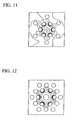
- FIG. 10 and FIG. 11 show power distributions of a higher-order mode in the 18-hole type Fiber 1 and the 12-hole type Fiber 2 at a wavelength of 1 ⁇ m, respectively.
- the spacing between the contour lines is also 10 dB.
- the principal portion of the higher-order mode is distributed in a manner similar to that of the fundamental mode, indicating that the outer holes omitted from Fiber 2 do not function sufficiently.
- Fiber 3 and 4 had a core region with a refractive index difference with respect to pure silica ⁇ of 0.34% and a diameter D of 8.5 ⁇ m, and holes with a diameter d 1 and d 2 of 4.2 ⁇ m. a distance ⁇ 1 between the center of an inner hole and the center of the core region of 9.0 ⁇ m, and a distance ⁇ 2 between the center of an outer hole and the center of the core region of 14.0 ⁇ m.
- Fiber 3 included six inner holes and 12 outer holes, having 18 holes in total
- Fiber 4 included six inner holes and six outer holes, having 12 holes in total.
- the six outer holes of Fiber 4 were provided at regions in which inner holes are absent when viewed from the center of the core region.
- Return loss was 45 dB or more at a wavelength of 1.55 ⁇ m in both cases.
- fusion splice loss was 0.10 dB and mechanical splice loss was 0.25 dB at a wavelength of 1.55 ⁇ m loss in both cases.
- Return loss was 45 dB or more in both cases.
- FIG. 12 shows a power distribution of the fundamental mode in the 18-hole type Fiber 3 at a wavelength of 1.55 ⁇ m
- FIG. 13 shows a power distribution of the fundamental mode in the 12-hole type Fiber 4 at a wavelength of 1.55 ⁇ m.
- the spacing between the contour lines is 10 dB.
- the power distributions shown in FIG. 12 and FIG. 13 are almost the same, indicating that the outer holes omitted from Fiber 4 do not function sufficiently.
- FIG. 14 and F1G. 15 show power distributions of a higher-order mode in the 18-hole type Fiber 3 and the 12-hole type Fiber 4 at a wavelength of 1 ⁇ m, respectively.
- the spacing between the contour lines is also 10 dB.
- the principal portion of the higher-order mode is distributed in a manner similar to that of the fundamental mode, indicating that the outer holes omitted from Fiber 2 do not function sufficiently.
- FIG. 16 and FIG. 17 are schematic diagrams illustrating a fifth embodiment of the low-bending loss multimode holey fiber (hereinafter abbreviated as "HF") according to the present invention.
- FIG. 16 is a graph illustrating a refractive index profile of a core region 22 of the HF
- FIG. 17 is a schematic diagram showing the structure of the HF 21.
- reference numeral 21 notes the HF
- reference numeral 22 denotes a core region
- reference numeral 23 denotes a cladding region
- reference numeral 24 denotes a first core
- reference numeral 25 denotes a second core
- reference numerals 26 denote holes.
- the HF 21 of this embodiment is made of silica-based glass, and is a holey fiber that includes a core region 22 having a higher refractive index than that of the cladding region 23 and a plurality of holes 26 around the core region 22.
- the core region 22 includes a first core 24 at the center that is made of a material having a higher refractive index than that of the cladding region 23, and a second core 25 around the first core 24, which is made of a material having a refractive index that is different from a refractive index of the first core 24 and is higher than that of the cladding region 23.
- the HF 21 of this embodiment has a structure in which six holes 26 forming a one layer are provided around the core region, as shown in FIG. 17 .
- the relative refractive index difference ⁇ 1 of the first core 24 with respect to the cladding region 23, the diameter D 1 of the first core 24, the relative refractive index difference ⁇ 2 of the second core 25 with respect to the cladding region 23, and the diameter D 2 of the second core 25 fall within the following ranges: 0.3% ⁇ ⁇ 1 ⁇ 1%, 0.1% ⁇ ⁇ 2 ⁇ 0.6%, 4 ⁇ m ⁇ D 1 ⁇ 10 ⁇ m, and 6 ⁇ m ⁇ D 2 ⁇ 15 ⁇ m.
- an HF 21 that has two or more propagation modes at wavelengths between 1.2 ⁇ m and 1.6 ⁇ m (this number of propagation modes is the number without a degenerate mode that is counted more than once), and the absolute value of a group refractive index difference ⁇ n g between the fundamental mode and the next higher-order mode of less than 1 ⁇ 10 -3 .
- fusion splicing two HFs 21 it is also possible to obtain an HF 21 that exhibits a fusion splice loss of 0.2 dB or less, mechanical splice loss of 0.4 dB or less when optical connectors are provided to ends of the HFs 21 and the connectors are made to abut each other, and return loss of 40 dB or more at a wavelength of 1.55 ⁇ m.
- the core region 22 surrounded by the holes includes the first core 24 at the center that is made of a material having a higher refractive index than that of the cladding region 23, and a second core 25 around the first core 24, which is made of a material having a refractive index that is different from a refractive index of the first core 24 and is higher than that of the cladding region 23.
- the first core 24 at the center that is made of a material having a higher refractive index than that of the cladding region 23, and a second core 25 around the first core 24, which is made of a material having a refractive index that is different from a refractive index of the first core 24 and is higher than that of the cladding region 23.
- This HF 21 has a simplified structure and exhibits very low bending loss, and can be connected with a conventional SMF with very low splice loss. Thus, it can be applied to house wiring in which flexibility of wiring and ease of installation are required, thereby improving the performance of optical communication.
- the arrangement of the holes of the HF of the present invention is not limited to six holes in one layer according to the above-described fifth embodiment, and other arrangements may be employed. However, it is preferable that the number of layers of the holes surrounding the core region 22 be two or less, the holes in each layer be arranged evenly spaced, and the number of holes in each layer be between 3 and 8. Hereinafter, other arrangements of the holes will be illustrated in second to fourth embodiments.
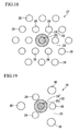
- FIG. 18 is a diagram illustrating a sixth embodiment of the HF according to the present invention.
- the HF 7 of this embodiment is constructed to have the same elements as those of the HF 21 of the above-described fifth embodiment, and to further include twelve holes 26 that define a second layer around the six holes 26 that define the first layer, coming to eighteen holes 26 in the two layers in total.
- the HF 7 of this embodiment is capable of providing the same effects as those of the HF 21 of the above-described fifth embodiment.
- FIG. 19 is a diagram illustrating a seventh embodiment of the HF according to the present invention.
- An HF 28 of this embodiment is characterized in that it includes a core region 22 having the first core 24, the second core 25 provided therearound, similar to in the HF 21 of the above-described fifth embodiment, and the two layers of the inner and outer layers of holes 29 and 30 surrounding the core region 22, and that the hole diameter of the inner holes 29 is different from the hole diameter of the outer holes 210.
- the HF 28 of this embodiment is capable of providing the same effects as those of the HF 21 of the above-described fifth embodiment.
- FIG. 22 is a diagram illustrating a seventh embodiment of the HF according to the present invention.
- the HF 28 of this embodiment includes a core region 22 having the first core 24, the second core 25 provided therearound, similar to in the HF 21 of the above-described fifth embodiment, and three holes 26 surrounding the core region 22 (three holes in one layer).
- the HF 31 of this embodiment is capable of providing the same effects as those of the HF 21 of the above-described fifth embodiment.
- the measurement results of equivalent group refractive indices in the fundamental mode and a higher-order mode of this HF 21 are shown in FIG. 20 .
- ) between the two modes was 2 ⁇ 10 -4 or lower at wavelengths between 1.2 and 1.6 ⁇ m, wherein n gf and n gh , represent group refractive indices of the fundamental mode and the higher-order mode, respectively.
- degradation of signals due to modal dispersion is 0.7 ns/km or less. Since a fiber is used after being connected with an SMF in actual application, higher-order modes are not substantially pumped at all. Therefore, the actual degradation of signals due to modal dispersion was 0.1 ns/km or less.
- the test-fabricated HF 21 exhibited bending loss of 0.02 dB/m with a bending diameter ⁇ of 10 mm at a wavelength of 1.55 ⁇ m. Furthermore, in HF 21, when the holes 26 were collapsed upon fusion splicing, it could be connected with an SMF with very low loss since it has a mode field diameter (MFD) of about 10 ⁇ m at a wavelength of 1.55 ⁇ m, which is a comparable level to that of a conventional SMF.
- MFD mode field diameter
- Splice loss was low at a wavelength of 1.55 ⁇ m when the HF 21 and an SMF were actually connected, with fusion splice loss of about 0.1 dB and mechanical splice loss of about 0.2 dB when optical connectors were provided to ends of the fibers and the connectors were made to abut each other to connect them.
- the measurement results of equivalent group refractive indices in the fundamental mode and a higher-order mode of this HF 21 are shown in FIG. 21 .
- the group refractive index difference ⁇ n g between the two modes was 3 ⁇ 10 -4 or lower at wavelengths between 1.2 and 1.6 ⁇ m. Actual degradation of signals due to modal dispersion was 0.1 ns/km or less.
- the test-fabricated HF 21 exhibited bending loss of 0.02 dB/m with a bending diameter ⁇ of 10 mm at a wavelength of 1.55 ⁇ m. Furthermore, splice loss was low at a wavelength of 1.55 ⁇ m, with fusion splice loss of about 0.2 dB and mechanical splice loss of about 0.3 dB when optical connectors were provided to ends of the fibers and the connectors were made to abut each other to connect them.
- the measurement results of equivalent group refractive indices in the fundamental mode and a higher-order mode of this HF 31 are shown in FIG. 23 .
- the group refractive index difference ⁇ n g between the two modes was 1 ⁇ 10 -4 or lower at wavelengths between 1.2 and 1.6 ⁇ m.
- the test-fabricated HF 31 exhibited bending loss of 0.03 dB/m with a bending diameter ⁇ of 10 mm at a wavelength of 1.55 ⁇ m. Furthermore, splice loss was low at a wavelength of 1.55 ⁇ m, with fusion splice loss of about 0.1 dB and mechanical splice loss of about 0.2 dB when optical connectors were provided to ends of the fibers and the connectors were made to abut each other to connect them.
Landscapes
- Physics & Mathematics (AREA)
- General Physics & Mathematics (AREA)
- Optics & Photonics (AREA)
- Optical Fibers, Optical Fiber Cores, And Optical Fiber Bundles (AREA)
- Manufacture, Treatment Of Glass Fibers (AREA)
Abstract
The core region (22) comprises a first core (24) at a center and a second core (25) around the first core (24) which are made of materials having two different respective indexes higher than that of a material of the cladding region.
Description
- The present invention relates to a hole-assisted holey fiber having holes disposed around a core region. The hole-assisted holey fiber of the present invention is employed in the field of optical communications or the like, and exhibits low bending loss, making it more suitable for a user's on-site wiring than conventional single-mode optical fibers.
- Furthermore, the present invention is relates to a low-bending loss multimode holey fiber that exhibits low bending loss characteristics even with a very small bending radius.
- Priority is claimed on Japanese Patent Application No.
2004-205819, filed July 13, 2004 2004-279453, filed September 27, 2004 - House wiring optical fibers used for the FTTH (fiber to the home) technique desirably have excellent bending loss characteristics when flexibility of laying cables and ease of installation are taken into consideration. Although improvement in bending loss characteristics can be achieved by increasing a relative refractive index difference between the core and cladding, an increased relative refractive index difference increases containment of higher-order modes, thereby making cut-off wavelengths in higher-order modes longer.
- A hole-assisted holey fiber (HA-HF) has been proposed as a significantly low-loss fiber compared to typical single-mode fibers (hereinafter abbreviated as "SMFs") used in an optical transmission path. A holey fiber is constructed such that a plurality of holes are disposed around its core, and it exhibits a larger relative refractive index difference between the core and the cladding and a lower bending loss characteristic even with small-diameter bending, as compared to conventional SMFs.
- However, even through conventional holey fibers can achieve low bending loss, they cannot completely eliminate the tradeoff of a lower bending loss versus a longer cut-off wavelength (see T. Hasegawa, et al, "Novel hole-assisted lightguide fiber exhibiting large anomalous dispersion and low loss below 1dB/km", Proc. OFC, PD5, 2001).
- The following types of hole-assisted holey fibers (hereinafter referred to as HAHFs) have been proposed: one in which a plurality of holes are disposed around the core to form one layer of holes, as shown in
FIG. 1 (see B. Yao, et al., "Low-loss holey fiber," Proc. 53rd IWCS, pp.135-139, 2004, for example); and another in which a plurality of holes are disposed around the core to form two layers of holes, as shown inFIG. 2 (see T. Hasegawa, et al., "Bending-insensitive single-mode holey fibre with SMF-compatibility for optical wiring applications," ECOC-IOOC 2003 Proc., We2.7.3, 2003, for example). - The type of HAHF shown in
FIG. 1 in which holes are arranged to form one layer includes acore 11, acladding region 12 therearound, the core region having a higher refractive index than that of thecladding region 12, and a plurality (six in the example shown in the figure) ofholes 13 provided in thecladding region 12 along a circle concentric around thecore region 11. Each of the plurality ofholes 13 has the same diameter, and the distances between the center of the core region and the centers of each of theholes 13 are all equal. - The type of HAHF shown in
FIG. 2 in which holes are arranged to form two layers includes acore 11, acladding region 12 therearound, the core region having a higher refractive index than that of thecladding region 12, sixinner holes 14 provided in thecladding region 12 along a circle concentric around thecore region 11, and twelve outer holes 15 provided outside from theinner holes 14. In the illustrated example, theinner holes 14 and the outer holes 15 are all formed to have the same diameter. Furthermore, in this HAHF, one-half of the outer holes 15 are arranged on lines extended from the center of the core region through theinner holes 14. - Among the above-described conventional HAHFs, although the HAHF shown in
FIG. 1 has a simpler structure than the HAHF shown inFIG. 2 , obtaining a fiber with a low bending loss LB and a short cut-off wavelength λC is limited by a trade-off. More specifically, in order to reduce the bending loss LB, the diameter of the holes should be enlarged so that the ratio of the space occupied by the holes in the cladding region is increased. On the other hand, in order to reduce the cut-off wavelength λC, containment of higher-order modes should be minimized. For this purpose, the space occupancy ratio should be reduced or the holes should be disposed closer to the core region. However, in the structure as shown inFIG. 1 , since disposing the holes closer to the core region results in an increased space occupancy ratio, it becomes difficult to achieve both a low bending loss LB and a short cut-off wavelength λC. - Furthermore, since the HAHF shown in
FIG. 2 has the second layer of the holes outside from the holes in the fiber shown inFIG. 1 , it permits more flexibility in adjusting the bending loss and the cut-off wavelength than the HAHF shown inFIG. 1 . However, a large number of holes, i.e., 18, and a relatively complex structure of this fiber may cause increased production cost. - The present invention was conceived in view of the above-mentioned background, and it is directed to provide a high-performance HAHF that realizes both a low bending loss LB and shorter cut-off wavelength λC.
- Furthermore, the present invention is also directed to a low-bending loss multimode holey fiber that is suitable as an optical fiber for house wiring that is associated with bending with low curvature.
- In order to achieve the above-mentioned object, the present invention provides a hole-assisted holey fiber, comprising: a core region; a cladding region provided around the core region; and a plurality of holes that are provided in the cladding region around the core region, wherein a refractive index of the core region is higher than that of the cladding region, the holes form two layers comprising an inner hole layer and an outer hole layer, the inner hole layer has the same number of holes as the number of the holes in the outer hole layer, the outer holes are provided in locations in which holes are absent when viewed from the center of the core region, holes defining the same layer have the same diameter, a distance Λ1 from a center of the core region to a center of an inner hole and a distance Λ2 from the center of the core region to a center of an outer hole satisfy Λ1 < Λ2, and a diameter d1 of an inner hole and a diameter d2 of an outer hole satisfy d1 ≤ d2.
- In the HAHF according to the present invention, it is preferable that the numbers of holes in the inner hole layer and the outer hole layer each range between 3 and 8.
- In the HAHF according to the present invention, it is preferable that a cut-off wavelength λC in a higher-order mode be shorter than 1.3 µm, and a bending loss LB with a bending diameter ϕ of 10 mm at a wavelength of 1.55 µm be lower than 2.5 dB/m.
- In the HAHF according to the present invention, it is preferable that a fusion splice loss be 0.2 dB or less and a mechanical splice loss be 0.5 dB or less with a SMF having a step-shaped core at a wavelength of 1.55 µm.
- Furthermore, it is preferable that the core region of the HAHF have the same structural parameters as those of a core of the SMF.
- Furthermore, the present invention provides a hole-assisted holey fiber, comprising: a core region; a cladding region provided around the core region; and a plurality of holes that are provided in the cladding region around the core region, wherein a refractive index of the core region is higher than that of the cladding region, the holes define two or more layers comprising an inner hole layer and an outer hole layer, a distance Ai from a center of the core region to a center of an inner hole and a distance Λj from the center of the core region to a center of an outer hole satisfy Λi < Λj, and a diameter di of an inner hole and a diameter dj of an outer hole satisfy di ≤ dj (where "i" and "j" are ascending numeric orders of the hole layers counted from the center, and i < j), the outer holes are provided in locations in which holes are absent when viewed from the center of the core region, and holes defining the same layer have the same diameter.
- In the HAHF according to the present invention, it is preferable that the numbers of holes in the respective hole layers range between 3 and 8.
- In the HAHF according to the present invention, it is preferable that a cut-off wavelength λC in a higher-order mode be shorter than 1.3 µm, and a bending loss LB with a bending diameter ϕ of 10 mm at a wavelength of 1.55 µm be lower than 2.5 dB/m.
- In the HAHF according to the present invention, it is preferable that a fusion splice loss be 0.2 dB or less and a mechanical splice loss be 0.5 dB or less with a SMF having a step-shaped core at a wavelength of 1.55 µm.
- Furthermore, it is preferable that the core region of the HAHF have the same structural parameters as those of a core of the SMF.
- In order to achieve the above-mentioned objects, the present invention provides a holey fiber comprising: a core region; a cladding region; and a plurality of holes surrounding the core region, wherein the core region has a higher refractive index than that of the cladding region, the core region comprises a first core at a center that is made of a material having a higher refractive index than that of the cladding region, and a second core around the first core, which is made of a material having a refractive index that is different from a refractive index of the first core and higher than that of a material of the cladding region.
- In the low-bending loss multimode holey fiber according to the present invention, it is preferable that a relative refractive index difference Δ1, of the first core with respect to the cladding region, a diameter D1 of the first core, a relative refractive index difference Δ2 of the second core with respect to the cladding region, and a diameter D2 of the second core fall within the following ranges: 0.3%≤ Δ1 ≤ 1%, 0.1 % ≤ Δ2 < 0.6%, 4 µm ≤ D1 ≤ 10 µm, and 6 µm ≤ D2 ≤ 15 µm.
- In the low-bending loss multimode holey fiber according to the present invention, it is preferable that the low-bending loss multimode holey fiber have two or more propagation modes at wavelengths between 1.2 µm and 1.6 µm (the number of propagation modes is the number without a degenerate mode that is counted more than once), wherein an absolute value of a group refractive index difference Δng between a fundamental mode and a next higher-order mode be less than 1 × 10⁻³.
- In the low-bending loss multimode holey fiber according to the present invention, it is preferable that a modal dispersion due to multimode propagation be 0.5 ns/km or less when the low-bending loss multimode holey fiber is spliced with an SMF having a step-shaped refractive index profile.
- In the low-bending loss multimode holey fiber according to the present invention, it is preferable that a bending loss be 0.1 dB/m or less with a bending diameter ϕ of 10 mm at a wavelength of 1.55 µm.
- In the low-bending loss multimode holey fiber according to the present invention, it is preferable that a fusion splice loss and a mechanical splice loss with a single-mode fiber having a step-shaped core be 0.2 dB or less and 0.4 dB or less, respectively, and a return loss be 40 dB or more at a wavelength of 1.55 µm when the low-bending loss multimode holey fiber is spliced with a single-mode fiber having a step-shaped core.
- In the low-bending loss multimode holey fiber according to the present invention, it is preferable that a fusion splice loss and a mechanical splice loss with a single-mode fiber having a step-shaped core be 0.2 dB or less and 0.4 dB or less, respectively, and a return loss be 40 dB or more at a wavelength of 1.55 µm when the low-bending loss multimode holey fiber is spliced with a same fiber.
- In the low-bending loss multimode holey fiber according to the present invention, it is preferable that the holes surrounding the core region define two layers, the holes in each layer be arranged evenly spaced, and the number of holes in each layer be between 3 and 8.
- In the low-bending loss multimode holey fiber according to the present invention, it is preferable that the holes surrounding the core region define two layers, and a diameter of the holes be different from layer to layer.
- With the HAHF according to the present invention, a single-mode fiber is obtained which exhibits a short cut-off wavelength λC and low bending loss LB with a simplified structure.
- In addition to exhibiting a short cut-off wavelength λC and low bending loss LB, the HAHF according to the present invention can be fusion spliced or mechanically spliced with an SMF with low splice loss. Thereby, it can be applied to long-haul transmission, as well as user's on-site wiring.
- In the low-bending loss multimode holey fiber according to the present invention, the core region surrounded by holes includes a first core at the center that is made of a material having a higher refractive index than that of the cladding region, and a second core around the first core, which is made of a material having a refractive index that is different from a refractive index of the first core and higher than that of a material of the cladding region. Thus, it exhibits extremely low bending loss even with a very small bending radius.
- The low-bending loss multimode holey fiber according to the present invention has a simplified structure and exhibits very low bending loss, and can be connected with a conventional SMF with very low splice loss. Thus, it can be applied to house wiring in which flexibility of wiring and ease of installation are required, thereby improving the performance of optical communication.
-
-
FIG. 1 is a cross-sectional view illustrating the principal portion of an HAHF as an example of a conventional HAHF. -
FIG. 2 is a cross-sectional view illustrating the principal portion of an HAHF as another example of a conventional HAHF. -
FIG. 3 is a cross-sectional view illustrating the principal portion of an HAHF as a first embodiment of the HAHF according to the present invention. -
FIG. 4 is a cross-sectional view illustrating the principal portion of an HAHF as a second embodiment of the HAHF according to the present invention. -
FIG. 5 is a cross-sectional view illustrating the principal portion of an HAHF as a third embodiment of the HAHF according to the present invention. -
FIG. 6 is a cross-sectional view illustrating the principal portion of an HAHF as a fourth embodiment of the HAHF according to the present invention. -
FIG. 7 is a cross-sectional view illustrating the principal portion of an HAHF made as an example according to the present invention. -
FIG. 8 is a graph showing power distribution of the fundamental mode of a conventional 18-hole type fiber at a wavelength of 1.55 µm. -
FIG. 9 is a graph showing a power distribution of the fundamental mode of a 12-hole type fiber according to the present invention at a wavelength of 1.55 µm. -
FIG. 10 is a graph showing the power distribution of a higher-order mode of a conventional 18-hole type fiber at a wavelength of 1 µm. -
FIG. 11 is a graph showing the power distribution of a higher-order mode of a 12-hole type fiber according to the present invention at a wavelength of 1 µm. -
FIG. 12 is a graph showing a power distribution of the fundamental mode of a conventional 18-hole type fiber at a wavelength of 1.55 µm. -
FIG. 13 is a graph showing a power distribution of the fundamental mode of a 12-hole type fiber according to the present invention at a wavelength of 1.55 µm. -
FIG. 14 is a graph showing the power distribution of a higher-order mode of a conventional 18-hole type fiber at a wavelength of 1 µm. -
FIG. 15 is a graph showing the power distribution of a higher-order mode of a 12-hole type fiber according to the present invention at a wavelength of 1 µm. -
FIG. 16 is a graph showing the refractive index profile at a core region of a low-bending loss multimode holey fiber according to the present invention. -
FIG. 17 is a schematic diagram illustrating a fifth embodiment of the low-bending loss multimode holey fiber according to the present invention. -
FIG. 18 is a schematic diagram illustrating a sixth embodiment of the low-bending loss multimode holey fiber according to the present invention. -
FIG. 19 is a schematic diagram illustrating a seventh embodiment of the low-bending loss multimode holey fiber according to the present invention. -
FIG. 20 is a graph showing results of Example 6 according to the present invention. -
FIG. 21 is a graph showing results of Example 7 according to the present invention. -
FIG. 22 is a schematic diagram illustrating an eighth embodiment of the low-bending loss multimode holey fiber according to the present invention. -
FIG. 23 is a graph showing results of Example 8 according to the present invention. - Hereinafter, various embodiments of the present invention will be described with reference to the drawings.
-
FIG. 3 is a cross-sectional view illustrating the principal portion of anHAHF 100 of a first embodiment of the HAHF according to the present invention. In this figure,reference numeral 11 denotes a core region,reference numeral 12 denotes a cladding region,reference numerals 16 denote inner holes, andreference numerals 17 denote outer holes. - This
HAHF 100 is constructed to include thecore region 11, thecladding region 12 therearound, thecore region 11 having a higher refractive index than that of thecladding region 12, and theholes cladding region 12 surrounding thecore region 11. Thecore region 11 is formed from a silica-based glass material, such as silica glass doped with GeO2 for example, and thecladding region 12 is formed from a material having a lower refractive index than that of the material of thecore region 11, for example, silica glass. - The inner hole layer (first layer) includes three
inner holes 16 and the outer hole layer (second layer) also includes threeouter holes 17. Theinner holes 16 and theouter holes 17 are each arranged in a circular shape. The threeinner holes 16 have the same diameter, and theouter holes 17 also have the same diameter. Theouter holes 17 are arranged at positions at which noinner holes 16 are arranged when viewed from the center of thecore region 11. - The relationship between distance Λ1 between the center of the
core region 11 and the center of theinner holes 16 and the distance Λ2 between the center of thecore region 11 and the center of theouter holes 17 is Λ1 < Λ2, and the relationship between the diameter d1 of the inner holes and the diameter d2 of the outer holes is d1 < d2. These Λ1, Λ2, d1, and d2 may appropriately be selected according to various parameters, such as the diameter D of the core region, the relative refractive index difference Δ, or the like. Although it is not a limitation, if a fiber having the diameter of the core region of between about 4 and about 10 µm is used, it is preferable that Λ1 be between about 3 and about 9 µm, Λ2 be between about 5 and about 15 µm (Λ1 ≤ Λ2), d1 be between about 2 and about 8 µm, and d2 be between about 4 and about 12 µm (d1≤d2), for example. - In this
HAHF 100, theinner holes 16 are provided closer to thecore region 11 without increasing the space occupancy ratio of the holes in the vicinity of thecore region 11 by arranging respective holes so that theinner holes 16 have a smaller diameter while theouter holes 17 have a larger diameter, and by reducing the numbers of respective holes. As a result, since it is possible to reduce the equivalent refractive index of higher-order modes without containing the higher-order modes, a reduction in the cut-off wavelength λC can be achieved. On the other hand, since the electromagnetic field of the fundamental mode is distributed in the same phase, light can be sufficiently contained in thecore region 11 by surrounding thecore region 11 with the large-diameterouter holes 17 and the small-diameterinner holes 16, thereby reducing bending loss LB. - In the
HAHF 100, it is preferable that the cut-off wavelength λC in a higher-order mode be shorter than 1.3 µm, and bending loss LB with a bending diameter ϕ of 10 mm at a wavelength of 1.55 µm be lower than 2.5 dB/m. - Furthermore, in this HAHF, it is preferable that fusion splice loss with a single-mode fiber having a step-shaped core be 0.2 dB or less at a wavelength of 1.55 µm, and mechanical splice loss be 0.5 dB or less.
- The above-described fusion splice loss is measured using the following procedures. First, a light source and a photodetector are connected together using a SMF, and an optical power P1 that is detected is measured. Next, the SMF is cut, and a fiber to be measured in a length of several meters is fusion spliced between the two cut SMFs, and a detected optical power is measured as P2. In this case, loss due to the fusion splice is given by (P1-P2) / 2.
- Furthermore, mechanical splice loss is similar to the above-described fusion splice loss, but is a value that is measured when fibers are mechanically spliced rather than fusion spliced.
-
FIG. 4 is a cross-sectional view illustrating the principal portion of anHAHF 101 as a second embodiment of an HAHF according to the present invention. TheHAHF 101 of this embodiment is structured to include elements similar to those of theHAHF 100 of the above-described first embodiment, and the same reference numerals are given to like elements. - While the inner hole layer and the outer hole layer are respectively composed of three holes in the
HAHF 100 of the above-described first embodiment, the inner hole layer and the outer hole layer are respectively composed of four holes in theHAHF 101 of this embodiment. - The
HAHF 101 of this embodiment is capable of providing the same effects as those of theHAHF 100 of the above-described first embodiment provided that the diameter of theinner holes 16 is small. -
FIG. 5 is a cross-sectional view illustrating the principal portion of anHAHF 102 of a third embodiment of an HAHF according to the present invention. TheHAHF 102 of this embodiment is structured to include elements similar to those of theHAHF 100 of the above-described first embodiment, and the same reference numerals are given to like elements. - While the inner hole layer and the outer hole layer are respectively composed of three holes in the
HAHF 100 of the above-described first embodiment, the inner hole layer and the outer hole layer are respectively composed of six holes in theHAHF 102 of this embodiment. - The
HAHF 102 of this embodiment is capable of providing the same effects as those of theHAHF 100 of the above-described first embodiment provided that the diameter of theinner holes 16 is small. -
FIG. 6 is a cross-sectional view illustrating the principal portion of anHAHF 103 as a fourth embodiment of an HAHF according to the present invention. TheHAHF 103 of this embodiment has the same structures of the core region I and thecladding region 12 as those of theHAHF 100 of the above-described first embodiment, but this embodiment is characterized in that four hole layers are provided around thecore region 11. - The holes of the
HAHF 103 in this embodiment include a first layer composed of six first layer holes 18 provided around thecore region 11; a second layer composed of six second layer holes 19 that are provided between the first layer holes 18, and are arranged such that the centers of the second layer holes 19 are located a short distance from the centers of the first layer holes 18; a third layer composed of six third layer holes 110 that are provided on an extension of a line drawn from the center of thecore region 11 to the center of the first layer holes 18; and a fourth layer composed of six fourth layer holes 111 that are provided between the third layer holes 110, and are arranged such that the centers of the fourth layer holes 111 are located a short distance from the centers of the third layer holes 110. - The distance Λ1 from the center of the
core region 1 to the center of afirst layer hole 18, the distance Λ2 from the center of thecore region 11 to the center of asecond layer hole 19, the distance Λ3 from the center of thecore region 11 to the center of athird layer hole 110, and the distance Λ4 from the center of thecore region 11 to the center of afourth layer hole 111 satisfy the following relationship: Λ1 < Λ2 < Λ3 < Λ4. Furthermore, the diameter d1 of the first layer holes 18, the diameter d2 of the second layer holes 19, the diameter d3 of the third layer holes 110, and the diameter d4 of the fourth layer holes 111 satisfy the following relationship: d1 < d2 < d3 < d4. - These Λ1 to Λ4 and d1 to d4 may be set as appropriate according to parameters, such as the diameter D of the core region and relative refractive index difference Δ, and are not particularly limited. Taking a fiber having a diameter of the core region of between about 4 and about 10 µm, it is preferable that Λ1 be between about 3 and 6 µm, A2 be between about 5 and 9 µm, Λ3 be between about 7 and 12 µm, and Λ4 be between about 10 and 16 µm (provided that Λ1 < Λ2 < Λ3 < Λ4); and d1 be between about 1 and 5 µm, d2 be between about 2 and 6 µm, d3 be between about 2.5 and 7 µm, and d4 be between about 3 and 10 µm (provided that d1 ≤ d2 ≤ d3 ≤ d4).
- The
HAHF 103 of this embodiment is capable of providing the same effects as those of theHAHF 100 of the above-described first embodiment. Although the HAHF of this embodiment has a more complex structure than the HAHF of the above-described embodiments, having increased layers of holes permits more flexibility in adjusting characteristics, such as a cut-off wavelength and bending loss, thereby enabling provision of an HAHF with higher performance. - An HAHF having holes that formed two layers, i.e., the inner and outer layers, around the core region, in which the respective numbers of holes in the inner and outer layers were three, as shown in
FIG. 3 , was fabricated. The core region was formed from silica glass doped with GeO2 and the cladding region was formed from sure silica. The diameter D of the core region was 8.5 µm, and the relative refractive index difference Δ as 0.34%. For the inner hole layer, the hole diameter d1 was 5.1 µm, and the distance Λ1 from the center of the core region to the center of a hole was 8.5 µm. For the outer hole layer, the hole diameter d2 was 8.5 µm, and the distance Λ2 from the center of the core region to the center of the hole was 11.0 µm. - The characteristics of the fiber were as follows: a cut-off wavelength λC of 1.24 µm and bending loss LB with a bending diameter ϕ of 10 mm at a wavelength of 1.55 µm of 1.97 dB/m. Furthermore, fusion splice loss with an SMF having a similar core (D = 8.5 µm and Δ = 0.34%) was 0.05 db at a wavelength of 1.55 µm, and corresponding mechanical splice loss was 0.30 dB.
- An HAHF having holes that formed two layers, i.e., the inner and outer layers, around the core region, in which the respective numbers of holes in the inner and outer layers were four, as shown in
FIG. 4 , was fabricated. The same materials as in the HAHF of Example I were used for the core region and the cladding region. The diameter D of the core region was 8.5 µm, and the relative refractive index difference Δ was 0.34%. For the inner hole layer, the hole diameter d1 was 3.6 µm, and the distance Λ1 from the center of the core region to the center of a hole was 7.5 µm. For the outer hole layer, the hole diameter d2 was 8.0 µm, and the distance Λ2 from the center of the core region to the center of the hole was 13.0 µm. - The characteristics of the fiber were as follows: a cut-off wavelength λC of 1.28 µm and bending loss LB with a bending diameter ϕ of 10 mm at a wavelength of 1.55 µm of 2.05 dB/m. Furthermore, fusion splice loss with an SMF having a similar core (D = 8.5 µm and Δ = 0.34%) was 0.20 db at a wavelength of 1.55 µm, and corresponding mechanical splice loss was 0.32 dB.
- An HAHF having holes that formed two layers, i.e., the inner and outer layers, around the core region, in which the respective numbers of holes in the inner and outer layers were six, as shown in
FIG. 5 , was fabricated. The same materials as in the HAHF of Example I were used for the core region and the cladding region. The diameter D of the core region was 8.5 µm, and the relative refractive index difference Δ was 0.34%. For the inner hole layer, the hole diameter d1 was 3.3 µm, and the distance Λ1 from the center of the core region to the center of a hole was 6.8 µm. For the outer hole layer, the hole diameter d2 was 6.8 µm, and the distance Λ2 from the center of the core region to the center of the hole was 14.0 µm. - The characteristics of the fiber were as follows: a cut-off wavelength λC of 1.29 µm and bending loss LB with a bending diameter ϕ of 10 mm at a wavelength of 1.55 µm of 1.70 dB/m. Furthermore, fusion splice loss with an SMF having a similar core (D = 8.5 µm and Δ = 0.34%) was 0.19 db at a wavelength of 1.55 µm, and corresponding mechanical splice loss was 0.27 dB.
- A fiber having the structure shown in
FIG. 2 (Fiber 1) and another fiber having the structure shown inFIG. 7 (Fiber 2) were fabricated, which were similar except for the number of holes. BothFibers Fiber 1 included six inner holes and 12 outer holes, having 18 holes in total, whereasFiber 2 included six inner holes and six outer holes, having 12 holes in total. As shown inFIG. 7 , the six outer holes ofFiber 2 were provided at regions in which inner holes are absent when viewed from the center of the core region.Reference numerals 112 shown inFIG. 7 denote portions in which holes of 12 outer holes are provided inFiber 1 but omitted from Fiber 2 (omitted hole portions). - Higher-order mode cut-off wavelengths were 1.21 µm for
Fiber 1 and 1.19 µm forFiber 2, and bending loss with a bending diameter ϕ of 10 mm at a wavelength of 1.55 µm was 2.0 dB/m forFiber 1 and 2.2 dB/m forFiber 2. The two fibers exhibited almost substantially similar optical characteristics. - Furthermore, fusion splice loss with an SMF having a conventional step-shaped core (D = 8.5 µm and Δ = 0.34%) was 0.08 dB in both cases, and mechanical splice loss with the same fiber was 0.22 dB at a wavelength of 1.55 µm in both cases. Return loss was 45 dB at a wavelength of 1.55 µm in both cases.
- Furthermore, when two HAHFs were spliced, fusion splice loss was 0.11 dB in both cases and mechanical splice loss was 0.26 dB at a wavelength of 1.55 µm loss in both cases. Return loss was 45 dB or more in both cases.
- That is, when
Fiber 2 shown inFIG. 7 was formed by omitting six outer holes of 12 outer holes, aligned with the inner holes when viewed from the center of the core region in the 18-hole type fiber 1 shown inFIG. 2 , the optical characteristics were not substantially affected. - This can be verified through theoretical calculations.
FIG. 8 shows a power distribution of the fundamental mode in the 18-hole type Fiber 1 shown inFIG. 2 at a wavelength of 1.55 µm, andFIG. 9 shows a power distribution of the fundamental mode in the 12-hole type Fiber shown inFIG. 7 at a wavelength of 1.55 µm. In theseFIGS. 8 and9 , the spacing between the contour lines is 10 dB. The power distributions shown inFIG. 8 andFIG. 9 are almost the same, indicating that the outer holes omitted fromFiber 2 do not function sufficiently. - Similarly,
FIG. 10 andFIG. 11 show power distributions of a higher-order mode in the 18-hole type Fiber 1 and the 12-hole type Fiber 2 at a wavelength of 1 µm, respectively. In theseFIGS. 10 and11 , the spacing between the contour lines is also 10 dB. As shown in these figures, the principal portion of the higher-order mode is distributed in a manner similar to that of the fundamental mode, indicating that the outer holes omitted fromFiber 2 do not function sufficiently. - A fiber having the structure shown in
FIG. 2 (Fiber 3) and another fiber having the structure shown inFIG. 7 (Fiber 4) were fabricated, which were similar except for the number of holes. BothFibers Fiber 3 included six inner holes and 12 outer holes, having 18 holes in total, whereasFiber 4 included six inner holes and six outer holes, having 12 holes in total. As shown inFIG. 7 , the six outer holes ofFiber 4 were provided at regions in which inner holes are absent when viewed from the center of the core region. - Higher-order mode cut-off wavelengths were 1.28 µm for
Fiber 3 and 1.26 µm forFiber 4, and bending loss with a bending diameter ϕ of 10 mm at a wavelength of 1.55 µm was 1.5 dB/m forFiber 3 and 1.7 dB/m forFiber 4. The two fibers exhibited almost substantially similar optical characteristics. - Furthermore, fusion splice loss with an SMF having a conventional step-shaped core (D = 8.5 µm and Δ = 0.34%) was 0.05 dB in both cases, and mechanical splice loss with the same fiber was 0.20 dB at a wavelength of 1.55 µm in both cases. Return loss was 45 dB or more at a wavelength of 1.55 µm in both cases.
- Furthermore, when two HAHFs were spliced, fusion splice loss was 0.10 dB and mechanical splice loss was 0.25 dB at a wavelength of 1.55 µm loss in both cases. Return loss was 45 dB or more in both cases.
-
FIG. 12 shows a power distribution of the fundamental mode in the 18-hole type Fiber 3 at a wavelength of 1.55 µm, andFIG. 13 shows a power distribution of the fundamental mode in the 12-hole type Fiber 4 at a wavelength of 1.55 µm. In theseFIGS. 12 and13 , the spacing between the contour lines is 10 dB. The power distributions shown inFIG. 12 andFIG. 13 are almost the same, indicating that the outer holes omitted fromFiber 4 do not function sufficiently. - Similarly,
FIG. 14 and F1G. 15 show power distributions of a higher-order mode in the 18-hole type Fiber 3 and the 12-hole type Fiber 4 at a wavelength of 1 µm, respectively. In theseFIGS. 14 and15 , the spacing between the contour lines is also 10 dB. As shown in these figures, the principal portion of the higher-order mode is distributed in a manner similar to that of the fundamental mode, indicating that the outer holes omitted fromFiber 2 do not function sufficiently. -
FIG. 16 and FIG. 17 are schematic diagrams illustrating a fifth embodiment of the low-bending loss multimode holey fiber (hereinafter abbreviated as "HF") according to the present invention.FIG. 16 is a graph illustrating a refractive index profile of acore region 22 of the HF, andFIG. 17 is a schematic diagram showing the structure of theHF 21. In these figures,reference numeral 21 notes the HF,reference numeral 22 denotes a core region,reference numeral 23 denotes a cladding region,reference numeral 24 denotes a first core,reference numeral 25 denotes a second core, andreference numerals 26 denote holes. - The
HF 21 of this embodiment is made of silica-based glass, and is a holey fiber that includes acore region 22 having a higher refractive index than that of thecladding region 23 and a plurality ofholes 26 around thecore region 22. Thecore region 22 includes afirst core 24 at the center that is made of a material having a higher refractive index than that of thecladding region 23, and asecond core 25 around thefirst core 24, which is made of a material having a refractive index that is different from a refractive index of thefirst core 24 and is higher than that of thecladding region 23. TheHF 21 of this embodiment has a structure in which sixholes 26 forming a one layer are provided around the core region, as shown inFIG. 17 . - In the
HF 21, it is preferable that the relative refractive index difference Δ1 of thefirst core 24 with respect to thecladding region 23, the diameter D1 of thefirst core 24, the relative refractive index difference Δ2 of thesecond core 25 with respect to thecladding region 23, and the diameter D2 of thesecond core 25 fall within the following ranges: 0.3% ≤ Δ1 ≤ 1%, 0.1% ≤ Δ2 ≤ 0.6%, 4 µm ≤ D1 ≤ 10 µm, and 6 µm ≤ D2 ≤ 15 µm. - When the above-described Δ1, Δ2, D1, and D2 are in the above-described ranges, it is possible to obtain an
HF 21 that has bending loss of 0.1 dB/m or less with a bending diameter ϕ of 10 mm at a wavelength of 1.55 µm. - Furthermore, it is also possible to obtain an
HF 21 that has two or more propagation modes at wavelengths between 1.2 µm and 1.6 µm (this number of propagation modes is the number without a degenerate mode that is counted more than once), and the absolute value of a group refractive index difference Δng between the fundamental mode and the next higher-order mode of less than 1 × 10⁻³. - Furthermore, it is possible to obtain an
HF 21 that exhibits modal dispersion due to multimode propagation of 0.5 ns/km or less when theHF 21 is spliced with an SMF having a step-shaped refractive index profile. - When splicing in this manner, it is also possible to obtain an
HF 21 that exhibits fusion splice loss between theHF 21 and the SMF of 0.2 dB or less, mechanical splice loss of 0.4 dB or less, and return loss of 40 dB or more at a wavelength of 1.55 µm. - Furthermore, when fusion splicing two
HFs 21, it is also possible to obtain anHF 21 that exhibits a fusion splice loss of 0.2 dB or less, mechanical splice loss of 0.4 dB or less when optical connectors are provided to ends of theHFs 21 and the connectors are made to abut each other, and return loss of 40 dB or more at a wavelength of 1.55 µm. - In this
HF 21, thecore region 22 surrounded by the holes includes thefirst core 24 at the center that is made of a material having a higher refractive index than that of thecladding region 23, and asecond core 25 around thefirst core 24, which is made of a material having a refractive index that is different from a refractive index of thefirst core 24 and is higher than that of thecladding region 23. Thus, it exhibits extremely low bending loss even with a very small bending radius. - This
HF 21 has a simplified structure and exhibits very low bending loss, and can be connected with a conventional SMF with very low splice loss. Thus, it can be applied to house wiring in which flexibility of wiring and ease of installation are required, thereby improving the performance of optical communication. - The arrangement of the holes of the HF of the present invention is not limited to six holes in one layer according to the above-described fifth embodiment, and other arrangements may be employed. However, it is preferable that the number of layers of the holes surrounding the
core region 22 be two or less, the holes in each layer be arranged evenly spaced, and the number of holes in each layer be between 3 and 8. Hereinafter, other arrangements of the holes will be illustrated in second to fourth embodiments. -
FIG. 18 is a diagram illustrating a sixth embodiment of the HF according to the present invention. The HF 7 of this embodiment is constructed to have the same elements as those of theHF 21 of the above-described fifth embodiment, and to further include twelveholes 26 that define a second layer around the sixholes 26 that define the first layer, coming to eighteenholes 26 in the two layers in total. - The HF 7 of this embodiment is capable of providing the same effects as those of the
HF 21 of the above-described fifth embodiment. -
FIG. 19 is a diagram illustrating a seventh embodiment of the HF according to the present invention. AnHF 28 of this embodiment is characterized in that it includes acore region 22 having thefirst core 24, thesecond core 25 provided therearound, similar to in theHF 21 of the above-described fifth embodiment, and the two layers of the inner and outer layers ofholes core region 22, and that the hole diameter of theinner holes 29 is different from the hole diameter of the outer holes 210. There are threeinner holes 29 and three outer holes 30 (six holes in the two layers), and the three holes in each layer have the same hole diameter and the same distance from the core center to the center of the hole. - The
HF 28 of this embodiment is capable of providing the same effects as those of theHF 21 of the above-described fifth embodiment. -
FIG. 22 is a diagram illustrating a seventh embodiment of the HF according to the present invention. TheHF 28 of this embodiment includes acore region 22 having thefirst core 24, thesecond core 25 provided therearound, similar to in theHF 21 of the above-described fifth embodiment, and threeholes 26 surrounding the core region 22 (three holes in one layer). - The
HF 31 of this embodiment is capable of providing the same effects as those of theHF 21 of the above-described fifth embodiment. - The
HF 21 shown inFIG. 17 having six holes in one layer was fabricated, and had the refractive index profile shown inFIG. 16 ; a core region with D1 = 6 µm, D2 = 12 µm, Δ1 = 0.5%, and Δ2 = 0.3%; a hole diameter "d" of 9 µm; and a distance A from the center of the core region to the center of a hole of 13 µm. The measurement results of equivalent group refractive indices in the fundamental mode and a higher-order mode of thisHF 21 are shown inFIG. 20 . As shown in the figure, the group refractive index difference Δng (|ngf - ngh|) between the two modes was 2× 10⁻⁴ or lower at wavelengths between 1.2 and 1.6 µm, wherein ngf and ngh, represent group refractive indices of the fundamental mode and the higher-order mode, respectively. Furthermore, the upper limit of an increase in pulse signals caused by modal dispersion due to multimode propagation can be evaluated using the following Equation (1)
(in the above Equation, L represents the propagation distance and "c" represents the speed of light). In this case, degradation of signals due to modal dispersion is 0.7 ns/km or less. Since a fiber is used after being connected with an SMF in actual application, higher-order modes are not substantially pumped at all. Therefore, the actual degradation of signals due to modal dispersion was 0.1 ns/km or less. - The test-fabricated
HF 21 exhibited bending loss of 0.02 dB/m with a bending diameter ϕ of 10 mm at a wavelength of 1.55 µm. Furthermore, inHF 21, when theholes 26 were collapsed upon fusion splicing, it could be connected with an SMF with very low loss since it has a mode field diameter (MFD) of about 10 µm at a wavelength of 1.55 µm, which is a comparable level to that of a conventional SMF. Splice loss was low at a wavelength of 1.55 µm when theHF 21 and an SMF were actually connected, with fusion splice loss of about 0.1 dB and mechanical splice loss of about 0.2 dB when optical connectors were provided to ends of the fibers and the connectors were made to abut each other to connect them. - The
HF 21 shown inFIG. 17 having six holes in one layer was fabricated, and had the refractive index profile shown inFIG. 16 ; a core region with D1 = 5.6 µm, D2 = 11.2 µm, Δ1 = 0.5%, and Δ2 = 0.3%; a hole diameter "d" of 7 µm; and a distance A from the center of the core region to the center of a hole of 11 µm. The measurement results of equivalent group refractive indices in the fundamental mode and a higher-order mode of thisHF 21 are shown inFIG. 21 . As shown in the figure, the group refractive index difference Δng between the two modes was 3×10⁻⁴ or lower at wavelengths between 1.2 and 1.6 µm. Actual degradation of signals due to modal dispersion was 0.1 ns/km or less. - The test-fabricated
HF 21 exhibited bending loss of 0.02 dB/m with a bending diameter ϕ of 10 mm at a wavelength of 1.55 µm. Furthermore, splice loss was low at a wavelength of 1.55 µm, with fusion splice loss of about 0.2 dB and mechanical splice loss of about 0.3 dB when optical connectors were provided to ends of the fibers and the connectors were made to abut each other to connect them. - The
HF 31 shown inFIG. 22 having six holes in one layer was fabricated, and had the refractive index profile shown inFIG. 16 ; a core region with D1 = 6 µm, D2 = 12 µm, Δ1 = 0.5%, and Δ2 = 0.3%; a hole diameter "d" of 10 µm; and a distance A from the center of the core region to the center of a hole of 12 µm. The measurement results of equivalent group refractive indices in the fundamental mode and a higher-order mode of thisHF 31 are shown inFIG. 23 . As shown in the figure, the group refractive index difference Δng between the two modes was 1×10⁻⁴ or lower at wavelengths between 1.2 and 1.6 µm. - Actual degradation of signals due to modal dispersion was 0.1 ns/km or less.
- The test-fabricated
HF 31 exhibited bending loss of 0.03 dB/m with a bending diameter ϕ of 10 mm at a wavelength of 1.55 µm. Furthermore, splice loss was low at a wavelength of 1.55 µm, with fusion splice loss of about 0.1 dB and mechanical splice loss of about 0.2 dB when optical connectors were provided to ends of the fibers and the connectors were made to abut each other to connect them. - While preferred embodiments of the invention have been described and illustrated above, it should be understood that these are examples of the invention and are not to be considered as limiting. Additions, omissions, substitutions, and other modifications can be made without departing from the spirit or scope of the present invention. Accordingly, the invention is not to be considered as being limited by the foregoing description, and is only limited by the scope of the appended claims.
Claims (9)
- A holey fiber comprising:a core region;a cladding region; anda plurality of holes surrounding the core region,wherein the core region has a higher refractive index than that of the cladding region, the core region comprises a first core at a center that is made of a material having a higher refractive index than that of the cladding region, and a second core around the first core, which is made of a material having a refractive index that is different from a refractive index of the first core and higher than that of a material of the cladding region.
- The low-bending loss multimode holey fiber according to claim 1, wherein a relative refractive index difference Δ1 of the first core with respect to the cladding region, a diameter D, of the first core, a relative refractive index difference Δ2 of the second core with respect to the cladding region, and a diameter D2 of the second core fall within the following ranges: 0.3% ≤ Δ1 ≤ 1%, 0.1% ≤Δ2 ≤ 0.6%, 4 µm ≤ D1 10 µm, and 6 µm ≤ D2 ≤ 15 µm.
- The low-bending loss multimode holey fiber according to claim 1, having two or more propagation modes at wavelengths between 1.2 µm and 1.6 µm (the number of propagation modes being the number without a degenerate mode that is counted more than once), wherein an absolute value of a group refractive index difference Δng between a fundamental mode and a next higher-order mode is less than 1 × 10⁻³.
- The low-bending loss multimode holey fiber according to claim 1, wherein a modal dispersion due to multimode propagation is 0.5 ns/km or less when the low-bending loss multimode holey fiber is spliced with an SMF having a step-shaped refractive index profile.
- The low-bending loss multimode holey fiber according to claim 1, wherein a bending loss is 0.1 dB/m or less with a bending diameter ϕ of 10 mm at a wavelength of 1.55 µm.
- The low-bending loss multimode holey fiber according to claim 1, wherein a fusion splice loss and a mechanical splice loss with a single-mode fiber having a step-shaped core are 0.2 dB or less and 0.4 dB or less, respectively, and a return loss is 40 dB or more at a wavelength of 1.55 µm when the low-bending loss multimode holey fiber is spliced with a single-mode fiber having a step-shaped core.
- The low-bending loss multimode holey fiber to claim 1, wherein a fusion splice loss and a mechanical splice loss with a single-mode fiber having a step-shaped core are 0.2 dB or less and 0.4 dB or less, respectively, and a return loss is 40 dB or more at a wavelength of 1.55 µm when the low-bending loss multimode holey fiber is spliced with a same fiber.
- The low-bending loss multimode holey fiber according to claim 1. wherein the holes surrounding the core region define two layers, the holes in each layer are arranged evenly spaced, and the number of holes in each layer is between 3 and 8.
- The low-bending loss multimode holey fiber according to claim 1, wherein the holes surrounding the core region define two layers, and a diameter of the holes is different from layer to layer.
Applications Claiming Priority (3)
| Application Number | Priority Date | Filing Date | Title |
|---|---|---|---|
| JP2004205819 | 2004-07-13 | ||
| JP2004279453 | 2004-09-27 | ||
| EP05760182A EP1788415A4 (en) | 2004-07-13 | 2005-07-12 | Hole assist type holey fiber and low bending loss multimode holey fiber |
Related Parent Applications (2)
| Application Number | Title | Priority Date | Filing Date |
|---|---|---|---|
| EP05760182.5 Division | 2005-07-12 | ||
| EP05760182A Division EP1788415A4 (en) | 2004-07-13 | 2005-07-12 | Hole assist type holey fiber and low bending loss multimode holey fiber |
Publications (3)
| Publication Number | Publication Date |
|---|---|
| EP2083291A2 true EP2083291A2 (en) | 2009-07-29 |
| EP2083291A3 EP2083291A3 (en) | 2009-08-12 |
| EP2083291B1 EP2083291B1 (en) | 2012-07-04 |
Family
ID=35783943
Family Applications (2)
| Application Number | Title | Priority Date | Filing Date |
|---|---|---|---|
| EP09160141A Ceased EP2083291B1 (en) | 2004-07-13 | 2005-07-12 | Low bending loss multimode holey fiber |
| EP05760182A Withdrawn EP1788415A4 (en) | 2004-07-13 | 2005-07-12 | Hole assist type holey fiber and low bending loss multimode holey fiber |
Family Applications After (1)
| Application Number | Title | Priority Date | Filing Date |
|---|---|---|---|
| EP05760182A Withdrawn EP1788415A4 (en) | 2004-07-13 | 2005-07-12 | Hole assist type holey fiber and low bending loss multimode holey fiber |
Country Status (4)
| Country | Link |
|---|---|
| EP (2) | EP2083291B1 (en) |
| JP (1) | JPWO2006006604A1 (en) |
| KR (1) | KR100933572B1 (en) |
| WO (1) | WO2006006604A1 (en) |
Cited By (2)
| Publication number | Priority date | Publication date | Assignee | Title |
|---|---|---|---|---|
| WO2012099498A3 (en) * | 2011-01-19 | 2012-09-13 | Fiber Optics Research Center Of The Russian Academy Of Sciences (Forc Ras) | Multicore optical fiber (variants) |
| CN103091769A (en) * | 2012-12-28 | 2013-05-08 | 江苏大学 | Ring-shaped microstructure fiber |
Families Citing this family (9)
| Publication number | Priority date | Publication date | Assignee | Title |
|---|---|---|---|---|
| JP5390741B2 (en) * | 2005-10-11 | 2014-01-15 | 古河電気工業株式会社 | Optical fiber and optical transmission medium |
| EP2056135B1 (en) | 2006-11-21 | 2015-06-10 | The Furukawa Electric Co., Ltd. | Optical fiber and light guide |
| CN100465674C (en) * | 2007-04-30 | 2009-03-04 | 电子科技大学 | optical fiber |
| JP5170863B2 (en) | 2007-06-14 | 2013-03-27 | 古河電気工業株式会社 | Manufacturing method of holey fiber |
| JO3076B1 (en) | 2007-10-17 | 2017-03-15 | Janssen Alzheimer Immunotherap | Immunotherapy regimes dependent on apoe status |
| DE102008047736B3 (en) | 2008-07-07 | 2010-01-21 | Heraeus Quarzglas Gmbh & Co. Kg | Biegeunempfindliche optical fiber, quartz glass tube as a semi-finished product for its production and method for producing the fiber |
| FR2941539B1 (en) * | 2009-01-23 | 2011-02-25 | Draka Comteq France | OPTICAL FIBER MONOMODE |
| CN102782538A (en) * | 2010-03-16 | 2012-11-14 | 古河电气工业株式会社 | Holey fiber |
| CN108732679A (en) * | 2018-08-21 | 2018-11-02 | 湖北科技学院 | Optical fiber structure |
Family Cites Families (8)
| Publication number | Priority date | Publication date | Assignee | Title |
|---|---|---|---|---|
| US5907652A (en) * | 1997-09-11 | 1999-05-25 | Lucent Technologies Inc. | Article comprising an air-clad optical fiber |
| JP4310923B2 (en) * | 2000-01-21 | 2009-08-12 | 住友電気工業株式会社 | Optical fiber |
| US6400866B2 (en) * | 2000-03-04 | 2002-06-04 | Lucent Technologies Inc. | Decoupling of transverse spatial modes in microstructure optical fibers |
| AU2001281741A1 (en) * | 2000-07-21 | 2002-02-18 | Crystal Fibre A/S | Dispersion manipulating fibre |
| CA2443037A1 (en) * | 2001-04-11 | 2002-10-24 | Crystal Fibre A/S | Dual core photonic crystal fibers (pcf) with special dispersion properties |
| JP4015959B2 (en) * | 2003-01-21 | 2007-11-28 | 正隆 中沢 | High stress-resistant optical fiber |
| FR2855619B1 (en) * | 2003-05-27 | 2005-07-22 | Cit Alcatel | OPTICAL FIBER FOR AMPLIFICATION OR LASER EMISSION |
| JP4271613B2 (en) * | 2004-04-14 | 2009-06-03 | 株式会社フジクラ | Photonic crystal fiber connection method and connection structure |
-
2005
- 2005-07-12 JP JP2006529066A patent/JPWO2006006604A1/en active Pending
- 2005-07-12 EP EP09160141A patent/EP2083291B1/en not_active Ceased
- 2005-07-12 KR KR1020077001791A patent/KR100933572B1/en not_active Expired - Fee Related
- 2005-07-12 WO PCT/JP2005/012862 patent/WO2006006604A1/en not_active Ceased
- 2005-07-12 EP EP05760182A patent/EP1788415A4/en not_active Withdrawn
Non-Patent Citations (3)
| Title |
|---|
| B. YAO ET AL.: "Low-loss holey fiber", PROC. 53RD IWCS, 2004, pages 135 - 139 |
| T. HASEGAWA ET AL.: "Bending-insensitive single-mode holey fibre with SMF-compatibility for optical wiring applications", ECOC-IOOC, 2003 |
| T. HASEGAWA ET AL.: "Novel hole-assisted lightguide fiber exhibiting large anomalous dispersion and low loss below IdB/km", PROC. OFC, PD5, 2001 |
Cited By (3)
| Publication number | Priority date | Publication date | Assignee | Title |
|---|---|---|---|---|
| WO2012099498A3 (en) * | 2011-01-19 | 2012-09-13 | Fiber Optics Research Center Of The Russian Academy Of Sciences (Forc Ras) | Multicore optical fiber (variants) |
| US9052433B2 (en) | 2011-01-19 | 2015-06-09 | Fiber Optics Research Center Of The Russian Academy Of Sciences (Forc Ras) | Multicore optical fiber (variants) |
| CN103091769A (en) * | 2012-12-28 | 2013-05-08 | 江苏大学 | Ring-shaped microstructure fiber |
Also Published As
| Publication number | Publication date |
|---|---|
| EP1788415A1 (en) | 2007-05-23 |
| KR20070041529A (en) | 2007-04-18 |
| JPWO2006006604A1 (en) | 2008-04-24 |
| EP2083291B1 (en) | 2012-07-04 |
| WO2006006604A1 (en) | 2006-01-19 |
| EP1788415A4 (en) | 2008-11-26 |
| KR100933572B1 (en) | 2009-12-23 |
| EP2083291A3 (en) | 2009-08-12 |
Similar Documents
| Publication | Publication Date | Title |
|---|---|---|
| US7292762B2 (en) | Hole-assisted holey fiber and low bending loss multimode holey fiber | |
| US7526169B2 (en) | Low bend loss quasi-single-mode optical fiber and optical fiber line | |
| US8520995B2 (en) | Single-mode optical fiber | |
| US8971682B2 (en) | Few mode optical fibers | |
| US9638867B2 (en) | Skew managed multi-core optical fiber interconnects | |
| US6901197B2 (en) | Microstructured optical fiber | |
| US8737793B2 (en) | Multi-core optical fiber and method of manufacturing the same | |
| JP5855351B2 (en) | Multi-core fiber | |
| Nakajima et al. | Hole-assisted fiber design for small bending and splice losses | |
| US9151887B2 (en) | Multi-core optical fibers with single mode and multimode core elements | |
| EP2682793B1 (en) | Multicore fiber | |
| EP2817665B1 (en) | Mode delay managed few moded optical fiber link | |
| CN105425335A (en) | Anti-bending multi-core optical fiber for communication | |
| EP2083291B1 (en) | Low bending loss multimode holey fiber | |
| CN116194811A (en) | multi-core fiber | |
| US20170219769A1 (en) | Optical fiber span with low differential mode delay | |
| EP4231071A1 (en) | Optical fiber cable | |
| US20110176766A1 (en) | Optical fiber connection structure and single-mode fiber | |
| JP6096268B2 (en) | Multi-core fiber | |
| WO2009137035A1 (en) | Low bend loss, negative dispersion optical fibre comprising a ring of random voids | |
| Kumar et al. | Design and cross talk optimization in single-mode high-core count multicore fiber under limited cladding diameter | |
| CN102754006B (en) | Duplex cables and zipcord cables and breakout cables incorporating duplex cables | |
| HK1100127A (en) | Hole assist type holey fiber and low bending loss multimode holey fiber | |
| CN100570417C (en) | Hole-assisted holey fiber and low bending loss multimode holey fiber | |
| EP4418025A1 (en) | Multicore optical fiber and multicore optical fiber cable |
Legal Events
| Date | Code | Title | Description |
|---|---|---|---|
| PUAI | Public reference made under article 153(3) epc to a published international application that has entered the european phase |
Free format text: ORIGINAL CODE: 0009012 |
|
| PUAL | Search report despatched |
Free format text: ORIGINAL CODE: 0009013 |
|
| 17P | Request for examination filed |
Effective date: 20090513 |
|
| AC | Divisional application: reference to earlier application |
Ref document number: 1788415 Country of ref document: EP Kind code of ref document: P |
|
| AK | Designated contracting states |
Kind code of ref document: A2 Designated state(s): DE FR GB IT |
|
| AK | Designated contracting states |
Kind code of ref document: A3 Designated state(s): DE FR GB IT |
|
| RIC1 | Information provided on ipc code assigned before grant |
Ipc: G02B 6/32 20060101AFI20090707BHEP |
|
| RTI1 | Title (correction) |
Free format text: LOW BENDING LOSS MULTIMODE HOLEY FIBER |
|
| RIC1 | Information provided on ipc code assigned before grant |
Ipc: G02B 6/02 20060101AFI20110929BHEP |
|
| GRAP | Despatch of communication of intention to grant a patent |
Free format text: ORIGINAL CODE: EPIDOSNIGR1 |
|
| GRAS | Grant fee paid |
Free format text: ORIGINAL CODE: EPIDOSNIGR3 |
|
| GRAA | (expected) grant |
Free format text: ORIGINAL CODE: 0009210 |
|
| RAP1 | Party data changed (applicant data changed or rights of an application transferred) |
Owner name: FUJIKURA, LTD. |
|
| AC | Divisional application: reference to earlier application |
Ref document number: 1788415 Country of ref document: EP Kind code of ref document: P |
|
| AK | Designated contracting states |
Kind code of ref document: B1 Designated state(s): DE FR GB IT |
|
| REG | Reference to a national code |
Ref country code: GB Ref legal event code: FG4D |
|
| REG | Reference to a national code |
Ref country code: DE Ref legal event code: R096 Ref document number: 602005035058 Country of ref document: DE Effective date: 20120830 |
|
| PGFP | Annual fee paid to national office [announced via postgrant information from national office to epo] |
Ref country code: GB Payment date: 20120723 Year of fee payment: 8 |
|
| PGFP | Annual fee paid to national office [announced via postgrant information from national office to epo] |
Ref country code: IT Payment date: 20120719 Year of fee payment: 8 |
|
| PLBE | No opposition filed within time limit |
Free format text: ORIGINAL CODE: 0009261 |
|
| STAA | Information on the status of an ep patent application or granted ep patent |
Free format text: STATUS: NO OPPOSITION FILED WITHIN TIME LIMIT |
|
| 26N | No opposition filed |
Effective date: 20130405 |
|
| REG | Reference to a national code |
Ref country code: DE Ref legal event code: R097 Ref document number: 602005035058 Country of ref document: DE Effective date: 20130405 |
|
| GBPC | Gb: european patent ceased through non-payment of renewal fee |
Effective date: 20130712 |
|
| PG25 | Lapsed in a contracting state [announced via postgrant information from national office to epo] |
Ref country code: GB Free format text: LAPSE BECAUSE OF NON-PAYMENT OF DUE FEES Effective date: 20130712 |
|
| PG25 | Lapsed in a contracting state [announced via postgrant information from national office to epo] |
Ref country code: IT Free format text: LAPSE BECAUSE OF NON-PAYMENT OF DUE FEES Effective date: 20130712 |
|
| PGFP | Annual fee paid to national office [announced via postgrant information from national office to epo] |
Ref country code: DE Payment date: 20140709 Year of fee payment: 10 |
|
| REG | Reference to a national code |
Ref country code: FR Ref legal event code: PLFP Year of fee payment: 11 |
|
| REG | Reference to a national code |
Ref country code: DE Ref legal event code: R119 Ref document number: 602005035058 Country of ref document: DE |
|
| PG25 | Lapsed in a contracting state [announced via postgrant information from national office to epo] |
Ref country code: DE Free format text: LAPSE BECAUSE OF NON-PAYMENT OF DUE FEES Effective date: 20160202 |
|
| REG | Reference to a national code |
Ref country code: FR Ref legal event code: PLFP Year of fee payment: 12 |
|
| REG | Reference to a national code |
Ref country code: FR Ref legal event code: PLFP Year of fee payment: 13 |
|
| REG | Reference to a national code |
Ref country code: FR Ref legal event code: PLFP Year of fee payment: 14 |
|
| PGFP | Annual fee paid to national office [announced via postgrant information from national office to epo] |
Ref country code: FR Payment date: 20180612 Year of fee payment: 14 |
|
| PG25 | Lapsed in a contracting state [announced via postgrant information from national office to epo] |
Ref country code: FR Free format text: LAPSE BECAUSE OF NON-PAYMENT OF DUE FEES Effective date: 20190731 |