EP2083276A1 - Method and device for detecting anomalous events for an electronic apparatus, in particular a portable apparatus - Google Patents
Method and device for detecting anomalous events for an electronic apparatus, in particular a portable apparatus Download PDFInfo
- Publication number
- EP2083276A1 EP2083276A1 EP08425029A EP08425029A EP2083276A1 EP 2083276 A1 EP2083276 A1 EP 2083276A1 EP 08425029 A EP08425029 A EP 08425029A EP 08425029 A EP08425029 A EP 08425029A EP 2083276 A1 EP2083276 A1 EP 2083276A1
- Authority
- EP
- European Patent Office
- Prior art keywords
- acceleration
- acc
- value
- normal
- tha
- Prior art date
- Legal status (The legal status is an assumption and is not a legal conclusion. Google has not performed a legal analysis and makes no representation as to the accuracy of the status listed.)
- Granted
Links
Images



Classifications
-
- G—PHYSICS
- G01—MEASURING; TESTING
- G01P—MEASURING LINEAR OR ANGULAR SPEED, ACCELERATION, DECELERATION, OR SHOCK; INDICATING PRESENCE, ABSENCE, OR DIRECTION, OF MOVEMENT
- G01P15/00—Measuring acceleration; Measuring deceleration; Measuring shock, i.e. sudden change of acceleration
- G01P15/18—Measuring acceleration; Measuring deceleration; Measuring shock, i.e. sudden change of acceleration in two or more dimensions
-
- G—PHYSICS
- G01—MEASURING; TESTING
- G01P—MEASURING LINEAR OR ANGULAR SPEED, ACCELERATION, DECELERATION, OR SHOCK; INDICATING PRESENCE, ABSENCE, OR DIRECTION, OF MOVEMENT
- G01P1/00—Details of instruments
- G01P1/006—Details of instruments used for thermal compensation
-
- G—PHYSICS
- G01—MEASURING; TESTING
- G01P—MEASURING LINEAR OR ANGULAR SPEED, ACCELERATION, DECELERATION, OR SHOCK; INDICATING PRESENCE, ABSENCE, OR DIRECTION, OF MOVEMENT
- G01P15/00—Measuring acceleration; Measuring deceleration; Measuring shock, i.e. sudden change of acceleration
-
- G—PHYSICS
- G01—MEASURING; TESTING
- G01P—MEASURING LINEAR OR ANGULAR SPEED, ACCELERATION, DECELERATION, OR SHOCK; INDICATING PRESENCE, ABSENCE, OR DIRECTION, OF MOVEMENT
- G01P15/00—Measuring acceleration; Measuring deceleration; Measuring shock, i.e. sudden change of acceleration
- G01P15/02—Measuring acceleration; Measuring deceleration; Measuring shock, i.e. sudden change of acceleration by making use of inertia forces using solid seismic masses
- G01P15/08—Measuring acceleration; Measuring deceleration; Measuring shock, i.e. sudden change of acceleration by making use of inertia forces using solid seismic masses with conversion into electric or magnetic values
- G01P15/0891—Measuring acceleration; Measuring deceleration; Measuring shock, i.e. sudden change of acceleration by making use of inertia forces using solid seismic masses with conversion into electric or magnetic values with indication of predetermined acceleration values
-
- G—PHYSICS
- G11—INFORMATION STORAGE
- G11B—INFORMATION STORAGE BASED ON RELATIVE MOVEMENT BETWEEN RECORD CARRIER AND TRANSDUCER
- G11B19/00—Driving, starting, stopping record carriers not specifically of filamentary or web form, or of supports therefor; Control thereof; Control of operating function ; Driving both disc and head
- G11B19/02—Control of operating function, e.g. switching from recording to reproducing
- G11B19/04—Arrangements for preventing, inhibiting, or warning against double recording on the same blank or against other recording or reproducing malfunctions
- G11B19/041—Detection or prevention of read or write errors
- G11B19/042—Detection or prevention of read or write errors due to external shock or vibration
-
- G—PHYSICS
- G11—INFORMATION STORAGE
- G11B—INFORMATION STORAGE BASED ON RELATIVE MOVEMENT BETWEEN RECORD CARRIER AND TRANSDUCER
- G11B19/00—Driving, starting, stopping record carriers not specifically of filamentary or web form, or of supports therefor; Control thereof; Control of operating function ; Driving both disc and head
- G11B19/02—Control of operating function, e.g. switching from recording to reproducing
- G11B19/04—Arrangements for preventing, inhibiting, or warning against double recording on the same blank or against other recording or reproducing malfunctions
- G11B19/041—Detection or prevention of read or write errors
- G11B19/043—Detection or prevention of read or write errors by detecting a free-fall condition
Definitions
- the present invention relates to a method and device for detecting anomalous events for an electronic apparatus, in particular a portable apparatus, for example for detecting free-fall events, to which the ensuing treatment will make particular reference, without this implying any loss of generality.
- portable electronic apparatuses can easily be subjected during their normal use to potentially harmful or even destructive events, such as free-fall events, impact, high vibrations, or shock in general.
- These events are herein defined as “anomalous events”, in so far as they are extraneous to a condition of normal use or operation of portable apparatuses (a so-called "normal mode” condition).
- the normal-mode condition is defined by the set of actions (for example, actuation of keys or pushbuttons, displacements, rotations, etc.) and by the external conditions (for example, environmental conditions) normally associated to the use of the portable apparatus.
- a read/write head is generally kept at a minimum distance of separation from a storage medium (a magnetic film carried by a rotating disk). In the case of a fall or other shock, the read/write head can collide with the storage medium and thus cause damage to the hard disk and/or irreversible loss of stored data.
- detection devices within the portable apparatuses, designed to detect occurrence of a particular anomalous event (for example, a fall or a shock) and to implement suitable actions of protection. For example, once the anomalous event has been detected, it is possible to issue a command for forced "parking" of the read/write head of a hard disk of the portable apparatus, which is brought into a safe area (for example, the position assumed by the head with the apparatus turned off).
- a safe area for example, the position assumed by the head with the apparatus turned off.
- Detection devices generally operate on the basis of detection of accelerations acting on the portable apparatuses, and are provided, for this purpose, with accelerometric sensors, in particular microelectromechanical (MEMS) inertial sensors made using the semiconductor technologies, which prove advantageous given their small size.
- accelerometric sensors in particular microelectromechanical (MEMS) inertial sensors made using the semiconductor technologies, which prove advantageous given their small size.
- MEMS microelectromechanical
- an inertial sensor of a microelectromechanical type in general comprises a mobile mass, suspended above a substrate, and anchored to the substrate and to a corresponding package via elastic elements.
- Mobile electrodes are fixedly coupled to the mobile mass
- fixed electrodes capacitively coupled to the mobile electrodes, are fixedly coupled to the substrate.
- the mobile mass undergoes a displacement with respect to the substrate, which brings about a capacitive variation of the capacitor formed between the mobile electrodes and the fixed electrodes.
- the inertial sensor detects a non-zero acceleration, due to the effect of the Earth's gravitational acceleration (g), which determines in any case a displacement of the mobile mass with respect to a position of equilibrium.
- Detection of anomalous events by the protection devices is generally based on the result of the comparison between an instantaneous absolute value of acceleration, measured by the corresponding inertial sensors, and one or more acceleration thresholds.
- the portable apparatus, and the inertial sensor fixed thereto are to a first approximation subject only to the Earth's gravitational acceleration (g).
- both the mobile mass and the package of the inertial sensor are subjected to the same acceleration (g) so that the displacement of the mobile mass with respect to a reference system fixed with respect to the package, also in free-fall conditions, is zero, as also is the acceleration detected.
- a free-fall condition is detected when the resultant acceleration detected is lower than a pre-set threshold, or, alternatively, when the values of the individual components of acceleration detected along a first axis, a second axis, and a third axis of a set of three Cartesian axes fixed with respect to the inertial sensor drop simultaneously below the pre-set threshold.
- the algorithm for free-fall detection hence requires only definition of a threshold value and comparison of the instantaneous values of acceleration with this threshold.
- a control is added on the time length of the free-fall event detection so as to reject false detections that have a duration shorter than a given time interval (for example, 90 ms).
- a shock acting on the portable apparatus is detected in a substantially similar way by verifying that a given threshold has been exceeded by the instantaneous acceleration acting on the portable apparatus.
- the first factor of disturbance is intrinsic to the inertial sensor and reflects upon the final measurements of acceleration, the offset being added algebraically to the current value of the acceleration acting on the sensor.
- the offset value is comparable with the value of the pre-set acceleration threshold, there is the risk that the acceleration detected will not drop below the threshold, and that the free-fall event will hence not be identified.
- This situation is commonly defined as "missed event” situation and is particularly dangerous in so far as it does not enable the necessary protections on the portable apparatus to be carried out.
- there may be offset values such as to cause a detection of an anomalous event, for example a free fall event, even in the case where the portable apparatus is kept in a normal-mode condition.
- This situation is normally defined as “false trigger” and, even though it does not jeopardize integrity of the portable apparatus, may jeopardize operation thereof (reference may be made, for example, to a repeated parking of the read/write head of the hard disk during normal operation of the portable apparatus).
- the value of the offset can undergo variations over time, for example on account of ageing and/or structural modifications of the inertial sensor, thus rendering a possible compensation thereof problematical.
- the second factor of disturbance is linked to the position of the inertial sensor on board the portable apparatus and to the displacement of the portable apparatus itself during the anomalous event (for example, during the free fall), and is caused by the centrifugal acceleration that may be generated upon rolling of the portable apparatus.
- centrifugal acceleration A c is not in general negligible and can alter detection of the anomalous event. For example, considering a distance r of 5 cm and one revolution of the portable apparatus every two seconds, a centrifugal acceleration A c of approximately 0.80 g is developed. The contribution of the centrifugal acceleration can consequently be such that one or more of the components of acceleration acting on the portable apparatus does not drop below the pre-set threshold in the case of free fall, and the anomalous event is not detected. Likewise, the additional contribution due to the centrifugal acceleration can cause false detections of anomalous events.
- the aim of the present invention is consequently to provide a device and a method for detecting anomalous events that will represent an improvement as compared to the known art, and in particular that will enable detection of anomalous events with increased reliability, the device and method being also simple and inexpensive to produce and implement.
- a portable apparatus for example a portable computer (laptop), a PDA (Personal Data Assistant), a digital audio player, a mobile phone, a digital camcorder or photographic camera, a satellite navigator, or the like, includes a microprocessor control circuit 2, designed to control the general operation thereof, and a hard-disk device 3, operatively coupled to the microprocessor control circuit 2 for writing and reading data.
- the hard-disk device 3 is provided with a read/write head 4 and a storage medium 5, associated to the read/write head 4.
- the portable apparatus 1 further comprises a detection device 6 for detecting anomalous events associated to the portable apparatus, the detection device being provided for this purpose with: an accelerometer sensor 7, designed to detect one or more acceleration signals Acc corresponding to accelerations acting on the portable apparatus 1; and a processing circuit 8, connected to the accelerometer sensor 7 and designed to process the acceleration signals Acc in order to detect an anomalous event.
- the detection device 6 can be configured to generate, when detecting an anomalous event, an interrupt signal INT, and to supply it, continuously and in real time, to the microprocessor control circuit 2 for enabling immediate activation of appropriate actions of protection (for example, parking of the read/write head 4 of the hard-disk device 3).
- the detection device 6 can be configured to directly carry out appropriate actions of protection, and to issue suitable control signals, e.g. for parking the read/write head 4.
- the detection device 6 is integrated within the portable apparatus 1; for example, it can be provided in a chip and coupled to a printed circuit set within the portable apparatus 1, to which also the microprocessor control circuit 2 is coupled.
- the accelerometer sensor 7 is a MEMS inertial sensor, made, for example, as described in " 3-axis digital output accelerometer for future automotive applications", B. Vigna et al., AMAA 2004 , which detects the components of the acceleration acting on the portable apparatus 1 directed along the three axes X, Y, Z of a set of three Cartesian axes fixed with respect to the portable apparatus 1, and supplies respective acceleration signals Acc x , Acc y , and Acc z (designated as a whole as acceleration signals Acc).
- the detection device 6 is configured to monitor a normal-mode condition of the portable apparatus 1 and to detect an anomalous event as an exit from the normal-mode condition.
- the detection device 6 considers the variations of an acceleration acting on the portable apparatus 1 (for example, variations between a current value and a previous value of acceleration) and determines a permanence within the normal-mode condition when these variations are below a pre-set threshold.
- the threshold value depends, for example, on the type of portable apparatus, on the type of movements (and accelerations), and on the environmental conditions normally associated to its use.
- the detection device 6 also evaluates the duration of stay of the portable apparatus 1 outside the normal-mode condition, and detects an anomalous event when this duration is longer than a pre-set time interval (the value of which is again a function of the type and conditions of use of the portable apparatus).
- a pre-set time interval the value of which is again a function of the type and conditions of use of the portable apparatus.
- Figure 2 shows an embodiment of the processing circuit 8 according to a first embodiment of the present invention.
- the processing circuit 8 comprises: a first filtering stage 10, implementing a low-pass (LP) filter of a finite-impulse-response (FIR) type, which is connected to the accelerometer sensor 7 and supplies at output a first filtered acceleration signal Acc 1 (reference is made here, for simplicity, to the acceleration signal Acc as a whole and not to the corresponding acceleration components Acc x , Acc y and Acc z , but it is clear that similar considerations apply to the acceleration components); a second filtering stage 11, implementing a low-pass infinite-impulse-response (IIR) filter, which is connected to the accelerometer sensor 7, supplies at output a second filtered acceleration signal Acc 2 , and has a cut-off frequency lower than that of the aforesaid FIR filter; and a combination stage 12, which has a first input and a second input, respectively connected to the output of the first filtering stage 10 and of the second filtering stage 11, and supplies at output a combination signal, which is
- the processing circuit 8 further comprises: a comparator stage 14, connected to the output of the combination stage 12 and designed to compare the value of the acceleration-variation signal ⁇ Acc (in particular a magnitude thereof, given by the combination of the contributions of the components along the three axes X, Y and Z) with an acceleration threshold THA, having a value that can vary, as will be described hereinafter, between a minimum value THA 1 and a maximum value THA 2 , and to supply at output a comparison signal having a logic value; a threshold-variation stage 15, connected to the output of the comparator stage 14 and designed to vary the value of the acceleration threshold THA as a function of the value of the comparison signal; a counter stage 16, which is connected to the output of the comparator stage 14, receives the comparison signal at a count-enable input, and supplies at output a count signal; and a detection stage 18, which is connected to the output of the comparator stage 14 and of the counter stage 16 and is designed to supply at output the interrupt signal INT according to the value of the comparison signal and of
- the threshold-variation stage 15 is configured to vary dynamically the value of the acceleration threshold THA, gradually between the minimum value THA 1 and the maximum value THA 2 , or vice versa (according to whether the comparison signal switches from a first value, e.g. a low value or logic "0", to a second value, e.g. a high value or logic "1", or vice versa).
- the detection stage 18 is configured to set the interrupt signal INT to a given value (for example, a high logic value) upon detection of an anomalous event.
- a given value for example, a high logic value
- the anomalous event is detected when the comparison signal has a given value, in particular a high value, and moreover the count signal is higher than a given time threshold THT (which can, for example, be set from outside by a user).
- the instantaneous value of the first filtered acceleration signal Acc 1 is represented by a first point P within the space of accelerations (with co-ordinates corresponding to its acceleration components Acc x , Acc y and Acc z ), and its magnitude is represented by the distance of the first point P from the origin O of the axes. Variations of the resultant acceleration acting on the portable apparatus 1 correspond to displacements of the first point P within the space of accelerations.
- the instantaneous value of the second filtered acceleration signal Acc 2 is represented by a second point P', which also is the centre of a spherical region having a radius equal to the minimum value THA 1 of the acceleration threshold THA.
- the spherical region represents a threshold region indicating a normal-mode condition of the portable apparatus 1 and is consequently referred to in what follows as normal-mode region 20.
- Variations of acceleration that keep the first point P within the normal-mode region 20 are indicative of a normal operation of the portable apparatus 1.
- the second point P' coincides with the first point P.
- a variation of acceleration ( Figure 4 ) of anomalous extent causes the point P to exit from the normal-mode region 20.
- the acceleration-variation signal ⁇ Acc exceeds the acceleration threshold THA, and the comparison signal at output from the comparator stage 14 goes to the high value.
- This event is interpreted by the processing circuit 8 of the detection device 6 as potentially indicating an anomalous event.
- the permanence outside the normal-mode condition has still to be verified for a pre-set period of time (the duration check) equal to the time threshold THT.
- the counter stage 16 is consequently enabled for counting by switching of the comparison signal.
- the second point P' is a result of the filtering operation carried out in the second filtering stage 11 by the IIR filter having a cut-off frequency lower than the FIR filter of the first filtering stage 10, the second point P' follows the displacements of the first point P with a certain delay.
- the first point P represents a current value
- the second point P' represents a previous value of the acceleration acting on the portable apparatus 1.
- the normal-mode region 20 follows, also with a delay, the displacement of the first point P.
- the rate of displacement of the normal-mode region 20 depends on the implementation of the IIR filter and its different cut-off frequency with respect to that of the FIR filter (in particular, and in a per-se known manner, it depends on a "weight" attributed to a current sample of the acceleration data as compared to that attributed to one or more previous samples).
- Switching of the comparison signal causes the threshold-variation stage 15 to vary the acceleration threshold THA to the maximum value THA 2 .
- the normal-mode region 20 is consequently enlarged, and its radius is increased until it becomes (either instantaneously or gradually) equal to the maximum value THA 2 .
- switching of the comparison signal enables the counter stage 16 and starts the count signal.
- the detection stage 18 identifies an anomalous event and sets (for example to the high logic value) the interrupt signal INT.
- the normal-mode region 20 then moves until its centre (second point P') coincides again with the first point P ( Figure 5 ) (corresponding to a new condition of rest of the portable apparatus 1).
- the processing circuit 8 detects re-entry of the first point P within the normal-mode region 20 upon switching of the comparison signal to the low value, and brings the interrupt signal INT back again to the low value. This event causes blocking of the count signal at output from the counter stage 16, thus defining the total duration of permanence in an anomalous operating condition, and also the return of the normal-mode region 20 to the original dimensions, with a radius equal to the minimum value THA 1 of the acceleration threshold THA.
- the enlargement of the normal-mode region 20 and the increase of the corresponding radius from the minimum value THA 1 to the maximum value THA 2 advantageously prevents repeated variations of acceleration having a value slightly higher than the minimum value THA 1 (i.e., located at the edge of the spherical region, in the space of accelerations) from being interpreted as anomalous events and giving rise to false-triggering events.
- variations of acceleration of a high value entail a greater duration of the time interval for re-entry of the first point P within the normal-mode region 20 and hence give rise to the identification of anomalous events.
- the algorithm described envisages at start an initialization step (block 21), in which, in particular, the normal-mode region 20 is centred on the first point P (so that upon turning-on no anomalous operating condition is detected).
- a continuous monitoring of the value of the acceleration-variation signal ⁇ Acc is implemented (block 22), which is indicative of the variation of acceleration between a current condition and a previous condition of the portable apparatus 1 so as to verify the permanence of the portable apparatus 1 in a normal-mode condition (block 23).
- the value of the acceleration threshold is varied gradually from the minimum value THA 1 to the maximum value THA 2 (block 24), and a count (CONT) of the duration of permanence in the anomalous condition of operation (block 25) is started.
- the procedure then waits for the return of the portable apparatus 1 into the normal-mode condition, while the acceleration-variation signal ⁇ Acc (block 26) is again monitored and compared with the acceleration threshold THA (block 27).
- a check is made as to whether the count value (which is incremented as a function of an internal clock) exceeds the time threshold THT (block 28). If it does, an anomalous event is detected, and the interrupt signal INT is set to the high value (block 29). Then the procedure again waits for the return of the device into a normal-mode condition (blocks 26 and 27).
- the value of the acceleration threshold is gradually varied from the maximum value THA 2 to the minimum value THA 1 (block 30), and the interrupt signal INT returns to the low value (block 31).
- the algorithm then returns into a state of waiting for a new anomalous event (block 22).
- the condition of normal use can advantageously be set and configured from outside, enabling adaptation to the particular type of portable apparatus in which the detection device is incorporated and to the environmental conditions associated to the use of the same portable apparatus.
- the difference between the maximum value and the minimum value of the acceleration threshold THA will be generally greater when the portable apparatus is used in a noisy environment, or else, the speed of the IIR filter will be generally higher for a portable apparatus, e.g. a mobile phone, which is subject to displacements of a greater amount.
- an offset of the accelerometer sensor 7 causes a variation of the acceleration detected in the resting condition (point P off displaced with respect to the ideal position, designated by P).
- the offset also causes a change in the position of arrival in the case of free fall, which does not coincide with the origin of the axes (the position in the absence of offsets is represented with a dashed line).
- the presence of offsets does not alter, however, the degree of the variation of acceleration that occurs upon the free fall. Consequently, the described algorithm, by comparing the variation of acceleration (or the displacement of the point P), and not the absolute value of acceleration, is not altered.
- the presence of a centrifugal acceleration varies the point of arrival of the point P after free fall, which does not reach the origin of the axes, but a different point, designated by P ROLL .
- the algorithm detects exit of the point P from the normal-mode region 20 (and hence the anomalous event), without being deceived by development of the centrifugal acceleration.
- the algorithm implemented by the detection device 6 can envisage that, upon re-entry into the normal-mode condition, the interrupt signal INT goes back again to the low value not instantaneously, but with a certain delay, given by a further count (which can also be implemented by the counter stage 16).
- This variant is particularly advantageous for remaining in a state of alert and monitoring the anomalous event also in the case where the portable apparatus returns for a short period into a normal-mode condition and then exits again therefrom on account of a further anomalous event that is close in time. This situation can, in fact, indicate an imminent impact or other destructive event (that the algorithm described previously might not detect with a sufficient readiness).
- Figure 9 shows a flowchart regarding this variant, which basically coincides with the one described in Figure 6 , except as regards a reset procedure of the interrupt signal INT.
- a further count (CONT') is started for detecting the duration of permanence in the normal-mode condition (block 32).
- CONT' the value of the acceleration-variation signal ⁇ Acc is monitored again (block 33) so as to verify the permanence of the portable apparatus 1 in a normal-mode condition (block 34).
- the processing circuit 8 may be modified so as to determine not only the occurrence of an anomalous event, but also the type of the anomalous event, by means of additional processing operations on the acceleration signals Acc.
- the processing circuit 8 could be configured to determine a decrease of the magnitude of the acceleration signal Acc in the current condition, as compared to the previous condition, higher than a given threshold (in the case of free fall, in fact, the components of the acceleration signal Acc ideally go to zero).
- the variation of the acceleration signal could be determined in a way different from what has been illustrated and described.
- filtering of the acceleration signal Acc in the first filtering stage 10 could be omitted.
- the further control on the duration of permanence of the portable apparatus 1 in an anomalous condition of operation could not be present in given applications and with a given choice of the minimum and maximum values of the acceleration threshold THA.
- processing circuit 8 could be modified so as to implement different acceleration thresholds along the axes X, Y, Z, and the normal-mode region 20 could consequently have a shape different from the spherical shape described and illustrated.
Landscapes
- Physics & Mathematics (AREA)
- General Physics & Mathematics (AREA)
- Telephone Function (AREA)
Abstract
Description
- The present invention relates to a method and device for detecting anomalous events for an electronic apparatus, in particular a portable apparatus, for example for detecting free-fall events, to which the ensuing treatment will make particular reference, without this implying any loss of generality.
- As is known, portable electronic apparatuses can easily be subjected during their normal use to potentially harmful or even destructive events, such as free-fall events, impact, high vibrations, or shock in general. These events are herein defined as "anomalous events", in so far as they are extraneous to a condition of normal use or operation of portable apparatuses (a so-called "normal mode" condition). In particular, the normal-mode condition is defined by the set of actions (for example, actuation of keys or pushbuttons, displacements, rotations, etc.) and by the external conditions (for example, environmental conditions) normally associated to the use of the portable apparatus.
- Anomalous events are particularly harmful in the case where the portable apparatuses are provided with a hard-disk unit. In fact, in a hard disk, a read/write head is generally kept at a minimum distance of separation from a storage medium (a magnetic film carried by a rotating disk). In the case of a fall or other shock, the read/write head can collide with the storage medium and thus cause damage to the hard disk and/or irreversible loss of stored data.
- In order to prevent, or at least limit, occurrence of destructive events, it has been proposed to use detection devices within the portable apparatuses, designed to detect occurrence of a particular anomalous event (for example, a fall or a shock) and to implement suitable actions of protection. For example, once the anomalous event has been detected, it is possible to issue a command for forced "parking" of the read/write head of a hard disk of the portable apparatus, which is brought into a safe area (for example, the position assumed by the head with the apparatus turned off).
- Detection devices generally operate on the basis of detection of accelerations acting on the portable apparatuses, and are provided, for this purpose, with accelerometric sensors, in particular microelectromechanical (MEMS) inertial sensors made using the semiconductor technologies, which prove advantageous given their small size.
- As is known, an inertial sensor of a microelectromechanical type in general comprises a mobile mass, suspended above a substrate, and anchored to the substrate and to a corresponding package via elastic elements. Mobile electrodes are fixedly coupled to the mobile mass, and fixed electrodes, capacitively coupled to the mobile electrodes, are fixedly coupled to the substrate. In the presence of an acceleration, the mobile mass undergoes a displacement with respect to the substrate, which brings about a capacitive variation of the capacitor formed between the mobile electrodes and the fixed electrodes. Starting from the capacitive variation, via appropriate processing operations, it is possible to determine the value of the acceleration acting on the sensor. In particular, also in conditions of rest, the inertial sensor detects a non-zero acceleration, due to the effect of the Earth's gravitational acceleration (g), which determines in any case a displacement of the mobile mass with respect to a position of equilibrium.
- Detection of anomalous events by the protection devices is generally based on the result of the comparison between an instantaneous absolute value of acceleration, measured by the corresponding inertial sensors, and one or more acceleration thresholds.
- For example, in the case of the free-fall event, the portable apparatus, and the inertial sensor fixed thereto, are to a first approximation subject only to the Earth's gravitational acceleration (g). In this condition, both the mobile mass and the package of the inertial sensor are subjected to the same acceleration (g) so that the displacement of the mobile mass with respect to a reference system fixed with respect to the package, also in free-fall conditions, is zero, as also is the acceleration detected. Consequently, a free-fall condition is detected when the resultant acceleration detected is lower than a pre-set threshold, or, alternatively, when the values of the individual components of acceleration detected along a first axis, a second axis, and a third axis of a set of three Cartesian axes fixed with respect to the inertial sensor drop simultaneously below the pre-set threshold. In its simplest embodiment, the algorithm for free-fall detection hence requires only definition of a threshold value and comparison of the instantaneous values of acceleration with this threshold. Usually, a control is added on the time length of the free-fall event detection so as to reject false detections that have a duration shorter than a given time interval (for example, 90 ms).
- A shock acting on the portable apparatus is detected in a substantially similar way by verifying that a given threshold has been exceeded by the instantaneous acceleration acting on the portable apparatus.
- This detection of anomalous events has, however, a series of problems that may jeopardize its reliability. In particular, two factors of disturbance may alter the identification of an anomalous event: a significant offset of the inertial sensor; and, at least in the case of identification of free fall, the rotation of the portable apparatus during the fall (the so-called "roll" effect).
- The first factor of disturbance is intrinsic to the inertial sensor and reflects upon the final measurements of acceleration, the offset being added algebraically to the current value of the acceleration acting on the sensor. In the case where the offset value is comparable with the value of the pre-set acceleration threshold, there is the risk that the acceleration detected will not drop below the threshold, and that the free-fall event will hence not be identified. This situation is commonly defined as "missed event" situation and is particularly dangerous in so far as it does not enable the necessary protections on the portable apparatus to be carried out. On the contrary, there may be offset values such as to cause a detection of an anomalous event, for example a free fall event, even in the case where the portable apparatus is kept in a normal-mode condition. This situation is normally defined as "false trigger" and, even though it does not jeopardize integrity of the portable apparatus, may jeopardize operation thereof (reference may be made, for example, to a repeated parking of the read/write head of the hard disk during normal operation of the portable apparatus). In addition, the value of the offset can undergo variations over time, for example on account of ageing and/or structural modifications of the inertial sensor, thus rendering a possible compensation thereof problematical.
- The second factor of disturbance is linked to the position of the inertial sensor on board the portable apparatus and to the displacement of the portable apparatus itself during the anomalous event (for example, during the free fall), and is caused by the centrifugal acceleration that may be generated upon rolling of the portable apparatus. In a known way, the centrifugal acceleration Ac is given by the expression:

where r is the distance of the inertial sensor from the centre of mass of the portable apparatus, and Φ is the number of revolutions per second performed by the portable apparatus. - The contribution of the centrifugal acceleration Ac is not in general negligible and can alter detection of the anomalous event. For example, considering a distance r of 5 cm and one revolution of the portable apparatus every two seconds, a centrifugal acceleration Ac of approximately 0.80 g is developed. The contribution of the centrifugal acceleration can consequently be such that one or more of the components of acceleration acting on the portable apparatus does not drop below the pre-set threshold in the case of free fall, and the anomalous event is not detected. Likewise, the additional contribution due to the centrifugal acceleration can cause false detections of anomalous events.
- In order to solve the above problems and to increase the reliability of detection of anomalous events, the use has been proposed of additional electronics in the detection devices such as to eliminate the contribution of the aforesaid factors of disturbance (by means of appropriate processing of the acceleration signals). This solution entails, however, an increase in the complexity and cost of the detection devices and of the corresponding portable apparatuses and, in the case where detection of anomalous events is entirely entrusted to a main microprocessor of the portable apparatus, an even considerable decrease in the corresponding performance.
- The aim of the present invention is consequently to provide a device and a method for detecting anomalous events that will represent an improvement as compared to the known art, and in particular that will enable detection of anomalous events with increased reliability, the device and method being also simple and inexpensive to produce and implement.
- According to the present invention, a method and a device for detecting anomalous events are consequently provided, as defined in
claims - For a better understanding of the present invention, preferred embodiments thereof are now described, purely by way of nonlimiting example and with reference to the attached drawings, wherein:
-
Figure 1 shows a simplified block diagram of a portable apparatus provided with a device for detecting anomalous events, according to an embodiment of the present invention; -
Figure 2 shows a circuit block diagram of the device for detecting anomalous events ofFigure 1 ; -
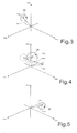
Figures 3-5 show representations, in the space of accelerations, of accelerations acting on the portable apparatus ofFigure 1 and of threshold regions associated thereto; -
Figure 6 is a flowchart corresponding to operations implemented by the device for detecting events ofFigure 2 ; -
Figures 7 and 8 show further representations of accelerations acting on theportable apparatus 1; and -
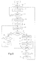
Figure 9 is a flowchart corresponding to operations implemented by the device for detecting events ofFigure 2 , according to a different embodiment of the present invention. - As shown in
Figure 1 , aportable apparatus 1, for example a portable computer (laptop), a PDA (Personal Data Assistant), a digital audio player, a mobile phone, a digital camcorder or photographic camera, a satellite navigator, or the like, includes amicroprocessor control circuit 2, designed to control the general operation thereof, and a hard-disk device 3, operatively coupled to themicroprocessor control circuit 2 for writing and reading data. In a per-se known manner, the hard-disk device 3 is provided with a read/writehead 4 and astorage medium 5, associated to the read/writehead 4. - The
portable apparatus 1 further comprises adetection device 6 for detecting anomalous events associated to the portable apparatus, the detection device being provided for this purpose with: anaccelerometer sensor 7, designed to detect one or more acceleration signals Acc corresponding to accelerations acting on theportable apparatus 1; and aprocessing circuit 8, connected to theaccelerometer sensor 7 and designed to process the acceleration signals Acc in order to detect an anomalous event. For example, thedetection device 6 can be configured to generate, when detecting an anomalous event, an interrupt signal INT, and to supply it, continuously and in real time, to themicroprocessor control circuit 2 for enabling immediate activation of appropriate actions of protection (for example, parking of the read/writehead 4 of the hard-disk device 3). Alternatively (and as is indicated schematically by thedashed arrow 9 ofFigure 1 ), thedetection device 6 can be configured to directly carry out appropriate actions of protection, and to issue suitable control signals, e.g. for parking the read/writehead 4. - The
detection device 6 is integrated within theportable apparatus 1; for example, it can be provided in a chip and coupled to a printed circuit set within theportable apparatus 1, to which also themicroprocessor control circuit 2 is coupled. - In greater detail, the
accelerometer sensor 7 is a MEMS inertial sensor, made, for example, as described in "3-axis digital output accelerometer for future automotive applications", B. Vigna et al., AMAA 2004, which detects the components of the acceleration acting on theportable apparatus 1 directed along the three axes X, Y, Z of a set of three Cartesian axes fixed with respect to theportable apparatus 1, and supplies respective acceleration signals Accx, Accy, and Accz (designated as a whole as acceleration signals Acc). - According to an aspect of the present invention, the
detection device 6 is configured to monitor a normal-mode condition of theportable apparatus 1 and to detect an anomalous event as an exit from the normal-mode condition. In particular, as will be described in detail hereinafter, thedetection device 6 considers the variations of an acceleration acting on the portable apparatus 1 (for example, variations between a current value and a previous value of acceleration) and determines a permanence within the normal-mode condition when these variations are below a pre-set threshold. The threshold value depends, for example, on the type of portable apparatus, on the type of movements (and accelerations), and on the environmental conditions normally associated to its use. Preferably, thedetection device 6 also evaluates the duration of stay of theportable apparatus 1 outside the normal-mode condition, and detects an anomalous event when this duration is longer than a pre-set time interval (the value of which is again a function of the type and conditions of use of the portable apparatus). -
Figure 2 shows an embodiment of theprocessing circuit 8 according to a first embodiment of the present invention. - In detail, the
processing circuit 8 comprises: afirst filtering stage 10, implementing a low-pass (LP) filter of a finite-impulse-response (FIR) type, which is connected to theaccelerometer sensor 7 and supplies at output a first filtered acceleration signal Acc1 (reference is made here, for simplicity, to the acceleration signal Acc as a whole and not to the corresponding acceleration components Accx, Accy and Accz, but it is clear that similar considerations apply to the acceleration components); asecond filtering stage 11, implementing a low-pass infinite-impulse-response (IIR) filter, which is connected to theaccelerometer sensor 7, supplies at output a second filtered acceleration signal Acc2, and has a cut-off frequency lower than that of the aforesaid FIR filter; and acombination stage 12, which has a first input and a second input, respectively connected to the output of thefirst filtering stage 10 and of thesecond filtering stage 11, and supplies at output a combination signal, which is a function of the first and second filtered acceleration signals. In particular, thecombination stage 12 implements a subtractor stage and is configured to supply an acceleration-variation signal ΔAcc (shown inFigure 4 ), given by the difference between the first filtered acceleration signal Acc1 and the second filtered acceleration signal Acc2. - The
processing circuit 8 further comprises: acomparator stage 14, connected to the output of thecombination stage 12 and designed to compare the value of the acceleration-variation signal ΔAcc (in particular a magnitude thereof, given by the combination of the contributions of the components along the three axes X, Y and Z) with an acceleration threshold THA, having a value that can vary, as will be described hereinafter, between a minimum value THA1 and a maximum value THA2, and to supply at output a comparison signal having a logic value; a threshold-variation stage 15, connected to the output of thecomparator stage 14 and designed to vary the value of the acceleration threshold THA as a function of the value of the comparison signal; acounter stage 16, which is connected to the output of thecomparator stage 14, receives the comparison signal at a count-enable input, and supplies at output a count signal; and adetection stage 18, which is connected to the output of thecomparator stage 14 and of thecounter stage 16 and is designed to supply at output the interrupt signal INT according to the value of the comparison signal and of the count signal. - The threshold-
variation stage 15 is configured to vary dynamically the value of the acceleration threshold THA, gradually between the minimum value THA1 and the maximum value THA2, or vice versa (according to whether the comparison signal switches from a first value, e.g. a low value or logic "0", to a second value, e.g. a high value or logic "1", or vice versa). - The
detection stage 18 is configured to set the interrupt signal INT to a given value (for example, a high logic value) upon detection of an anomalous event. In particular, the anomalous event is detected when the comparison signal has a given value, in particular a high value, and moreover the count signal is higher than a given time threshold THT (which can, for example, be set from outside by a user). - Operation of the
processing circuit 8 for detecting an anomalous event is now described with reference toFigures 3-5 , which show a three-dimensional space of accelerations in which the acceleration signals Acc and the acceleration-variation signal ΔAcc are represented. - In particular, the instantaneous value of the first filtered acceleration signal Acc1 is represented by a first point P within the space of accelerations (with co-ordinates corresponding to its acceleration components Accx, Accy and Accz), and its magnitude is represented by the distance of the first point P from the origin O of the axes. Variations of the resultant acceleration acting on the
portable apparatus 1 correspond to displacements of the first point P within the space of accelerations. The instantaneous value of the second filtered acceleration signal Acc2 is represented by a second point P', which also is the centre of a spherical region having a radius equal to the minimum value THA1 of the acceleration threshold THA. The spherical region represents a threshold region indicating a normal-mode condition of theportable apparatus 1 and is consequently referred to in what follows as normal-mode region 20. Variations of acceleration that keep the first point P within the normal-mode region 20 (and hence the acceleration-variation signal ΔAcc lower than the acceleration threshold THA) are indicative of a normal operation of theportable apparatus 1. In addition, in a condition of rest of the portable apparatus 1 (as shown inFigure 3 ), the second point P' coincides with the first point P. - A variation of acceleration (
Figure 4 ) of anomalous extent (for example, due to a free-fall condition, to a violent shock, or to high vibrations) causes the point P to exit from the normal-mode region 20. The acceleration-variation signal ΔAcc exceeds the acceleration threshold THA, and the comparison signal at output from thecomparator stage 14 goes to the high value. This event is interpreted by theprocessing circuit 8 of thedetection device 6 as potentially indicating an anomalous event. However, for an anomalous event to be actually detected, the permanence outside the normal-mode condition has still to be verified for a pre-set period of time (the duration check) equal to the time threshold THT. Thecounter stage 16 is consequently enabled for counting by switching of the comparison signal. - Given that the second point P' is a result of the filtering operation carried out in the
second filtering stage 11 by the IIR filter having a cut-off frequency lower than the FIR filter of thefirst filtering stage 10, the second point P' follows the displacements of the first point P with a certain delay. In general, the first point P represents a current value, whilst the second point P' represents a previous value of the acceleration acting on theportable apparatus 1. The normal-mode region 20 follows, also with a delay, the displacement of the first point P. It should be noted that the rate of displacement of the normal-mode region 20 depends on the implementation of the IIR filter and its different cut-off frequency with respect to that of the FIR filter (in particular, and in a per-se known manner, it depends on a "weight" attributed to a current sample of the acceleration data as compared to that attributed to one or more previous samples). - Switching of the comparison signal causes the threshold-
variation stage 15 to vary the acceleration threshold THA to the maximum value THA2. The normal-mode region 20 is consequently enlarged, and its radius is increased until it becomes (either instantaneously or gradually) equal to the maximum value THA2. In addition, switching of the comparison signal enables thecounter stage 16 and starts the count signal. When the value of the count signal becomes higher than the time threshold THT, thedetection stage 18 identifies an anomalous event and sets (for example to the high logic value) the interrupt signal INT. - The normal-
mode region 20 then moves until its centre (second point P') coincides again with the first point P (Figure 5 ) (corresponding to a new condition of rest of the portable apparatus 1). - The
processing circuit 8 detects re-entry of the first point P within the normal-mode region 20 upon switching of the comparison signal to the low value, and brings the interrupt signal INT back again to the low value. This event causes blocking of the count signal at output from thecounter stage 16, thus defining the total duration of permanence in an anomalous operating condition, and also the return of the normal-mode region 20 to the original dimensions, with a radius equal to the minimum value THA1 of the acceleration threshold THA. - In particular, the enlargement of the normal-
mode region 20 and the increase of the corresponding radius from the minimum value THA1 to the maximum value THA2 advantageously prevents repeated variations of acceleration having a value slightly higher than the minimum value THA1 (i.e., located at the edge of the spherical region, in the space of accelerations) from being interpreted as anomalous events and giving rise to false-triggering events. In addition, as may be readily understood, variations of acceleration of a high value (and hence potentially dangerous) entail a greater duration of the time interval for re-entry of the first point P within the normal-mode region 20 and hence give rise to the identification of anomalous events. - In brief, and with reference to the flowchart of
Figure 6 , the algorithm described envisages at start an initialization step (block 21), in which, in particular, the normal-mode region 20 is centred on the first point P (so that upon turning-on no anomalous operating condition is detected). - Next, a continuous monitoring of the value of the acceleration-variation signal ΔAcc is implemented (block 22), which is indicative of the variation of acceleration between a current condition and a previous condition of the
portable apparatus 1 so as to verify the permanence of theportable apparatus 1 in a normal-mode condition (block 23). - As soon as a variation of acceleration is detected higher than (or equal to) the acceleration threshold THA (initially set at the minimum value THA1), which indicates exit from the normal-mode condition, the value of the acceleration threshold is varied gradually from the minimum value THA1 to the maximum value THA2 (block 24), and a count (CONT) of the duration of permanence in the anomalous condition of operation (block 25) is started.
- The procedure then waits for the return of the
portable apparatus 1 into the normal-mode condition, while the acceleration-variation signal ΔAcc (block 26) is again monitored and compared with the acceleration threshold THA (block 27). - During permanence in the anomalous operation condition, a check is made as to whether the count value (which is incremented as a function of an internal clock) exceeds the time threshold THT (block 28). If it does, an anomalous event is detected, and the interrupt signal INT is set to the high value (block 29). Then the procedure again waits for the return of the device into a normal-mode condition (blocks 26 and 27).
- Upon entry into the normal-mode condition, the value of the acceleration threshold is gradually varied from the maximum value THA2 to the minimum value THA1 (block 30), and the interrupt signal INT returns to the low value (block 31). The algorithm then returns into a state of waiting for a new anomalous event (block 22).
- The advantages that the device and the method for detecting anomalous events enable are clear from what has been described and illustrated above.
- In particular, by monitoring exit of the
portable apparatus 1 from a normal-mode condition, it is possible to detect a generic anomalous event, unlike traditional methods, which are focused on the identification of a particular type of anomalous event (for example, a free fall or a shock). The safety and possibility of protection of the portable apparatuses in the case of anomalous events is thus increased. In addition, the condition of normal use can advantageously be set and configured from outside, enabling adaptation to the particular type of portable apparatus in which the detection device is incorporated and to the environmental conditions associated to the use of the same portable apparatus. In the circuit embodiment described, it is possible, for example, to vary the minimum and maximum values of the acceleration threshold THA, the value of the time threshold THT, and the parameters and the cut-off frequency of the IIR filter in thesecond filtering stage 11. For example, in order to limit the number of false detections, the difference between the maximum value and the minimum value of the acceleration threshold THA will be generally greater when the portable apparatus is used in a noisy environment, or else, the speed of the IIR filter will be generally higher for a portable apparatus, e.g. a mobile phone, which is subject to displacements of a greater amount. - Checking the exit from the normal-mode condition enables monitoring (by successive comparisons with one or more thresholds) not of the absolute value of the accelerations acting on the
portable apparatus 1, but rather of the acceleration variations (or in other words the displacements in the space of accelerations). In this way, the problems associated to the presence of offsets in theaccelerometer sensor 7 and to the development of centrifugal acceleration (roll effect) are avoided. In fact, as represented inFigures 7 and 8 , which again refer to the space of accelerations, an offset or a centrifugal acceleration will not alter detection of an anomalous event (in the specific case, a free fall). In detail (Figure 7 ), an offset of theaccelerometer sensor 7 causes a variation of the acceleration detected in the resting condition (point Poff displaced with respect to the ideal position, designated by P). The offset also causes a change in the position of arrival in the case of free fall, which does not coincide with the origin of the axes (the position in the absence of offsets is represented with a dashed line). The presence of offsets does not alter, however, the degree of the variation of acceleration that occurs upon the free fall. Consequently, the described algorithm, by comparing the variation of acceleration (or the displacement of the point P), and not the absolute value of acceleration, is not altered. Likewise (Figure 8 ), the presence of a centrifugal acceleration varies the point of arrival of the point P after free fall, which does not reach the origin of the axes, but a different point, designated by PROLL. Advantageously, also in this case, the algorithm detects exit of the point P from the normal-mode region 20 (and hence the anomalous event), without being deceived by development of the centrifugal acceleration. - It is therefore possible to detect anomalous events associated to the
portable apparatus 1 with a high degree of reliability, and hence guarantee with certainty the protection of the portable apparatus. In addition, the circuit complexity and the consequent area occupation of the detection device 6 (in the case of hardware implementation), or the computing power required by the detection algorithm (in the case of software implementation) are extremely limited. - Finally, it is clear that modifications and variations may be made to what is described and illustrated herein, without thereby departing from the scope of the present invention, as defined in the annexed claims.
- In particular, the algorithm implemented by the
detection device 6 can envisage that, upon re-entry into the normal-mode condition, the interrupt signal INT goes back again to the low value not instantaneously, but with a certain delay, given by a further count (which can also be implemented by the counter stage 16). This variant is particularly advantageous for remaining in a state of alert and monitoring the anomalous event also in the case where the portable apparatus returns for a short period into a normal-mode condition and then exits again therefrom on account of a further anomalous event that is close in time. This situation can, in fact, indicate an imminent impact or other destructive event (that the algorithm described previously might not detect with a sufficient readiness). -
Figure 9 shows a flowchart regarding this variant, which basically coincides with the one described inFigure 6 , except as regards a reset procedure of the interrupt signal INT. In detail, upon return of theportable apparatus 1 into the normal-mode condition (output YES from block 27), in addition to the variation of the acceleration threshold value from the maximum value THA2 to the minimum value THA1 (block 30), a further count (CONT') is started for detecting the duration of permanence in the normal-mode condition (block 32). Then the value of the acceleration-variation signal ΔAcc is monitored again (block 33) so as to verify the permanence of theportable apparatus 1 in a normal-mode condition (block 34). During the permanence in this condition, a check is made as to whether the value of the further count exceeds a further time threshold THT' (block 35). If it does, the interrupt signal INT is brought back again to the low value (block 31, described previously), and the algorithm returns into a state of wait for a new anomalous event (block 22). Instead, if a new exit from the normal-mode condition is determined (output NO from block 34), the algorithm returns to block 28 so as to continue monitoring of the anomalous event (basically, the momentary return of theportable apparatus 1 into a normal-mode condition is ignored by the algorithm). - In addition, the
processing circuit 8 may be modified so as to determine not only the occurrence of an anomalous event, but also the type of the anomalous event, by means of additional processing operations on the acceleration signals Acc. For example, in order to identify a free-fall event, theprocessing circuit 8 could be configured to determine a decrease of the magnitude of the acceleration signal Acc in the current condition, as compared to the previous condition, higher than a given threshold (in the case of free fall, in fact, the components of the acceleration signal Acc ideally go to zero). - The variation of the acceleration signal could be determined in a way different from what has been illustrated and described. In addition, filtering of the acceleration signal Acc in the
first filtering stage 10 could be omitted. - The further control on the duration of permanence of the
portable apparatus 1 in an anomalous condition of operation could not be present in given applications and with a given choice of the minimum and maximum values of the acceleration threshold THA. - In addition, the
processing circuit 8 could be modified so as to implement different acceleration thresholds along the axes X, Y, Z, and the normal-mode region 20 could consequently have a shape different from the spherical shape described and illustrated.
Claims (23)
- A method for detecting anomalous events in an electronic apparatus (1), comprising:- generating at least one acceleration signal (Acc) indicative of an acceleration acting on said electronic apparatus (1); and- detecting an anomalous event as a function of said acceleration signal (Acc),characterized in that said step of detecting an anomalous event comprises:- monitoring a normal-mode condition of said electronic apparatus (1); and- detecting said anomalous event at least based on the exit of said electronic apparatus (1) from said normal-mode condition.
- The method according to claim 1, wherein said step of monitoring a normal-mode condition comprises:- determining a variation of acceleration (ΔAcc) associated to said acceleration signal (Acc);- executing a comparison between said variation of acceleration (ΔAcc) and an acceleration threshold (THA); and- determining the permanence in, or exit from, said normal-mode condition according to the result of said comparison.
- The method according to claim 2, wherein said step of monitoring a normal-mode condition further comprises setting the value of said acceleration threshold (THA) as a function of given characteristics of said electronic apparatus (1).
- The method according to claim 2 or 3, wherein said step of determining said variation of acceleration (ΔAcc) comprises determining a variation between a current value and a previous value of said acceleration signal (Acc).
- The method according to any one of claims 2-4, wherein said step of determining said variation of acceleration (ΔAcc) comprises:- filtering said acceleration signal (Acc) with a filter (11) having a given cut-off frequency so as to obtain a filtered acceleration signal (Acc2); and- determining said variation of acceleration (ΔAcc) as a difference between a signal (Acc1) correlated to said acceleration signal (Acc) and said filtered acceleration signal (Acc2).
- The method according to claim 5, wherein said step of determining said variation of acceleration (ΔAcc) further comprises filtering said acceleration signal (Acc) with a further filter (10) having a cut-off frequency higher than said given cut-off frequency so as to obtain said signal (Acc1) correlated to said acceleration signal (Acc).
- The method according to any one of claims 2-6, wherein said step of detecting said anomalous event further comprises:- determining a first duration of permanence of said electronic apparatus (1) outside said normal-mode condition; and- detecting said anomalous event also as a function of said first duration of permanence.
- The method according to claim 7, wherein said step of detecting said anomalous event further comprises:- determining, upon entry into said normal-mode condition, a second duration of permanence of said electronic apparatus (1) in said normal-mode condition; and- detecting said anomalous event also as a function of said second duration of permanence.
- The method according to any one of claims 2-8, wherein said step of detecting said anomalous event further comprises: varying dynamically the value of said acceleration threshold (THA) according to the result of said comparison.
- The method according to claim 9, wherein said step of varying dynamically the value of said acceleration threshold (THA) comprises increasing the value of said acceleration threshold (THA) from a lower value (THA1) to a higher value (THA2) upon exit from said normal-mode condition, and decreasing the value of said acceleration threshold (THA) from said higher value to said lower value, upon entry into said normal-mode condition.
- A device for detecting (6) anomalous events in an electronic apparatus (1), comprising:- an accelerometer sensor (7), designed to detect at least one acceleration signal (Acc) indicative of an acceleration acting on said electronic apparatus (1); and- a processing circuit (8), configured to detect said anomalous event as a function of said acceleration signal (Acc),characterized in that said processing circuit (8) comprises:- a monitoring stage (10, 11, 12, 14), configured to monitor a normal-mode condition of said electronic apparatus (1); and- a detection stage (15, 16, 18), coupled to said monitoring stage, and configured to detect said anomalous event at least based on the exit of said electronic apparatus (1) from said normal-mode condition.
- The device according to claim 11, wherein said monitoring stage (10, 11, 12, 14) comprises determination means (10, 11, 12) for determining a variation of acceleration (ΔAcc) associated to said acceleration signal (Acc), and comparison means (14) for comparing said variation of acceleration (ΔAcc) with an acceleration threshold (THA); and said detection stage (15, 16, 18) is configured to determine the permanence in, or exit from, said normal-mode condition according to the result of said comparison.
- The device according to claim 12, wherein said monitoring stage (10, 11, 12, 14) further comprises setting means, operable to set the value of said acceleration threshold (THA) according to given characteristics of said electronic apparatus (1).
- The device according to claim 12 or 13, wherein said determination means (10, 11, 12) are configured so as to determine a variation between a substantially current value and a previous value of said acceleration signal (Acc).
- The device according to any one of Claims 12-14, wherein said determination means (10, 11, 12) comprise: filtering means (11) configured to filter said acceleration signal (Acc) with a given cut-off frequency so as to generate a filtered acceleration signal (Acc2); and subtractor means (12), configured to determine said variation of acceleration (ΔAcc) as a difference between a signal (Acc1) correlated to said acceleration signal (Acc) and said filtered acceleration signal (Acc2).
- The device according to claim 15, wherein said determination means (10, 11, 12) further comprise further filtering means (10) configured to generate said signal (Acc1) correlated to said acceleration signal (Acc); said filtering means (11) having a cut-off frequency lower than said further filtering means (10).
- The device according to claim 16, wherein said filtering means (11) include an IIR filter and said further filtering means (10) include a FIR filter.
- The device according to any one of claims 12-17, wherein said detection stage (15, 16, 18) further comprises a counter stage (16), designed to determine a duration of permanence of said apparatus (1) outside said normal-mode condition; said detection stage (15, 16, 18) configured to detect said anomalous event also as a function of said duration of permanence.
- The device according to any one of claims 12-18, wherein said detection stage (15, 16, 18) further comprises a threshold-variation stage (15), configured to vary dynamically the value of said acceleration threshold (THA) according to the result of said comparison.
- The device according to claim 19, wherein said threshold-variation stage (15) is configured to increase the value of said acceleration threshold (THA) from a lower value (THA1) to a higher value (THA2) upon exit from said normal-mode condition, and decrease the value of said acceleration threshold (THA) from said higher value to said lower value upon entry into said normal-mode condition.
- The device according to any one of claims 12-20 for an electronic apparatus (1) provided with a device (3) to be protected from said anomalous event, further comprising protection means (9) designed to perform operations of protection of said device (3) upon detection of said anomalous event.
- An electronic apparatus (1), characterized by comprising a detection device (6) according to any one of claims 11-21, in particular said electronic apparatus (1) being a portable apparatus chosen in the group comprising: a portable computer, a PDA, a digital audio player, a mobile phone, a digital camcorder or photographic camera, and a satellite navigator.
- The apparatus according to claim 22, further comprising a hard-disk device (3) and a control circuit (2) connected to said hard-disk device (3); said detection device (6) being configured to supply to said control circuit (2) a detection signal (INT), having a given value, upon detection of said anomalous event, and said control circuit (2) being configured to activate a given action of protection of said hard-disk device (3) upon reception of said detection signal (INT) with said given value.
Priority Applications (2)
| Application Number | Priority Date | Filing Date | Title |
|---|---|---|---|
| EP08425029.9A EP2083276B1 (en) | 2008-01-22 | 2008-01-22 | Method and device for detecting anomalous events for an electronic apparatus, in particular a portable apparatus |
| US12/357,620 US7979235B2 (en) | 2008-01-22 | 2009-01-22 | Method and device for detecting anomalous events for an electronic apparatus, in particular a portable apparatus |
Applications Claiming Priority (1)
| Application Number | Priority Date | Filing Date | Title |
|---|---|---|---|
| EP08425029.9A EP2083276B1 (en) | 2008-01-22 | 2008-01-22 | Method and device for detecting anomalous events for an electronic apparatus, in particular a portable apparatus |
Publications (2)
| Publication Number | Publication Date |
|---|---|
| EP2083276A1 true EP2083276A1 (en) | 2009-07-29 |
| EP2083276B1 EP2083276B1 (en) | 2014-10-29 |
Family
ID=39494422
Family Applications (1)
| Application Number | Title | Priority Date | Filing Date |
|---|---|---|---|
| EP08425029.9A Active EP2083276B1 (en) | 2008-01-22 | 2008-01-22 | Method and device for detecting anomalous events for an electronic apparatus, in particular a portable apparatus |
Country Status (2)
| Country | Link |
|---|---|
| US (1) | US7979235B2 (en) |
| EP (1) | EP2083276B1 (en) |
Cited By (10)
| Publication number | Priority date | Publication date | Assignee | Title |
|---|---|---|---|---|
| WO2014081485A1 (en) | 2012-11-21 | 2014-05-30 | Calamp Corp. | Systems and methods for efficient characterization of acceleration events |
| TWI471811B (en) * | 2010-09-08 | 2015-02-01 | Apple Inc | Camera-based orientation correction from portrait to landscape |
| US10102689B2 (en) | 2012-10-18 | 2018-10-16 | Calamp Corp | Systems and methods for location reporting of detected events in vehicle operation |
| US10219117B2 (en) | 2016-10-12 | 2019-02-26 | Calamp Corp. | Systems and methods for radio access interfaces |
| US10395438B2 (en) | 2016-08-19 | 2019-08-27 | Calamp Corp. | Systems and methods for crash determination with noise filtering |
| US10466269B2 (en) | 2013-02-19 | 2019-11-05 | Calamp Corp. | Systems and methods for low latency 3-axis accelerometer calibration |
| US10473750B2 (en) | 2016-12-08 | 2019-11-12 | Calamp Corp. | Systems and methods for tracking multiple collocated assets |
| US10599421B2 (en) | 2017-07-14 | 2020-03-24 | Calamp Corp. | Systems and methods for failsafe firmware upgrades |
| US11570529B2 (en) | 2016-07-08 | 2023-01-31 | CalAmpCorp. | Systems and methods for crash determination |
| US11924303B2 (en) | 2017-11-06 | 2024-03-05 | Calamp Corp. | Systems and methods for dynamic telematics messaging |
Families Citing this family (12)
| Publication number | Priority date | Publication date | Assignee | Title |
|---|---|---|---|---|
| CN102610228B (en) * | 2011-01-19 | 2014-01-22 | 上海弘视通信技术有限公司 | Audio exception event detection system and calibration method for the same |
| US9818281B2 (en) * | 2011-11-14 | 2017-11-14 | Vital Connect, Inc. | Method and system for fall detection of a user |
| US9588135B1 (en) | 2011-11-14 | 2017-03-07 | Vital Connect, Inc. | Method and system for fall detection of a user |
| US8614630B2 (en) * | 2011-11-14 | 2013-12-24 | Vital Connect, Inc. | Fall detection using sensor fusion |
| US10395221B1 (en) * | 2014-06-26 | 2019-08-27 | Amazon Technologies, Inc. | Providing rewards to encourage device care |
| US9746930B2 (en) | 2015-03-26 | 2017-08-29 | General Electric Company | Detection and usability of personal electronic devices for field engineers |
| JP6227603B2 (en) * | 2015-09-10 | 2017-11-08 | ファナック株式会社 | Electronic equipment with impact detection function |
| JP6846991B2 (en) * | 2016-07-05 | 2021-03-24 | パナソニック インテレクチュアル プロパティ コーポレーション オブ アメリカPanasonic Intellectual Property Corporation of America | Anomaly detection electronic control unit, in-vehicle network system and anomaly detection method |
| CN108572689B (en) * | 2017-03-10 | 2020-09-22 | 台达电子企业管理(上海)有限公司 | Switching power supply, over-temperature control protection method and power control method |
| US11255875B2 (en) * | 2020-02-18 | 2022-02-22 | Stmicroelectronics Asia Pacific Pte Ltd. | System and method for determining distance of free fall |
| CN115119301B (en) * | 2021-03-23 | 2023-11-17 | 北京小米移动软件有限公司 | Information processing method and device, communication equipment and storage medium |
| CN114993461B (en) * | 2022-08-08 | 2022-11-04 | 成都久和建设设备有限责任公司 | System and method for detecting vibration of motor of tower crane mechanism |
Citations (5)
| Publication number | Priority date | Publication date | Assignee | Title |
|---|---|---|---|---|
| US20050141127A1 (en) * | 2003-12-26 | 2005-06-30 | Susumu Shimotono | Method, apparatus and program storage device for magnetic disk drive protection |
| US20060136168A1 (en) * | 2004-12-17 | 2006-06-22 | Kabushiki Kaisha Toshiba | Electronic apparatus and disk protection method |
| US20060268447A1 (en) * | 2005-05-09 | 2006-11-30 | Wenshuai Liao | Accelerometer-based differential free fall detection system, apparatus, and method and disk drive protection mechanism employing same |
| US20070118326A1 (en) * | 2005-11-09 | 2007-05-24 | Dmitry Starodubtsev | Method for compensating for acceleration vector offset, recording medium storing program for executing the method, and related apparatus |
| US20070177295A1 (en) * | 2005-12-28 | 2007-08-02 | Sony Corporation | Information processing apparatus having built-in hard disk drive and head retraction processing method of built-in hard disk drive |
Family Cites Families (7)
| Publication number | Priority date | Publication date | Assignee | Title |
|---|---|---|---|---|
| US5982573A (en) * | 1993-12-15 | 1999-11-09 | Hewlett-Packard Company | Disk drive and method for minimizing shock-induced damage |
| JP3518509B2 (en) * | 2000-12-28 | 2004-04-12 | トヨタ自動車株式会社 | Rollover judgment device |
| KR100446612B1 (en) * | 2001-07-24 | 2004-09-04 | 삼성전자주식회사 | Method and apparatus for selecting information in multi-dimensional space |
| US7042663B2 (en) * | 2002-10-03 | 2006-05-09 | Hitachi Global Storage Technologies Netherlands B.V. | Magnetic disk protection mechanism, computer system comprising protection mechanism, protection method for magnetic disk, and program for protection method |
| JP4283313B2 (en) * | 2004-11-05 | 2009-06-24 | インターナショナル・ビジネス・マシーンズ・コーポレーション | Motion detection device and motion detection method |
| WO2008143738A1 (en) * | 2007-05-18 | 2008-11-27 | Ultimate Balance, Inc. | Newtonian physical activity monitor |
| US20090021858A1 (en) * | 2007-07-17 | 2009-01-22 | Guoyi Fu | Hard Disk Drive Protection System Based on Adaptive Thresholding |
-
2008
- 2008-01-22 EP EP08425029.9A patent/EP2083276B1/en active Active
-
2009
- 2009-01-22 US US12/357,620 patent/US7979235B2/en active Active
Patent Citations (5)
| Publication number | Priority date | Publication date | Assignee | Title |
|---|---|---|---|---|
| US20050141127A1 (en) * | 2003-12-26 | 2005-06-30 | Susumu Shimotono | Method, apparatus and program storage device for magnetic disk drive protection |
| US20060136168A1 (en) * | 2004-12-17 | 2006-06-22 | Kabushiki Kaisha Toshiba | Electronic apparatus and disk protection method |
| US20060268447A1 (en) * | 2005-05-09 | 2006-11-30 | Wenshuai Liao | Accelerometer-based differential free fall detection system, apparatus, and method and disk drive protection mechanism employing same |
| US20070118326A1 (en) * | 2005-11-09 | 2007-05-24 | Dmitry Starodubtsev | Method for compensating for acceleration vector offset, recording medium storing program for executing the method, and related apparatus |
| US20070177295A1 (en) * | 2005-12-28 | 2007-08-02 | Sony Corporation | Information processing apparatus having built-in hard disk drive and head retraction processing method of built-in hard disk drive |
Cited By (19)
| Publication number | Priority date | Publication date | Assignee | Title |
|---|---|---|---|---|
| TWI471811B (en) * | 2010-09-08 | 2015-02-01 | Apple Inc | Camera-based orientation correction from portrait to landscape |
| US8958004B2 (en) | 2010-09-08 | 2015-02-17 | Apple Inc. | Camera-based orientation fix from portrait to landscape |
| US9565365B2 (en) | 2010-09-08 | 2017-02-07 | Apple Inc. | Camera-based orientation fix from portrait to landscape |
| US10102689B2 (en) | 2012-10-18 | 2018-10-16 | Calamp Corp | Systems and methods for location reporting of detected events in vehicle operation |
| EP2923277A4 (en) * | 2012-11-21 | 2016-04-13 | Calamp Corp | SYSTEMS AND METHODS FOR EFFICIENT CHARACTERIZATION OF ACCELERATION EVENTS |
| EP3196771A1 (en) * | 2012-11-21 | 2017-07-26 | Calamp Corp. | Systems and methods for efficient characterization of acceleration events |
| US10107831B2 (en) | 2012-11-21 | 2018-10-23 | Calamp Corp | Systems and methods for efficient characterization of acceleration events |
| WO2014081485A1 (en) | 2012-11-21 | 2014-05-30 | Calamp Corp. | Systems and methods for efficient characterization of acceleration events |
| US11480587B2 (en) | 2013-02-19 | 2022-10-25 | CalAmpCorp. | Systems and methods for low latency 3-axis accelerometer calibration |
| US10466269B2 (en) | 2013-02-19 | 2019-11-05 | Calamp Corp. | Systems and methods for low latency 3-axis accelerometer calibration |
| US11570529B2 (en) | 2016-07-08 | 2023-01-31 | CalAmpCorp. | Systems and methods for crash determination |
| US10395438B2 (en) | 2016-08-19 | 2019-08-27 | Calamp Corp. | Systems and methods for crash determination with noise filtering |
| US10219117B2 (en) | 2016-10-12 | 2019-02-26 | Calamp Corp. | Systems and methods for radio access interfaces |
| US10645551B2 (en) | 2016-10-12 | 2020-05-05 | Calamp Corp. | Systems and methods for radio access interfaces |
| US11022671B2 (en) | 2016-12-08 | 2021-06-01 | Calamp Corp | Systems and methods for tracking multiple collocated assets |
| US10473750B2 (en) | 2016-12-08 | 2019-11-12 | Calamp Corp. | Systems and methods for tracking multiple collocated assets |
| US11436002B2 (en) | 2017-07-14 | 2022-09-06 | CalAmpCorp. | Systems and methods for failsafe firmware upgrades |
| US10599421B2 (en) | 2017-07-14 | 2020-03-24 | Calamp Corp. | Systems and methods for failsafe firmware upgrades |
| US11924303B2 (en) | 2017-11-06 | 2024-03-05 | Calamp Corp. | Systems and methods for dynamic telematics messaging |
Also Published As
| Publication number | Publication date |
|---|---|
| EP2083276B1 (en) | 2014-10-29 |
| US7979235B2 (en) | 2011-07-12 |
| US20090187370A1 (en) | 2009-07-23 |
Similar Documents
| Publication | Publication Date | Title |
|---|---|---|
| EP2083276B1 (en) | Method and device for detecting anomalous events for an electronic apparatus, in particular a portable apparatus | |
| US7450332B2 (en) | Free-fall detection device and free-fall protection system for a portable electronic apparatus | |
| JP5064235B2 (en) | System and method for fall detection | |
| JP3441668B2 (en) | Drop detection mechanism, magnetic disk drive protection mechanism, and portable equipment | |
| US7672806B2 (en) | Displacement detection device for a portable apparatus | |
| JP4637165B2 (en) | Fall detection method and fall detection device | |
| US7451057B2 (en) | System and method for detection of freefall with spin using two tri-axis accelerometers | |
| JP5067257B2 (en) | Information device to detect fall | |
| US8164847B2 (en) | Fall detection device, magnetic disk device, and portable electronic apparatus | |
| US8612810B2 (en) | Sensor device provided with a circuit for detection of single or multiple events for generating corresponding interrupt signals | |
| CN102841818A (en) | Electronic device avoiding false detection of free fall event based on detected operating mode | |
| EP1612565B1 (en) | Free-fall detection device and free-fall protection system for a portable electronic apparatus | |
| CA2590248C (en) | Motion detection apparatus and motion detecting method | |
| JP2009528523A (en) | Method and apparatus for identifying free fall | |
| US7626355B2 (en) | Portable electronic device and method to protect same | |
| JP4434208B2 (en) | Fall detection device and magnetic disk device | |
| CN102099859A (en) | Drop detection device, magnetic disc device, and mobile electronic device | |
| JP2005037300A (en) | Portable equipment having acceleration history recording function, and acceleration sensor device used for the same | |
| US7782219B2 (en) | Device and method for protecting an electronic appliance in critical motion conditions, in particular in case of fall | |
| KR20060121368A (en) | Impact prediction device and method using acceleration sensor | |
| JP5024250B2 (en) | Fall detection device, magnetic disk device, and portable electronic device | |
| HK1139740A (en) | System and method for detection of freefall with spin using two tri-axis accelerometers | |
| JP2009272020A (en) | Disk driving device and method for specifying false detection of fall in disk driving device |
Legal Events
| Date | Code | Title | Description |
|---|---|---|---|
| PUAI | Public reference made under article 153(3) epc to a published international application that has entered the european phase |
Free format text: ORIGINAL CODE: 0009012 |
|
| AK | Designated contracting states |
Kind code of ref document: A1 Designated state(s): AT BE BG CH CY CZ DE DK EE ES FI FR GB GR HR HU IE IS IT LI LT LU LV MC MT NL NO PL PT RO SE SI SK TR |
|
| AX | Request for extension of the european patent |
Extension state: AL BA MK RS |
|
| 17P | Request for examination filed |
Effective date: 20100121 |
|
| 17Q | First examination report despatched |
Effective date: 20100217 |
|
| AKX | Designation fees paid |
Designated state(s): DE FR GB IT |
|
| RAP1 | Party data changed (applicant data changed or rights of an application transferred) |
Owner name: STMICROELECTRONICS SRL |
|
| RAP1 | Party data changed (applicant data changed or rights of an application transferred) |
Owner name: STMICROELECTRONICS SRL |
|
| REG | Reference to a national code |
Ref country code: DE Ref legal event code: R079 Ref document number: 602008035096 Country of ref document: DE Free format text: PREVIOUS MAIN CLASS: G01P0015080000 Ipc: G01P0001000000 |
|
| RIC1 | Information provided on ipc code assigned before grant |
Ipc: G01P 15/08 20060101ALI20140404BHEP Ipc: G01P 15/18 20130101ALI20140404BHEP Ipc: G01P 1/00 20060101AFI20140404BHEP Ipc: G01P 15/00 20060101ALI20140404BHEP Ipc: G11B 19/04 20060101ALI20140404BHEP |
|
| GRAP | Despatch of communication of intention to grant a patent |
Free format text: ORIGINAL CODE: EPIDOSNIGR1 |
|
| INTG | Intention to grant announced |
Effective date: 20140520 |
|
| GRAS | Grant fee paid |
Free format text: ORIGINAL CODE: EPIDOSNIGR3 |
|
| GRAA | (expected) grant |
Free format text: ORIGINAL CODE: 0009210 |
|
| AK | Designated contracting states |
Kind code of ref document: B1 Designated state(s): DE FR GB IT |
|
| REG | Reference to a national code |
Ref country code: GB Ref legal event code: FG4D |
|
| REG | Reference to a national code |
Ref country code: DE Ref legal event code: R096 Ref document number: 602008035096 Country of ref document: DE Effective date: 20141211 |
|
| REG | Reference to a national code |
Ref country code: DE Ref legal event code: R097 Ref document number: 602008035096 Country of ref document: DE |
|
| PG25 | Lapsed in a contracting state [announced via postgrant information from national office to epo] |
Ref country code: IT Free format text: LAPSE BECAUSE OF FAILURE TO SUBMIT A TRANSLATION OF THE DESCRIPTION OR TO PAY THE FEE WITHIN THE PRESCRIBED TIME-LIMIT Effective date: 20141029 |
|
| PLBE | No opposition filed within time limit |
Free format text: ORIGINAL CODE: 0009261 |
|
| STAA | Information on the status of an ep patent application or granted ep patent |
Free format text: STATUS: NO OPPOSITION FILED WITHIN TIME LIMIT |
|
| GBPC | Gb: european patent ceased through non-payment of renewal fee |
Effective date: 20150129 |
|
| 26N | No opposition filed |
Effective date: 20150730 |
|
| PG25 | Lapsed in a contracting state [announced via postgrant information from national office to epo] |
Ref country code: GB Free format text: LAPSE BECAUSE OF NON-PAYMENT OF DUE FEES Effective date: 20150129 |
|
| REG | Reference to a national code |
Ref country code: FR Ref legal event code: ST Effective date: 20150930 |
|
| PG25 | Lapsed in a contracting state [announced via postgrant information from national office to epo] |
Ref country code: FR Free format text: LAPSE BECAUSE OF NON-PAYMENT OF DUE FEES Effective date: 20150202 |
|
| P01 | Opt-out of the competence of the unified patent court (upc) registered |
Effective date: 20230504 |
|
| PGFP | Annual fee paid to national office [announced via postgrant information from national office to epo] |
Ref country code: DE Payment date: 20251217 Year of fee payment: 19 |