EP2083244A1 - Barometric-pressure-sensor device with altmeter function and altmeter-setting function - Google Patents
Barometric-pressure-sensor device with altmeter function and altmeter-setting function Download PDFInfo
- Publication number
- EP2083244A1 EP2083244A1 EP08425028A EP08425028A EP2083244A1 EP 2083244 A1 EP2083244 A1 EP 2083244A1 EP 08425028 A EP08425028 A EP 08425028A EP 08425028 A EP08425028 A EP 08425028A EP 2083244 A1 EP2083244 A1 EP 2083244A1
- Authority
- EP
- European Patent Office
- Prior art keywords
- pressure
- barometric
- measurement
- sensor
- processing circuit
- Prior art date
- Legal status (The legal status is an assumption and is not a legal conclusion. Google has not performed a legal analysis and makes no representation as to the accuracy of the status listed.)
- Granted
Links
Images

Classifications
-
- G—PHYSICS
- G01—MEASURING; TESTING
- G01C—MEASURING DISTANCES, LEVELS OR BEARINGS; SURVEYING; NAVIGATION; GYROSCOPIC INSTRUMENTS; PHOTOGRAMMETRY OR VIDEOGRAMMETRY
- G01C5/00—Measuring height; Measuring distances transverse to line of sight; Levelling between separated points; Surveyors' levels
- G01C5/06—Measuring height; Measuring distances transverse to line of sight; Levelling between separated points; Surveyors' levels by using barometric means
Definitions
- the present invention relates to a barometric-pressure-sensor device having an altimeter function and an altimeter-setting function, in particular designed to be integrated in portable electronic devices.
- electronic barometric altimeters including a pressure sensor, and a microprocessor control and processing circuit, designed to acquire and process pressure signals supplied by the pressure sensor for determining altitude information.
- Portable electronic devices are also known, such as, for example, mobile phones, satellite navigators or wrist watches, provided with a barometric-altimeter function. These devices include, for this purpose, a pressure sensor (for example, a pressure sensor of a MEMS type, as illustrated in Figure 1 ), supplying to a microprocessor of the portable electronic device barometric-pressure detection signals.
- the microprocessor in addition to controlling the general operation of the corresponding portable electronic device, processes the barometric-pressure detection signals for determining the altitude information.
- Figure 1 shows, by way of example, a known piezoresistive pressure sensor of a MEMS type.
- the use of this sensor in the aforesaid portable electronic devices can prove advantageous, given its small size.
- pressure sensor 1 comprises: a substrate 2 made of semiconductor material (typically silicon); a buried cavity 3, contained and insulated within the substrate 2; and a flexible membrane 4, suspended over the buried cavity 3 and bending in the presence of external mechanical stresses. Piezoresistive elements 5, connected in a Wheatstone-bridge configuration, are diffused in a surface portion of the flexible membrane 4 and contacted by metal regions 6 (which enable electrical connection of the pressure sensor 1 from the outside).
- the pressure sensor 1 may, for example, be manufactured as described in European patent application No. EP-A-1 577 656 , filed in the name of the present applicant.
- the top side of the flexible membrane 4 (i.e., the side opposite to the buried cavity 3) is set in communication with the outside environment. Consequently, the flexible membrane 4 is deformed as a function of the difference between the atmospheric pressure and the pressure present within the buried cavity 3, and this deformation causes unbalancing of the Wheatstone bridge formed by the piezoresistive elements 5; the desired pressure measurement is obtained from the unbalancing of the Wheatstone bridge.
- the corresponding microprocessor carries out the whole processing of the detection signals supplied by the pressure sensor 1 for altitude calculation, it is not possible to place the microprocessor in stand-by mode for reducing its power consumption, without forgoing the altimetric measurement function.
- power consumption issues are particularly relevant in portable electronic devices.
- microprocessors of portable electronic devices provided with the barometric-altimeter function are designed to perform for the most part of their operating period procedures for management of the general operation of the portable electronic devices. Consequently, processing of the detection signals supplied by the pressure sensor 1 has a low priority, causing a delay in the determination of the altitude information; this determination is in any case performed with an increase in the computational burden for the microprocessor, causing a degradation of the performance of the associated portable electronic device.
- microprocessors of portable electronic devices are often of a dedicated type, incorporated in ASICs (Application-Specific Integrated Circuits). Their operation is optimized for carrying out certain operations for which they have been designed, typically different from the ones linked to altimetric detection. This entails a considerable inefficiency in terms of time and computational load.
- ASICs Application-Specific Integrated Circuits
- the aim of the present invention is consequently to solve the aforementioned problems and disadvantages.
- a barometric-pressure-sensor device is provided as defined in claim 1.
- one aspect of the present invention envisages provision of a pressure sensor of a MEMS type and a corresponding electronic processing circuit, of a purely hardware type, within just one integrated circuit, which performs autonomously, without the aid of external microprocessors, altimeter and altimeter-setting operations.
- the "altimeter setting" expression denotes, particularly in the field of aeronautic navigation, the set of operations aimed at setting the altimetric measurement with respect to a given reference.
- this setting enables, via setting of the pressure value at the reference altitude, determination of the correct altitude with respect to the reference.
- the most widely known altimeter settings are the ones used by pilots and by air-traffic control (ATC), namely:
- the barometric-pressure-sensor device 20 comprises: a pressure sensor 1 of a MEMS type, in particular provided with a microelectromechanical detection structure of the type described with reference to Figure 1 , for measuring the atmospheric pressure; and a temperature sensor 21, for measuring the temperature of the air and of the same pressure sensor 1.
- the temperature sensor 21 is of an integrated type and made with semiconductor technologies.
- the temperature sensor 21 includes a bipolar junction transistor (not illustrated) and is designed to detect the temperature of the air through the variation of a corresponding base-emitter voltage.
- the barometric-pressure-sensor device 20 further comprises: a first logic processing circuit 22 (of a purely hardware type), designed to determine and make available an altitude information; and a second logic processing circuit 23 (of a purely hardware type), designed for carrying out, as will be described in detail hereinafter, functions of altimeter setting, of calculation of derived quantities, and of alarm signalling.
- a first logic processing circuit 22 of a purely hardware type
- a second logic processing circuit 23 designed for carrying out, as will be described in detail hereinafter, functions of altimeter setting, of calculation of derived quantities, and of alarm signalling.
- the first logic processing circuit 22 comprises a first arithmetic-logic unit (ALU) 24 and a first multiplexer 25.
- the first arithmetic unit 24 has a first input and a second input connected, respectively, to the pressure sensor 1 and to the temperature sensor 21, and an output connected to a first input 25a of the first multiplexer 25.
- the first multiplexer 25 has a second input 25b directly connected to the output of the pressure sensor 1, and an output 25c, defining a first output of the pressure-sensor device 20.
- the first arithmetic unit 24 is designed to determine the altitude H at which the barometric-pressure-sensor device 20 is located as a function of the barometric pressure detected by the pressure sensor 1 and of the temperature detected by the temperature sensor 21.
- the output 25c of the first multiplexer 25 hence carries information data both on the barometric pressure (directly detected by the pressure sensor 1) and on the altitude at which the barometric-pressure-sensor device 20 is located (detected by the first arithmetic unit 24), and supplies these data, alternatively, to the first output of the device (for example, for subsequent processing by a microprocessor of a portable electronic device incorporating the barometric-pressure-sensor device 20).
- the second logic processing circuit 23 comprises a reference stage 26, designed to supply pressure references by means of which the barometric-pressure-sensor device 20 is able to perform the altimeter setting functions.
- the reference stage 26 comprises: three reference registers 27-29; and a second multiplexer 30, having three inputs, each connected to a respective one of the three reference registers 27-29, and an output, on which it supplies alternatively (and according to a received control signal-that is not illustrated) the contents of the three reference registers.
- the three reference registers 27-29 contain, respectively:
- the second logic processing circuit 23 moreover comprises a second arithmetic unit (ALU) 31, having a first input 31a connected to the output 25c of the first multiplexer 25, a second input 31b connected to the output of the second multiplexer 30 of the reference stage 26, and an output 31c, which supplies a differential-pressure measurement, given by the difference between the barometric pressure detected by the pressure sensor 1 and the selected reference value.
- ALU arithmetic unit
- the second logic processing circuit 23 moreover comprises a demultiplexer 32, and three output registers 33-35.
- the demultiplexer 32 has one input connected to the output 31c of the second arithmetic unit 31 and hence receiving the differential-pressure measurement, and three outputs, each connected to a respective one of the three output registers 33-35.
- the demultiplexer 32 is operatively coupled to the second multiplexer 30, and in particular receives the same control signal (not illustrated).
- the three output registers 33, 34, 35 consequently store, respectively, a value of absolute pressure with respect to sea level, a value of absolute pressure with respect to the international standard atmosphere, and a value of relative pressure with respect to a reference pressure set by the user.
- the data processed by the second arithmetic unit 31 are written, respectively, in the output register 33, 34 or 35.
- the output registers 33, 34, 35 have respective outputs 33a, 34a, 35a, which represent further outputs of the barometric-pressure-sensor device 20 and enable reading from outside of the data stored therein.
- the second logic processing circuit 23 further comprises a comparator stage 36, which is connected to the output 31c of the second arithmetic unit 31 and is designed to activate alarms S 1 , S 2 indicating that the height/pressure has been exceeded.
- the comparator stage 36 comprises: a first comparator 37 and a second comparator 38 (each of which has an inverting input - and a non-inverting input +); an inverter 39 connected to the non-inverting input of the second comparator 38; and a threshold register 40 connected to the non-inverting input of the first comparator 37 and to an input of the inverter 39.
- the outputs of the comparators 37 and 38 consequently depend on the difference between the differential-pressure measurement supplied by the output 31c of the second arithmetic unit 31 (in particular, to the non-inverting input of the first comparator 37 and to the inverting input of the second comparator 38) and the contents of the threshold register 40.
- the configuration of the comparator stage 36 makes it possible to distinguish overstepping (positive or negative) of a range of height/pressure having an amplitude equal to the value contained in the threshold register 40.
- p th is the pressure corresponding to the value contained in the threshold register 40
- p 0 the pressure corresponding to the output 31c of the second arithmetic unit 31
- the alarms S 1 , S 2 indicating that the height/pressure has been exceeded are activated in the following way:
- the alarms S 1 , S 2 are available at output from the barometric-pressure-sensor device 20 and can lead to activation of particular procedures, such as, for example, an interrupt control on the microprocessor of the portable electronic device in which the barometric-pressure-sensor device 20 is integrated.
- the second logic processing circuit 23 comprises a third arithmetic unit 41 having a first input 41a and a second input 41b, respectively connected to a clock generator 42, and to the output 31c of the second arithmetic unit 31, and an output 41c available on the outside of the barometric-pressure-sensor device 20.
- the third arithmetic unit 41 processes the signals at its inputs 41a, 41b and generates at its output 41c derived quantities of the pressure/altitude such as, for example, a climb or descent speed, or a meteorological tendency, both of which can be obtained through time-derivative operations on the detected or measured pressure/altitude.
- Figure 3 illustrates a non-limiting example of a portable electronic device 50 provided with the barometric-pressure-sensor device 20.
- the barometric-pressure-sensor device 20 made in a single integrated circuit (or chip) 20c and enclosed in a single package, includes two dies 20a and 20b made of semiconductor material.
- the first die 20a integrates the pressure sensor 1
- the second die 20b integrates the temperature sensor 21, the first and the second logic processing circuit 22, 23, and communication interfaces of a known type (for example, SPI/I2c).
- the portable electronic device 50 in particular a mobile phone, is further provided with an antenna 51, a dedicated microprocessor 52, a radiofrequency circuit 53, and a user interface 54.
- the dedicated microprocessor 52 has the main task of supervising the transceiving functions specific to the portable electronic device 50 and is connected to the barometric-pressure-sensor device 20.
- the dedicated microprocessor 52 only has to read the signals present on the outputs 25c, 41c, 33a, 34a, 35a (which carry the barometric pressure and altitude information) via interface circuits of a known type (for example, SPI/I2C), and the alarms S 1 , S 2 indicating that the height/pressure has been exceeded sent by the barometric-pressure-sensor device 20, and possibly has the task of executing routines for management of the alarms, including, for example, outputting information to the user interface 54.
- the alarms S 1 , S 2 are received on respective interrupt inputs of the dedicated microprocessor 52 so as to promptly activate the aforesaid alarm-management routine.
- the barometric-pressure-sensor device 20 enables reduction of the computational burden of the dedicated microprocessor 52 of the corresponding portable electronic device 50, in so far as all the operations of processing of the pressure and temperature signals, detected, respectively, by the pressure sensor 1 and by the temperature sensor 21, for determining the altitude and for execution of the altimeter settings, are performed by the first logic processing circuit 22 and by the second logic processing circuit 23. Consequently, only the task of reading the output signals, and possibly activating routines for management of the alarms S 1 , S 2 indicating that the height/pressure has been exceeded is entrusted to the dedicated microprocessor 52.
- the dedicated microprocessor 52 can query the barometric-pressure-sensor device 20 at pre-set time intervals, or else only when the user wishes to display his altitude.
- the barometric-pressure-sensor device 20 can be configured so as to re-activate the dedicated microprocessor 52 from a stand-by condition by means of the alarms S 1 , S 2 indicating that the height/pressure has been exceeded. In this way, it is possible to reduce the power dissipation of the portable electronic device without, however, forgoing the altimeter function and altimeter-setting function.
- the barometric-pressure-sensor device 20 enables a considerable degree of integration, given that both the pressure and temperature sensors 1 and 21, and the logic processing circuits 22, 23 are provided in just one integrated circuit 20c. The absence of long connections between the various components enables electrical signals with limited noise to be obtained.
- integration of the altimeter and altimeter-setting functions within the integrated circuit 20c enables reduction of the modifications to be made to the dedicated microprocessor 52 of the portable electronic device 50 as compared to the case of a reprogramming of the firmware of the same dedicated microprocessor.
- the components of the logic processing circuits 22, 23 may be of a different type.
- the first, second, and third arithmetic units 24, 31, 41 can be integrated in just one ASIC processor having higher computing power.
- expressions of a different type representing an approximation of the real situation, may be used for calculating the altitude H as a function of the atmospheric pressure and temperature.
- a semiconductor memory for example of a phase-change type, may be included within the integrated circuit 20c in which the barometric-pressure-sensor device 20 is provided; this memory may store all the data contained in the registers and be able to carry out both read and write operations, as well as management of a table of alarm activation and of barometric pressure variation in time.
- the barometric-pressure-sensor device 20 can be conveniently used in further portable electronic devices, such as, for example, a free-flight portable system, supplying to a user all the fundamental parameters of flight; a satellite navigator; a wrist watch; a transceiver; a step counter.
- the barometric-pressure-sensor device 20 may also be provided in fixed detection stations.
Landscapes
- Physics & Mathematics (AREA)
- Engineering & Computer Science (AREA)
- General Physics & Mathematics (AREA)
- Radar, Positioning & Navigation (AREA)
- Remote Sensing (AREA)
- Measuring Fluid Pressure (AREA)
Abstract
Description
- The present invention relates to a barometric-pressure-sensor device having an altimeter function and an altimeter-setting function, in particular designed to be integrated in portable electronic devices.
- There is an increasing use of electronic devices in the field of sports training. For example, electronic barometric altimeters are used for applications of mountain climbing and the like, in which the continuous monitoring of the altitude is of paramount importance.
- In particular, electronic barometric altimeters are known including a pressure sensor, and a microprocessor control and processing circuit, designed to acquire and process pressure signals supplied by the pressure sensor for determining altitude information.
- Portable electronic devices are also known, such as, for example, mobile phones, satellite navigators or wrist watches, provided with a barometric-altimeter function. These devices include, for this purpose, a pressure sensor (for example, a pressure sensor of a MEMS type, as illustrated in
Figure 1 ), supplying to a microprocessor of the portable electronic device barometric-pressure detection signals. The microprocessor, in addition to controlling the general operation of the corresponding portable electronic device, processes the barometric-pressure detection signals for determining the altitude information. -
Figure 1 shows, by way of example, a known piezoresistive pressure sensor of a MEMS type. The use of this sensor in the aforesaid portable electronic devices can prove advantageous, given its small size. - In detail,
pressure sensor 1 comprises: asubstrate 2 made of semiconductor material (typically silicon); a buriedcavity 3, contained and insulated within thesubstrate 2; and aflexible membrane 4, suspended over the buriedcavity 3 and bending in the presence of external mechanical stresses.Piezoresistive elements 5, connected in a Wheatstone-bridge configuration, are diffused in a surface portion of theflexible membrane 4 and contacted by metal regions 6 (which enable electrical connection of thepressure sensor 1 from the outside). Thepressure sensor 1 may, for example, be manufactured as described in European patent application No.EP-A-1 577 656 , filed in the name of the present applicant. - In use, the top side of the flexible membrane 4 (i.e., the side opposite to the buried cavity 3) is set in communication with the outside environment. Consequently, the
flexible membrane 4 is deformed as a function of the difference between the atmospheric pressure and the pressure present within the buriedcavity 3, and this deformation causes unbalancing of the Wheatstone bridge formed by thepiezoresistive elements 5; the desired pressure measurement is obtained from the unbalancing of the Wheatstone bridge. - The previously described known devices have some disadvantages.
- In particular, given that the corresponding microprocessor carries out the whole processing of the detection signals supplied by the
pressure sensor 1 for altitude calculation, it is not possible to place the microprocessor in stand-by mode for reducing its power consumption, without forgoing the altimetric measurement function. In this regard, it is known that power consumption issues are particularly relevant in portable electronic devices. - In addition, microprocessors of portable electronic devices provided with the barometric-altimeter function are designed to perform for the most part of their operating period procedures for management of the general operation of the portable electronic devices. Consequently, processing of the detection signals supplied by the
pressure sensor 1 has a low priority, causing a delay in the determination of the altitude information; this determination is in any case performed with an increase in the computational burden for the microprocessor, causing a degradation of the performance of the associated portable electronic device. - Moreover, microprocessors of portable electronic devices are often of a dedicated type, incorporated in ASICs (Application-Specific Integrated Circuits). Their operation is optimized for carrying out certain operations for which they have been designed, typically different from the ones linked to altimetric detection. This entails a considerable inefficiency in terms of time and computational load.
- Finally, communication of the barometric-pressure detection signals from the
pressure sensor 1 to the corresponding microprocessor can cause degradation of the signal quality, with a consequent increase in the electrical noise. In fact, these signals typically have a rather low amplitude, and often the portable electronic devices are subject to, or generate, electromagnetic fields that may degrade the signal quality. - The aim of the present invention is consequently to solve the aforementioned problems and disadvantages.
- According to the present invention, a barometric-pressure-sensor device is provided as defined in
claim 1. - For a better understanding of the invention, embodiments thereof are now described, purely by way of non-limiting example and with reference to the attached drawings, wherein:
-
Figure 1 shows a cross section of a known pressure sensor of a MEMS type; -
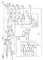
Figure 2 shows an electrical block diagram of a barometric-pressure-sensor device, according to an embodiment of the present invention; and -
Figure 3 shows an example of application of the barometric-pressure-sensor ofFigure 2 in a portable electronic device, in particular a mobile phone. - As will be clarified hereinafter, one aspect of the present invention envisages provision of a pressure sensor of a MEMS type and a corresponding electronic processing circuit, of a purely hardware type, within just one integrated circuit, which performs autonomously, without the aid of external microprocessors, altimeter and altimeter-setting operations.
- In a known way, the "altimeter setting" expression denotes, particularly in the field of aeronautic navigation, the set of operations aimed at setting the altimetric measurement with respect to a given reference. Given that barometric altimeters in general measure a difference of pressure and convert it into a height gain, this setting enables, via setting of the pressure value at the reference altitude, determination of the correct altitude with respect to the reference. Amongst the most widely known altimeter settings are the ones used by pilots and by air-traffic control (ATC), namely:
- "QFE" setting: this is based on the atmospheric pressure measured by a station on the ground (normally an airport) so that a barometric altimeter set on the QFE setting indicates the altitude with respect to a reference airport;
- "QNH" setting: applying this setting, a barometric altimeter indicates (within a certain degree of approximation) a zero altitude at sea level, and consequently indicates, in use, the altitude with respect to the sea level; and
- "standard" setting: the barometric altimeter is set according to the so-called international standard atmosphere (ISA), an ideal atmosphere equal to 1013.25 hPa, the physical characteristics of which have been fixed by the International Civil Aviation Organization (ICAO), the isobar corresponding to this pressure value representing the zero level of flight.
- In detail, and as is illustrated in
Figure 2 , the barometric-pressure-sensor device 20 comprises: apressure sensor 1 of a MEMS type, in particular provided with a microelectromechanical detection structure of the type described with reference toFigure 1 , for measuring the atmospheric pressure; and atemperature sensor 21, for measuring the temperature of the air and of thesame pressure sensor 1. Thetemperature sensor 21 is of an integrated type and made with semiconductor technologies. For example, thetemperature sensor 21 includes a bipolar junction transistor (not illustrated) and is designed to detect the temperature of the air through the variation of a corresponding base-emitter voltage. - The barometric-pressure-
sensor device 20 further comprises: a first logic processing circuit 22 (of a purely hardware type), designed to determine and make available an altitude information; and a second logic processing circuit 23 (of a purely hardware type), designed for carrying out, as will be described in detail hereinafter, functions of altimeter setting, of calculation of derived quantities, and of alarm signalling. - In greater detail, the first
logic processing circuit 22 comprises a first arithmetic-logic unit (ALU) 24 and afirst multiplexer 25. The firstarithmetic unit 24 has a first input and a second input connected, respectively, to thepressure sensor 1 and to thetemperature sensor 21, and an output connected to afirst input 25a of thefirst multiplexer 25. Thefirst multiplexer 25 has asecond input 25b directly connected to the output of thepressure sensor 1, and anoutput 25c, defining a first output of the pressure-sensor device 20. - The first
arithmetic unit 24 is designed to determine the altitude H at which the barometric-pressure-sensor device 20 is located as a function of the barometric pressure detected by thepressure sensor 1 and of the temperature detected by thetemperature sensor 21. In particular, the altitude H can be, for example, calculated by means of the following equation:
where T is the air temperature, R is the perfect-gas constant, M is the molecular weight in grams of the air, g is the acceleration of gravity, and p(0) is the pressure at sea level. - The
output 25c of thefirst multiplexer 25 hence carries information data both on the barometric pressure (directly detected by the pressure sensor 1) and on the altitude at which the barometric-pressure-sensor device 20 is located (detected by the first arithmetic unit 24), and supplies these data, alternatively, to the first output of the device (for example, for subsequent processing by a microprocessor of a portable electronic device incorporating the barometric-pressure-sensor device 20). - The second
logic processing circuit 23 comprises areference stage 26, designed to supply pressure references by means of which the barometric-pressure-sensor device 20 is able to perform the altimeter setting functions. - In detail, the
reference stage 26 comprises: three reference registers 27-29; and asecond multiplexer 30, having three inputs, each connected to a respective one of the three reference registers 27-29, and an output, on which it supplies alternatively (and according to a received control signal-that is not illustrated) the contents of the three reference registers. - In greater detail, the three reference registers 27-29 contain, respectively:
- a first reference value corresponding to a pressure at sea level (QNH setting);
- a second reference value corresponding to the ISA model (standard setting); and
- a third reference value corresponding to a reference pressure which can be set by a user (QFE setting).
- The second
logic processing circuit 23 moreover comprises a second arithmetic unit (ALU) 31, having afirst input 31a connected to theoutput 25c of thefirst multiplexer 25, asecond input 31b connected to the output of thesecond multiplexer 30 of thereference stage 26, and anoutput 31c, which supplies a differential-pressure measurement, given by the difference between the barometric pressure detected by thepressure sensor 1 and the selected reference value. - The second
logic processing circuit 23 moreover comprises ademultiplexer 32, and three output registers 33-35. - The
demultiplexer 32 has one input connected to theoutput 31c of the secondarithmetic unit 31 and hence receiving the differential-pressure measurement, and three outputs, each connected to a respective one of the three output registers 33-35. In addition, thedemultiplexer 32 is operatively coupled to thesecond multiplexer 30, and in particular receives the same control signal (not illustrated). The three output registers 33, 34, 35 consequently store, respectively, a value of absolute pressure with respect to sea level, a value of absolute pressure with respect to the international standard atmosphere, and a value of relative pressure with respect to a reference pressure set by the user. Basically, according to which one of thereference registers arithmetic unit 31 are written, respectively, in theoutput register output registers respective outputs sensor device 20 and enable reading from outside of the data stored therein. - The second
logic processing circuit 23 further comprises acomparator stage 36, which is connected to theoutput 31c of the secondarithmetic unit 31 and is designed to activate alarms S1, S2 indicating that the height/pressure has been exceeded. - In detail, the
comparator stage 36 comprises: afirst comparator 37 and a second comparator 38 (each of which has an inverting input - and a non-inverting input +); aninverter 39 connected to the non-inverting input of thesecond comparator 38; and athreshold register 40 connected to the non-inverting input of thefirst comparator 37 and to an input of theinverter 39. - The outputs of the
comparators output 31c of the second arithmetic unit 31 (in particular, to the non-inverting input of thefirst comparator 37 and to the inverting input of the second comparator 38) and the contents of thethreshold register 40. - The configuration of the
comparator stage 36 makes it possible to distinguish overstepping (positive or negative) of a range of height/pressure having an amplitude equal to the value contained in thethreshold register 40. In detail, if pth is the pressure corresponding to the value contained in thethreshold register 40 and p0 the pressure corresponding to theoutput 31c of the secondarithmetic unit 31, the alarms S1, S2 indicating that the height/pressure has been exceeded are activated in the following way: - S1 is activated if and only if p0 > pth; and
- S2 is activated if and only if p0 < -pth.
- The alarms S1, S2 are available at output from the barometric-pressure-
sensor device 20 and can lead to activation of particular procedures, such as, for example, an interrupt control on the microprocessor of the portable electronic device in which the barometric-pressure-sensor device 20 is integrated. - The second
logic processing circuit 23 comprises a thirdarithmetic unit 41 having afirst input 41a and asecond input 41b, respectively connected to aclock generator 42, and to theoutput 31c of the secondarithmetic unit 31, and anoutput 41c available on the outside of the barometric-pressure-sensor device 20. The thirdarithmetic unit 41 processes the signals at itsinputs output 41c derived quantities of the pressure/altitude such as, for example, a climb or descent speed, or a meteorological tendency, both of which can be obtained through time-derivative operations on the detected or measured pressure/altitude. -
Figure 3 illustrates a non-limiting example of a portableelectronic device 50 provided with the barometric-pressure-sensor device 20. - As illustrated schematically in
Figure 3 , the barometric-pressure-sensor device 20, made in a single integrated circuit (or chip) 20c and enclosed in a single package, includes two dies 20a and 20b made of semiconductor material. Thefirst die 20a integrates thepressure sensor 1, whilst thesecond die 20b integrates thetemperature sensor 21, the first and the secondlogic processing circuit - The portable
electronic device 50, in particular a mobile phone, is further provided with anantenna 51, adedicated microprocessor 52, aradiofrequency circuit 53, and auser interface 54. Thededicated microprocessor 52 has the main task of supervising the transceiving functions specific to the portableelectronic device 50 and is connected to the barometric-pressure-sensor device 20. - In this case, the
dedicated microprocessor 52 only has to read the signals present on theoutputs sensor device 20, and possibly has the task of executing routines for management of the alarms, including, for example, outputting information to theuser interface 54. Conveniently, the alarms S1, S2 are received on respective interrupt inputs of thededicated microprocessor 52 so as to promptly activate the aforesaid alarm-management routine. - The advantages of the barometric-pressure-
sensor device 20 are clear from the foregoing description. - In particular, the barometric-pressure-
sensor device 20 enables reduction of the computational burden of thededicated microprocessor 52 of the corresponding portableelectronic device 50, in so far as all the operations of processing of the pressure and temperature signals, detected, respectively, by thepressure sensor 1 and by thetemperature sensor 21, for determining the altitude and for execution of the altimeter settings, are performed by the firstlogic processing circuit 22 and by the secondlogic processing circuit 23. Consequently, only the task of reading the output signals, and possibly activating routines for management of the alarms S1, S2 indicating that the height/pressure has been exceeded is entrusted to thededicated microprocessor 52. Thededicated microprocessor 52 can query the barometric-pressure-sensor device 20 at pre-set time intervals, or else only when the user wishes to display his altitude. Alternatively, the barometric-pressure-sensor device 20 can be configured so as to re-activate thededicated microprocessor 52 from a stand-by condition by means of the alarms S1, S2 indicating that the height/pressure has been exceeded. In this way, it is possible to reduce the power dissipation of the portable electronic device without, however, forgoing the altimeter function and altimeter-setting function. - In addition, the barometric-pressure-
sensor device 20 enables a considerable degree of integration, given that both the pressure andtemperature sensors logic processing circuits integrated circuit 20c. The absence of long connections between the various components enables electrical signals with limited noise to be obtained. - In addition, integration of the altimeter and altimeter-setting functions within the
integrated circuit 20c enables reduction of the modifications to be made to thededicated microprocessor 52 of the portableelectronic device 50 as compared to the case of a reprogramming of the firmware of the same dedicated microprocessor. - Finally, it is evident that modifications and variations may be made to the barometric-pressure-
sensor device 20 described herein, without thereby departing from the scope of the present invention, as defined by the annexed claims. - The components of the
logic processing circuits arithmetic units - In addition, expressions of a different type, representing an approximation of the real situation, may be used for calculating the altitude H as a function of the atmospheric pressure and temperature.
- A semiconductor memory, for example of a phase-change type, may be included within the
integrated circuit 20c in which the barometric-pressure-sensor device 20 is provided; this memory may store all the data contained in the registers and be able to carry out both read and write operations, as well as management of a table of alarm activation and of barometric pressure variation in time. - Finally, the barometric-pressure-
sensor device 20 can be conveniently used in further portable electronic devices, such as, for example, a free-flight portable system, supplying to a user all the fundamental parameters of flight; a satellite navigator; a wrist watch; a transceiver; a step counter. The barometric-pressure-sensor device 20 may also be provided in fixed detection stations.
Claims (12)
- A barometric-pressure-sensor device (20), in particular for a portable electronic device (50), comprising a pressure sensor (1) for supplying a barometric pressure measurement,
characterized by further comprising a processing circuit (22, 23) coupled to said pressure sensor (1) and configured to supply an altitude measurement as a function of said barometric pressure measurement; said pressure sensor (1) and said processing circuit (22, 23) being integrated in a single integrated circuit (20c). - The device according to claim 1, wherein said processing circuit (22, 23) is a dedicated circuit of a purely hardware type.
- The device according to claim 1 or 2, wherein said pressure sensor (1) is of a MEMS type.
- The device according to any one of the preceding claims, wherein said single integrated circuit (20c) comprises at least a first die (20a) and a second die (20b) made of semiconductor material, said first die (20a) integrating said pressure sensor (1) and said second die (20b) integrating said processing circuit (22, 23).
- The device according to any one of the preceding claims, further comprising a temperature sensor (21), for supplying an air temperature measurement; said processing circuit (22, 23) configured to supply said altitude measurement as a function of said barometric pressure measurement and said air temperature measurement, by means of an exponential function, and said temperature sensor (21) being integrated in said single integrated circuit (20c).
- The device according to any one of the preceding claims, wherein said processing circuit (22, 23) comprises a reference stage (26), designed to enable altimeter setting functions; said reference stage (26) including a plurality of reference registers (27-29) storing respective pressure references, and an arithmetic unit (31) configured to supply a differential-pressure measurement as a function of said barometric pressure measurement and of a reference selected between said pressure references.
- The device according to claim 6, wherein said processing circuit (22, 23) further comprises an alarm stage (36) provided with a comparator circuit (37, 38) and a threshold register (40); said comparator circuit (37, 38) configured to make a comparison between said differential-pressure measurement and a threshold pressure stored in said threshold register (40), and to supply at output at least one alarm signal (S1, S2) if said differential-pressure measurement has a given relation with said threshold pressure.
- The device according to claim 6 or 7, further comprising a temperature sensor (21), for supplying an air temperature measurement; wherein said processing circuit (22, 23) comprises further arithmetic units (24, 41) configured to perform processing operations based on said barometric pressure measurement and air temperature measurement, in particular for the calculation of said altitude measurement, and for time derivation of said differential-pressure measurement and said altitude measurement.
- The device according to any one of claims 6-8, wherein said processing circuit (22, 23) further comprises an output stage (32-35) provided with a plurality of output registers (33-35), which are operatively coupled to said reference registers (27-29) and each one of which supplies a respective differential-pressure measurement referred to a respective one of said pressure references.
- The device according to claim 3, wherein said pressure sensor (1) comprises: a substrate (2) made of semiconductor material having a buried cavity (3); a flexible membrane (4) suspended over said buried cavity (3); and piezoresistive elements (5) diffused in a surface portion of said flexible membrane (4).
- A portable electronic device (50), having a barometric-pressure-sensor device (20) according to any one of the preceding claims; in particular, said portable electronic device (50) being one of: a wrist watch, a mobile phone, a transceiver, a satellite navigator, and a step-counting device.
- The portable electronic device according to claim 11 when dependent on claim 7, further comprising a dedicated microprocessor (52), designed to manage the general operation of said portable electronic device (50), and having at least one interrupt input connected to said barometric-pressure-sensor device (20) and designed to receive said at least one alarm signal (S1, S2).
Priority Applications (3)
| Application Number | Priority Date | Filing Date | Title |
|---|---|---|---|
| EP08425028A EP2083244B1 (en) | 2008-01-22 | 2008-01-22 | Barometric-pressure-sensor device with altimeter function and altimeter-setting function |
| DE602008003659T DE602008003659D1 (en) | 2008-01-22 | 2008-01-22 | Air pressure measuring device with altitude function and Höhenmetereinstellfunktion |
| US12/357,629 US7908921B2 (en) | 2008-01-22 | 2009-01-22 | Barometric-pressure-sensor device with altimeter function and altimeter-setting function |
Applications Claiming Priority (1)
| Application Number | Priority Date | Filing Date | Title |
|---|---|---|---|
| EP08425028A EP2083244B1 (en) | 2008-01-22 | 2008-01-22 | Barometric-pressure-sensor device with altimeter function and altimeter-setting function |
Publications (3)
| Publication Number | Publication Date |
|---|---|
| EP2083244A1 true EP2083244A1 (en) | 2009-07-29 |
| EP2083244A9 EP2083244A9 (en) | 2010-02-17 |
| EP2083244B1 EP2083244B1 (en) | 2010-11-24 |
Family
ID=39575654
Family Applications (1)
| Application Number | Title | Priority Date | Filing Date |
|---|---|---|---|
| EP08425028A Active EP2083244B1 (en) | 2008-01-22 | 2008-01-22 | Barometric-pressure-sensor device with altimeter function and altimeter-setting function |
Country Status (3)
| Country | Link |
|---|---|
| US (1) | US7908921B2 (en) |
| EP (1) | EP2083244B1 (en) |
| DE (1) | DE602008003659D1 (en) |
Cited By (6)
| Publication number | Priority date | Publication date | Assignee | Title |
|---|---|---|---|---|
| WO2012155000A3 (en) * | 2011-05-10 | 2013-06-13 | Qualcomm Incorporated | Apparatus and methods for height determination |
| CN104155034A (en) * | 2014-08-26 | 2014-11-19 | 蒋和平 | Real-time monitoring system and method of regional ground stress |
| FR3012879A1 (en) * | 2013-11-07 | 2015-05-08 | Withings | METHOD OF ESTIMATING DENIVELE CARRIED OUT BY A USER |
| TWI664396B (en) * | 2018-01-02 | 2019-07-01 | 國立高雄科技大學 | Thermal Barometric Altimeter |
| WO2023215647A1 (en) * | 2022-05-03 | 2023-11-09 | Aerobiotix, Llc | System for detecting opening of a door in a pressurized hospital room by analyzing disturbance in the air pressure of the room |
| US11824333B2 (en) | 2016-12-23 | 2023-11-21 | Igus Gmbh | Systems for monitoring the operation of an energy chain |
Families Citing this family (29)
| Publication number | Priority date | Publication date | Assignee | Title |
|---|---|---|---|---|
| FI122514B (en) * | 2008-12-31 | 2012-02-29 | Suunto Oy | Portable electronic pressure measuring device |
| US8442712B2 (en) | 2011-08-31 | 2013-05-14 | Caterpillar Inc. | System and method to thermally protect a transistor in an electric drive vehicle |
| EP2667280A1 (en) * | 2012-05-23 | 2013-11-27 | Nxp B.V. | Device Control System And Method Of Determining Altitude |
| WO2014087598A1 (en) * | 2012-12-04 | 2014-06-12 | 旭化成株式会社 | Barometric altimeter and barometric altimeter adapted to indoor use |
| JP5937758B2 (en) * | 2013-05-31 | 2016-06-22 | 旭化成株式会社 | A device that identifies changes in the vertical direction using barometric pressure measurements. |
| JP6339669B2 (en) | 2013-07-08 | 2018-06-06 | モーション・エンジン・インコーポレーテッド | MEMS device and method of manufacturing |
| US10273147B2 (en) | 2013-07-08 | 2019-04-30 | Motion Engine Inc. | MEMS components and method of wafer-level manufacturing thereof |
| WO2015013828A1 (en) | 2013-08-02 | 2015-02-05 | Motion Engine Inc. | Mems motion sensor and method of manufacturing |
| EP3039436A4 (en) * | 2013-12-31 | 2017-04-19 | Halliburton Energy Services, Inc. | Method for multiplexing wheatstone bridge measurements |
| WO2015103688A1 (en) | 2014-01-09 | 2015-07-16 | Motion Engine Inc. | Integrated mems system |
| US20170030788A1 (en) | 2014-04-10 | 2017-02-02 | Motion Engine Inc. | Mems pressure sensor |
| WO2015184531A1 (en) | 2014-06-02 | 2015-12-10 | Motion Engine Inc. | Multi-mass mems motion sensor |
| WO2016090467A1 (en) | 2014-12-09 | 2016-06-16 | Motion Engine Inc. | 3d mems magnetometer and associated methods |
| CA3220839A1 (en) | 2015-01-15 | 2016-07-21 | Motion Engine Inc. | 3d mems device with hermetic cavity |
| JP2016138778A (en) * | 2015-01-27 | 2016-08-04 | セイコーエプソン株式会社 | Electronic devices, pressure sensors, altimeters, electronic equipment and moving objects |
| US9767625B1 (en) | 2015-04-13 | 2017-09-19 | Allstate Insurance Company | Automatic crash detection |
| US10083551B1 (en) | 2015-04-13 | 2018-09-25 | Allstate Insurance Company | Automatic crash detection |
| US9574964B2 (en) * | 2015-07-07 | 2017-02-21 | Toyota Jidosha Kabushiki Kaisha | Mobile computer atmospheric barometric pressure system |
| WO2017040027A1 (en) * | 2015-09-04 | 2017-03-09 | Nextnav, Llc | Systems and methods for selecting atmospheric data of reference nodes for use in computing the altitude of a receiver |
| US10132706B2 (en) | 2015-09-28 | 2018-11-20 | Apple Inc. | Waterproof barometric sensor in an electronic device |
| US10104223B2 (en) * | 2016-01-11 | 2018-10-16 | Motorola Mobility Llc | Automatically applying modifications to a device in a liquid environment |
| US9940825B2 (en) | 2016-02-12 | 2018-04-10 | Robert Bosch Gmbh | Barometric pressure to reduce security false alarms |
| US10048778B2 (en) | 2016-05-31 | 2018-08-14 | Microsoft Technology Licensing, Llc | Force sensor apparatus |
| US10228781B2 (en) | 2016-05-31 | 2019-03-12 | Microsoft Technology Licensing, Llc | Resistive force sensor |
| US11361380B2 (en) | 2016-09-21 | 2022-06-14 | Allstate Insurance Company | Enhanced image capture and analysis of damaged tangible objects |
| US10902525B2 (en) | 2016-09-21 | 2021-01-26 | Allstate Insurance Company | Enhanced image capture and analysis of damaged tangible objects |
| US10602326B2 (en) | 2017-10-23 | 2020-03-24 | Polaris Wireless, Inc. | Detection of the occurrence of an event, based on barometric pressure measurements |
| US11009376B2 (en) | 2017-10-23 | 2021-05-18 | Polaris Wireless, Inc. | Estimation of the location of a wireless terminal, based on characterizing a pressure wave |
| CN113810881B (en) * | 2020-06-11 | 2026-01-23 | 中兴通讯股份有限公司 | Information interaction method, server, non-OBU vehicle-mounted terminal and storage medium |
Citations (6)
| Publication number | Priority date | Publication date | Assignee | Title |
|---|---|---|---|---|
| EP0345929A1 (en) * | 1988-06-07 | 1989-12-13 | Citizen Watch Co. Ltd. | A device for measuring altitude and barometric pressure |
| EP0996004A2 (en) * | 1998-10-20 | 2000-04-26 | Hermann Finance Corporation Ltd. | Barometrically compensated altimeter, barometer and weather forecasting system |
| US6713828B1 (en) * | 1999-12-17 | 2004-03-30 | Delphi Technologies, Inc. | Monolithic fully-integrated vacuum sealed BiCMOS pressure sensor |
| US6868731B1 (en) * | 2003-11-20 | 2005-03-22 | Honeywell International, Inc. | Digital output MEMS pressure sensor and method |
| EP1577656A1 (en) | 2004-03-19 | 2005-09-21 | STMicroelectronics S.r.l. | Method for manufacturing a semiconductor pressure sensor |
| EP1775259A1 (en) * | 2005-10-14 | 2007-04-18 | STMicroelectronics S.r.l. | Wafer level package for sensor devices |
Family Cites Families (4)
| Publication number | Priority date | Publication date | Assignee | Title |
|---|---|---|---|---|
| US5224059A (en) * | 1988-06-07 | 1993-06-29 | Citizen Watch Co., Ltd. | Device for measuring altitude and barometric pressure |
| US6522298B1 (en) * | 2001-04-12 | 2003-02-18 | Garmin Ltd. | Device and method for calibrating and improving the accuracy of barometric altimeters with GPS-derived altitudes |
| EP1857776B1 (en) * | 2006-05-19 | 2009-12-23 | ETA SA Manufacture Horlogère Suisse | Barometric altimeter with a temperature compensating device |
| US20090156205A1 (en) * | 2007-12-17 | 2009-06-18 | Douglas Neal Rowitch | Method and Apparatus for Establishing a Wireless Network Signal Acquisition Rate |
-
2008
- 2008-01-22 DE DE602008003659T patent/DE602008003659D1/en active Active
- 2008-01-22 EP EP08425028A patent/EP2083244B1/en active Active
-
2009
- 2009-01-22 US US12/357,629 patent/US7908921B2/en active Active
Patent Citations (6)
| Publication number | Priority date | Publication date | Assignee | Title |
|---|---|---|---|---|
| EP0345929A1 (en) * | 1988-06-07 | 1989-12-13 | Citizen Watch Co. Ltd. | A device for measuring altitude and barometric pressure |
| EP0996004A2 (en) * | 1998-10-20 | 2000-04-26 | Hermann Finance Corporation Ltd. | Barometrically compensated altimeter, barometer and weather forecasting system |
| US6713828B1 (en) * | 1999-12-17 | 2004-03-30 | Delphi Technologies, Inc. | Monolithic fully-integrated vacuum sealed BiCMOS pressure sensor |
| US6868731B1 (en) * | 2003-11-20 | 2005-03-22 | Honeywell International, Inc. | Digital output MEMS pressure sensor and method |
| EP1577656A1 (en) | 2004-03-19 | 2005-09-21 | STMicroelectronics S.r.l. | Method for manufacturing a semiconductor pressure sensor |
| EP1775259A1 (en) * | 2005-10-14 | 2007-04-18 | STMicroelectronics S.r.l. | Wafer level package for sensor devices |
Non-Patent Citations (2)
| Title |
|---|
| R. COLIN JOHNSON: "MEMS devices go multidice, get smarter", EE TIMES, 16 April 2007 (2007-04-16), http://www.eetimes.com/showArticle.jhtml?articleID=199000278, XP002491401 * |
| RICK RUSSELL, ULF MERIHEINA: "Absolute Pressure Measurement using 3D-MEMS Technology", NANOTECH 2005, vol. 2, May 2005 (2005-05-01), pages 511 - 514, XP002491402 * |
Cited By (8)
| Publication number | Priority date | Publication date | Assignee | Title |
|---|---|---|---|---|
| WO2012155000A3 (en) * | 2011-05-10 | 2013-06-13 | Qualcomm Incorporated | Apparatus and methods for height determination |
| FR3012879A1 (en) * | 2013-11-07 | 2015-05-08 | Withings | METHOD OF ESTIMATING DENIVELE CARRIED OUT BY A USER |
| EP2870911A1 (en) * | 2013-11-07 | 2015-05-13 | Withings | Method for estimating the elevation travelled by a user |
| US9989360B2 (en) | 2013-11-07 | 2018-06-05 | Withings | Method for estimating elevation changes traveled by a user |
| CN104155034A (en) * | 2014-08-26 | 2014-11-19 | 蒋和平 | Real-time monitoring system and method of regional ground stress |
| US11824333B2 (en) | 2016-12-23 | 2023-11-21 | Igus Gmbh | Systems for monitoring the operation of an energy chain |
| TWI664396B (en) * | 2018-01-02 | 2019-07-01 | 國立高雄科技大學 | Thermal Barometric Altimeter |
| WO2023215647A1 (en) * | 2022-05-03 | 2023-11-09 | Aerobiotix, Llc | System for detecting opening of a door in a pressurized hospital room by analyzing disturbance in the air pressure of the room |
Also Published As
| Publication number | Publication date |
|---|---|
| US7908921B2 (en) | 2011-03-22 |
| EP2083244B1 (en) | 2010-11-24 |
| DE602008003659D1 (en) | 2011-01-05 |
| US20090217754A1 (en) | 2009-09-03 |
| EP2083244A9 (en) | 2010-02-17 |
Similar Documents
| Publication | Publication Date | Title |
|---|---|---|
| EP2083244B1 (en) | Barometric-pressure-sensor device with altimeter function and altimeter-setting function | |
| Lammel | The future of MEMS sensors in our connected world | |
| US9273967B2 (en) | Bias estimating method, posture estimating method, bias estimating device, and posture estimating device | |
| EP1847807B1 (en) | Motion classification methods for personal navigation | |
| US8718963B2 (en) | System and method for calibrating a three-axis accelerometer | |
| TWI417523B (en) | Network element, computer program product and method, computer program, mobile terminal and system for determining the altitude of a mobile terminal | |
| RU2018141125A (en) | METHODS AND SYSTEMS FOR DETERMINING THE AIR SPEED OF Aircraft | |
| US20130204567A1 (en) | Method and arrangement for determining altitude | |
| JP4952619B2 (en) | POSITIONING METHOD, PROGRAM, AND POSITIONING DEVICE | |
| CN104169680A (en) | Monitoring the change in height of a device using an air pressure sensor | |
| RU2406973C2 (en) | Method for calibration of platform-free inertial navigation systems | |
| US9360560B2 (en) | Performing GPS operations in receiver sensor engine and position engine | |
| GB2465043A (en) | Systems and methods for tracking a moving person including determining a body offset angle based on spectral analysis of acceleration data | |
| JP2010531974A (en) | Weather forecasting system | |
| WO2008068542A1 (en) | Auto-calibration method for sensors and auto-calibrating sensor arrangement | |
| US5191792A (en) | Instrument for indicating altitude or direction | |
| JP2884502B2 (en) | Wide-velocity range flight velocity vector measurement system using quadrangular pyramid-shaped 5-hole probe | |
| JP7760880B2 (en) | Inertial Sensor Module | |
| KR20120121595A (en) | Position calculation apparatus and method that use acceleration sensor | |
| US8510079B2 (en) | Systems and methods for an advanced pedometer | |
| EP3785049B1 (en) | Method for calibrating sensor or azimuth information obtained through sensor, based on azimuth information obtained using satellite positioning circuit, and electronic device supporting the same | |
| RU2539140C1 (en) | Integrated strapdown system of navigation of average accuracy for unmanned aerial vehicle | |
| US7324002B2 (en) | Outdoor computer | |
| US20100261984A1 (en) | Physiology sensing apparatus with navigation capability | |
| US11556185B1 (en) | System to detect user input using a pressure sensor |
Legal Events
| Date | Code | Title | Description |
|---|---|---|---|
| PUAI | Public reference made under article 153(3) epc to a published international application that has entered the european phase |
Free format text: ORIGINAL CODE: 0009012 |
|
| AK | Designated contracting states |
Kind code of ref document: A1 Designated state(s): AT BE BG CH CY CZ DE DK EE ES FI FR GB GR HR HU IE IS IT LI LT LU LV MC MT NL NO PL PT RO SE SI SK TR |
|
| AX | Request for extension of the european patent |
Extension state: AL BA MK RS |
|
| RTI1 | Title (correction) |
Free format text: BAROMETRIC-PRESSURE-SENSOR DEVICE WITH ALTIMETER FUNCTION AND ALTIMETER-SETTING FUNCTION |
|
| 17P | Request for examination filed |
Effective date: 20100121 |
|
| AKX | Designation fees paid |
Designated state(s): DE FR GB IT |
|
| RAP1 | Party data changed (applicant data changed or rights of an application transferred) |
Owner name: STMICROELECTRONICS SRL |
|
| GRAP | Despatch of communication of intention to grant a patent |
Free format text: ORIGINAL CODE: EPIDOSNIGR1 |
|
| GRAS | Grant fee paid |
Free format text: ORIGINAL CODE: EPIDOSNIGR3 |
|
| GRAA | (expected) grant |
Free format text: ORIGINAL CODE: 0009210 |
|
| AK | Designated contracting states |
Kind code of ref document: B1 Designated state(s): DE FR GB IT |
|
| REG | Reference to a national code |
Ref country code: GB Ref legal event code: FG4D |
|
| REF | Corresponds to: |
Ref document number: 602008003659 Country of ref document: DE Date of ref document: 20110105 Kind code of ref document: P |
|
| PLBE | No opposition filed within time limit |
Free format text: ORIGINAL CODE: 0009261 |
|
| STAA | Information on the status of an ep patent application or granted ep patent |
Free format text: STATUS: NO OPPOSITION FILED WITHIN TIME LIMIT |
|
| 26N | No opposition filed |
Effective date: 20110825 |
|
| REG | Reference to a national code |
Ref country code: DE Ref legal event code: R097 Ref document number: 602008003659 Country of ref document: DE Effective date: 20110825 |
|
| GBPC | Gb: european patent ceased through non-payment of renewal fee |
Effective date: 20120122 |
|
| PG25 | Lapsed in a contracting state [announced via postgrant information from national office to epo] |
Ref country code: GB Free format text: LAPSE BECAUSE OF NON-PAYMENT OF DUE FEES Effective date: 20120122 |
|
| PGFP | Annual fee paid to national office [announced via postgrant information from national office to epo] |
Ref country code: FR Payment date: 20140120 Year of fee payment: 7 Ref country code: IT Payment date: 20131219 Year of fee payment: 7 |
|
| REG | Reference to a national code |
Ref country code: FR Ref legal event code: ST Effective date: 20150930 |
|
| PG25 | Lapsed in a contracting state [announced via postgrant information from national office to epo] |
Ref country code: FR Free format text: LAPSE BECAUSE OF NON-PAYMENT OF DUE FEES Effective date: 20150202 |
|
| PG25 | Lapsed in a contracting state [announced via postgrant information from national office to epo] |
Ref country code: IT Free format text: LAPSE BECAUSE OF NON-PAYMENT OF DUE FEES Effective date: 20150122 |
|
| PGFP | Annual fee paid to national office [announced via postgrant information from national office to epo] |
Ref country code: DE Payment date: 20251217 Year of fee payment: 19 |