EP2083171A1 - Fluid handling apparatus - Google Patents
Fluid handling apparatus Download PDFInfo
- Publication number
- EP2083171A1 EP2083171A1 EP08425036A EP08425036A EP2083171A1 EP 2083171 A1 EP2083171 A1 EP 2083171A1 EP 08425036 A EP08425036 A EP 08425036A EP 08425036 A EP08425036 A EP 08425036A EP 2083171 A1 EP2083171 A1 EP 2083171A1
- Authority
- EP
- European Patent Office
- Prior art keywords
- worm screw
- external guide
- fluid handling
- piston
- rotor
- Prior art date
- Legal status (The legal status is an assumption and is not a legal conclusion. Google has not performed a legal analysis and makes no representation as to the accuracy of the status listed.)
- Withdrawn
Links
- 239000012530 fluid Substances 0.000 title claims abstract description 37
- 238000012546 transfer Methods 0.000 claims abstract description 16
- 238000000034 method Methods 0.000 claims description 3
- 230000004913 activation Effects 0.000 claims 1
- 230000003993 interaction Effects 0.000 claims 1
- 230000007246 mechanism Effects 0.000 description 7
- 230000001133 acceleration Effects 0.000 description 6
- 238000001816 cooling Methods 0.000 description 3
- 238000005461 lubrication Methods 0.000 description 3
- 238000012423 maintenance Methods 0.000 description 3
- 238000013519 translation Methods 0.000 description 3
- 230000000694 effects Effects 0.000 description 2
- 239000007788 liquid Substances 0.000 description 2
- 238000004804 winding Methods 0.000 description 2
- 239000003638 chemical reducing agent Substances 0.000 description 1
- 238000004891 communication Methods 0.000 description 1
- 230000003247 decreasing effect Effects 0.000 description 1
- 230000001419 dependent effect Effects 0.000 description 1
- 230000005684 electric field Effects 0.000 description 1
- 230000002349 favourable effect Effects 0.000 description 1
- 229930195733 hydrocarbon Natural products 0.000 description 1
- 150000002430 hydrocarbons Chemical class 0.000 description 1
- 230000002452 interceptive effect Effects 0.000 description 1
- 230000001050 lubricating effect Effects 0.000 description 1
- 239000012528 membrane Substances 0.000 description 1
- 239000003921 oil Substances 0.000 description 1
- 239000003208 petroleum Substances 0.000 description 1
- 230000010349 pulsation Effects 0.000 description 1
- 230000003134 recirculating effect Effects 0.000 description 1
- 238000005096 rolling process Methods 0.000 description 1
Images


Classifications
-
- F—MECHANICAL ENGINEERING; LIGHTING; HEATING; WEAPONS; BLASTING
- F04—POSITIVE - DISPLACEMENT MACHINES FOR LIQUIDS; PUMPS FOR LIQUIDS OR ELASTIC FLUIDS
- F04B—POSITIVE-DISPLACEMENT MACHINES FOR LIQUIDS; PUMPS
- F04B17/00—Pumps characterised by combination with, or adaptation to, specific driving engines or motors
- F04B17/03—Pumps characterised by combination with, or adaptation to, specific driving engines or motors driven by electric motors
-
- F—MECHANICAL ENGINEERING; LIGHTING; HEATING; WEAPONS; BLASTING
- F04—POSITIVE - DISPLACEMENT MACHINES FOR LIQUIDS; PUMPS FOR LIQUIDS OR ELASTIC FLUIDS
- F04B—POSITIVE-DISPLACEMENT MACHINES FOR LIQUIDS; PUMPS
- F04B11/00—Equalisation of pulses, e.g. by use of air vessels; Counteracting cavitation
- F04B11/005—Equalisation of pulses, e.g. by use of air vessels; Counteracting cavitation using two or more pumping pistons
- F04B11/0058—Equalisation of pulses, e.g. by use of air vessels; Counteracting cavitation using two or more pumping pistons with piston speed control
-
- F—MECHANICAL ENGINEERING; LIGHTING; HEATING; WEAPONS; BLASTING
- F04—POSITIVE - DISPLACEMENT MACHINES FOR LIQUIDS; PUMPS FOR LIQUIDS OR ELASTIC FLUIDS
- F04B—POSITIVE-DISPLACEMENT MACHINES FOR LIQUIDS; PUMPS
- F04B9/00—Piston machines or pumps characterised by the driving or driven means to or from their working members
- F04B9/02—Piston machines or pumps characterised by the driving or driven means to or from their working members the means being mechanical
Definitions
- the present invention relates to a fluid handling apparatus, in particular to a piston pump of the type specified in the preamble of Claim 1.
- the most common reciprocating pumps act by means of at least a piston that moves with reciprocating motion inside a cylindrical chamber.
- the cylindrical chamber is also in communication with two one-way valves and in particular a suction valve and a discharge valve.
- Said piston determines a continuous and alternating variation of the volume inside the cylindrical chamber. Consequently, during increase of the volume of the chamber, fluid enters this chamber through the suction valve and, during decrease of the volume of the chamber, fluid exits therefrom through the discharge valve.
- crank-connecting rod mechanism The reciprocating movement of the piston is generally activated by means of known crank-connecting rod mechanism.
- Said piston is therefore normally connected to a crank substantially realized by a circular wheel that moves appropriately with a constant rotation speed.
- crank is then connected to a rotary electric motor and to appropriate mechanical connections, realized by speed reduction gears, drive belts and the like.
- Said reciprocating pumps also comprise a lubrication system for the mechanical connections and for the crank mechanism described and a cooling system for these and for the electric motor.
- crank mechanism described activates the piston with speeds and accelerations determined by the angular position of the crank, or wheel.
- this connecting rod is substantially stopped for an instant, while when the crank is substantially perpendicular to the direction of motion of the connecting rod, the latter moves at maximum speed.
- the connecting rod therefore moves with a sinusoidally varying speed.
- the speed variation of the connecting rod, or of the piston therefore determines a variation of the transfer speed of fluids, or flow rate, which also occurs according to a sinusoidal curve.
- Said continuous variation of the flow rate causes troublesome pressure pulsations inside the hydraulic pump, which have a negative effect in particular on the ducts that transfer the fluids and consequently on the entire system.
- cranks realized by a non circular cam or the like are also possible, such as the use of cranks realized by a non circular cam or the like.
- the technical aim underlying the present invention is to devise a fluid handling apparatus capable of substantially overcoming the aforesaid drawbacks.
- an important object of the invention is to provide a fluid handling apparatus that allows the vibrations and noise of this apparatus to be decreased considerably.
- Another important object of the invention is to obtain a fluid handling apparatus that is simple, inexpensive and requires little maintenance.
- Last but not least object of the invention is to provide a fluid handling apparatus that is compact and occupies a small space.
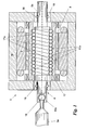
- the apparatus 1 comprises at least a fluid handling device 2, comprising, briefly, at least a piston 3 movable with reciprocating translational motion, preferably of the plunging type, and suitable to vary the volume of a transfer chamber 4 that allows the handling of fluids, and movement members 5 of the piston 3 suitable to generate the reciprocating translational motion.
- the transfer chamber 4 is preferably realized by a cylinder 11 inside which the piston 3 moves with reciprocating translational, and preferably rectilinear, motion.
- This transfer chamber 4 is also in fluid connection with a suction channel 12 through an inlet valve 13, realized by a one-way valve suitable to allow fluid to enter the transfer chamber 4, and with a discharge channel 14 through a discharge valve 15, realized by a one-way valve suitable to allow fluid to exit from the transfer chamber 4.
- the transfer chamber 4 can be connected to the piston 3 by means of a membrane or can be of a different type.
- the piston 3 is then mechanically connected to a drive shaft 3a, in turn connected to the movement members 5 preferably by means of a ball joint 16 suitable to substantially cancel the undesirable effects caused by any misalignment between the movement members 5 and the drive shaft 3a.
- the piston 3 is directly an integral part of the drive shaft 3a.
- the movement members 5 comprise a worm screw 6, movable about an axis 6a and an external guide 7 for this worm screw 6, substantially coaxial therewith.
- the external guide 7 is therefore rotatable about the axis 6a and this rotational movement activates translation, substantially without rotation, of the worm screw 6 in a direction parallel to this axis 6a.
- the worm screw 6 is associated with a helicoid 17, which substantially realizes the thread of the worm screw 6, and this worm screw is preferably directly in contact with the external guide 7.
- This helicoid 17 is also preferably realized by a plurality of balls 17a suitable to roll along helical guides 17b produced on the external surface of the worm screw 6 and of the external guide 7, as shown in Fig. 1 .
- the external guide 7 is also provided with a recirculation channel for said balls, not shown in the accompanying figures, joining the opposite ends of the helicoid 17.
- the worm screw 6 including in particular the helicoid 17, and also said recirculating ball screw, allows helical movements to be performed with extremely low friction due to the presence of spherical elements that move through rolling friction.
- the worm screw 6 is also preferably connected directly to the drive shaft 3a and for this purpose comprises a spherical seat 16a for the ball joint 16. Moreover, each worm screw 6 can be connected to two pistons 3 and comprise a seat at each end, as shown in Fig. 3 .
- the worm screw 6 comprises at least a sliding block 18 suitable to allow translation in a direction parallel to the axis 6a and to prevent rotation of the worm screw 6 about this axis 6a.
- the movement members 5 also comprise an electric motor 8 including a stator 9 and a rotor 10, integral with the external guide 7.
- the rotor 10 is substantially integrated with the external guide 7 and is therefore coaxial with the axis 6a.
- this rotor 10 is preferably realized by permanent magnets appropriately shaped as portions of cylindrical surface. This solution allows friction to be reduced, as no electrical connections are required between the rotor and the outside.
- the stator 9 is instead appropriately realized by electrical windings connected to an alternating current power supply. It is preferably disposed on the outside of the rotor 10 and has a cylindrical shape coaxial therewith, as shown in Fig. 1 . In detail, the stator 9 is appropriately connected to an inverter, known per se, connected to a power supply network.
- Said inverter is suitable to allow variations of the power and of the frequency of the alternating current that supplies the electric motor 8. It is also connected to specific control means preferably realized by an electronic processor.
- the device 2 is preferably supported by a single structure 19 suitable to support the various elements described, and in particular the transfer chamber 4, the piston 3, the connections of the suction 12 and discharge 14 channels including the specific valves 13 and 15 and the movement members 5.
- the structure 19 is also suitable to contain any leakages of fluids, so that they are not dispersed dangerously into the outside environment.
- the device 2 can also comprise a lubrication system suitable to allow improved sliding of the worm screw 6 and of the other mechanical members.
- a single fluid handling apparatus 1 also preferably comprises a plurality of fluid handling devices 2.
- fluid handling devices 2 are preferably present, disposed in parallel as shown in Fig. 3 and all connected to unitary control means realized by a single electronic processor.
- Movement of the pistons 3 belonging to a single apparatus 1 also occurs according to a new process.
- said new process consists in moving the pistons 3 so that the suction volumetric flow rate and the discharge volumetric of the fluid are substantially constant.
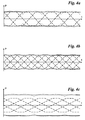
- volumetric flow rates of apparatuses 1 are shown in Figs. 4a, 4b and 4c . These figures show the volumetric flow rates of apparatuses 1 including three, four or five devices 2.
- dashed lines represent the volumetric flow rates of each piston 3, while the solid lines represent the total suction and discharge volumetric flow rates of the apparatus 1.
- the total discharge volumetric flow rate is attained by adding the positive flow rates, while the total suction volumetric flow rate is attained by adding the negative flow rates.
- the pistons 3 move with non-null constant accelerations (inclined straight segments) in particular in proximity of the ends of stroke (corresponding to the points of the graph along the axis of the abscissae) or with constant and null accelerations and therefore constant speeds (straight segments parallel to the axis of the abscissae) in particular at a distance from the ends of stroke.
- the rotor 10 is integral with the external guide 7, which by rotating activates translation of the worm screw 6.
- the worm screw 6 in turn activates the reciprocating translational motion of one or two pistons 3, which by varying the volume of the transfer chamber 4, allow the transfer of fluids, and in particular of liquids, from the suction channel 12 to the discharge channel 14.
- the speed and direction of rotation are selected by means of the inverter and of the control means. It is therefore possible to easily select all the movement parameters of the apparatus 1 and in particular of the pistons 3: the stroke, speed and acceleration of the worm screws 6, thus promptly and precisely controlling each parameter of the apparatus.
- each device 2 The flow rates of each device 2 are therefore preferably selected according to the curves indicated in Figs. 4a, 4b and 4c .
- the invention achieves important advantages.
- the apparatus 1 allows a flow rate of fluid that is always constant to be produced and does not cause noise, vibrations or similar drawbacks.
- the apparatus 1 therefore requires less maintenance than apparatuses according to prior art.
- this apparatus 1 is very compact and less bulky, as the crank mechanism, the speed reducer, the dampers, several joints, the motor and various gaskets are eliminated and moreover the lubrication and cooling devices are greatly reduced, or even completely eliminated.
Landscapes
- Engineering & Computer Science (AREA)
- Mechanical Engineering (AREA)
- General Engineering & Computer Science (AREA)
- Reciprocating Pumps (AREA)
- Transmission Devices (AREA)
Abstract
Description
- The present invention relates to a fluid handling apparatus, in particular to a piston pump of the type specified in the preamble of Claim 1.
- There are currently known reciprocating pumps for transferring fluids, in particular oils, petroleum and the like.
- The most common reciprocating pumps act by means of at least a piston that moves with reciprocating motion inside a cylindrical chamber.
- The cylindrical chamber is also in communication with two one-way valves and in particular a suction valve and a discharge valve.
- Said piston determines a continuous and alternating variation of the volume inside the cylindrical chamber. Consequently, during increase of the volume of the chamber, fluid enters this chamber through the suction valve and, during decrease of the volume of the chamber, fluid exits therefrom through the discharge valve.
- The reciprocating movement of the piston is generally activated by means of known crank-connecting rod mechanism.
- Said piston is therefore normally connected to a crank substantially realized by a circular wheel that moves appropriately with a constant rotation speed.
- The crank is then connected to a rotary electric motor and to appropriate mechanical connections, realized by speed reduction gears, drive belts and the like.
- Said reciprocating pumps also comprise a lubrication system for the mechanical connections and for the crank mechanism described and a cooling system for these and for the electric motor.
- The aforesaid prior art has some important drawbacks.
- In fact, the crank mechanism described activates the piston with speeds and accelerations determined by the angular position of the crank, or wheel. In particular, when the crank is substantially parallel to the direction of movement of the connecting rod, this connecting rod is substantially stopped for an instant, while when the crank is substantially perpendicular to the direction of motion of the connecting rod, the latter moves at maximum speed.
- The connecting rod therefore moves with a sinusoidally varying speed.
- The speed variation of the connecting rod, or of the piston, therefore determines a variation of the transfer speed of fluids, or flow rate, which also occurs according to a sinusoidal curve.
- Said continuous variation of the flow rate causes troublesome pressure pulsations inside the hydraulic pump, which have a negative effect in particular on the ducts that transfer the fluids and consequently on the entire system.
- These vibrations can lead to undesirable noise, and above all to fatigue stresses that can determine the breakage of some portions of the pumps or of the ducts, loosening of screws and bolts present on these pumps or ducts and yet other drawbacks.
- Said drawbacks can only be partly solved by the use of reciprocating pumps utilizing several pistons simultaneously and moving these pistons by means of crank mechanisms having specific reciprocal angular phase differences, so that, when one piston is substantially stopped, the other moves at maximum speed and vice versa.
- Other measures are also possible, such as the use of cranks realized by a non circular cam or the like.
- However, these solutions can never completely eliminate said variations of the fluid transfer speed and moreover they form a further complication and make the structure of the hydraulic pump heavier.
- A further drawback is realized by the fact that said reciprocating pumps, due to their complex crank mechanism and to the presence of various components, are very expensive, must be produced with reduced tolerances, require a specific lubricating and cooling apparatus and therefore continuous and costly maintenance.
- Yet another drawback is realized by the fact that reciprocating pumps, and the apparatuses connected thereto, are very bulky and therefore large spaces are required to house them.
- In this situation the technical aim underlying the present invention is to devise a fluid handling apparatus capable of substantially overcoming the aforesaid drawbacks.
- Within the scope of said technical aim, an important object of the invention is to provide a fluid handling apparatus that allows the vibrations and noise of this apparatus to be decreased considerably.
- Another important object of the invention is to obtain a fluid handling apparatus that is simple, inexpensive and requires little maintenance.
- Last but not least object of the invention is to provide a fluid handling apparatus that is compact and occupies a small space.
- The technical aim and the objects specified are achieved by a fluid handling apparatus as claimed in the appended Claim 1.
- Preferred embodiments are highlighted in the dependent claims.
- Other characteristics and advantages of the invention are further elucidated in the following detailed description of a preferred embodiment of the invention, with reference to the accompanying drawings, wherein:
-
Fig. 1 shows a section of a portion of the apparatus according to the invention; -
Fig. 2 shows a further section of the apparatus according to the invention; -
Fig. 3 shows an assembly view, in a particular configuration, of the apparatus according to the invention; -
Fig. 4a shows a first graph of operation of the apparatus according to the invention; -
Fig. 4b shows a second graph of operation of the apparatus according to the invention; -
Fig. 4c shows a third graph of operation of the apparatus according to the invention. - With reference to the figures above, the fluid handling apparatus according to the invention is indicated as a whole with the number 1.
- It is suitable to handle fluids, in particular liquids and more in particular hydrocarbons and their derivatives.
- The apparatus 1 comprises at least a
fluid handling device 2, comprising, briefly, at least apiston 3 movable with reciprocating translational motion, preferably of the plunging type, and suitable to vary the volume of a transfer chamber 4 that allows the handling of fluids, andmovement members 5 of thepiston 3 suitable to generate the reciprocating translational motion. - In more detail, the transfer chamber 4 is preferably realized by a
cylinder 11 inside which thepiston 3 moves with reciprocating translational, and preferably rectilinear, motion. - This transfer chamber 4 is also in fluid connection with a
suction channel 12 through aninlet valve 13, realized by a one-way valve suitable to allow fluid to enter the transfer chamber 4, and with adischarge channel 14 through adischarge valve 15, realized by a one-way valve suitable to allow fluid to exit from the transfer chamber 4. - Alternatively, the transfer chamber 4 can be connected to the
piston 3 by means of a membrane or can be of a different type. - The
piston 3 is then mechanically connected to adrive shaft 3a, in turn connected to themovement members 5 preferably by means of aball joint 16 suitable to substantially cancel the undesirable effects caused by any misalignment between themovement members 5 and thedrive shaft 3a. Alternatively, thepiston 3 is directly an integral part of thedrive shaft 3a. - The
movement members 5 comprise aworm screw 6, movable about anaxis 6a and an external guide 7 for thisworm screw 6, substantially coaxial therewith. - The external guide 7 is therefore rotatable about the
axis 6a and this rotational movement activates translation, substantially without rotation, of theworm screw 6 in a direction parallel to thisaxis 6a. - In detail, the
worm screw 6 is associated with ahelicoid 17, which substantially realizes the thread of theworm screw 6, and this worm screw is preferably directly in contact with the external guide 7. Thishelicoid 17 is also preferably realized by a plurality ofballs 17a suitable to roll along helical guides 17b produced on the external surface of theworm screw 6 and of the external guide 7, as shown inFig. 1 . - The external guide 7 is also provided with a recirculation channel for said balls, not shown in the accompanying figures, joining the opposite ends of the
helicoid 17. - It is therefore suitable to recirculate the
balls 17a, which due to their motion move to the outside of one of the ends of the helical guides 17b, to return to the helical guides 17b at the opposite end. - The
worm screw 6 including in particular thehelicoid 17, and also said recirculating ball screw, allows helical movements to be performed with extremely low friction due to the presence of spherical elements that move through rolling friction. - The
worm screw 6 is also preferably connected directly to thedrive shaft 3a and for this purpose comprises aspherical seat 16a for theball joint 16. Moreover, eachworm screw 6 can be connected to twopistons 3 and comprise a seat at each end, as shown inFig. 3 . - Finally, the
worm screw 6 comprises at least a slidingblock 18 suitable to allow translation in a direction parallel to theaxis 6a and to prevent rotation of theworm screw 6 about thisaxis 6a. - The
movement members 5 also comprise anelectric motor 8 including astator 9 and a rotor 10, integral with the external guide 7. - In particular, the rotor 10 is substantially integrated with the external guide 7 and is therefore coaxial with the
axis 6a. - Moreover, this rotor 10 is preferably realized by permanent magnets appropriately shaped as portions of cylindrical surface. This solution allows friction to be reduced, as no electrical connections are required between the rotor and the outside.
- The
stator 9 is instead appropriately realized by electrical windings connected to an alternating current power supply. It is preferably disposed on the outside of the rotor 10 and has a cylindrical shape coaxial therewith, as shown inFig. 1 . In detail, thestator 9 is appropriately connected to an inverter, known per se, connected to a power supply network. - Said inverter is suitable to allow variations of the power and of the frequency of the alternating current that supplies the
electric motor 8. It is also connected to specific control means preferably realized by an electronic processor. - Structurally, the
device 2 is preferably supported by asingle structure 19 suitable to support the various elements described, and in particular the transfer chamber 4, thepiston 3, the connections of thesuction 12 anddischarge 14 channels including thespecific valves movement members 5. - It is shown in particular in
Fig. 2 . - The
structure 19 is also suitable to contain any leakages of fluids, so that they are not dispersed dangerously into the outside environment. - The
device 2 can also comprise a lubrication system suitable to allow improved sliding of theworm screw 6 and of the other mechanical members. - A single fluid handling apparatus 1 also preferably comprises a plurality of
fluid handling devices 2. - In particular, between two and ten, and more preferably three, four or five
fluid handling devices 2 are preferably present, disposed in parallel as shown inFig. 3 and all connected to unitary control means realized by a single electronic processor. - Movement of the
pistons 3 belonging to a single apparatus 1 also occurs according to a new process. - In fact, said new process consists in moving the
pistons 3 so that the suction volumetric flow rate and the discharge volumetric of the fluid are substantially constant. - Some examples of volumetric flow rates of apparatuses 1 according to the invention are shown in
Figs. 4a, 4b and 4c . These figures show the volumetric flow rates of apparatuses 1 including three, four or fivedevices 2. - These flow rates are related with the volumetric flow rates of apparatuses according to prior art (dotted line) comprising three, four or five pistons moved by means of a crank-connecting rod mechanism.
- These graphs show on the abscissa the volumetric flow rate, directly proportional to the movement speed of the
pistons 3, as a function of the time indicated on the ordinate. - In more detail, the dashed lines represent the volumetric flow rates of each
piston 3, while the solid lines represent the total suction and discharge volumetric flow rates of the apparatus 1. - In particular, the total discharge volumetric flow rate is attained by adding the positive flow rates, while the total suction volumetric flow rate is attained by adding the negative flow rates.
- As can be observed in said figures, the
pistons 3 move with non-null constant accelerations (inclined straight segments) in particular in proximity of the ends of stroke (corresponding to the points of the graph along the axis of the abscissae) or with constant and null accelerations and therefore constant speeds (straight segments parallel to the axis of the abscissae) in particular at a distance from the ends of stroke. - In more detail, if an even number of
pistons 3 is present (Fig. 5a) it is possible always to have constant and non-null accelerations and decelerations, while if an odd number of pistons is present (Figs. 4a and 6a) it is also favourable to have sections with null constant accelerations. - Operation of a fluid transfer apparatus 1, described above in structural terms, is the following.
- When it is activated, an electrical current passes through the electrical windings of the
stator 9, creating a magnetic field which, interfering with the electrical field of the permanent magnets of the rotor 10, allows rotation thereof. - The rotor 10 is integral with the external guide 7, which by rotating activates translation of the
worm screw 6. - The
worm screw 6 in turn activates the reciprocating translational motion of one or twopistons 3, which by varying the volume of the transfer chamber 4, allow the transfer of fluids, and in particular of liquids, from thesuction channel 12 to thedischarge channel 14. - The speed and direction of rotation are selected by means of the inverter and of the control means. It is therefore possible to easily select all the movement parameters of the apparatus 1 and in particular of the pistons 3: the stroke, speed and acceleration of the worm screws 6, thus promptly and precisely controlling each parameter of the apparatus.
- The flow rates of each
device 2 are therefore preferably selected according to the curves indicated inFigs. 4a, 4b and 4c . - The invention achieves important advantages.
- In fact, the apparatus 1 allows a flow rate of fluid that is always constant to be produced and does not cause noise, vibrations or similar drawbacks.
- The apparatus 1 therefore requires less maintenance than apparatuses according to prior art.
- Moreover, due to its structure, this apparatus 1 is very compact and less bulky, as the crank mechanism, the speed reducer, the dampers, several joints, the motor and various gaskets are eliminated and moreover the lubrication and cooling devices are greatly reduced, or even completely eliminated.
- Finally, as it has no structurally complex elements, it is simple and inexpensive.
Claims (10)
- Fluid handling apparatus (1) including at least a fluid handling device (2) comprising: at least a piston (3) movable with reciprocating translational motion and suitable to vary the volume of a transfer chamber (4) and to allow said handling of fluids, and movement members (5) of said at least a piston (3) suitable to impart said reciprocating translational motion on said piston (3), characterized in that said movement members (5) comprise: a worm screw (6) having an axis (6a), an external guide (7) for said worm screw (6), substantially coaxial with said worm screw (6) and suitable to take a rotational motion about said axis (6a), and an electric motor (8) comprising a stator (9) and a rotor (10), said rotor (10) being integral with said external guide (7) and said worm screw (6) being suitable to transform said rotational motion of said external guide (7) into translational motion.
- Apparatus according to claim 1, wherein said worm screw (6) is associated with a helicoid (17), directly in contact with said external guide (7).
- Apparatus according to claim 2, wherein said helicoid (17) is realized by a plurality of balls (17a) and wherein said worm screw (6) and said external guide (7) define helical guides (17b) in the area of interaction with said helicoid (17) suitable to house said balls (17a).
- Apparatus according to claim 3, wherein said external guide (7) comprises a recirculation channel for said balls (17a), joining the opposite ends of said helicoid (17).
- Apparatus according to one or more of the preceding claims, wherein said rotor (10) is substantially integrated with said external guide (7).
- Apparatus according to one or more of the preceding claims, wherein said rotor (10) is realized by permanent magnets.
- Apparatus according to one or more of the preceding claims, wherein said worm screw (6) is connected to two pistons (3), one for each end.
- Apparatus according to one or more of the preceding claims, wherein each said fluid handling device (2) comprises a structure (19) suitable to support at least: said transfer chamber (4), said piston (3) and said movement members (5).
- Apparatus according to one or more of the preceding claims, comprising from three to five fluid handling devices (2).
- Process for activation of a fluid handling apparatus (1) according to one or more of the preceding claims, characterized in that it consists in moving said pistons (3) in a manner suitable to maintain the suction volumetric flow rate and the discharge volumetric flow rate constant.
Priority Applications (1)
| Application Number | Priority Date | Filing Date | Title |
|---|---|---|---|
| EP08425036A EP2083171A1 (en) | 2008-01-25 | 2008-01-25 | Fluid handling apparatus |
Applications Claiming Priority (1)
| Application Number | Priority Date | Filing Date | Title |
|---|---|---|---|
| EP08425036A EP2083171A1 (en) | 2008-01-25 | 2008-01-25 | Fluid handling apparatus |
Publications (1)
| Publication Number | Publication Date |
|---|---|
| EP2083171A1 true EP2083171A1 (en) | 2009-07-29 |
Family
ID=39567398
Family Applications (1)
| Application Number | Title | Priority Date | Filing Date |
|---|---|---|---|
| EP08425036A Withdrawn EP2083171A1 (en) | 2008-01-25 | 2008-01-25 | Fluid handling apparatus |
Country Status (1)
| Country | Link |
|---|---|
| EP (1) | EP2083171A1 (en) |
Cited By (4)
| Publication number | Priority date | Publication date | Assignee | Title |
|---|---|---|---|---|
| WO2014026267A1 (en) | 2012-08-15 | 2014-02-20 | Hibar Systems Ltd. | Electronically controlled linear pump drive actuator |
| WO2014086517A1 (en) * | 2012-12-07 | 2014-06-12 | Robert Bosch Gmbh | Hydraulic pump assembly for a hydraulic vehicle brake system, hydraulic vehicle brake system with such a hydraulic pump assembly and method for manufacturing the hydraulic pump assembly |
| US20190162210A1 (en) * | 2017-11-30 | 2019-05-30 | Umbra Cuscinetti, Incorporated | Electro-mechanical actuation system for a piston-driven fluid pump |
| CN114198276A (en) * | 2021-12-13 | 2022-03-18 | 浙江工业大学 | Screw reciprocating hydraulic piston pump |
Citations (6)
| Publication number | Priority date | Publication date | Assignee | Title |
|---|---|---|---|---|
| US3597119A (en) * | 1968-07-25 | 1971-08-03 | Jean Louis Gratzmuller | Single-cylinder eccentric actuated pump |
| US4276003A (en) * | 1977-03-04 | 1981-06-30 | California Institute Of Technology | Reciprocating piston pump system with screw drive |
| US4856967A (en) * | 1987-09-29 | 1989-08-15 | Jones Stanley C | Hybrid high pressure pump for gas-liquid permeameters |
| US6234771B1 (en) * | 1998-06-02 | 2001-05-22 | Bayer Corporation | Precision pumping device |
| DE10032793A1 (en) * | 2000-06-28 | 2002-01-17 | Infineon Technologies Ag | Pump arrangement has synchronization arrangement for controlling pump phase time sequence so pump mechanism power peaks are uniformly distributed over working cycle |
| US6398514B1 (en) * | 2000-11-22 | 2002-06-04 | Steve C. Smith | Double-acting rod pump |
-
2008
- 2008-01-25 EP EP08425036A patent/EP2083171A1/en not_active Withdrawn
Patent Citations (6)
| Publication number | Priority date | Publication date | Assignee | Title |
|---|---|---|---|---|
| US3597119A (en) * | 1968-07-25 | 1971-08-03 | Jean Louis Gratzmuller | Single-cylinder eccentric actuated pump |
| US4276003A (en) * | 1977-03-04 | 1981-06-30 | California Institute Of Technology | Reciprocating piston pump system with screw drive |
| US4856967A (en) * | 1987-09-29 | 1989-08-15 | Jones Stanley C | Hybrid high pressure pump for gas-liquid permeameters |
| US6234771B1 (en) * | 1998-06-02 | 2001-05-22 | Bayer Corporation | Precision pumping device |
| DE10032793A1 (en) * | 2000-06-28 | 2002-01-17 | Infineon Technologies Ag | Pump arrangement has synchronization arrangement for controlling pump phase time sequence so pump mechanism power peaks are uniformly distributed over working cycle |
| US6398514B1 (en) * | 2000-11-22 | 2002-06-04 | Steve C. Smith | Double-acting rod pump |
Non-Patent Citations (1)
| Title |
|---|
| ANONYMOUS: "Ball screw", WIKIPEDIA, THE FREE ENCYCLOPEDIA, January 2008 (2008-01-01), XP002487369, Retrieved from the Internet <URL:http://en.wikipedia.org/wiki/Ball_nut> [retrieved on 20080708] * |
Cited By (10)
| Publication number | Priority date | Publication date | Assignee | Title |
|---|---|---|---|---|
| WO2014026267A1 (en) | 2012-08-15 | 2014-02-20 | Hibar Systems Ltd. | Electronically controlled linear pump drive actuator |
| EP2885537A4 (en) * | 2012-08-15 | 2016-05-25 | Hibar Systems Ltd | ELECTRONICALLY CONTROLLED LINEAR PUMP DRIVE ACTUATOR |
| WO2014086517A1 (en) * | 2012-12-07 | 2014-06-12 | Robert Bosch Gmbh | Hydraulic pump assembly for a hydraulic vehicle brake system, hydraulic vehicle brake system with such a hydraulic pump assembly and method for manufacturing the hydraulic pump assembly |
| CN104837696A (en) * | 2012-12-07 | 2015-08-12 | 罗伯特·博世有限公司 | Hydraulic pump assembly for hydraulic vehicle brake system, hydraulic vehicle brake system with such hydraulic pump assembly and method for manufacturing hydraulic pump assembly |
| CN104837696B (en) * | 2012-12-07 | 2018-11-16 | 罗伯特·博世有限公司 | Hydraulic pump assembly for hydraulic vehicle brake equipment |
| US10144400B2 (en) | 2012-12-07 | 2018-12-04 | Robert Bosch Gmbh | Hydraulic pump assembly for a hydraulic vehicle brake system, hydraulic vehicle brake system with such a hydraulic pump assembly and method for manufacturing the hydraulic pump assembly |
| US20190162210A1 (en) * | 2017-11-30 | 2019-05-30 | Umbra Cuscinetti, Incorporated | Electro-mechanical actuation system for a piston-driven fluid pump |
| US10480547B2 (en) * | 2017-11-30 | 2019-11-19 | Umbra Cuscinetti, Incorporated | Electro-mechanical actuation system for a piston-driven fluid pump |
| CN114198276A (en) * | 2021-12-13 | 2022-03-18 | 浙江工业大学 | Screw reciprocating hydraulic piston pump |
| CN114198276B (en) * | 2021-12-13 | 2023-03-31 | 浙江工业大学 | Spiral reciprocating hydraulic piston pump |
Similar Documents
| Publication | Publication Date | Title |
|---|---|---|
| US5762480A (en) | Reciprocating machine | |
| RU2633304C2 (en) | Reciprocating pump of positive displacement with reversing electric motor | |
| CA2818047C (en) | Variable radial fluid device with differential piston control | |
| US9399984B2 (en) | Variable radial fluid device with counteracting cams | |
| KR0127841B1 (en) | Device for interconverting rotary motion and linear reciporcation motion | |
| EP3004644A1 (en) | Natural gas compressor | |
| US20150292493A1 (en) | Fluid-pressure pump | |
| CN102207066A (en) | Double-acting plunger pump | |
| US20230374986A1 (en) | Two-dimensional motor piston pump | |
| JP2021008886A (en) | High-pressure pump for pumping highly viscous material | |
| JP5186608B1 (en) | Liquid reciprocating pump | |
| US20190353147A1 (en) | Injection pump | |
| US11635071B2 (en) | Co-axial inverted piston linear actuator pumping system | |
| JP6560992B2 (en) | Piston device and hydraulic machine | |
| US11396868B2 (en) | Linear actuator pumping system | |
| JP2004278363A (en) | Constant current type synchronous electric motor system piston pump | |
| CA2818634C (en) | Variable radial fluid devices in series | |
| KR101819083B1 (en) | Hydraulic motor by crank type | |
| WO2003085259A1 (en) | Variable stroke/clearance mechanism | |
| CN109058405A (en) | A kind of compressor drive and compressor | |
| CN109952432A (en) | Positive displacement pump | |
| US20120210865A1 (en) | Reciprocating pump flow control | |
| WO2023117320A1 (en) | Fluid pump, pump assembly and method of pumping fluid | |
| HK40003786A (en) | Volumetric pump | |
| WO2014192013A2 (en) | Borewell, openwell, creek and canal pumping using screw rod mechanism |
Legal Events
| Date | Code | Title | Description |
|---|---|---|---|
| PUAI | Public reference made under article 153(3) epc to a published international application that has entered the european phase |
Free format text: ORIGINAL CODE: 0009012 |
|
| AK | Designated contracting states |
Kind code of ref document: A1 Designated state(s): AT BE BG CH CY CZ DE DK EE ES FI FR GB GR HR HU IE IS IT LI LT LU LV MC MT NL NO PL PT RO SE SI SK TR |
|
| AX | Request for extension of the european patent |
Extension state: AL BA MK RS |
|
| RIN1 | Information on inventor provided before grant (corrected) |
Inventor name: RAZZANO, ORAZIO |
|
| 17P | Request for examination filed |
Effective date: 20100202 |
|
| AKX | Designation fees paid |
Designated state(s): AT BE BG CH CY CZ DE DK EE ES FI FR GB GR HR HU IE IS IT LI LT LU LV MC MT NL NO PL PT RO SE SI SK TR |
|
| 17Q | First examination report despatched |
Effective date: 20100428 |
|
| R17P | Request for examination filed (corrected) |
Effective date: 20100129 |
|
| STAA | Information on the status of an ep patent application or granted ep patent |
Free format text: STATUS: THE APPLICATION IS DEEMED TO BE WITHDRAWN |
|
| 18D | Application deemed to be withdrawn |
Effective date: 20170801 |