EP2083146A2 - Bladed disk assembly method and device - Google Patents
Bladed disk assembly method and device Download PDFInfo
- Publication number
- EP2083146A2 EP2083146A2 EP09250153A EP09250153A EP2083146A2 EP 2083146 A2 EP2083146 A2 EP 2083146A2 EP 09250153 A EP09250153 A EP 09250153A EP 09250153 A EP09250153 A EP 09250153A EP 2083146 A2 EP2083146 A2 EP 2083146A2
- Authority
- EP
- European Patent Office
- Prior art keywords
- disk
- blades
- blade
- roller assembly
- rotary table
- Prior art date
- Legal status (The legal status is an assumption and is not a legal conclusion. Google has not performed a legal analysis and makes no representation as to the accuracy of the status listed.)
- Granted
Links
Images


Classifications
-
- F—MECHANICAL ENGINEERING; LIGHTING; HEATING; WEAPONS; BLASTING
- F01—MACHINES OR ENGINES IN GENERAL; ENGINE PLANTS IN GENERAL; STEAM ENGINES
- F01D—NON-POSITIVE DISPLACEMENT MACHINES OR ENGINES, e.g. STEAM TURBINES
- F01D25/00—Component parts, details, or accessories, not provided for in, or of interest apart from, other groups
- F01D25/28—Supporting or mounting arrangements, e.g. for turbine casing
- F01D25/285—Temporary support structures, e.g. for testing, assembling, installing, repairing; Assembly methods using such structures
-
- B—PERFORMING OPERATIONS; TRANSPORTING
- B23—MACHINE TOOLS; METAL-WORKING NOT OTHERWISE PROVIDED FOR
- B23P—METAL-WORKING NOT OTHERWISE PROVIDED FOR; COMBINED OPERATIONS; UNIVERSAL MACHINE TOOLS
- B23P15/00—Making specific metal objects by operations not covered by a single other subclass or a group in this subclass
- B23P15/006—Making specific metal objects by operations not covered by a single other subclass or a group in this subclass turbine wheels
-
- F—MECHANICAL ENGINEERING; LIGHTING; HEATING; WEAPONS; BLASTING
- F01—MACHINES OR ENGINES IN GENERAL; ENGINE PLANTS IN GENERAL; STEAM ENGINES
- F01D—NON-POSITIVE DISPLACEMENT MACHINES OR ENGINES, e.g. STEAM TURBINES
- F01D5/00—Blades; Blade-carrying members; Heating, heat-insulating, cooling or antivibration means on the blades or the members
- F01D5/30—Fixing blades to rotors; Blade roots ; Blade spacers
- F01D5/3007—Fixing blades to rotors; Blade roots ; Blade spacers of axial insertion type
-
- Y—GENERAL TAGGING OF NEW TECHNOLOGICAL DEVELOPMENTS; GENERAL TAGGING OF CROSS-SECTIONAL TECHNOLOGIES SPANNING OVER SEVERAL SECTIONS OF THE IPC; TECHNICAL SUBJECTS COVERED BY FORMER USPC CROSS-REFERENCE ART COLLECTIONS [XRACs] AND DIGESTS
- Y10—TECHNICAL SUBJECTS COVERED BY FORMER USPC
- Y10T—TECHNICAL SUBJECTS COVERED BY FORMER US CLASSIFICATION
- Y10T29/00—Metal working
- Y10T29/37—Impeller making apparatus
-
- Y—GENERAL TAGGING OF NEW TECHNOLOGICAL DEVELOPMENTS; GENERAL TAGGING OF CROSS-SECTIONAL TECHNOLOGIES SPANNING OVER SEVERAL SECTIONS OF THE IPC; TECHNICAL SUBJECTS COVERED BY FORMER USPC CROSS-REFERENCE ART COLLECTIONS [XRACs] AND DIGESTS
- Y10—TECHNICAL SUBJECTS COVERED BY FORMER USPC
- Y10T—TECHNICAL SUBJECTS COVERED BY FORMER US CLASSIFICATION
- Y10T29/00—Metal working
- Y10T29/49—Method of mechanical manufacture
- Y10T29/49316—Impeller making
-
- Y—GENERAL TAGGING OF NEW TECHNOLOGICAL DEVELOPMENTS; GENERAL TAGGING OF CROSS-SECTIONAL TECHNOLOGIES SPANNING OVER SEVERAL SECTIONS OF THE IPC; TECHNICAL SUBJECTS COVERED BY FORMER USPC CROSS-REFERENCE ART COLLECTIONS [XRACs] AND DIGESTS
- Y10—TECHNICAL SUBJECTS COVERED BY FORMER USPC
- Y10T—TECHNICAL SUBJECTS COVERED BY FORMER US CLASSIFICATION
- Y10T29/00—Metal working
- Y10T29/49—Method of mechanical manufacture
- Y10T29/49316—Impeller making
- Y10T29/4932—Turbomachine making
- Y10T29/49321—Assembling individual fluid flow interacting members, e.g., blades, vanes, buckets, on rotary support member
-
- Y—GENERAL TAGGING OF NEW TECHNOLOGICAL DEVELOPMENTS; GENERAL TAGGING OF CROSS-SECTIONAL TECHNOLOGIES SPANNING OVER SEVERAL SECTIONS OF THE IPC; TECHNICAL SUBJECTS COVERED BY FORMER USPC CROSS-REFERENCE ART COLLECTIONS [XRACs] AND DIGESTS
- Y10—TECHNICAL SUBJECTS COVERED BY FORMER USPC
- Y10T—TECHNICAL SUBJECTS COVERED BY FORMER US CLASSIFICATION
- Y10T29/00—Metal working
- Y10T29/49—Method of mechanical manufacture
- Y10T29/49826—Assembling or joining
- Y10T29/49908—Joining by deforming
- Y10T29/49915—Overedge assembling of seated part
-
- Y—GENERAL TAGGING OF NEW TECHNOLOGICAL DEVELOPMENTS; GENERAL TAGGING OF CROSS-SECTIONAL TECHNOLOGIES SPANNING OVER SEVERAL SECTIONS OF THE IPC; TECHNICAL SUBJECTS COVERED BY FORMER USPC CROSS-REFERENCE ART COLLECTIONS [XRACs] AND DIGESTS
- Y10—TECHNICAL SUBJECTS COVERED BY FORMER USPC
- Y10T—TECHNICAL SUBJECTS COVERED BY FORMER US CLASSIFICATION
- Y10T29/00—Metal working
- Y10T29/53—Means to assemble or disassemble
- Y10T29/53313—Means to interrelatedly feed plural work parts from plural sources without manual intervention
- Y10T29/53374—Means to interrelatedly feed plural work parts from plural sources without manual intervention including turret-type conveyor
-
- Y—GENERAL TAGGING OF NEW TECHNOLOGICAL DEVELOPMENTS; GENERAL TAGGING OF CROSS-SECTIONAL TECHNOLOGIES SPANNING OVER SEVERAL SECTIONS OF THE IPC; TECHNICAL SUBJECTS COVERED BY FORMER USPC CROSS-REFERENCE ART COLLECTIONS [XRACs] AND DIGESTS
- Y10—TECHNICAL SUBJECTS COVERED BY FORMER USPC
- Y10T—TECHNICAL SUBJECTS COVERED BY FORMER US CLASSIFICATION
- Y10T29/00—Metal working
- Y10T29/53—Means to assemble or disassemble
- Y10T29/53313—Means to interrelatedly feed plural work parts from plural sources without manual intervention
- Y10T29/53383—Means to interrelatedly feed plural work parts from plural sources without manual intervention and means to fasten work parts together
- Y10T29/53396—Means to interrelatedly feed plural work parts from plural sources without manual intervention and means to fasten work parts together by friction fit
Definitions
- the present disclosure relates to assembly of bladed disks. More specifically, the present disclosure relates to an assembly device that installs shrouded or other high aspect ratio blades in a turbine or compressor disk.
- the blades of turbine disks have blade roots that are installed into broach slots on the outside diameter of the turbine disk.
- the blades have a curved airfoil portion extending radially outward from the blade root and a shroud on the distal end of the airfoil portion.
- the shrouds on the ends of the blades abut with the shrouds of adjacent blades, which increases damping and thereby reduces blade flutter.
- the shrouded blade design makes the blades difficult to install because they are designed to twist when being seated into place.
- shrouded blades in a turbine disk is traditionally accomplished by hammering the roots of the blades into the turbine disk with a plastic mallet.
- the roots of the blades are seated in the disk by hammering them down into the broach slots, which may be configured in a fir tree shape.
- the blades are driven into the broach slots in a circular manner around a table/wheel that holds the turbine disk in place while the blades are installed. This is compounded many times by seal strip materials on the inner shrouds of the blades. This method of installation of turbine blades is relatively time consuming.
- a turbine blade assembly device to install shrouded blades into a turbine disk that provides positive control of the engagement between the turbine blade root and the broach slot on the turbine disk.
- a device is needed that ensures the blade is angled properly to prevent binding of the blade roots and does not require hammering.
- a turbine blade assembly device having a horizontal adjustable arm and a vertical pivot bar that is perpendicularly attached to a first end of the horizontal arm.
- a roller assembly is attached to a second end of the horizontal arm.
- a rotary table holds a turbine disk that is circumvented by a blade positioning belt around an outer diameter of the turbine disk.
- a saddle is attached to the vertical pivot bar that is positioned beneath the turbine disk.
- Turbine disk 10 has a plurality of shrouded turbine blades 12 installed thereon.
- Turbine disk 10 has an outer rim 24 that receives a blade root 22 of turbine blade 12.
- Turbine disk 10 has a plurality of broach slots 14 in the outer rim 24 that receive the blade root 22 of turbine blade 12.
- Each turbine blade 12 has an abutting outer shroud 26 on the distal end 18 of turbine blade 12.
- the outer shrouds 26 are commonly referred to as a z-notch 20 and overlap when viewed in the axial direction.
- Assembly device 30 has a fixed vertical pivot bar 32 mounted to the ground outside of the turbine disk 10.
- Vertical pivot bar 32 is perpendicularly attached to a horizontal adjustable arm 34 via an adjustable pivoting yoke mechanism 36.
- Pivoting yoke mechanism 36 allows for vertical height adjustment 38 and radial adjustment 40 of horizontal arm 34 to accommodate various size disks and to permit loading and unloading of the disk 10 onto a power rotary table 42 where the disk 10 is assembled.
- Horizontal arm 34 can be segmented and can adjust and rotate with the use of wrist pins. Horizontal arm 34 can also have visual indicators that monitor the appropriate blade position.
- rotary table 42 is a lazy susan style table.
- Rotary table 42 is adjustable for height in a vertical direction 44.
- Table 42 has a motor 46 that rotates the table in a counterclockwise or clockwise direction 48 as viewed from the top.
- Table 42 has a pawl that can disengage the automatic rotation of table 42 for manual adjustment to prevent full seating of the blades if the blade shrouds bind.
- a center locating ring 52 is located in the center of table 42 that centers the turbine disk 10 on the table to accommodate disks with different diameters.
- a blade positioning belt 54 circumvents the outer diameter of the turbine disk 10 and provides a rest for the blade roots 22 as they are initially pushed into the broach slots 14. Positioning belt 54 maintains a consistent position for each blade 12 relative to other blades in the disk 10 before they are fully installed into the slots 14. Positioning belt 54 has frictional contact with the disk 10 to prevent slipping initially, but it is fabricated such that it ensures no damage to the blades 12 or the disk 10 and so that it has the ability to slide down as the blades 12 are pushed downward. Positioning belt 54 can have tabs on the lower edge that are attached under the disk 10 to provide a proper alignment of the blades 12.
- a roller assembly 56 is attached to horizontal arm 34 via a vertical acme screw that, together with the pivoting yoke mechanism 36, provides a large vertical force and incremental blade displacement without binding.
- a rack-and-pinion displacement system could be used.
- Roller assembly 56 slowly lowers a seating wheel 58 onto the blade roots 22, while the blades 12 are initially installed into the turbine disk 10.
- Seating wheel 58 gradually pushes the blades downward into the turbine disk broach slots 14 as the disk 10 is rotated on table 42 via motor 46.
- Roller assembly 56 is electrically activated to adjust radially and vertically but it may be disengaged to allow for manual adjustment as required.
- a linear actuator is utilized to control roller assembly 56.
- Seating wheel 58 exerts equal pressure on the blade roots 22 to position them properly into the disk 10.
- the seating wheel is constructed of a non-marring material, for example urethane, to prevent damage to the blades 22 and the turbine disk 10.
- a saddle 60 is attached to vertical pivot bar 32 via a radially and height adjustable ramp support 66.
- Saddle 60 is positioned beneath the turbine blade shrouds 26 to provide support and prevent the shrouds 26 from jamming when they are seated in the disk 10.
- Saddle 60 prevents the turbine blades 12 from sinking when the blade 12 is pushed into the broach slots 14.
- Saddle 60 can be adjusted to accommodate different blade/disk configurations. In the event of damage, saddle 60 can be easily replaced.
- saddle 60 is manufactured from a plastic, rubber or nylon material and its contact face is crowned to help lift the blade tip 18 into position.
- the blade tips 18 are lifted into position via an upward tip action created either mechanically or electromechanically by saddle 60 that is simultaneous to the downward movement of seating wheel 58.
- the saddle 60 and the roller assembly 56 can be positioned independent of one another on the vertical pivot bar 32 or they can be synchronized to the rotation of table 42. Once the positions are set for a particular turbine disk size, the saddle 60 and roller assembly 56 must lower at the same rate as table 42 rotates. This method of seating the blades is particularly useful to help properly seat the blades 12 and prevent them from binding.
- the roller 58 also prevents damage to the blade root 22.
- Turbine blade assembly device 30 can optionally utilize one or more reaction rings 62 installed around the top of the blade roots 22 to provide a bearing surface between seating wheel 58 and the upper surface of the turbine blade roots (in FIG. 3 a portion of the reaction ring 62 is omitted from the illustration).
- the reaction rings 62 can be constructed of nylon, plastic or rubber.
- the reaction rings 62 conform to the upper surface of the blade root 22 and the turbine disk 10 and provide pressure distribution and accurate control at the point where the seating wheel 58 contacts the disk 10.
- Adapter rings or stops, are used to secure the turbine disk to rotary table 42 and provide features to ensure the disk 10 is concentric with the table 42.
- Adapter rings must provide clearance for a sling fixture that is used to load and unload the disk 10 onto rotary table 42.
- a gage can be used to verify that the turbine disk 10 and the blade positioning belt 54 are properly positioned.
- Turbine blade assembly device 30 can have a blade force indicator that measures the force required to fully seat the turbine blades 12. If the force exceeds a set maximum force, the blade force indicator automatically brings the rotation of table 42 to a halt and sounds an alarm indicating that the turbine blades 12 are locked and may require mechanic intervention.
- the blade force indicator may be a visual color indicator that signals when over pressurization of the blades begins 12 to occur.
- turbine blade assembly device 30 installs turbine blades 12 into a turbine disk 10 without having to manually hammer each blade 12 into place.
- the device exerts a controlled amount of pressure on the blade roots 22 while providing positive control of the engagement between the turbine blade root 22 and the broach slots 14 at the rim 18 of the disk 10. Additionally, the device ensures a proper blade angle by providing a support beneath the blade shrouds 26 to prevent binding or blade damage.
- the turbine blade installation method of the present disclosure simulates manual hammering using a roller blade assembly device 30.
- a sling fixture is used to lift the turbine disk 10 onto, and off of, rotary table 42.
- the disk 10 is centered on the table 42 and secured using four adapter rings spaced about ninety degrees from one another.
- Blade positioning belt 54 is wrapped tightly around the outer diameter of the turbine disk 10 where the adapter rings are located.
- a gage or visual inspection can be used to verify proper belt location.
- the turbine blades 12 are positioned on the belt 54 without forcing them down so that the blade roots 22 are not fully engaged with the broach slots. This allows the outer shrouds 26 to be flexed into position, abutted and interlocked with the adjacent outer shrouds 26.
- the reaction rings 62 are installed around the top of the blade roots 22 to provide a bearing surface between seating wheel 58 and the upper surface of the turbine blade roots 22.
- the turbine blade assembly device 30 is adjusted and positioned on top of the blade roots 22 (and reaction rings 62 if present).
- the roller assembly 56 slowly lowers seating wheel 58 onto the blade roots 22 (and reaction rings 62 if present).
- Seating wheel 58 gradually pushes the blade roots 22 downward into the turbine disk broach slots 14 as the disk 10 is rotated on table 42 by motor 46.
- the blade shrouds 26 are simultaneously lifted upward via an upward tip action created either mechanically or electromechanically by saddle 60.
- the saddle 60 and the roller assembly 56 can be positioned independent of one another on the vertical pivot bar 32 or they may be synchronized to counterclockwise rotation of table 42. Once the positions are set for a particular turbine disk size, they must lower at the same rate as table 42 rotates.
Landscapes
- Engineering & Computer Science (AREA)
- Mechanical Engineering (AREA)
- General Engineering & Computer Science (AREA)
- Structures Of Non-Positive Displacement Pumps (AREA)
- Turbine Rotor Nozzle Sealing (AREA)
Abstract
Description
- The present disclosure relates to assembly of bladed disks. More specifically, the present disclosure relates to an assembly device that installs shrouded or other high aspect ratio blades in a turbine or compressor disk.
- The blades of turbine disks have blade roots that are installed into broach slots on the outside diameter of the turbine disk. The blades have a curved airfoil portion extending radially outward from the blade root and a shroud on the distal end of the airfoil portion. When the blades are installed in the turbine disk, the shrouds on the ends of the blades abut with the shrouds of adjacent blades, which increases damping and thereby reduces blade flutter. But, the shrouded blade design makes the blades difficult to install because they are designed to twist when being seated into place.
- The installation of shrouded blades in a turbine disk is traditionally accomplished by hammering the roots of the blades into the turbine disk with a plastic mallet. The roots of the blades are seated in the disk by hammering them down into the broach slots, which may be configured in a fir tree shape. The blades are driven into the broach slots in a circular manner around a table/wheel that holds the turbine disk in place while the blades are installed. This is compounded many times by seal strip materials on the inner shrouds of the blades. This method of installation of turbine blades is relatively time consuming.
- Additionally, physically hammering the blades can damage the blades themselves and other parts of the turbine disk. For example, when blades are manually hammered into the disk, the depth of penetration of the blade root into the broach slots is not controlled and blade roots can bind, jam or be positioned improperly.
- Accordingly, there is a need for a turbine blade assembly device to install shrouded blades into a turbine disk that provides positive control of the engagement between the turbine blade root and the broach slot on the turbine disk. A device is needed that ensures the blade is angled properly to prevent binding of the blade roots and does not require hammering.
- Disclosed herein is a turbine blade assembly device having a horizontal adjustable arm and a vertical pivot bar that is perpendicularly attached to a first end of the horizontal arm. A roller assembly is attached to a second end of the horizontal arm. A rotary table holds a turbine disk that is circumvented by a blade positioning belt around an outer diameter of the turbine disk. A saddle is attached to the vertical pivot bar that is positioned beneath the turbine disk.
- The above-described and other features and advantages of the present disclosure will be appreciated and understood by those skilled in the art from the following detailed description, drawings, and appended claims.
-
-
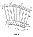
FIG. 1 illustrates a partial perspective view of a turbine disk with shrouded turbine blades installed according to the present disclosure; and -
FIG. 2 illustrates a perspective view of a turbine blade assembly device positioned to install shrouded turbine blades into a turbine disk according to the present disclosure. -
FIG. 3 illustrates another perspective view of the turbine blade assembly device ofFIG. 2 . - Referring now to the drawings and in particular to
FIG. 1 , a turbine disk generally referred to byreference number 10 is shown.Turbine disk 10 has a plurality of shroudedturbine blades 12 installed thereon.Turbine disk 10 has anouter rim 24 that receives ablade root 22 ofturbine blade 12.Turbine disk 10 has a plurality ofbroach slots 14 in theouter rim 24 that receive theblade root 22 ofturbine blade 12. Eachturbine blade 12 has an abuttingouter shroud 26 on thedistal end 18 ofturbine blade 12. Theouter shrouds 26 are commonly referred to as a z-notch 20 and overlap when viewed in the axial direction. - Referring now to
FIGS. 2 and3 , a turbine blade assembly device according to the present disclosure is shown, generally referred to byreference number 30.Assembly device 30 has a fixedvertical pivot bar 32 mounted to the ground outside of theturbine disk 10.Vertical pivot bar 32 is perpendicularly attached to a horizontaladjustable arm 34 via an adjustablepivoting yoke mechanism 36.Pivoting yoke mechanism 36 allows forvertical height adjustment 38 andradial adjustment 40 ofhorizontal arm 34 to accommodate various size disks and to permit loading and unloading of thedisk 10 onto a power rotary table 42 where thedisk 10 is assembled. -
Horizontal arm 34 can be segmented and can adjust and rotate with the use of wrist pins.Horizontal arm 34 can also have visual indicators that monitor the appropriate blade position. - In an exemplary embodiment, rotary table 42 is a lazy susan style table. Rotary table 42 is adjustable for height in a
vertical direction 44. Table 42 has amotor 46 that rotates the table in a counterclockwise or clockwisedirection 48 as viewed from the top. Table 42 has a pawl that can disengage the automatic rotation of table 42 for manual adjustment to prevent full seating of the blades if the blade shrouds bind. Acenter locating ring 52 is located in the center of table 42 that centers theturbine disk 10 on the table to accommodate disks with different diameters. - A
blade positioning belt 54 circumvents the outer diameter of theturbine disk 10 and provides a rest for theblade roots 22 as they are initially pushed into thebroach slots 14.Positioning belt 54 maintains a consistent position for eachblade 12 relative to other blades in thedisk 10 before they are fully installed into theslots 14.Positioning belt 54 has frictional contact with thedisk 10 to prevent slipping initially, but it is fabricated such that it ensures no damage to theblades 12 or thedisk 10 and so that it has the ability to slide down as theblades 12 are pushed downward.Positioning belt 54 can have tabs on the lower edge that are attached under thedisk 10 to provide a proper alignment of theblades 12. - A
roller assembly 56 is attached tohorizontal arm 34 via a vertical acme screw that, together with thepivoting yoke mechanism 36, provides a large vertical force and incremental blade displacement without binding. Alternatively, a rack-and-pinion displacement system could be used.Roller assembly 56 slowly lowers aseating wheel 58 onto theblade roots 22, while theblades 12 are initially installed into theturbine disk 10.Seating wheel 58 gradually pushes the blades downward into the turbinedisk broach slots 14 as thedisk 10 is rotated on table 42 viamotor 46.Roller assembly 56 is electrically activated to adjust radially and vertically but it may be disengaged to allow for manual adjustment as required. In an exemplary embodiment, a linear actuator is utilized to controlroller assembly 56.Seating wheel 58 exerts equal pressure on theblade roots 22 to position them properly into thedisk 10. The seating wheel is constructed of a non-marring material, for example urethane, to prevent damage to theblades 22 and theturbine disk 10. - A
saddle 60 is attached tovertical pivot bar 32 via a radially and heightadjustable ramp support 66.Saddle 60 is positioned beneath theturbine blade shrouds 26 to provide support and prevent theshrouds 26 from jamming when they are seated in thedisk 10.Saddle 60 prevents theturbine blades 12 from sinking when theblade 12 is pushed into thebroach slots 14.Saddle 60 can be adjusted to accommodate different blade/disk configurations. In the event of damage,saddle 60 can be easily replaced. - In an exemplary embodiment of turbine
blade assembly device 30,saddle 60 is manufactured from a plastic, rubber or nylon material and its contact face is crowned to help lift theblade tip 18 into position. Theblade tips 18 are lifted into position via an upward tip action created either mechanically or electromechanically bysaddle 60 that is simultaneous to the downward movement ofseating wheel 58. Thesaddle 60 and theroller assembly 56, can be positioned independent of one another on thevertical pivot bar 32 or they can be synchronized to the rotation of table 42. Once the positions are set for a particular turbine disk size, thesaddle 60 androller assembly 56 must lower at the same rate as table 42 rotates. This method of seating the blades is particularly useful to help properly seat theblades 12 and prevent them from binding. Theroller 58 also prevents damage to theblade root 22. - Turbine
blade assembly device 30 can optionally utilize one or more reaction rings 62 installed around the top of theblade roots 22 to provide a bearing surface betweenseating wheel 58 and the upper surface of the turbine blade roots (inFIG. 3 a portion of thereaction ring 62 is omitted from the illustration). The reaction rings 62 can be constructed of nylon, plastic or rubber. The reaction rings 62 conform to the upper surface of theblade root 22 and theturbine disk 10 and provide pressure distribution and accurate control at the point where theseating wheel 58 contacts thedisk 10. - Adapter rings, or stops, are used to secure the turbine disk to rotary table 42 and provide features to ensure the
disk 10 is concentric with the table 42. Adapter rings must provide clearance for a sling fixture that is used to load and unload thedisk 10 onto rotary table 42. A gage can be used to verify that theturbine disk 10 and theblade positioning belt 54 are properly positioned. - Turbine
blade assembly device 30 can have a blade force indicator that measures the force required to fully seat theturbine blades 12. If the force exceeds a set maximum force, the blade force indicator automatically brings the rotation of table 42 to a halt and sounds an alarm indicating that theturbine blades 12 are locked and may require mechanic intervention. Alternatively, the blade force indicator may be a visual color indicator that signals when over pressurization of the blades begins 12 to occur. - Advantageously, turbine
blade assembly device 30 installsturbine blades 12 into aturbine disk 10 without having to manually hammer eachblade 12 into place. The device exerts a controlled amount of pressure on theblade roots 22 while providing positive control of the engagement between theturbine blade root 22 and thebroach slots 14 at therim 18 of thedisk 10. Additionally, the device ensures a proper blade angle by providing a support beneath the blade shrouds 26 to prevent binding or blade damage. - The turbine blade installation method of the present disclosure simulates manual hammering using a roller
blade assembly device 30. A sling fixture is used to lift theturbine disk 10 onto, and off of, rotary table 42. Thedisk 10 is centered on the table 42 and secured using four adapter rings spaced about ninety degrees from one another.Blade positioning belt 54 is wrapped tightly around the outer diameter of theturbine disk 10 where the adapter rings are located. A gage or visual inspection can be used to verify proper belt location. Theturbine blades 12 are positioned on thebelt 54 without forcing them down so that theblade roots 22 are not fully engaged with the broach slots. This allows theouter shrouds 26 to be flexed into position, abutted and interlocked with the adjacent outer shrouds 26. The reaction rings 62 are installed around the top of theblade roots 22 to provide a bearing surface betweenseating wheel 58 and the upper surface of theturbine blade roots 22. - The turbine
blade assembly device 30 is adjusted and positioned on top of the blade roots 22 (and reaction rings 62 if present). Theroller assembly 56 slowly lowers seatingwheel 58 onto the blade roots 22 (and reaction rings 62 if present). Seatingwheel 58 gradually pushes theblade roots 22 downward into the turbinedisk broach slots 14 as thedisk 10 is rotated on table 42 bymotor 46. As theblades roots 22 are pushed downward byseating wheel 58, the blade shrouds 26 are simultaneously lifted upward via an upward tip action created either mechanically or electromechanically bysaddle 60. Thesaddle 60 and theroller assembly 56 can be positioned independent of one another on thevertical pivot bar 32 or they may be synchronized to counterclockwise rotation of table 42. Once the positions are set for a particular turbine disk size, they must lower at the same rate as table 42 rotates. - While the present disclosure has been described with reference to one or more exemplary embodiments, it will be understood by those skilled in the art that various changes may be made and equivalents may be substituted for elements thereof without departing from the scope of the present disclosure. For example, blades installed into either compressor disks or turbine disks would benefit from the present device and method. In addition, many modifications may be made to adapt a particular situation or material to the teachings of the disclosure without departing from the scope thereof. Therefore, it is intended that the present disclosure not be limited to the particular embodiment(s) disclosed as the best mode contemplated, but that the disclosure will include all embodiments falling within the scope of the appended claims.
Claims (15)
- A device (30) for installing blades (12) into a slotted disk (10) comprising:a rotary table (42) for supporting and providing rotary motion to the disk (10);a horizontal adjustable arm (34);a vertical pivot bar (32) perpendicularly attached to a first end of said horizontal adjustable arm (34);a roller assembly (56) attached to a second end of said horizontal adjustable arm (34), said roller assembly (56) for engaging the blade roots (22);a saddle (60) attached to said vertical pivot bar (32), said saddle for positioning beneath the blade tips (18); andwherein said roller assembly (56) can exert downward force on the roots (22) and the saddle (60) can exert upward force on the tips (18) as the table (42) rotates, thereby seating the blades (12) in the slots.
- The device of claim 1, wherein said horizontal adjustable arm (34) is attached to said vertical pivot bar (32) via an adjustable pivoting yoke mechanism (36).
- The device of claim 2, wherein said pivoting yoke mechanism (36) provides for vertical height adjustment and radial adjustment of said horizontal adjustable arm (34).
- The device of any preceding claim, further comprising a blade positioning belt (54) that circumvents an outer diameter of the disk (10).
- The device of any preceding claim, wherein said rotary table (42) is rotatable by a motor (46).
- The device of claim 5, wherein said motor (46) is disengageable to allow manual adjustment of said rotary table (42).
- The device of any preceding claim, wherein said rotary table (42) comprises a center locating ring (52) to center the disk (10) on said rotary table (42).
- The device of any preceding claim, wherein said roller assembly (56) comprises a seating wheel (58) for contacting the blade roots (22).
- The device of any preceding claim, wherein said roller assembly (56) is electrically activated providing vertical height adjustment and radial adjustment.
- The device of claim 9, wherein said roller assembly (56) is disengageable to provide for manual adjustment.
- The device of any preceding claim, further comprising a plurality of reaction rings (62), said rings installable between the root (22) of the blades (12) and the roller assembly (56).
- A method of installing blades (12) into a disk (10) comprising the steps of:centering and securing a disk to a rotary table (42), for example using a center locating ring (52) and a plurality of adapter rings;wrapping a blade positioning belt (54) around an outer diameter of the disk (10);positioning a plurality of blades (22) on said positioning belt (54) without engaging the blades (22) with the disk (10);lowering a seating wheel (58) attached to a roller assembly (56) onto the blades (22) of the disk so that the blades (22) are pushed downward into a plurality of broach slots in the disk (10).
- The method of claim 12, further comprising rotating a rotary table (42) that holds the disk (10) in a counterclockwise direction as the blades (22) are installed into the disk (10).
- The method of claim 12 or 13, further comprising lifting the blades (22) upward via a saddle (60) located beneath the blades (22) simultaneously to the downward motion provided by said seating wheel (58), wherein the lifting and the downward motion occur at opposite ends of the blades (22).
- The method of claim 14, wherein the downward motion of said seating wheel (58) and the upward motion of said saddle (60) is synchronized to the rotation of said rotary table (42).
Applications Claiming Priority (1)
| Application Number | Priority Date | Filing Date | Title |
|---|---|---|---|
| US12/009,715 US7971334B2 (en) | 2008-01-22 | 2008-01-22 | Bladed disk assembly method and roller device |
Publications (3)
| Publication Number | Publication Date |
|---|---|
| EP2083146A2 true EP2083146A2 (en) | 2009-07-29 |
| EP2083146A3 EP2083146A3 (en) | 2012-05-30 |
| EP2083146B1 EP2083146B1 (en) | 2014-03-05 |
Family
ID=40469958
Family Applications (1)
| Application Number | Title | Priority Date | Filing Date |
|---|---|---|---|
| EP09250153.5A Active EP2083146B1 (en) | 2008-01-22 | 2009-01-20 | Turbine disk assembly method and device |
Country Status (2)
| Country | Link |
|---|---|
| US (1) | US7971334B2 (en) |
| EP (1) | EP2083146B1 (en) |
Cited By (5)
| Publication number | Priority date | Publication date | Assignee | Title |
|---|---|---|---|---|
| EP2354456A3 (en) * | 2009-12-30 | 2011-12-21 | General Electric Company | Fixture and method for mounting articulated turbine buckets |
| EP2341219A3 (en) * | 2010-01-04 | 2012-08-22 | General Electric Company | Apparatus and method for turbine blade installation |
| FR3008448A1 (en) * | 2013-07-15 | 2015-01-16 | Snecma | REMOVAL DEVICE FOR AUBES |
| EP2944775A1 (en) * | 2014-05-12 | 2015-11-18 | Siemens Aktiengesellschaft | Method for assembling a turbine assembly |
| EP2653651A3 (en) * | 2012-04-17 | 2017-11-15 | General Electric Company | Turbine inspection system and related method of operation |
Families Citing this family (16)
| Publication number | Priority date | Publication date | Assignee | Title |
|---|---|---|---|---|
| US7975354B2 (en) * | 2007-02-08 | 2011-07-12 | United Technologies Corporation | Bladed disk assembly method and impact device |
| PL2354537T3 (en) * | 2010-02-08 | 2014-01-31 | Geosea Nv | Method and device for assembling a wind turbine at sea |
| US10309232B2 (en) | 2012-02-29 | 2019-06-04 | United Technologies Corporation | Gas turbine engine with stage dependent material selection for blades and disk |
| US9597759B2 (en) | 2014-03-28 | 2017-03-21 | Pratt & Whitney Canada Corp. | Positioning assembly and method |
| US10280802B2 (en) * | 2016-09-07 | 2019-05-07 | General Electric Company | Turbine casing jack |
| US10563665B2 (en) | 2017-01-30 | 2020-02-18 | Rolls-Royce North American Technologies, Inc. | Turbomachine stage and method of making same |
| CN108515321A (en) * | 2018-04-23 | 2018-09-11 | 胡鹏飞 | It is a kind of to be rolled into pipe with rectangle steel plate or pipe material manufactures wheel spoke new method |
| FR3090030B1 (en) | 2018-12-12 | 2020-11-20 | Safran Aircraft Engines | Retaining device for removing a turbine engine impeller and method using it |
| EP3928920A4 (en) * | 2019-03-29 | 2022-03-23 | Hirata Corporation | Mounting device |
| CN109968084B (en) * | 2019-04-04 | 2020-07-17 | 哈尔滨汽轮机厂有限责任公司 | Clamping device for turning inner hole of guide vane of gas turbine |
| CN112975335A (en) * | 2019-12-16 | 2021-06-18 | 中国航发商用航空发动机有限责任公司 | Turbine blade mounting system and method |
| CN111922278B (en) * | 2020-08-13 | 2022-01-14 | 哈尔滨电机厂有限责任公司 | Process method for riveting fan blades of collector ring fan of generator rotor |
| CN115070665B (en) * | 2021-03-15 | 2023-10-31 | 中国航发商用航空发动机有限责任公司 | Mounting tool and mounting method for turbine disk baffle ring |
| FR3126636A1 (en) * | 2021-09-06 | 2023-03-10 | Safran Aircraft Engines | LOADING BLADES ON A WHEEL |
| CN114633090B (en) * | 2022-03-29 | 2023-03-31 | 南京航空航天大学 | Automatic assembly quality of whole dish of aeroengine interlocking type rotor blade |
| CN115075887B (en) * | 2022-07-15 | 2025-06-17 | 中国航发沈阳发动机研究所 | A balanced connection device for a turbine disc rotor of an aircraft engine |
Family Cites Families (7)
| Publication number | Priority date | Publication date | Assignee | Title |
|---|---|---|---|---|
| US1269144A (en) * | 1915-07-19 | 1918-06-11 | James Williamson | Method of blading turbines. |
| US2821778A (en) * | 1957-03-07 | 1958-02-04 | Lau Blower Co | Fixture for assembling blower wheels |
| US4798520A (en) | 1987-05-22 | 1989-01-17 | Westinghouse Electric Corp. | Method for installing integral shroud turbine blading |
| DE3802741C2 (en) | 1988-01-30 | 1997-02-13 | Asea Brown Boveri | Method of bracing blades |
| US6061886A (en) | 1997-07-11 | 2000-05-16 | Honda Giken Kogyo Kabushiki Kaisha | Turbine blade fitting apparatus and fitting method |
| US7320172B1 (en) * | 2005-01-10 | 2008-01-22 | Exedy America Corporation | Apparatus for positioning inserts in a receptacle |
| US7975354B2 (en) * | 2007-02-08 | 2011-07-12 | United Technologies Corporation | Bladed disk assembly method and impact device |
-
2008
- 2008-01-22 US US12/009,715 patent/US7971334B2/en active Active
-
2009
- 2009-01-20 EP EP09250153.5A patent/EP2083146B1/en active Active
Cited By (9)
| Publication number | Priority date | Publication date | Assignee | Title |
|---|---|---|---|---|
| EP2354456A3 (en) * | 2009-12-30 | 2011-12-21 | General Electric Company | Fixture and method for mounting articulated turbine buckets |
| EP2341219A3 (en) * | 2010-01-04 | 2012-08-22 | General Electric Company | Apparatus and method for turbine blade installation |
| US8555473B2 (en) | 2010-01-04 | 2013-10-15 | General Electric Company | Apparatus and method for turbine blade installation |
| EP2653651A3 (en) * | 2012-04-17 | 2017-11-15 | General Electric Company | Turbine inspection system and related method of operation |
| FR3008448A1 (en) * | 2013-07-15 | 2015-01-16 | Snecma | REMOVAL DEVICE FOR AUBES |
| WO2015007979A1 (en) * | 2013-07-15 | 2015-01-22 | Snecma | Dismantling device for blades and corresponding dismantling method |
| US10533434B2 (en) | 2013-07-15 | 2020-01-14 | Safran Aircraft Engines | Dismantling device for blades and corresponding dismantling method |
| EP2944775A1 (en) * | 2014-05-12 | 2015-11-18 | Siemens Aktiengesellschaft | Method for assembling a turbine assembly |
| WO2015173002A1 (en) * | 2014-05-12 | 2015-11-19 | Siemens Aktiengesellschaft | Method for assembling a turbine assembly |
Also Published As
| Publication number | Publication date |
|---|---|
| EP2083146B1 (en) | 2014-03-05 |
| EP2083146A3 (en) | 2012-05-30 |
| US7971334B2 (en) | 2011-07-05 |
| US20090183349A1 (en) | 2009-07-23 |
Similar Documents
| Publication | Publication Date | Title |
|---|---|---|
| EP2083146B1 (en) | Turbine disk assembly method and device | |
| US7975354B2 (en) | Bladed disk assembly method and impact device | |
| EP1775067B1 (en) | Fixture and method for the grinding of blade tips of a turbine rotor | |
| US9217461B2 (en) | Systems and methods for preloading a bearing and aligning a lock nut | |
| US10690174B2 (en) | Systems and methods for preloading a bearing and aligning a lock nut | |
| EP3447254B1 (en) | Inlet guide vane alignment apparatus and method | |
| EP2299064B1 (en) | Variable stator vane assembly and corresponding compressor for a gas turbine engine | |
| EP2469043A2 (en) | Axial retention feature for gas turbine engine vanes | |
| JP2006275045A (en) | Split ring retainer and method for retaining outer air seal | |
| US9566699B1 (en) | Systems and methods for preloading a bearing and installing a tamper indicating member | |
| US20130259688A1 (en) | Pitch lock system | |
| US9126294B2 (en) | Tool for rotor assembly and disassembly | |
| EP3330040B1 (en) | Combustion liner tool | |
| US20170326714A1 (en) | Systems and methods for preloading a bearing and installing a tamper indicating member | |
| JP2011137447A (en) | Fixture and method for mounting articulated turbine buckets | |
| US8651817B2 (en) | Aerofoil blade assembly | |
| EP3421408B1 (en) | Turbomachine component handling assembly | |
| US7344355B2 (en) | Variable stator vane assemblies | |
| EP3722564B1 (en) | Vane arm assembly for a gas turbine engine, corresponding method of redundantly axially retaining a vane arm, and gas turbine engine | |
| CN109129360B (en) | Assistant rotary table for assembling automobile power assembly | |
| US11167404B2 (en) | Separable rotary table | |
| CN111511505B (en) | Tool for removing annular components of a turbine engine | |
| US20080250629A1 (en) | Assembly and method for installing a disc clamp | |
| US20070074554A1 (en) | Method and apparatus for self indexing portable automated tenon peening | |
| CN112313396B (en) | Retaining system for blade wheel removal |
Legal Events
| Date | Code | Title | Description |
|---|---|---|---|
| PUAI | Public reference made under article 153(3) epc to a published international application that has entered the european phase |
Free format text: ORIGINAL CODE: 0009012 |
|
| AK | Designated contracting states |
Kind code of ref document: A2 Designated state(s): AT BE BG CH CY CZ DE DK EE ES FI FR GB GR HR HU IE IS IT LI LT LU LV MC MK MT NL NO PL PT RO SE SI SK TR |
|
| AX | Request for extension of the european patent |
Extension state: AL BA RS |
|
| PUAL | Search report despatched |
Free format text: ORIGINAL CODE: 0009013 |
|
| RIC1 | Information provided on ipc code assigned before grant |
Ipc: B23P 15/00 20060101ALI20120420BHEP Ipc: F01D 25/28 20060101ALI20120420BHEP Ipc: F01D 5/00 20060101AFI20120420BHEP Ipc: F01D 5/30 20060101ALI20120420BHEP |
|
| AK | Designated contracting states |
Kind code of ref document: A3 Designated state(s): AT BE BG CH CY CZ DE DK EE ES FI FR GB GR HR HU IE IS IT LI LT LU LV MC MK MT NL NO PL PT RO SE SI SK TR |
|
| AX | Request for extension of the european patent |
Extension state: AL BA RS |
|
| 17P | Request for examination filed |
Effective date: 20121128 |
|
| AKX | Designation fees paid |
Designated state(s): DE GB |
|
| GRAJ | Information related to disapproval of communication of intention to grant by the applicant or resumption of examination proceedings by the epo deleted |
Free format text: ORIGINAL CODE: EPIDOSDIGR1 |
|
| GRAP | Despatch of communication of intention to grant a patent |
Free format text: ORIGINAL CODE: EPIDOSNIGR1 |
|
| INTG | Intention to grant announced |
Effective date: 20130815 |
|
| GRAS | Grant fee paid |
Free format text: ORIGINAL CODE: EPIDOSNIGR3 |
|
| GRAA | (expected) grant |
Free format text: ORIGINAL CODE: 0009210 |
|
| AK | Designated contracting states |
Kind code of ref document: B1 Designated state(s): DE GB |
|
| REG | Reference to a national code |
Ref country code: GB Ref legal event code: FG4D |
|
| REG | Reference to a national code |
Ref country code: DE Ref legal event code: R096 Ref document number: 602009022162 Country of ref document: DE Effective date: 20140417 |
|
| REG | Reference to a national code |
Ref country code: DE Ref legal event code: R097 Ref document number: 602009022162 Country of ref document: DE |
|
| PLBE | No opposition filed within time limit |
Free format text: ORIGINAL CODE: 0009261 |
|
| STAA | Information on the status of an ep patent application or granted ep patent |
Free format text: STATUS: NO OPPOSITION FILED WITHIN TIME LIMIT |
|
| 26N | No opposition filed |
Effective date: 20141208 |
|
| REG | Reference to a national code |
Ref country code: DE Ref legal event code: R097 Ref document number: 602009022162 Country of ref document: DE Effective date: 20141208 |
|
| REG | Reference to a national code |
Ref country code: DE Ref legal event code: R082 Ref document number: 602009022162 Country of ref document: DE Representative=s name: SCHMITT-NILSON SCHRAUD WAIBEL WOHLFROM PATENTA, DE |
|
| REG | Reference to a national code |
Ref country code: DE Ref legal event code: R082 Ref document number: 602009022162 Country of ref document: DE Representative=s name: SCHMITT-NILSON SCHRAUD WAIBEL WOHLFROM PATENTA, DE Ref country code: DE Ref legal event code: R081 Ref document number: 602009022162 Country of ref document: DE Owner name: UNITED TECHNOLOGIES CORP. (N.D.GES.D. STAATES , US Free format text: FORMER OWNER: UNITED TECHNOLOGIES CORP., HARTFORD, CONN., US |
|
| REG | Reference to a national code |
Ref country code: DE Ref legal event code: R081 Ref document number: 602009022162 Country of ref document: DE Owner name: RAYTHEON TECHNOLOGIES CORPORATION (N.D.GES.D.S, US Free format text: FORMER OWNER: UNITED TECHNOLOGIES CORP. (N.D.GES.D. STAATES DELAWARE), FARMINGTON, CONN., US Ref country code: DE Ref legal event code: R081 Ref document number: 602009022162 Country of ref document: DE Owner name: RTX CORPORATION (N.D.GES.D. STAATES DELAWARE),, US Free format text: FORMER OWNER: UNITED TECHNOLOGIES CORP. (N.D.GES.D. STAATES DELAWARE), FARMINGTON, CONN., US |
|
| P01 | Opt-out of the competence of the unified patent court (upc) registered |
Effective date: 20230519 |
|
| REG | Reference to a national code |
Ref country code: DE Ref legal event code: R081 Ref document number: 602009022162 Country of ref document: DE Owner name: RTX CORPORATION (N.D.GES.D. STAATES DELAWARE),, US Free format text: FORMER OWNER: RAYTHEON TECHNOLOGIES CORPORATION (N.D.GES.D.STAATES DELAWARE), ARLINGTON, VA, US |
|
| PGFP | Annual fee paid to national office [announced via postgrant information from national office to epo] |
Ref country code: GB Payment date: 20251220 Year of fee payment: 18 |
|
| PGFP | Annual fee paid to national office [announced via postgrant information from national office to epo] |
Ref country code: DE Payment date: 20251217 Year of fee payment: 18 |