EP2083060A1 - Process and equipment for fluid catalytic cracking for the production of middle distillates of low aromaticity - Google Patents
Process and equipment for fluid catalytic cracking for the production of middle distillates of low aromaticity Download PDFInfo
- Publication number
- EP2083060A1 EP2083060A1 EP09250166A EP09250166A EP2083060A1 EP 2083060 A1 EP2083060 A1 EP 2083060A1 EP 09250166 A EP09250166 A EP 09250166A EP 09250166 A EP09250166 A EP 09250166A EP 2083060 A1 EP2083060 A1 EP 2083060A1
- Authority
- EP
- European Patent Office
- Prior art keywords
- catalyst
- catalytic cracking
- fluid catalytic
- feed
- reactor
- Prior art date
- Legal status (The legal status is an assumption and is not a legal conclusion. Google has not performed a legal analysis and makes no representation as to the accuracy of the status listed.)
- Granted
Links
Images


Classifications
-
- C—CHEMISTRY; METALLURGY
- C10—PETROLEUM, GAS OR COKE INDUSTRIES; TECHNICAL GASES CONTAINING CARBON MONOXIDE; FUELS; LUBRICANTS; PEAT
- C10G—CRACKING HYDROCARBON OILS; PRODUCTION OF LIQUID HYDROCARBON MIXTURES, e.g. BY DESTRUCTIVE HYDROGENATION, OLIGOMERISATION, POLYMERISATION; RECOVERY OF HYDROCARBON OILS FROM OIL-SHALE, OIL-SAND, OR GASES; REFINING MIXTURES MAINLY CONSISTING OF HYDROCARBONS; REFORMING OF NAPHTHA; MINERAL WAXES
- C10G11/00—Catalytic cracking, in the absence of hydrogen, of hydrocarbon oils
- C10G11/14—Catalytic cracking, in the absence of hydrogen, of hydrocarbon oils with preheated moving solid catalysts
- C10G11/18—Catalytic cracking, in the absence of hydrogen, of hydrocarbon oils with preheated moving solid catalysts according to the "fluidised-bed" technique
-
- C—CHEMISTRY; METALLURGY
- C10—PETROLEUM, GAS OR COKE INDUSTRIES; TECHNICAL GASES CONTAINING CARBON MONOXIDE; FUELS; LUBRICANTS; PEAT
- C10G—CRACKING HYDROCARBON OILS; PRODUCTION OF LIQUID HYDROCARBON MIXTURES, e.g. BY DESTRUCTIVE HYDROGENATION, OLIGOMERISATION, POLYMERISATION; RECOVERY OF HYDROCARBON OILS FROM OIL-SHALE, OIL-SAND, OR GASES; REFINING MIXTURES MAINLY CONSISTING OF HYDROCARBONS; REFORMING OF NAPHTHA; MINERAL WAXES
- C10G11/00—Catalytic cracking, in the absence of hydrogen, of hydrocarbon oils
- C10G11/02—Catalytic cracking, in the absence of hydrogen, of hydrocarbon oils characterised by the catalyst used
-
- C—CHEMISTRY; METALLURGY
- C10—PETROLEUM, GAS OR COKE INDUSTRIES; TECHNICAL GASES CONTAINING CARBON MONOXIDE; FUELS; LUBRICANTS; PEAT
- C10G—CRACKING HYDROCARBON OILS; PRODUCTION OF LIQUID HYDROCARBON MIXTURES, e.g. BY DESTRUCTIVE HYDROGENATION, OLIGOMERISATION, POLYMERISATION; RECOVERY OF HYDROCARBON OILS FROM OIL-SHALE, OIL-SAND, OR GASES; REFINING MIXTURES MAINLY CONSISTING OF HYDROCARBONS; REFORMING OF NAPHTHA; MINERAL WAXES
- C10G11/00—Catalytic cracking, in the absence of hydrogen, of hydrocarbon oils
- C10G11/02—Catalytic cracking, in the absence of hydrogen, of hydrocarbon oils characterised by the catalyst used
- C10G11/04—Oxides
-
- C—CHEMISTRY; METALLURGY
- C10—PETROLEUM, GAS OR COKE INDUSTRIES; TECHNICAL GASES CONTAINING CARBON MONOXIDE; FUELS; LUBRICANTS; PEAT
- C10G—CRACKING HYDROCARBON OILS; PRODUCTION OF LIQUID HYDROCARBON MIXTURES, e.g. BY DESTRUCTIVE HYDROGENATION, OLIGOMERISATION, POLYMERISATION; RECOVERY OF HYDROCARBON OILS FROM OIL-SHALE, OIL-SAND, OR GASES; REFINING MIXTURES MAINLY CONSISTING OF HYDROCARBONS; REFORMING OF NAPHTHA; MINERAL WAXES
- C10G2400/00—Products obtained by processes covered by groups C10G9/00 - C10G69/14
- C10G2400/04—Diesel oil
Definitions
- the present invention relates to a process and equipment for fluid catalytic cracking (FCC), for the production of middle distillates of low aromaticity, in the absence of added hydrogen, from heavy hydrocarbon feedstocks of various origins.
- FCC fluid catalytic cracking
- the invention further relates to FCC equipment for the production of the above products.
- the purpose of the FCC process is to convert liquid hydrocarbons of high molecular weight, which generally have an Initial Boiling Point (IBP) in the range from 320°C to 390°C, or higher, and typical densities in the range from 8 to 28°API, such as oil refinery effluents produced from side cuts from vacuum towers, called heavy vacuum gas oil (HVGO), or from the bottom of atmospheric towers, called atmospheric residue (ATR), or mixtures of these effluents, to light hydrocarbon fractions such as gasoline (IBP around 30°C) and liquefied petroleum gas (LPG) (maximum vapour pressure of 15 kgf/cm 2 at 37.8°C).
- IBP Initial Boiling Point
- HVGO heavy vacuum gas oil
- ATR atmospheric residue
- light hydrocarbon fractions such as gasoline (IBP around 30°C) and liquefied petroleum gas (LPG) (maximum vapour pressure of 15 kgf/cm 2 at 37.8°C).
- the preheated hydrocarbon feed is injected near the bottom of a conversion zone or "riser", where it comes in contact with the stream of regenerated catalyst, from which it receives a sufficient amount of heat to vaporize it and supply the requirements of the endothermic reactions that predominate in the process.
- the riser is a long vertical pipe having dimensions in industrial units of about 0.5 m to 2.0 m in diameter, with a height of 25-40 m, where chemical reactions take place.
- the spent catalyst After the riser, the spent catalyst, with coke deposited on its surface and in its pores, is separated from the reaction products and sent to the regenerator for burning the coke to restore its activity and to generate heat which, transferred by the catalyst to the riser, will be utilized by the process.
- the conditions prevailing at the point of introduction of the feed in the riser are decisive for the products that form in the reaction. In this region there is the initial mixing of the feed with the regenerated catalyst, heating of the feed up to the boiling point of its components and vaporization of the major portion of these components.
- the typical total residence time of the hydrocarbons in the riser is about 1 to 4 seconds.
- thermal cracking promotes the formation of by-products such as coke and fuel gas, principally in the cracking of residual feeds.
- the coke poisons the acid sites and may eventually block the pores of the catalyst. Therefore thermal cracking at the bottom of the riser competes undesirably with catalytic cracking, the purpose of the process.
- optimization of the conversion of the feed usually requires maximum removal of the coke from the catalyst in the regenerator. Combustion of the coke can take place in conditions of partial combustion or complete combustion.
- the gases produced by the combustion of the coke are mainly constituted of CO 2 , CO and H 2 O and the content of coke in the regenerated catalyst is of the order of 0.1 to 0.3 wt.%.
- complete combustion carried out in the presence of a greater excess of oxygen, practically all the CO produced in the reaction is converted to CO 2 .
- the increase in coke in the spent catalyst results in an increase in combustion of coke in the regenerator per unit of mass of circulating catalyst.
- the heat is removed from the regenerator via the combustion gas and more effectively by the stream of hot regenerated catalyst.
- An increase in the content of coke on the spent catalyst increases the temperature of the regenerated catalyst and the temperature difference between the regenerator and the reactor.
- catalyst circulation rate a reduction in the flow of regenerated catalyst to the reactor, usually called catalyst circulation rate, is desirable in order to meet the thermal demand of the reactor and maintain the same reaction temperature.
- the lower catalyst circulation rate required by the larger temperature difference between the regenerator and the reactor results in reduction of the catalyst/oil ratio, decreasing the conversion, but also decreasing the deposition of coke on the catalyst, in contrast to the initial effect of increase in the content of coke.
- the circulation of catalyst from the regenerator to the reactor is determined by the thermal demand of the riser and by the temperature that is established in the regenerator, which depends on the production of coke.
- the process of catalytic cracking functions in conditions of thermal balance, and, for the reasons stated, operation at very high regeneration temperature is undesirable.
- the temperatures of the regenerator, and therefore of the regenerated catalyst are kept below 760°C, preferably below 732°C, as the loss of activity would be very severe above this value.
- the desirable operating range is from 685°C to 710°C. The lower value is dictated primarily by the need to ensure proper combustion of the coke.
- catalyst coolers remove heat from a catalyst stream from the regenerator, returning a substantially cooled catalyst stream to this vessel.
- an external stream is injected separately at an upper point of the riser for the purpose of controlling the temperature profile of the latter, so as to maintain the initial section of the riser at a relatively higher temperature without altering the temperature of the top of the riser (reaction temperature or TRX).
- This control can also be achieved by recycling heavy naphtha, as taught in US patent 5,087,349 .
- Publication WO 93/22400 mentions the possibility of injection, along the riser, of a cracked product, such as LCO, with the aim of cooling the riser and consequently promoting an increase in circulation of catalyst and permitting improvement of the performance of additives based on ZSM-5.
- LCO is one of the by-products of the FCC, representing from 15% to 25% of the yield and corresponding to the distillation range typically between 220°C and 340°C.
- the LCO has a high concentration of aromatics, even exceeding 80 wt.% of the total hydrocarbons present in said LCO fraction.
- the high concentration of aromatics in LCO means that it has very poor knock characteristics in diesel engines (low cetane number) and high density.
- the high aromatics content also makes it difficult to improve its properties by hydrofining or desulphurization.
- US patent 6,416,656 teaches a process for simultaneously increasing the yield of diesel and LPG.
- the gasoline is recracked to increase the yield of LPG, being injected at a point below the feed nozzle.
- the process feed is injected at multiple points along the riser, reducing the contact time and hence increasing the yield of LCO.
- the reduced severity of the FCC riser for middle distillates means that the cracking of naphtha in these conditions is not very effective.
- the use of a reactor operating with long catalyst-oil contact time endows the invention with the possibility of producing a middle distillate of low aromaticity, while operating the industrial unit at conventional FCC temperatures. This avoids all the problems arising from operation at low temperatures. Moreover, there is a result of conversion of bottoms similar to the values found in industrial units that operate with high values of process conversion. Even better results are achieved using a dense-bed reactor combined with catalysts of low acidity or basic character.
- the invention relates to a process of catalytic cracking that preferably employs catalytic systems of lower activity than that of the conventional catalytic systems, of reduced acidity or of basic character, that promote reaction mechanisms that modify the composition of the feed, converting it to lighter hydrocarbons, and making it possible to increase the production of saturated hydrocarbons in the cracked products.
- catalytic systems are employed in a special reaction system and in appropriate operating conditions, so as to reach levels of conversion similar to those attained in the conventional processes of catalytic cracking and, at the same time, minimize the generation of aromatic hydrocarbons in the products.
- a dense-bed FCC reactor is preferably used, which provides long contact times in the risers, in comparison with the conventional FCC process, in which the reactor has entrained-bed fluid dynamics. This guarantees a process conversion level similar to the levels processed in conventional FCC units, which use high-activity catalysts based on zeolite Y.
- the present invention offers solutions to a number of problems arising from the operation of FCC at low severity, as it operates with reaction temperatures similar to those employed in conventional FCC processes.
- conditions of low severity mean a reaction temperature in the range from 460°C to 520°C.
- this range of reaction temperature results in a marked loss of rectification efficiency, with significant effects on the entrainment of hydrocarbons to the regenerator, and therefore on the heating of the latter.
- the reactor operates at temperatures normally employed in FCC units, increasing the process severity on the basis of the contact time and the catalyst/oil ratio.
- catalysts of low activity with reduced acidity or with basic character, it is possible to operate with high conversions and products with low aromaticity.
- stage of rectification of the spent catalyst, for removal of the residual hydrocarbons has an efficiency similar to that achieved in conventional FCC units, since there is no need to operate the unit with moderate temperatures to reduce the severity.
- the technique envisages a process for catalytic cracking of heavy feeds, in the absence of added hydrogen, using a dense-bed reactor, that operates with high catalyst/oil mass ratio and long contact times, producing a middle distillate of low aromaticity and low yield of decanted oil.
- Said process employs catalysts that promote cracking reactions, while partially inhibiting the formation of aromatic molecules in the lighter products resulting from the reaction.
- WO 2007/082629 is also concerned with the purpose of maximization of LCO and reduction of aromatics in the products generated in the FCC process, describes the use of catalysts which, on the basis of their characteristics, could be applied in the present invention.
- the process preferably takes place in two stages, where the first stage employs mild operating conditions of low severity and the second uses conventional zeolitic FCC catalyst. Accordingly, to achieve high conversion in the process it is necessary to install two FCC units with conventional hardware, i.e. with cracking reactions in risers.
- the present invention provides a process that performs the entire conversion in a single stage, preferably based on the use of a dense-bed reactor. Furthermore, the operating conditions adopted are considered to be of high severity in comparison with the processes that maximize middle distillates, as the proposed invention employs high catalyst/oil mass ratios and extremely long contact times.
- the present invention proposes an alternative that is economically more attractive and gives excellent results in terms of yield and quality, according to the example given in the document.
- the proposed invention envisages the use of only one catalytic system of low activity in a process with only one stage operating with an extended contact time, a combination not foreseen in the literature.
- the overall result of the process according to the present invention is an increase in the yield of middle distillates of low aromaticity and petrochemical naphtha, said process and equipment used for carrying out said process being described and claimed in the present application.
- a process of fluid catalytic cracking using a reactor for production of middle distillates of low aromaticity from a feed comprising heavy hydrocarbons comprising: contacting the feed with a cracking catalyst for a time of at least 30 seconds.
- the contact time between the cracking catalyst and the feed is about 1 to 4 seconds.
- the present invention allows for longer residence times under typical FCC conditions, without increasing the residual fraction (340°C + cut) in the FCC products, normally used for low-value fuel oil.
- the invention produces a middle distinate of low aromoticity.
- the processor fluid catalytic cracking uses a dense-bed reactor.
- a dense bed reactor has a lower superficial fluid velocity than conventional FCC reactors.
- the feed is contacted with the cracking catalyst for a time of no more than 120 seconds.
- Contacting the catalyst and the feed for less than 120 seconds minimises the amount of fuel gas produced in the reactor. It is economically advantageous to promote increases in products of higher value in preference to the production of fuel gas. Further, this has additional process benefits such as allowing the use of smaller airblowers and wear gas compressors.
- the feed is contacted with the cracking catalyst for a time in the range of from 70 seconds to 90 seconds. This range of times provides a desirable balance between allowing sufficient cracking to produce the desired product, without the over-production of fuel gas.
- the processor fluid catalystic cracking further comprises performing the catalytic cracking at a reaction temperature in the range of from 500°C to 580°C, preferably from 520°C to 560°C, more preferably from 530°C to 550°C and even more preferably from 535°C to 545°C.
- a reaction temperature in the range of from 500°C to 580°C, preferably from 520°C to 560°C, more preferably from 530°C to 550°C and even more preferably from 535°C to 545°C.
- reaction temperature to extremely low values (e.g. 450°C) which promotes an increase in the fuel oil fraction of the FCC product.
- the fuel oil is of low economic value, and the present invention avoids the over production of fuel oil.
- the processor fluid catalystic cracking further comprises performing the catalytic cracking at a catalyst/oil mass ratio in the range of from 8-15, preferably 9-13 and more preferably at a catalyst/oil mass ratio of 10.
- a catalyst/oil mass ratio in the range of from 8-15, preferably 9-13 and more preferably at a catalyst/oil mass ratio of 10.
- Existing FCC reactors optimised for the production of middle distillates are operated at low temperatures.
- catalyst which carries heat
- the present invention allows for higher catalyst/oil mass ratio.
- the processor fluid catalytic cracking is performed in the absence of hydrogen.
- the processor fluid catalytic cracking uses a cracking catalyst of low activity such that the catalyst would achieve a conversion of the fluid catalytic cracking process feed of at most 40% with a catalyst/oil mass ratio of about 10, a reaction temperature of 540°C and feed-catalyst contact time of less than 10 seconds.
- the use of a catalyst with a low activity increases the yield of middle fractions, whilst the reducing the content of aromatics in the middle fraction.
- the processor fluid catalytic cracking uses a catalyst of reduced acidity or basic character.
- catalysts promote cracking reactions, whilst partially inhibiting the formation of aromatic molecules in the lighter products.
- the catalysts with a basic character for use in the invention are such that, when measured by temperature programmed CO 2 desorption monitored by mass spectrometry (TPD/MS-CO 2 ), they evolve at least 50 micromoles of CO 2 /g of catalyst, and more preferably at least 100 micromoles of CO 2 /g.
- TPD/MS-CO 2 temperature programmed CO 2 desorption monitored by mass spectrometry
- the catalysts with reduced protic acidity for use with the the present invention are such that their protic acidity (the Brönsted acidity) is no more than 50 micromoles of propylene per gram of catalyst, and more preferably no more than 15 micromoles of propylene/g. That is, their protic acidity (the Brönsted acidity) is no more than 50 micromoles of propylene per gram of catalyst, and more preferably no more than 15 micromoles of propylene/g, when determined by using temperature-programmed desorption of n-propylamine in a TPD/TPR 2900 Micromeritics instrument coupled with a mass spectrometer, according to the method described by O. Kresnawahjuesa et al in Catal. Letters 82 (2002) 155 , after being pre-treated under 100% steam flow at 788°C for 5 hours in a fixed bed steamer.
- the catalyst contains a low concentration, or is preferably free from, acidic zeolites in the protic form on exchanged with rare earths.
- Catalysts containing acidic zeolites in the protic form or exchanged with rare earths are used in existing FCC reactors. However, such catalysts are not optimised for the production of middle distillates.
- the catalyst is formulated with materials that possess basic characteristics, or low protic acidity, such as hydroxides and oxides of transition metals, mixed derivatives of hydroxides or oxides, cationic and anionic clays, phosphates, hydroxy-phosphates and silica-alumina phosphates, doped or treated thermally and/or chemically.
- materials that possess basic characteristics, or low protic acidity such as hydroxides and oxides of transition metals, mixed derivatives of hydroxides or oxides, cationic and anionic clays, phosphates, hydroxy-phosphates and silica-alumina phosphates, doped or treated thermally and/or chemically.
- Such components improve the zeolite activity of the cracking reaction for the production of middle distillates.
- the processor fluid catalytic cracking produces a reaction product with a combined content of C 10 and C 11 aromatics below 5 wt.%. It is desirable to have a low concentration of aromatics in the reaction product, so that fractions such as LCO are suitable for use in the production of diesel oils.
- a fluid catalytic cracking apparatus comprising: a fluid catalytic cracking reactor; wherein the apparatus is constructed and arranged to contact the catalyst and the feed for at least 30 seconds.
- the fluid catalytic cracking apparatus provides flow paths for the feed and the catalyst, and the apparatus is configured to cause the feed and the catalyst to flow along their respective flow paths at flow rates such that the catalyst and the feed contact eachother for at least 30 seconds. That is, the contact time between the catalyst and the feed is determined by the flow rate of the catalyst and feed through the apparatus, in combination with the size of the section of the apparatus through which the catalyst and feed flow whilst they are in contact with each other.
- the fluid catalytic cracking apparatus comprises a dense bed reactor.
- the fluid catalytic cracking apparatus further comprises a riser arranged to supply a feed comprising heavy hydrocarbons and a catalyst to the dense-bed fluid catalytic cracking reactor.
- the catalyst and the feed are contacted in the riser before entering the fluid catalytic cracking reactor.
- the fluid catalytic cracking reactor has an outlet for used catalysts and an outlet for the catalytic cracking reaction product.
- the reaction products can be removed for further separation and processing, whilst the used catalyst is recylcled and regenerated to be re-supplied to the reactor.
- a process of fluid catalytic cracking for production of middle distillates of low aromaticity characterized in that it comprises the following stages:
- the low catalytic activity of the catalyst is limited to a conversion of the FCC feed of at most 40%, under operating conditions typical of FCC with a catalyst/oil mass ratio of about 10, reaction temperature of 540°C and feed-catalyst contact time less than 10 seconds.
- catalysts having low catalytic activity, reduced acidity or basic character that contain, moreover, low concentration, or preferably are free from acidic zeolites in the protic form or exchanged with rare earths, in addition being formulated with other components of a matrix typical of an FCC catalyst, such as oxides and hydroxides of aluminium and/or silicon, as well as clays, whose acidity and activity can be ajusted by lixiviation and/or doping with alkali metals, alkaline-earth metals, trivalent metals or transition metals and (ii) the catalysts formulated with other materials that possess basic characteristics, or low protic acidity, such as hydroxides and oxides of transition metals, mixed derivatives of hydroxides or oxides, cationic and anionic clays, phosphates, hydroxy-phosphates and silica-alumina phosphates
- the effluent B in the process of fluid catalytic cracking for production of middle distillates of low aromaticity, has contents of aromatics (C 10 and C 11 ) below 5 wt.%.
- equipment for fluid catalytic cracking for production of middle distillates of low aromaticity characterized in that it comprises a riser (1) ending in a dense-bed FCC reactor (2) that is connected to a rectifier (3), which in its turn is connected to a regenerator (6) via a pipe (4), which is equipped with a valve (5) whose function is to control the level in the dense-bed FCC reactor (2); the catalyst from the regenerator is recycled to the riser (1) through a pipe (7), the flow of catalyst in pipe (7) being controlled by a valve (8).
- the invention also relates to equipment that comprises a riser ending in a dense-bed FCC reactor where a reaction of fluid catalytic cracking is carried out, in the absence of added hydrogen, producing the effluent which, after it has been fractionated in a fractionating tower, generates the middle distillate of low aromaticity which, after it has been desulphurized, can be incorporated in the diesel pool and the naphtha fraction, also of low aromaticity which, after being separated in a stabilizer tower, and desulphurized, can be sold as petrochemical naphtha.
- the naphtha fraction can be sent to the conventional FCC unit where it undergoes recracking to produce a high-octane gasoline.
- Fig. 1 shows a simplified schematic representation of equipment to be used for carrying out the process of the present invention.
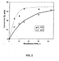
- Fig. 2 shows a graph with comparative data for conversion between a conventional FCC process and the process of the present invention.
- Fig. 3 shows a graph with comparative data for the results obtained for aromatics content in the fraction of middle distillates between the conventional FCC process and the process of the present invention.
- Fig. 1 shows a simplified schematic representation of the present invention, comprising a dense-bed FCC unit into which a feed A is injected at the bottom of the riser (1) of the dense-bed FCC unit.
- a FCC dense-bed reactor is a FCC catalyst fluid bed reactor, in which the superficial velocity of the fluid is lower than in conventional FCC reactors.
- the fluid velocity might be around 0.6 m/s in a FCC dense-bed reactor, but around 20 to 40 m/s (approximately 50 times faster) in a conventional FCC reactor.
- the FCC dense-bed reactor of the present invention is run with a superficial velocity of less than 15 m/s, more preferably less than 10 m/s and even more preferably less than 5 m/s.
- Feed A consists of fractions of the HVGO or ATR type, or a mixture of the two in any proportions.
- the Feed A is injected at a controlled injection temperature in the range from 150°C to 300°C.
- the reaction temperature is controlled in the range from 500°C to 580°C, preferably 520°C to 560°C, more preferably between 535°C to 545°C and most preferably maintained around 540°C.
- the mixture of hydrocarbons and catalyst travels through the riser (1) and is discharged into the dense-bed FCC reactor (2), where the cracking reactions continue in the dense bed.
- the catalyst/oil mass ratio in the reactor varies in the range from 8 to 15, preferably 10, and the contact time between the catalyst and the hydrocarbons in the assembly of riser (1) and dense-bed FCC reactor (2) can vary between 30 and 120 seconds, but should preferably be maintained in the range from 70 to 90 seconds.
- the contact time between the catalyst and the feed is determined by the flow rates of the feed and the catalyst and the size of the apparatus section (i.e. the length of the flow path) in which the catalyst and the feed contact each other.
- the catalyst flows directly to the rectifier (3) in the annular region of the lower portion of the vessel and from there, following steam rectification, the catalyst is sent to the regenerator, through a pipe (4).
- the level of the catalyst bed in reactor (2) is controlled by a valve (5).
- the catalyst from the regenerator is recycled to the riser (1) via a pipe (7), the flow of catalyst in pipe (7) being controlled by a valve (8).
- the dense-bed FCC reactor (2) produces an effluent B, which, after fractionation in the fractionating tower (9), generates a gas fraction C, which is sent to the gas recuperation section, a light naphtha D which, after it has been desulphurized, can be sold as petrochemical naphtha, a middle distillate of low aromaticity E which, after desulphurization, can be incorporated in the diesel pool, and a bottom product F, normally intended for fuel oil.
- the temperature of the catalyst in the rectifier (3) is around 540°C, allowing rectification of high efficiency and eliminating the drawbacks of rectification at low severity.
- the temperature of the bed in the regenerator (6) is preferably adjusted to a temperature range from 685°C to 710°C, by appropriate control of the temperature of the feed for the dense-bed reactor in the range from 150°C to 300°C.
- the invention also includes another aspect that relates to the use of a low-activity cracking catalyst of reduced acidity, or of basic character, that minimizes the production of aromatics in comparison with conventional FCC catalysts.
- the low catalytic activity of the catalyst is characterized in that it would provide conversions of typical FCC feeds of, at most, 40% at a catalyst/oil mass ratio of about 10, reaction temperature of 540°C and contact time between feed and catalyst of less than 10 seconds.
- the catalyst recommended in the present invention preferably has a low concentration or is preferably free from acidic zeolites in the protic form or exchanged with rare earths, which are usually employed as the main active ingredient of existing FCC catalysts.
- the catalytic composition suitable for the invention may include the other components of the matrix of an FCC catalyst such as oxides and hydroxides of aluminium and/or silicon, as well as clays to impart suitable physical properties to the catalyst.
- the acidity and activity of such components can be ajusted by lixiviation and/or doping with alkali metals, alkaline earths, trivalent metals or transition metals.
- other materials with basic characteristics or of low protic acidity such as hydroxides and oxides of transition metals, mixed derivatives of hydroxides and oxides, cationic and anionic clays, phosphates, hydroxy-phosphates and silica-alumina phosphates, doped or treated thermally and/or chemically, can also constitute or be incorporated in the catalytic composition required for the invention.
- hydroxides and oxides of transition metals mixed derivatives of hydroxides and oxides, cationic and anionic clays, phosphates, hydroxy-phosphates and silica-alumina phosphates, doped or treated thermally and/or chemically
- the catalyst of the present invention promotes the formation of saturated hydrocarbons to the detriment of aromatics, as its low activity is compensated by a longer contact time between the catalyst and feed during the cracking reaction without significantly promoting an increase in the aromatics content of the products.
- catalysts with an increased basic character or catalysts with a reduction of protonic acidity are preferable.
- Some of the catalytic materials suitable for use with this invention may have both characteristics. That is, they may be amphoteric (functioning as either a base or an acid) or they may be solid oxides with protonic acidity doped with elements that reduce their acidity (either by reducing the number of catalytic sites or their catalytic strength) and/or generate basic sites.
- the basicity of catalysts tested for use in the present invention was measured by temperature programmed CO 2 desorption monitored by mass spectrometry (TPD/MS-CO 2 ). The tests were conducted in a TPD/MS equipment.
- Samples were pre-heated in-situ at 5°C/min up to 600°C under helium flow and kept at this temperature for an hour. After this, the sample was cooled down to room temperature. Then, CO 2 flow was admitted to the chamber to allow adsorption for another hour. At that point, the CO 2 flow was interrupted and a helium flow was used in order to eliminate the CO 2 physically adsorbed.
- the temperature was raised up to 450°C at a heating-up rate of 20°C/min while recording desorption of the chemisorbed CO 2 .
- the desorption was expressed in units of micromoles of CO 2 per gram of catalyst. It was found that preferred catalysts for use with the present invention had a basicity of at least 50 micromoles of CO 2 /g, and more preferably at least 100 micromoles of CO 2 /g in the aforementioned determination conditions.
- the protic acidity of catalysts tested for use in the present invention was measured by the following method.
- the catalyst was pre-treated under 100% steam flow at 788°C for 5 hours in a fixed bed steamer in order to simulate hydrothermal deactivation of the catalyst in the regenerator of an FCC unit.
- the protic acidity (the Brönsted acidity) was determined by using temperature-programmed desorption of n-propylamine in a TPD/TPR 2900 Micromeritics instrument coupled with a mass spectrometer, according to the method described by O. Kresnawahjuesa et alli in Catal. Letters 82 (2002) 155 . According to this method, N-propylamine saturated onto the catalyst desorbs without reaction up to ⁇ 300°C. However, at higher temperatures the adsorption complex formed at the Brönsted acid sites decomposes into ammonia and propylene, which is quantified and represent a measurement of the relative Brönsted acidity.
- preferred catalysts for use with the present invention had a protic acidity of no more than 50 micromoles of propylene per gram of catalyst, and more preferably no more than 15 micromoles of propylene/g, in the aforementioned determination conditions (including the step of the hydrothermal deactivation).
- Tests were conducted in a fluidized-bed unit, that comprised a stirred reactor of the CREC type (of LASA, H. I. (1992) - US 5,102,628 ), suitable for kinetic studies and that permitted, by its design characteristics, operation with extended residence times.
- the catalyst was charged in the reaction chamber and kept fluidized with ascending motion by an impeller rotating at high speed. When the reactor was at the desired reaction conditions the feed was injected. After the required reaction time was reached, the products are discharged and analysed by gas chromatography. A constant catalyst/feed ratio of about 10 was used in the experiments presented here.
- catalyst "B” a mixed aluminium-magnesium oxide with basic characteristics and relatively low cracking activity, at the reaction temperature typical of conventional FCC, 540°C.
- the system recommended in the present invention is able to reach levels of conversion similar to those of the reference case, as well as similar yields of middle fractions.
- the resultant aromatics content in the middle fractions (C 10 -C 11 ) is significantly lower in the case of the system recommended for the present invention, thus demonstrating the clear advantage of the process of the invention.
- the present invention improves the Cetane number of FCC mid-distillates.
- the actual values of the Cetane number obtained depend on the feed quality. Higher Cetane mid-distillates can be produced with more parafinic fees (ie. with a high API).
- Mid-distillate Cetane number is also a function of conversion; the higher the conversion the lower the Cetane number.
- Table 2 illustrates the ranges of Cetane numbers obtained for two different VGO qualities at the same conversion. TABLE 1 MARLIN - REPLAN PETROLEUM RESULTS Density at 20/4°C 0.9519 °API 16.5 Viscosity at 60°C (ASTM D 455); cSt.
Landscapes
- Chemical & Material Sciences (AREA)
- Oil, Petroleum & Natural Gas (AREA)
- Engineering & Computer Science (AREA)
- Chemical Kinetics & Catalysis (AREA)
- General Chemical & Material Sciences (AREA)
- Organic Chemistry (AREA)
- Production Of Liquid Hydrocarbon Mixture For Refining Petroleum (AREA)
- Catalysts (AREA)
Abstract
Description
- The present invention relates to a process and equipment for fluid catalytic cracking (FCC), for the production of middle distillates of low aromaticity, in the absence of added hydrogen, from heavy hydrocarbon feedstocks of various origins.
- The invention further relates to FCC equipment for the production of the above products.
- The purpose of the FCC process is to convert liquid hydrocarbons of high molecular weight, which generally have an Initial Boiling Point (IBP) in the range from 320°C to 390°C, or higher, and typical densities in the range from 8 to 28°API, such as oil refinery effluents produced from side cuts from vacuum towers, called heavy vacuum gas oil (HVGO), or from the bottom of atmospheric towers, called atmospheric residue (ATR), or mixtures of these effluents, to light hydrocarbon fractions such as gasoline (IBP around 30°C) and liquefied petroleum gas (LPG) (maximum vapour pressure of 15 kgf/cm2 at 37.8°C).
- The stages of the FCC process are well known by a person skilled in the art and are described in various patent documents. The process described in Brazilian patent
PI 9303773-2 - Despite the long existence of the FCC process, there is a constant search for ways of improving the process, by increasing the production of derivatives of greater added value, such as gasoline and LPG. In general, it can be said that the main aim of the FCC processes is maximization of the output of these higher-value derivatives.
- Maximization of said higher-value derivatives is obtained, basically, in two ways. Firstly, by increasing the so-called "conversion", which corresponds to reduction of the output both of heavy products (clarified oil), and of light cycle oil (LCO). Secondly, by lowering the yields of coke and fuel gas, i.e. by lower "selectivity" of the process with respect to said higher-value derivatives.
- The lower output of fuel gas and coke, on increasing the selectivity of the process for LPG and gasoline, has as additional beneficial consequences, the use of smaller air blowers and wet gas compressors, large machines with high energy consumption, and in general limiting the capacity of the FCC units. Moreover, it is economically advantageous to promote increases in products of higher added value.
- An important aspect to consider is the possible benefit or need to increase the production of LPG in accordance with the refiner's needs.
- It is well known by a person skilled in the art that an important aspect of the process is the initial contact of the catalyst with the feed, which has a decisive influence on the conversion and the selectivity of the process by generating high-value products. In the FCC process, the preheated hydrocarbon feed is injected near the bottom of a conversion zone or "riser", where it comes in contact with the stream of regenerated catalyst, from which it receives a sufficient amount of heat to vaporize it and supply the requirements of the endothermic reactions that predominate in the process.
- The riser is a long vertical pipe having dimensions in industrial units of about 0.5 m to 2.0 m in diameter, with a height of 25-40 m, where chemical reactions take place.
- After the riser, the spent catalyst, with coke deposited on its surface and in its pores, is separated from the reaction products and sent to the regenerator for burning the coke to restore its activity and to generate heat which, transferred by the catalyst to the riser, will be utilized by the process.
- The conditions prevailing at the point of introduction of the feed in the riser are decisive for the products that form in the reaction. In this region there is the initial mixing of the feed with the regenerated catalyst, heating of the feed up to the boiling point of its components and vaporization of the major portion of these components. The typical total residence time of the hydrocarbons in the riser is about 1 to 4 seconds.
- For the reactions of catalytic cracking to take place, it is necessary for the vaporization of the feed in the region of mixing with the catalyst to take place rapidly. This is so that the vaporized hydrocarbon molecules can come in contact with the catalyst particles, whose size is about 70 micrometres, permeate through the mesopores and micropores of the catalyst, and react in the acid sites. Failure to achieve this rapid vaporization results in thermal cracking of the liquid fractions of the feed.
- It is known that thermal cracking promotes the formation of by-products such as coke and fuel gas, principally in the cracking of residual feeds. The coke poisons the acid sites and may eventually block the pores of the catalyst. Therefore thermal cracking at the bottom of the riser competes undesirably with catalytic cracking, the purpose of the process.
- Optimization of the conversion of the feed usually requires maximum removal of the coke from the catalyst in the regenerator. Combustion of the coke can take place in conditions of partial combustion or complete combustion.
- In partial combustion, the gases produced by the combustion of the coke are mainly constituted of CO2, CO and H2O and the content of coke in the regenerated catalyst is of the order of 0.1 to 0.3 wt.%. In complete combustion, carried out in the presence of a greater excess of oxygen, practically all the CO produced in the reaction is converted to CO2.
- The reaction of oxidation of CO to CO2 is highly exothermic, with the result that complete combustion takes place with considerable release of heat, leading to very high regeneration temperatures. Complete combustion produces catalyst containing less than 0.1 wt.% % and, preferably less than 0.05 wt.% of coke, and is, in this respect, more advantageous than partial combustion, making up for a lower catalyst/oil mass ratio. The explanation for this fact is that complete combustion favours the regeneration of the catalyst and makes it more active, as well as avoiding the use of an expensive boiler for subsequent combustion of the CO.
- The increase in coke in the spent catalyst results in an increase in combustion of coke in the regenerator per unit of mass of circulating catalyst. In conventional FCC units, the heat is removed from the regenerator via the combustion gas and more effectively by the stream of hot regenerated catalyst. An increase in the content of coke on the spent catalyst increases the temperature of the regenerated catalyst and the temperature difference between the regenerator and the reactor.
- Therefore, a reduction in the flow of regenerated catalyst to the reactor, usually called catalyst circulation rate, is desirable in order to meet the thermal demand of the reactor and maintain the same reaction temperature. However, the lower catalyst circulation rate required by the larger temperature difference between the regenerator and the reactor results in reduction of the catalyst/oil ratio, decreasing the conversion, but also decreasing the deposition of coke on the catalyst, in contrast to the initial effect of increase in the content of coke.
- Thus, the circulation of catalyst from the regenerator to the reactor is determined by the thermal demand of the riser and by the temperature that is established in the regenerator, which depends on the production of coke. As the coke produced in the riser is affected by said circulation of catalyst, it is concluded that the process of catalytic cracking functions in conditions of thermal balance, and, for the reasons stated, operation at very high regeneration temperature is undesirable.
- As a rule, with the modern FCC catalysts, the temperatures of the regenerator, and therefore of the regenerated catalyst, are kept below 760°C, preferably below 732°C, as the loss of activity would be very severe above this value. The desirable operating range is from 685°C to 710°C. The lower value is dictated primarily by the need to ensure proper combustion of the coke.
- With the processing of heavier and heavier feeds, there is a tendency for the production of coke to increase and operation with complete combustion requires the installation of catalyst coolers to keep the temperature of the regenerator within acceptable limits. Generally, the catalyst coolers remove heat from a catalyst stream from the regenerator, returning a substantially cooled catalyst stream to this vessel.
- Various works in the patent literature propose injecting auxiliary streams, such as water or other petroleum fractions, in the risers at a point above the point of injection of the principal feed to be cracked, with the objective of promoting an increase in mixture temperature in the region of feed injection, aiming to increase the percentage of the residual feeds vaporized, without altering the outlet temperature of the riser.
- This approach is described in
US patent 4,818,372 , which discloses an apparatus for FCC with temperature control that includes an ascending or descending reactor, device for introducing the hydrocarbon feed under pressure and in contact with a regenerated cracking catalyst, and at least one device for injecting an auxiliary fluid downstream of the reactor zone where the feed and the catalyst come in contact, by which it is claimed that a higher temperature is reached in the region of mixing of the feed with the catalyst. This patent uses an inert external fluid whose main effect is cooling of the region of injection of said fluid, with temperature control and increase in circulation of the catalyst. - According to the teaching in
US patent 4,818,372 , an external stream is injected separately at an upper point of the riser for the purpose of controlling the temperature profile of the latter, so as to maintain the initial section of the riser at a relatively higher temperature without altering the temperature of the top of the riser (reaction temperature or TRX). This control can also be achieved by recycling heavy naphtha, as taught inUS patent 5,087,349 . - With this same objective,
US patent 5,389,232 teaches recycling of heavy naphtha at upper points of the riser. -
US patent 4,764,268 suggests injecting a stream of LCO at the top of the riser with the aim of minimizing reactions of overcracking of naphtha. - A similar alternative, taught in
US patent 5,954,942 , aims at an increase in conversion, by "quenching" or rapid cooling with an auxiliary stream of steam in the upper region of the riser. - Publication
WO 93/22400 - Bearing in mind the increase in demand for high-quality middle distillates, to the detriment of the market for gasoline, which is the main product of conventional FCC, changes in the mode of operation of the FCC unit have been discussed, with the aim of increasing the output of LCO. Several technical articles discuss changes to the catalytic system and to the process variables, so as to achieve a reduction in the process severity, for the purpose of increasing the yield of middle fractions and reducing the content of aromatics in the middle fractions. The following are included, among the operating conditions:
- reduction of the reaction temperature;
- reduction of the catalyst/oil ratio;
- reduction of catalytic activity.
- All these measures aim to reduce the conversion, with consequent increase in the output of decanted oil.
- Some important references on this subject are listed below.
- a) "Distillate yield from the FCC: process and catalyst changes for maximization of LCO", Catalysts Courier, R. W. PETERMAN;
- b) Hydrocarbon Publishing Company 2004, "Advanced Hydrotreating and hydrocarbon technology to produce ultra 2-clean diesel fuel";
- c) "Studies on maximizing diesel oil production from FCC", Fifth international symposium on the advances in fluid catalytic cracking, (218th National meeting, American Chemical Society, 1999);
- d) "New development boosts production of middle distillate from FCC", Oil and Gas Journal (August, 1970)".
- LCO is one of the by-products of the FCC, representing from 15% to 25% of the yield and corresponding to the distillation range typically between 220°C and 340°C. Normally the LCO has a high concentration of aromatics, even exceeding 80 wt.% of the total hydrocarbons present in said LCO fraction. In some situations it is beneficial to operate the FCC in such a way as to maximize the stream of LCO, and in this case it is desirable to incorporate the LCO in the pool of diesel oil. The high concentration of aromatics in LCO means that it has very poor knock characteristics in diesel engines (low cetane number) and high density. The high aromatics content also makes it difficult to improve its properties by hydrofining or desulphurization.
- In the commonest form of operation for maximizing middle fractions in FCC, the reaction temperature is reduced to extremely low values (from 450°C to 500°C), circulation of catalyst is minimized and a catalyst of low activity is used. All these measures increase the yield and improve the quality (lower the aromatics content) of the LCO produced. The problem with this type of operation is that at the same time it promotes an increase in the residual fraction (340°C+ cut) in FCC, normally used for low-value fuel oil.
- Operation at low temperatures in the post-riser region, which is a consequence of the low reaction temperature, as well as impairing the rectification efficiency of the catalyst, has the result that heavy fractions of the FCC product condense on the surface of the walls and internals of the reactor, leading to formation of coke on the walls of the separating vessel. The phenomenon of coke formation is a characteristic of reactors equipped with rapid separation systems, chiefly in units that process heavy feeds. The formation of coke from fine films of condensate continues throughout the campaign of the unit, and commonly, at the end there are several tonnes of coke occupying a large proportion of the interior of the separating vessel.
- This coke formation presents a serious risk of ignition and so must be removed completely before starting maintenance work on the unit, causing important losses for the refiner, owing to the delay in the timetable resulting from said removal. There is also the possibility of falling of this coke that has formed inside the separating vessel, during the campaign, which tends to block the flow of the catalyst, often leading to unscheduled shutdown of the unit. In both cases it causes loss of revenue.
-
US patent 6,416,656 teaches a process for simultaneously increasing the yield of diesel and LPG. In this process, the gasoline is recracked to increase the yield of LPG, being injected at a point below the feed nozzle. The process feed is injected at multiple points along the riser, reducing the contact time and hence increasing the yield of LCO. However, the reduced severity of the FCC riser for middle distillates means that the cracking of naphtha in these conditions is not very effective. - Examination of the references cited shows that the literature neither discloses nor suggests, separately or in combination, the system and process characteristics resulting from the research conducted by the applicant, which led to the elaboration of the present application.
- Advantageously, and differently from the prior art, the use of a reactor operating with long catalyst-oil contact time endows the invention with the possibility of producing a middle distillate of low aromaticity, while operating the industrial unit at conventional FCC temperatures. This avoids all the problems arising from operation at low temperatures. Moreover, there is a result of conversion of bottoms similar to the values found in industrial units that operate with high values of process conversion. Even better results are achieved using a dense-bed reactor combined with catalysts of low acidity or basic character.
- More specifically, the invention relates to a process of catalytic cracking that preferably employs catalytic systems of lower activity than that of the conventional catalytic systems, of reduced acidity or of basic character, that promote reaction mechanisms that modify the composition of the feed, converting it to lighter hydrocarbons, and making it possible to increase the production of saturated hydrocarbons in the cracked products. These catalytic systems are employed in a special reaction system and in appropriate operating conditions, so as to reach levels of conversion similar to those attained in the conventional processes of catalytic cracking and, at the same time, minimize the generation of aromatic hydrocarbons in the products.
- Application of this process makes it possible to obtain a middle distillate of aromaticity below 5 wt.%, of C10/C11 aromatics, and therefore with suitable characteristics for incorporation in the diesel pool, after hydrofinishing or desulphurization.
- For realization of this objective, a dense-bed FCC reactor is preferably used, which provides long contact times in the risers, in comparison with the conventional FCC process, in which the reactor has entrained-bed fluid dynamics. This guarantees a process conversion level similar to the levels processed in conventional FCC units, which use high-activity catalysts based on zeolite Y.
- However, the big difference is the reduced production of aromatic hydrocarbons in the products with application of this invention. As a result of combining the suitable catalytic system and the proposed process configuration, there is production of a stream of middle distillates with cetane number about 15 points higher than the typical cetane number of the LCO fractions produced in conventional FCC units and having a boiling point range similar to that of diesel. Moreover, the process produces a gasoline that can be used as petrochemical naphtha, after desulphurization.
- The present invention offers solutions to a number of problems arising from the operation of FCC at low severity, as it operates with reaction temperatures similar to those employed in conventional FCC processes.
- In accordance with the concept of the invention, conditions of low severity mean a reaction temperature in the range from 460°C to 520°C. In the case of heavy feeds, this range of reaction temperature results in a marked loss of rectification efficiency, with significant effects on the entrainment of hydrocarbons to the regenerator, and therefore on the heating of the latter.
- In addition to this effect, there is the low thermal demand of the riser, resulting at a catalyst/oil mass ratio in the range from 3.0 to 6.0, increasing the output of decanted oil, along with cumulative increase in the temperature of the regenerator.
- In the present invention, the reactor operates at temperatures normally employed in FCC units, increasing the process severity on the basis of the contact time and the catalyst/oil ratio. On combining this process conception with catalysts of low activity with reduced acidity or with basic character, it is possible to operate with high conversions and products with low aromaticity.
- The stage of rectification of the spent catalyst, for removal of the residual hydrocarbons, has an efficiency similar to that achieved in conventional FCC units, since there is no need to operate the unit with moderate temperatures to reduce the severity.
- Accordingly, the technique envisages a process for catalytic cracking of heavy feeds, in the absence of added hydrogen, using a dense-bed reactor, that operates with high catalyst/oil mass ratio and long contact times, producing a middle distillate of low aromaticity and low yield of decanted oil.
- Said process employs catalysts that promote cracking reactions, while partially inhibiting the formation of aromatic molecules in the lighter products resulting from the reaction.
-
WO 2007/082629 , is also concerned with the purpose of maximization of LCO and reduction of aromatics in the products generated in the FCC process, describes the use of catalysts which, on the basis of their characteristics, could be applied in the present invention. However, in said published patent, the process preferably takes place in two stages, where the first stage employs mild operating conditions of low severity and the second uses conventional zeolitic FCC catalyst. Accordingly, to achieve high conversion in the process it is necessary to install two FCC units with conventional hardware, i.e. with cracking reactions in risers. - In contrast to the aforementioned publication, the present invention provides a process that performs the entire conversion in a single stage, preferably based on the use of a dense-bed reactor. Furthermore, the operating conditions adopted are considered to be of high severity in comparison with the processes that maximize middle distillates, as the proposed invention employs high catalyst/oil mass ratios and extremely long contact times.
- Accordingly, the present invention proposes an alternative that is economically more attractive and gives excellent results in terms of yield and quality, according to the example given in the document. To summarize, the proposed invention envisages the use of only one catalytic system of low activity in a process with only one stage operating with an extended contact time, a combination not foreseen in the literature.
- The overall result of the process according to the present invention is an increase in the yield of middle distillates of low aromaticity and petrochemical naphtha, said process and equipment used for carrying out said process being described and claimed in the present application.
- According to a first aspect of the present invention there is provided a process of fluid catalytic cracking using a reactor for production of middle distillates of low aromaticity from a feed comprising heavy hydrocarbons, the process comprising: contacting the feed with a cracking catalyst for a time of at least 30 seconds.
- In existing FCC processes, the contact time between the cracking catalyst and the feed is about 1 to 4 seconds. The present invention allows for longer residence times under typical FCC conditions, without increasing the residual fraction (340°C + cut) in the FCC products, normally used for low-value fuel oil. The invention produces a middle distinate of low aromoticity.
- Preferably, the processor fluid catalytic cracking uses a dense-bed reactor. A dense bed reactor has a lower superficial fluid velocity than conventional FCC reactors.
- Preferably, the feed is contacted with the cracking catalyst for a time of no more than 120 seconds. Contacting the catalyst and the feed for less than 120 seconds minimises the amount of fuel gas produced in the reactor. It is economically advantageous to promote increases in products of higher value in preference to the production of fuel gas. Further, this has additional process benefits such as allowing the use of smaller airblowers and wear gas compressors.
- Preferably, the feed is contacted with the cracking catalyst for a time in the range of from 70 seconds to 90 seconds. This range of times provides a desirable balance between allowing sufficient cracking to produce the desired product, without the over-production of fuel gas.
- Preferably, the processor fluid catalystic cracking further comprises performing the catalytic cracking at a reaction temperature in the range of from 500°C to 580°C, preferably from 520°C to 560°C, more preferably from 530°C to 550°C and even more preferably from 535°C to 545°C. These temperature ranges allow a suitable severity of reaction to maintain reaction efficiency, without resulting in the deactivation of the catalysts. In present FCC reactors which are optimised for maximising the middle fractions, reaction temperature to extremely low values (e.g. 450°C) which promotes an increase in the fuel oil fraction of the FCC product. The fuel oil is of low economic value, and the present invention avoids the over production of fuel oil.
- Preferably, the processor fluid catalystic cracking further comprises performing the catalytic cracking at a catalyst/oil mass ratio in the range of from 8-15, preferably 9-13 and more preferably at a catalyst/oil mass ratio of 10. Existing FCC reactors optimised for the production of middle distillates are operated at low temperatures. To accommodate the low thermal demand of the reactor, catalyst (which carries heat) is provided at a slower rate, reducing the catalyst/oil mass ratio undesirably to as low as 3. The present invention allows for higher catalyst/oil mass ratio.
- Preferably, the processor fluid catalytic cracking is performed in the absence of hydrogen.
- Preferably, the processor fluid catalytic cracking uses a cracking catalyst of low activity such that the catalyst would achieve a conversion of the fluid catalytic cracking process feed of at most 40% with a catalyst/oil mass ratio of about 10, a reaction temperature of 540°C and feed-catalyst contact time of less than 10 seconds. The use of a catalyst with a low activity increases the yield of middle fractions, whilst the reducing the content of aromatics in the middle fraction.
- Preferably, the processor fluid catalytic cracking uses a catalyst of reduced acidity or basic character. Such catalysts promote cracking reactions, whilst partially inhibiting the formation of aromatic molecules in the lighter products.
- Preferably the catalysts with a basic character for use in the invention are such that, when measured by temperature programmed CO2 desorption monitored by mass spectrometry (TPD/MS-CO2), they evolve at least 50 micromoles of CO2/g of catalyst, and more preferably at least 100 micromoles of CO2/g. That is, they evolve at least 50 micromoles of CO2/g of catalyst, and more preferably at least 100 micromoles of CO2/g when samples are pre-heated in-situ at 5°C/min up to 600°C under helium flow and kept at this temperature for an hour; then cooled down to room temperature; then CO2 flow is admitted to the chamber to allow adsorption for another hour; and then the CO2 flow is interrupted and a helium flow is used in order to eliminate the CO2 physically adsorbed, whilst the temperature is raised up to 450°C at a heating-up rate of 20°C/min whilst recording desorption of the chemisorbed CO2.
- Preferably, the catalysts with reduced protic acidity for use with the the present invention are such that their protic acidity (the Brönsted acidity) is no more than 50 micromoles of propylene per gram of catalyst, and more preferably no more than 15 micromoles of propylene/g. That is, their protic acidity (the Brönsted acidity) is no more than 50 micromoles of propylene per gram of catalyst, and more preferably no more than 15 micromoles of propylene/g, when determined by using temperature-programmed desorption of n-propylamine in a TPD/TPR 2900 Micromeritics instrument coupled with a mass spectrometer, according to the method described by O. Kresnawahjuesa et al in Catal. Letters 82 (2002) 155, after being pre-treated under 100% steam flow at 788°C for 5 hours in a fixed bed steamer.
- Preferably, the catalyst contains a low concentration, or is preferably free from, acidic zeolites in the protic form on exchanged with rare earths. Catalysts containing acidic zeolites in the protic form or exchanged with rare earths are used in existing FCC reactors. However, such catalysts are not optimised for the production of middle distillates.
- Preferably, the catalyst is formulated with materials that possess basic characteristics, or low protic acidity, such as hydroxides and oxides of transition metals, mixed derivatives of hydroxides or oxides, cationic and anionic clays, phosphates, hydroxy-phosphates and silica-alumina phosphates, doped or treated thermally and/or chemically. Such components improve the zeolite activity of the cracking reaction for the production of middle distillates.
- Preferably, the processor fluid catalytic cracking produces a reaction product with a combined content of C10 and C11 aromatics below 5 wt.%. It is desirable to have a low concentration of aromatics in the reaction product, so that fractions such as LCO are suitable for use in the production of diesel oils.
- According to another aspect of the invention there is provided a fluid catalytic cracking apparatus comprising: a fluid catalytic cracking reactor; wherein the apparatus is constructed and arranged to contact the catalyst and the feed for at least 30 seconds.
- According to this aspect of the invention there is provided an apparatus which can carry out the process of the first aspect.
- Preferably the fluid catalytic cracking apparatus provides flow paths for the feed and the catalyst, and the apparatus is configured to cause the feed and the catalyst to flow along their respective flow paths at flow rates such that the catalyst and the feed contact eachother for at least 30 seconds. That is, the contact time between the catalyst and the feed is determined by the flow rate of the catalyst and feed through the apparatus, in combination with the size of the section of the apparatus through which the catalyst and feed flow whilst they are in contact with each other.
- Preferably the fluid catalytic cracking apparatus comprises a dense bed reactor.
- Preferably the fluid catalytic cracking apparatus further comprises a riser arranged to supply a feed comprising heavy hydrocarbons and a catalyst to the dense-bed fluid catalytic cracking reactor. The catalyst and the feed are contacted in the riser before entering the fluid catalytic cracking reactor.
- Preferably, the fluid catalytic cracking reactor has an outlet for used catalysts and an outlet for the catalytic cracking reaction product. The reaction products can be removed for further separation and processing, whilst the used catalyst is recylcled and regenerated to be re-supplied to the reactor.
- In one embodiment, there is provided a process of fluid catalytic cracking for production of middle distillates of low aromaticity, characterized in that it comprises the following stages:
- a) submitting a feed A, consisting of heavy fractions of hydrocarbons, such as a heavy vacuum gas oil, or an atmospheric residue, or a mixture thereof in any proportions, to a reaction of fluid catalytic cracking, in the absence of added hydrogen, in the riser (1) of a dense-bed FCC reactor (2), operated:
- (i) at temperatures that vary in the range from 520°C to 560°C, preferably around 540°C;
- (ii) using a cracking catalyst of low activity, of reduced acidity or of basic character;
- (iii) at a catalyst/oil mass ratio in the range from 8 to 15, preferably 10, and
- (iv) with a contact time in the range from 30 to 120 seconds, preferably in the range from 70 to 90 seconds;
- b) withdrawing the effluent B obtained in the above reaction at the top of the dense-bed catalytic cracking reactor (2), submitting it to fractionation in a fractionating tower (9) that produces a gas fraction C, which is sent to a gas recuperation section, plus a light naphtha fraction D, and a middle distillate E, both of low aromaticity, and sending these for subsequent treatment and sale.
- In another embodiment, in the process of fluid catalytic cracking for production of middle distillates of low aromaticity the low catalytic activity of the catalyst is limited to a conversion of the FCC feed of at most 40%, under operating conditions typical of FCC with a catalyst/oil mass ratio of about 10, reaction temperature of 540°C and feed-catalyst contact time less than 10 seconds.
- In another embodiment, in the process of fluid catalytic cracking for production of middle distillates of low aromaticity, the following are used as cracking catalysts (i) catalysts having low catalytic activity, reduced acidity or basic character, that contain, moreover, low concentration, or preferably are free from acidic zeolites in the protic form or exchanged with rare earths, in addition being formulated with other components of a matrix typical of an FCC catalyst, such as oxides and hydroxides of aluminium and/or silicon, as well as clays, whose acidity and activity can be ajusted by lixiviation and/or doping with alkali metals, alkaline-earth metals, trivalent metals or transition metals and (ii) the catalysts formulated with other materials that possess basic characteristics, or low protic acidity, such as hydroxides and oxides of transition metals, mixed derivatives of hydroxides or oxides, cationic and anionic clays, phosphates, hydroxy-phosphates and silica-alumina phosphates, doped or treated thermally and/or chemically.
- In another embodiment, in the process of fluid catalytic cracking for production of middle distillates of low aromaticity, the effluent B has contents of aromatics (C10 and C11) below 5 wt.%.
- In another embodiment, there is provided equipment for fluid catalytic cracking for production of middle distillates of low aromaticity according to the process described in the preceding embodiments, characterized in that it comprises a riser (1) ending in a dense-bed FCC reactor (2) that is connected to a rectifier (3), which in its turn is connected to a regenerator (6) via a pipe (4), which is equipped with a valve (5) whose function is to control the level in the dense-bed FCC reactor (2); the catalyst from the regenerator is recycled to the riser (1) through a pipe (7), the flow of catalyst in pipe (7) being controlled by a valve (8).
- The invention also relates to equipment that comprises a riser ending in a dense-bed FCC reactor where a reaction of fluid catalytic cracking is carried out, in the absence of added hydrogen, producing the effluent which, after it has been fractionated in a fractionating tower, generates the middle distillate of low aromaticity which, after it has been desulphurized, can be incorporated in the diesel pool and the naphtha fraction, also of low aromaticity which, after being separated in a stabilizer tower, and desulphurized, can be sold as petrochemical naphtha.
- Additionally, the naphtha fraction can be sent to the conventional FCC unit where it undergoes recracking to produce a high-octane gasoline.
- The FCC process and equipment for production of middle distillates of low aromaticity and high-octane gasoline, according to the present invention, will now be described in detail, by way of example only, based on the diagrams referred to below, which are an integral part of the present specification.
-
Fig. 1 shows a simplified schematic representation of equipment to be used for carrying out the process of the present invention. -
Fig. 2 shows a graph with comparative data for conversion between a conventional FCC process and the process of the present invention. -
Fig. 3 shows a graph with comparative data for the results obtained for aromatics content in the fraction of middle distillates between the conventional FCC process and the process of the present invention. - The FCC process for production of middle distillates of low aromaticity according to the present invention; will be described in detail referring to the diagrams, according to the identification of the respective components.
-
Fig. 1 shows a simplified schematic representation of the present invention, comprising a dense-bed FCC unit into which a feed A is injected at the bottom of the riser (1) of the dense-bed FCC unit. - A FCC dense-bed reactor is a FCC catalyst fluid bed reactor, in which the superficial velocity of the fluid is lower than in conventional FCC reactors. For example, for a catalyst with an average particle size of 70 microns, the fluid velocity might be around 0.6 m/s in a FCC dense-bed reactor, but around 20 to 40 m/s (approximately 50 times faster) in a conventional FCC reactor. Preferably, the FCC dense-bed reactor of the present invention is run with a superficial velocity of less than 15 m/s, more preferably less than 10 m/s and even more preferably less than 5 m/s.
- Feed A consists of fractions of the HVGO or ATR type, or a mixture of the two in any proportions. The Feed A is injected at a controlled injection temperature in the range from 150°C to 300°C. The reaction temperature is controlled in the range from 500°C to 580°C, preferably 520°C to 560°C, more preferably between 535°C to 545°C and most preferably maintained around 540°C. The mixture of hydrocarbons and catalyst travels through the riser (1) and is discharged into the dense-bed FCC reactor (2), where the cracking reactions continue in the dense bed. The catalyst/oil mass ratio in the reactor varies in the range from 8 to 15, preferably 10, and the contact time between the catalyst and the hydrocarbons in the assembly of riser (1) and dense-bed FCC reactor (2) can vary between 30 and 120 seconds, but should preferably be maintained in the range from 70 to 90 seconds.
- The contact time between the catalyst and the feed is determined by the flow rates of the feed and the catalyst and the size of the apparatus section (i.e. the length of the flow path) in which the catalyst and the feed contact each other.
- From the vessel of the dense-bed FCC reactor (2), the catalyst flows directly to the rectifier (3) in the annular region of the lower portion of the vessel and from there, following steam rectification, the catalyst is sent to the regenerator, through a pipe (4). The level of the catalyst bed in reactor (2) is controlled by a valve (5). The catalyst from the regenerator is recycled to the riser (1) via a pipe (7), the flow of catalyst in pipe (7) being controlled by a valve (8).
- In these conditions the dense-bed FCC reactor (2) produces an effluent B, which, after fractionation in the fractionating tower (9), generates a gas fraction C, which is sent to the gas recuperation section, a light naphtha D which, after it has been desulphurized, can be sold as petrochemical naphtha, a middle distillate of low aromaticity E which, after desulphurization, can be incorporated in the diesel pool, and a bottom product F, normally intended for fuel oil.
- The temperature of the catalyst in the rectifier (3) is around 540°C, allowing rectification of high efficiency and eliminating the drawbacks of rectification at low severity.
- The temperature of the bed in the regenerator (6) is preferably adjusted to a temperature range from 685°C to 710°C, by appropriate control of the temperature of the feed for the dense-bed reactor in the range from 150°C to 300°C.
- The invention also includes another aspect that relates to the use of a low-activity cracking catalyst of reduced acidity, or of basic character, that minimizes the production of aromatics in comparison with conventional FCC catalysts. The low catalytic activity of the catalyst is characterized in that it would provide conversions of typical FCC feeds of, at most, 40% at a catalyst/oil mass ratio of about 10, reaction temperature of 540°C and contact time between feed and catalyst of less than 10 seconds.
- The catalyst recommended in the present invention preferably has a low concentration or is preferably free from acidic zeolites in the protic form or exchanged with rare earths, which are usually employed as the main active ingredient of existing FCC catalysts. The catalytic composition suitable for the invention may include the other components of the matrix of an FCC catalyst such as oxides and hydroxides of aluminium and/or silicon, as well as clays to impart suitable physical properties to the catalyst. The acidity and activity of such components can be ajusted by lixiviation and/or doping with alkali metals, alkaline earths, trivalent metals or transition metals.
- Optionally, other materials with basic characteristics or of low protic acidity such as hydroxides and oxides of transition metals, mixed derivatives of hydroxides and oxides, cationic and anionic clays, phosphates, hydroxy-phosphates and silica-alumina phosphates, doped or treated thermally and/or chemically, can also constitute or be incorporated in the catalytic composition required for the invention. However, it is preferable to avoid the presence of components that promote dehydrogenating activity. The catalyst of the present invention promotes the formation of saturated hydrocarbons to the detriment of aromatics, as its low activity is compensated by a longer contact time between the catalyst and feed during the cracking reaction without significantly promoting an increase in the aromatics content of the products.
- According to the present invention, catalysts with an increased basic character or catalysts with a reduction of protonic acidity are preferable. Some of the catalytic materials suitable for use with this invention may have both characteristics. That is, they may be amphoteric (functioning as either a base or an acid) or they may be solid oxides with protonic acidity doped with elements that reduce their acidity (either by reducing the number of catalytic sites or their catalytic strength) and/or generate basic sites.
- The basicity of catalysts tested for use in the present invention was measured by temperature programmed CO2 desorption monitored by mass spectrometry (TPD/MS-CO2). The tests were conducted in a TPD/MS equipment.
- Samples were pre-heated in-situ at 5°C/min up to 600°C under helium flow and kept at this temperature for an hour. After this, the sample was cooled down to room temperature. Then, CO2 flow was admitted to the chamber to allow adsorption for another hour. At that point, the CO2 flow was interrupted and a helium flow was used in order to eliminate the CO2 physically adsorbed.
- Under He flow, the temperature was raised up to 450°C at a heating-up rate of 20°C/min while recording desorption of the chemisorbed CO2.
- The desorption was expressed in units of micromoles of CO2 per gram of catalyst. It was found that preferred catalysts for use with the present invention had a basicity of at least 50 micromoles of CO2/g, and more preferably at least 100 micromoles of CO2/g in the aforementioned determination conditions.
- The protic acidity of catalysts tested for use in the present invention was measured by the following method.
- The catalyst was pre-treated under 100% steam flow at 788°C for 5 hours in a fixed bed steamer in order to simulate hydrothermal deactivation of the catalyst in the regenerator of an FCC unit.
- The protic acidity (the Brönsted acidity) was determined by using temperature-programmed desorption of n-propylamine in a TPD/TPR 2900 Micromeritics instrument coupled with a mass spectrometer, according to the method described by O. Kresnawahjuesa et alli in Catal. Letters 82 (2002) 155. According to this method, N-propylamine saturated onto the catalyst desorbs without reaction up to ∼300°C. However, at higher temperatures the adsorption complex formed at the Brönsted acid sites decomposes into ammonia and propylene, which is quantified and represent a measurement of the relative Brönsted acidity.
- It was found that preferred catalysts for use with the present invention had a protic acidity of no more than 50 micromoles of propylene per gram of catalyst, and more preferably no more than 15 micromoles of propylene/g, in the aforementioned determination conditions (including the step of the hydrothermal deactivation).
- The present invention will now be illustrated with an example, which should not, however, be regarded as limiting it, but only has the aim of demonstrating the effectiveness of the invention.
- A conventional zeolitic catalyst designated "A" and another non-zeolitic catalyst of low activity designated "B", as recommended in the present invention, underwent comparative tests using gas oil feed typical of Brazilian petroleum (Table 1). Tests were conducted in a fluidized-bed unit, that comprised a stirred reactor of the CREC type (of
LASA, H. I. (1992) - US 5,102,628 ), suitable for kinetic studies and that permitted, by its design characteristics, operation with extended residence times. The catalyst was charged in the reaction chamber and kept fluidized with ascending motion by an impeller rotating at high speed. When the reactor was at the desired reaction conditions the feed was injected. After the required reaction time was reached, the products are discharged and analysed by gas chromatography. A constant catalyst/feed ratio of about 10 was used in the experiments presented here. - A conventional FCC catalyst "A", suggested by the manufacturer for operation to maximize middle fractions (LCO) in the FCC process, was tested at a temperature of 480°C. This temperature corresponds to that recommended for this application, being lower than the temperature employed in normal operation of greater severity for maximization of gasoline. This is the reference case.
- The case that is intended as an example of the scope of the present invention used catalyst "B", a mixed aluminium-magnesium oxide with basic characteristics and relatively low cracking activity, at the reaction temperature typical of conventional FCC, 540°C.
- As can be seen from
Fig. 2 , on applying the sufficient residence time, the system recommended in the present invention is able to reach levels of conversion similar to those of the reference case, as well as similar yields of middle fractions. However, as shown inFig. 3 , for the same conversion or the same yield of bottoms/residue, the resultant aromatics content in the middle fractions (C10-C11) is significantly lower in the case of the system recommended for the present invention, thus demonstrating the clear advantage of the process of the invention. - The present invention improves the Cetane number of FCC mid-distillates. The actual values of the Cetane number obtained depend on the feed quality. Higher Cetane mid-distillates can be produced with more parafinic fees (ie. with a high API). Mid-distillate Cetane number is also a function of conversion; the higher the conversion the lower the Cetane number. Table 2 illustrates the ranges of Cetane numbers obtained for two different VGO qualities at the same conversion.
TABLE 1 MARLIN - REPLAN PETROLEUM RESULTS Density at 20/4°C 0.9519 °API 16.5 Viscosity at 60°C (ASTM D 455); cSt. 107 Viscosity at 82.2°C (ASTM D 455), cSt. 35.06 Viscosity at 100°C (ASTM D 455), cSt. 17.72 Refractive index at 70°C (ASTM D 1774) 1.5135 Sulphur (ASTM D 5354), ppm 7116 Distillation (ASTM D 97) °C IBP 291.1 5% 355.8 10% 381.4 30% 430.5 50% 460.6 70% 493.7 90% 535.3 95% 555.8 FBP 621.1 Ramsbottom Carbon Residue (ASTM D 524), wt.% 1.23 Aniline point (ASTM D 611) °C 72.5 Total Nitrogen (Antek), ppm 3246 Basic Nitrogen (UOP 269), ppm 1307 HPLC/SFC, wt.% Saturated compounds 51.1 Monoaromatics 18.3 Diaromatics 18.9 Triaromatics 8.1 Polyaromatics 3.6 TABLE 2 Feed 1 Feed 2Feed API 30 30 19 19 Conversion (to products boiling below 350°C and coke), wt% 15 15 20 20 Mid Distillate (221-343°C) Cetane number 20-25 35-40 20-25 30-35
Claims (17)
Applications Claiming Priority (1)
| Application Number | Priority Date | Filing Date | Title |
|---|---|---|---|
| BRPI0800236-3A BRPI0800236B1 (en) | 2008-01-24 | 2008-01-24 | FLUID CATALYTIC CRACKING PROCESS AND EQUIPMENT FOR THE PRODUCTION OF LOW AROMATIC MEDIUM DISTILLED |
Publications (2)
| Publication Number | Publication Date |
|---|---|
| EP2083060A1 true EP2083060A1 (en) | 2009-07-29 |
| EP2083060B1 EP2083060B1 (en) | 2021-04-28 |
Family
ID=40674039
Family Applications (1)
| Application Number | Title | Priority Date | Filing Date |
|---|---|---|---|
| EP09250166.7A Active EP2083060B1 (en) | 2008-01-24 | 2009-01-22 | Process and equipment for fluid catalytic cracking for the production of middle distillates of low aromaticity |
Country Status (8)
| Country | Link |
|---|---|
| US (1) | US8128806B2 (en) |
| EP (1) | EP2083060B1 (en) |
| JP (1) | JP5430955B2 (en) |
| CN (1) | CN101503633B (en) |
| AR (1) | AR070163A1 (en) |
| BR (1) | BRPI0800236B1 (en) |
| ES (1) | ES2872100T3 (en) |
| PT (1) | PT2083060T (en) |
Families Citing this family (4)
| Publication number | Priority date | Publication date | Assignee | Title |
|---|---|---|---|---|
| WO2012139181A1 (en) * | 2011-04-15 | 2012-10-18 | Petróleo Brasileiro S.A. - Petrobas | Fcc process for diesel maximization using two distinct converters |
| US9522376B2 (en) | 2012-06-08 | 2016-12-20 | Uop Llc | Process for fluid catalytic cracking and a riser related thereto |
| WO2014092896A1 (en) * | 2012-12-10 | 2014-06-19 | Exxonmobil Research And Engineering Company | Catalytic cracking process for biofeeds |
| WO2015054757A1 (en) * | 2013-10-17 | 2015-04-23 | Petróleo Brasileiro S.A.-Petrobras | Fluid catalytic craking method for maximising medium distillates |
Citations (14)
| Publication number | Priority date | Publication date | Assignee | Title |
|---|---|---|---|---|
| US4149964A (en) * | 1976-11-04 | 1979-04-17 | Uop Inc. | Method of injecting hydrocarbon feed |
| US4328384A (en) * | 1979-10-30 | 1982-05-04 | Mobil Oil Corporation | Fluid zeolite catalyst conversion of alcohols and oxygenated derivatives to hydrocarbons by controlling exothermic reaction heat |
| US4764268A (en) | 1987-04-27 | 1988-08-16 | Texaco Inc. | Fluid catalytic cracking of vacuum gas oil with a refractory fluid quench |
| EP0303393A1 (en) * | 1987-08-12 | 1989-02-15 | Mobil Oil Corporation | NOx control in fluidized bed combustion process |
| US4818372A (en) | 1985-07-10 | 1989-04-04 | Compagnie De Raffinage Et De Distribution Total France | Process and apparatus for the catalytic cracking of hydrocarbon feedstocks with reaction-temperature control |
| US5087349A (en) | 1988-11-18 | 1992-02-11 | Stone & Webster Engineering Corporation | Process for selectively maximizing product production in fluidized catalytic cracking of hydrocarbons |
| US5102628A (en) | 1987-05-21 | 1992-04-07 | The University Of Western Ontario | Riser simulator |
| WO1993022400A1 (en) | 1992-05-04 | 1993-11-11 | Mobil Oil Corporation | Fluidized catalytic cracking |
| US5389232A (en) | 1992-05-04 | 1995-02-14 | Mobil Oil Corporation | Riser cracking for maximum C3 and C4 olefin yields |
| BR9303773A (en) | 1993-09-13 | 1995-10-10 | Petroleo Brasileiro Sa | System to separate suspensions from catalyst particles and hydrocarbon reacted mixture and catalytic cracking process |
| US5954942A (en) | 1992-05-04 | 1999-09-21 | Mobil Oil Corporation | Catalytic cracking with delayed quench |
| US6416656B1 (en) | 1999-06-23 | 2002-07-09 | China Petrochemical Corporation | Catalytic cracking process for increasing simultaneously the yields of diesel oil and liquefied gas |
| US20040104148A1 (en) * | 1999-08-20 | 2004-06-03 | Lomas David A. | Controllable space velocity reactor and process |
| WO2007082629A1 (en) | 2005-12-22 | 2007-07-26 | Albemarle Netherlands Bv | Novel cracking catalytic compositions |
Family Cites Families (8)
| Publication number | Priority date | Publication date | Assignee | Title |
|---|---|---|---|---|
| US3691099A (en) * | 1970-02-27 | 1972-09-12 | Dean Arthur Young | Treatment of aluminosilicate |
| BR8307756A (en) * | 1983-10-20 | 1985-08-27 | Total Eng & Res | PROCESSES TO IMPROVE THE DEGREE OF EBULICATION OF CRU OIL, TO BENEFIT OIL WASTE, TO CONVERT REDUCED CRUISE OIL INTO LIGHT OIL, TO BENEFIT HYDROCARBONES, TO BENEFIT FROM ELEVATED HYDROELICATE, EVERYTHING TO ELEPHIC, A PORTION OF RESIDUAL OIL FROM RAW OIL AND TO CATALLY CONVERT PETROLEUM WASTE |
| US4875994A (en) * | 1988-06-10 | 1989-10-24 | Haddad James H | Process and apparatus for catalytic cracking of residual oils |
| US5248408A (en) * | 1991-03-25 | 1993-09-28 | Mobil Oil Corporation | Catalytic cracking process and apparatus with refluxed spent catalyst stripper |
| JPH05230473A (en) * | 1992-02-20 | 1993-09-07 | Idemitsu Kosan Co Ltd | Treatment of heavy hydrocarbon oil |
| AU7169196A (en) | 1995-09-29 | 1997-04-17 | Yield Improvement Engineering, Inc. | Distillation of vinylaromatic monomer |
| CN1119398C (en) * | 1998-03-20 | 2003-08-27 | 中国石油化工集团公司 | Conversion process of hydrocarbon oil |
| JP2010540242A (en) * | 2007-10-03 | 2010-12-24 | アルベマール・ネーザーランズ・ベー・ブイ | Highly acidic catalysts for use in fluid catalytic cracking |
-
2008
- 2008-01-24 BR BRPI0800236-3A patent/BRPI0800236B1/en active IP Right Grant
-
2009
- 2009-01-13 AR ARP090100105A patent/AR070163A1/en active IP Right Grant
- 2009-01-22 PT PT92501667T patent/PT2083060T/en unknown
- 2009-01-22 ES ES09250166T patent/ES2872100T3/en active Active
- 2009-01-22 EP EP09250166.7A patent/EP2083060B1/en active Active
- 2009-01-23 US US12/358,462 patent/US8128806B2/en active Active
- 2009-01-23 JP JP2009012840A patent/JP5430955B2/en active Active
- 2009-01-23 CN CN200910126778.6A patent/CN101503633B/en active Active
Patent Citations (14)
| Publication number | Priority date | Publication date | Assignee | Title |
|---|---|---|---|---|
| US4149964A (en) * | 1976-11-04 | 1979-04-17 | Uop Inc. | Method of injecting hydrocarbon feed |
| US4328384A (en) * | 1979-10-30 | 1982-05-04 | Mobil Oil Corporation | Fluid zeolite catalyst conversion of alcohols and oxygenated derivatives to hydrocarbons by controlling exothermic reaction heat |
| US4818372A (en) | 1985-07-10 | 1989-04-04 | Compagnie De Raffinage Et De Distribution Total France | Process and apparatus for the catalytic cracking of hydrocarbon feedstocks with reaction-temperature control |
| US4764268A (en) | 1987-04-27 | 1988-08-16 | Texaco Inc. | Fluid catalytic cracking of vacuum gas oil with a refractory fluid quench |
| US5102628A (en) | 1987-05-21 | 1992-04-07 | The University Of Western Ontario | Riser simulator |
| EP0303393A1 (en) * | 1987-08-12 | 1989-02-15 | Mobil Oil Corporation | NOx control in fluidized bed combustion process |
| US5087349A (en) | 1988-11-18 | 1992-02-11 | Stone & Webster Engineering Corporation | Process for selectively maximizing product production in fluidized catalytic cracking of hydrocarbons |
| WO1993022400A1 (en) | 1992-05-04 | 1993-11-11 | Mobil Oil Corporation | Fluidized catalytic cracking |
| US5389232A (en) | 1992-05-04 | 1995-02-14 | Mobil Oil Corporation | Riser cracking for maximum C3 and C4 olefin yields |
| US5954942A (en) | 1992-05-04 | 1999-09-21 | Mobil Oil Corporation | Catalytic cracking with delayed quench |
| BR9303773A (en) | 1993-09-13 | 1995-10-10 | Petroleo Brasileiro Sa | System to separate suspensions from catalyst particles and hydrocarbon reacted mixture and catalytic cracking process |
| US6416656B1 (en) | 1999-06-23 | 2002-07-09 | China Petrochemical Corporation | Catalytic cracking process for increasing simultaneously the yields of diesel oil and liquefied gas |
| US20040104148A1 (en) * | 1999-08-20 | 2004-06-03 | Lomas David A. | Controllable space velocity reactor and process |
| WO2007082629A1 (en) | 2005-12-22 | 2007-07-26 | Albemarle Netherlands Bv | Novel cracking catalytic compositions |
Non-Patent Citations (6)
| Title |
|---|
| "Advanced Hydrotreating and hydrocarbon technology to produce ultra 2-clean diesel fuel", 2004, HYDROCARBON PUBLISHING COMPANY |
| "Fifth international symposium on the advances in fluid catalytic cracking", 1999, AMERICAN CHEMICAL SOCIETY, article "Studies on maximizing diesel oil production from FCC" |
| "New development boosts production of middle distillate from FCC", OIL AND GAS JOURNAL, August 1970 (1970-08-01) |
| O. KRESNAWAHJUESA ET AL., CATAL. LETTERS, vol. 82, 2002, pages 155 |
| O. KRESNAWAHJUESA, CATAL. LETTERS, vol. 82, 2002, pages 155 |
| R. W. PETERMAN: "Distillate yield from the FCC: process and catalyst changes for maximization of LCO", CATALYSTS COURIER |
Also Published As
| Publication number | Publication date |
|---|---|
| AR070163A1 (en) | 2010-03-17 |
| US20090188835A1 (en) | 2009-07-30 |
| PT2083060T (en) | 2021-06-01 |
| ES2872100T3 (en) | 2021-11-02 |
| BRPI0800236A2 (en) | 2009-09-08 |
| JP2009173930A (en) | 2009-08-06 |
| BRPI0800236B1 (en) | 2019-05-14 |
| JP5430955B2 (en) | 2014-03-05 |
| US8128806B2 (en) | 2012-03-06 |
| CN101503633A (en) | 2009-08-12 |
| EP2083060B1 (en) | 2021-04-28 |
| CN101503633B (en) | 2015-07-15 |
Similar Documents
| Publication | Publication Date | Title |
|---|---|---|
| US4336160A (en) | Method and apparatus for cracking residual oils | |
| JP4361234B2 (en) | Catalytic cracking method to simultaneously increase the yield of diesel oil and the yield of liquefied gas | |
| EP0171460B1 (en) | Residual oil cracking process using dry gas as lift gas initially in riser reactor | |
| US4309274A (en) | Preparation of FCC charge from residual fractions | |
| JP2019108523A (en) | Process for producing catalytic cracking gasoline with high octane | |
| EP3460027A1 (en) | Catalytic cracking process with increased production of a gasoline having a low olefin content and a high octane number | |
| US4064038A (en) | Fluid catalytic cracking process for conversion of residual oils | |
| WO2009103088A1 (en) | System and method for introducing an additive to a coking process for improving the yields and properties of desired products | |
| WO2014175978A1 (en) | Enhanced catalytic reactions in a coking process to improve process operation and economics | |
| US3448037A (en) | Cracking with crystalline zeolite catalyst | |
| EP2083060B1 (en) | Process and equipment for fluid catalytic cracking for the production of middle distillates of low aromaticity | |
| USRE36403E (en) | Gasoline octane enhancement in fluid catalytic cracking process with split feed injection to riser reactor | |
| US3714024A (en) | Method of catalytic cracking of hydrocarbons | |
| US7736491B2 (en) | Process for the fluid catalytic cracking of mixed feedstocks of hydrocarbons from different sources | |
| EP0439509B1 (en) | Resid cracking process | |
| US20040140246A1 (en) | Process for upgrading fcc product with additional reactor | |
| US20200140763A1 (en) | Process for fluid catalytic cracking of a light tight oil in co-treatment with a conventional fcc feedstock | |
| EP1935965A1 (en) | Process for catalytic cracking of petroleum hydrocarbons in a fluidized bed with maximum production of light olefins | |
| US5021222A (en) | Resid cracking apparatus | |
| EP3904490A1 (en) | Cracking of acetone rich regenerant from rfcc c4 hydrogenation unit to olefins in rfcc riser | |
| KR101672789B1 (en) | Catalytic conversion method for improving product distribution | |
| O'Connor et al. | Innovations in producing light olefins by fluid catalytic cracking | |
| US11891356B2 (en) | Production of high yields of light olefins from heavy hydrocarbons | |
| US3242067A (en) | Fluid hydrogenative cracking process with the use of unsulfided metallic nickel on a cracking catalyst support | |
| CA1217161A (en) | Catalytic upgrading of reduced crudes and residual oils with a coke selective catalyst |
Legal Events
| Date | Code | Title | Description |
|---|---|---|---|
| PUAI | Public reference made under article 153(3) epc to a published international application that has entered the european phase |
Free format text: ORIGINAL CODE: 0009012 |
|
| AK | Designated contracting states |
Kind code of ref document: A1 Designated state(s): AT BE BG CH CY CZ DE DK EE ES FI FR GB GR HR HU IE IS IT LI LT LU LV MC MK MT NL NO PL PT RO SE SI SK TR |
|
| AX | Request for extension of the european patent |
Extension state: AL BA RS |
|
| 17P | Request for examination filed |
Effective date: 20090904 |
|
| 17Q | First examination report despatched |
Effective date: 20091006 |
|
| AKX | Designation fees paid |
Designated state(s): ES PT |
|
| REG | Reference to a national code |
Ref country code: DE Ref legal event code: 8566 |
|
| STAA | Information on the status of an ep patent application or granted ep patent |
Free format text: STATUS: EXAMINATION IS IN PROGRESS |
|
| GRAP | Despatch of communication of intention to grant a patent |
Free format text: ORIGINAL CODE: EPIDOSNIGR1 |
|
| STAA | Information on the status of an ep patent application or granted ep patent |
Free format text: STATUS: GRANT OF PATENT IS INTENDED |
|
| INTG | Intention to grant announced |
Effective date: 20201130 |
|
| RIN1 | Information on inventor provided before grant (corrected) |
Inventor name: MORGADO, EDISSON JUNIOR Inventor name: GILBERT, WILLIAM RICHARD Inventor name: BAPTISTA, CLAUDIA MARIA DE LACERDA ALVARENGA |
|
| GRAS | Grant fee paid |
Free format text: ORIGINAL CODE: EPIDOSNIGR3 |
|
| GRAA | (expected) grant |
Free format text: ORIGINAL CODE: 0009210 |
|
| STAA | Information on the status of an ep patent application or granted ep patent |
Free format text: STATUS: THE PATENT HAS BEEN GRANTED |
|
| AK | Designated contracting states |
Kind code of ref document: B1 Designated state(s): ES PT |
|
| REG | Reference to a national code |
Ref country code: PT Ref legal event code: SC4A Ref document number: 2083060 Country of ref document: PT Date of ref document: 20210601 Kind code of ref document: T Free format text: AVAILABILITY OF NATIONAL TRANSLATION Effective date: 20210512 |
|
| REG | Reference to a national code |
Ref country code: ES Ref legal event code: FG2A Ref document number: 2872100 Country of ref document: ES Kind code of ref document: T3 Effective date: 20211102 |
|
| PLBE | No opposition filed within time limit |
Free format text: ORIGINAL CODE: 0009261 |
|
| STAA | Information on the status of an ep patent application or granted ep patent |
Free format text: STATUS: NO OPPOSITION FILED WITHIN TIME LIMIT |
|
| 26N | No opposition filed |
Effective date: 20220131 |
|
| PGFP | Annual fee paid to national office [announced via postgrant information from national office to epo] |
Ref country code: ES Payment date: 20220204 Year of fee payment: 14 |
|
| PG25 | Lapsed in a contracting state [announced via postgrant information from national office to epo] |
Ref country code: PT Free format text: LAPSE BECAUSE OF NON-PAYMENT OF DUE FEES Effective date: 20230724 |
|
| PG25 | Lapsed in a contracting state [announced via postgrant information from national office to epo] |
Ref country code: PT Free format text: LAPSE BECAUSE OF NON-PAYMENT OF DUE FEES Effective date: 20230724 |
|
| PGRI | Patent reinstated in contracting state [announced from national office to epo] |
Ref country code: PT Effective date: 20230821 |
|
| REG | Reference to a national code |
Ref country code: ES Ref legal event code: FD2A Effective date: 20240402 |
|
| PG25 | Lapsed in a contracting state [announced via postgrant information from national office to epo] |
Ref country code: ES Free format text: LAPSE BECAUSE OF NON-PAYMENT OF DUE FEES Effective date: 20230123 |
|
| PG25 | Lapsed in a contracting state [announced via postgrant information from national office to epo] |
Ref country code: ES Free format text: LAPSE BECAUSE OF NON-PAYMENT OF DUE FEES Effective date: 20230123 |
|
| PGFP | Annual fee paid to national office [announced via postgrant information from national office to epo] |
Ref country code: PT Payment date: 20250923 Year of fee payment: 18 |