EP2082968B1 - Can with partial interior lacquering and method for manufacturing the same - Google Patents
Can with partial interior lacquering and method for manufacturing the same Download PDFInfo
- Publication number
- EP2082968B1 EP2082968B1 EP08300053A EP08300053A EP2082968B1 EP 2082968 B1 EP2082968 B1 EP 2082968B1 EP 08300053 A EP08300053 A EP 08300053A EP 08300053 A EP08300053 A EP 08300053A EP 2082968 B1 EP2082968 B1 EP 2082968B1
- Authority
- EP
- European Patent Office
- Prior art keywords
- tin
- zones
- lateral wall
- exposed
- beads
- Prior art date
- Legal status (The legal status is an assumption and is not a legal conclusion. Google has not performed a legal analysis and makes no representation as to the accuracy of the status listed.)
- Not-in-force
Links
Images

Classifications
-
- B—PERFORMING OPERATIONS; TRANSPORTING
- B65—CONVEYING; PACKING; STORING; HANDLING THIN OR FILAMENTARY MATERIAL
- B65D—CONTAINERS FOR STORAGE OR TRANSPORT OF ARTICLES OR MATERIALS, e.g. BAGS, BARRELS, BOTTLES, BOXES, CANS, CARTONS, CRATES, DRUMS, JARS, TANKS, HOPPERS, FORWARDING CONTAINERS; ACCESSORIES, CLOSURES, OR FITTINGS THEREFOR; PACKAGING ELEMENTS; PACKAGES
- B65D1/00—Rigid or semi-rigid containers having bodies formed in one piece, e.g. by casting metallic material, by moulding plastics, by blowing vitreous material, by throwing ceramic material, by moulding pulped fibrous material or by deep-drawing operations performed on sheet material
- B65D1/12—Cans, casks, barrels, or drums
- B65D1/14—Cans, casks, barrels, or drums characterised by shape
- B65D1/16—Cans, casks, barrels, or drums characterised by shape of curved cross-section, e.g. cylindrical
- B65D1/165—Cylindrical cans
-
- B—PERFORMING OPERATIONS; TRANSPORTING
- B05—SPRAYING OR ATOMISING IN GENERAL; APPLYING FLUENT MATERIALS TO SURFACES, IN GENERAL
- B05B—SPRAYING APPARATUS; ATOMISING APPARATUS; NOZZLES
- B05B13/00—Machines or plants for applying liquids or other fluent materials to surfaces of objects or other work by spraying, not covered by groups B05B1/00 - B05B11/00
- B05B13/06—Machines or plants for applying liquids or other fluent materials to surfaces of objects or other work by spraying, not covered by groups B05B1/00 - B05B11/00 specially designed for treating the inside of hollow bodies
- B05B13/0618—Machines or plants for applying liquids or other fluent materials to surfaces of objects or other work by spraying, not covered by groups B05B1/00 - B05B11/00 specially designed for treating the inside of hollow bodies only a part of the inside of the hollow bodies being treated
-
- B—PERFORMING OPERATIONS; TRANSPORTING
- B05—SPRAYING OR ATOMISING IN GENERAL; APPLYING FLUENT MATERIALS TO SURFACES, IN GENERAL
- B05B—SPRAYING APPARATUS; ATOMISING APPARATUS; NOZZLES
- B05B13/00—Machines or plants for applying liquids or other fluent materials to surfaces of objects or other work by spraying, not covered by groups B05B1/00 - B05B11/00
- B05B13/06—Machines or plants for applying liquids or other fluent materials to surfaces of objects or other work by spraying, not covered by groups B05B1/00 - B05B11/00 specially designed for treating the inside of hollow bodies
- B05B13/0645—Machines or plants for applying liquids or other fluent materials to surfaces of objects or other work by spraying, not covered by groups B05B1/00 - B05B11/00 specially designed for treating the inside of hollow bodies the hollow bodies being rotated during treatment operation
- B05B13/0681—Machines or plants for applying liquids or other fluent materials to surfaces of objects or other work by spraying, not covered by groups B05B1/00 - B05B11/00 specially designed for treating the inside of hollow bodies the hollow bodies being rotated during treatment operation the hollow bodies comprising a closed end to be treated
-
- B—PERFORMING OPERATIONS; TRANSPORTING
- B05—SPRAYING OR ATOMISING IN GENERAL; APPLYING FLUENT MATERIALS TO SURFACES, IN GENERAL
- B05B—SPRAYING APPARATUS; ATOMISING APPARATUS; NOZZLES
- B05B13/00—Machines or plants for applying liquids or other fluent materials to surfaces of objects or other work by spraying, not covered by groups B05B1/00 - B05B11/00
- B05B13/06—Machines or plants for applying liquids or other fluent materials to surfaces of objects or other work by spraying, not covered by groups B05B1/00 - B05B11/00 specially designed for treating the inside of hollow bodies
- B05B13/069—Machines or plants for applying liquids or other fluent materials to surfaces of objects or other work by spraying, not covered by groups B05B1/00 - B05B11/00 specially designed for treating the inside of hollow bodies the hollow bodies having a closed end
-
- B—PERFORMING OPERATIONS; TRANSPORTING
- B65—CONVEYING; PACKING; STORING; HANDLING THIN OR FILAMENTARY MATERIAL
- B65D—CONTAINERS FOR STORAGE OR TRANSPORT OF ARTICLES OR MATERIALS, e.g. BAGS, BARRELS, BOTTLES, BOXES, CANS, CARTONS, CRATES, DRUMS, JARS, TANKS, HOPPERS, FORWARDING CONTAINERS; ACCESSORIES, CLOSURES, OR FITTINGS THEREFOR; PACKAGING ELEMENTS; PACKAGES
- B65D1/00—Rigid or semi-rigid containers having bodies formed in one piece, e.g. by casting metallic material, by moulding plastics, by blowing vitreous material, by throwing ceramic material, by moulding pulped fibrous material or by deep-drawing operations performed on sheet material
- B65D1/40—Details of walls
- B65D1/42—Reinforcing or strengthening parts or members
- B65D1/44—Corrugations
-
- B—PERFORMING OPERATIONS; TRANSPORTING
- B65—CONVEYING; PACKING; STORING; HANDLING THIN OR FILAMENTARY MATERIAL
- B65D—CONTAINERS FOR STORAGE OR TRANSPORT OF ARTICLES OR MATERIALS, e.g. BAGS, BARRELS, BOTTLES, BOXES, CANS, CARTONS, CRATES, DRUMS, JARS, TANKS, HOPPERS, FORWARDING CONTAINERS; ACCESSORIES, CLOSURES, OR FITTINGS THEREFOR; PACKAGING ELEMENTS; PACKAGES
- B65D25/00—Details of other kinds or types of rigid or semi-rigid containers
- B65D25/14—Linings or internal coatings
-
- B—PERFORMING OPERATIONS; TRANSPORTING
- B05—SPRAYING OR ATOMISING IN GENERAL; APPLYING FLUENT MATERIALS TO SURFACES, IN GENERAL
- B05D—PROCESSES FOR APPLYING FLUENT MATERIALS TO SURFACES, IN GENERAL
- B05D1/00—Processes for applying liquids or other fluent materials
- B05D1/02—Processes for applying liquids or other fluent materials performed by spraying
-
- B—PERFORMING OPERATIONS; TRANSPORTING
- B05—SPRAYING OR ATOMISING IN GENERAL; APPLYING FLUENT MATERIALS TO SURFACES, IN GENERAL
- B05D—PROCESSES FOR APPLYING FLUENT MATERIALS TO SURFACES, IN GENERAL
- B05D1/00—Processes for applying liquids or other fluent materials
- B05D1/32—Processes for applying liquids or other fluent materials using means for protecting parts of a surface not to be coated, e.g. using stencils, resists
-
- B—PERFORMING OPERATIONS; TRANSPORTING
- B05—SPRAYING OR ATOMISING IN GENERAL; APPLYING FLUENT MATERIALS TO SURFACES, IN GENERAL
- B05D—PROCESSES FOR APPLYING FLUENT MATERIALS TO SURFACES, IN GENERAL
- B05D7/00—Processes, other than flocking, specially adapted for applying liquids or other fluent materials to particular surfaces or for applying particular liquids or other fluent materials
- B05D7/22—Processes, other than flocking, specially adapted for applying liquids or other fluent materials to particular surfaces or for applying particular liquids or other fluent materials to internal surfaces, e.g. of tubes
- B05D7/227—Processes, other than flocking, specially adapted for applying liquids or other fluent materials to particular surfaces or for applying particular liquids or other fluent materials to internal surfaces, e.g. of tubes of containers, cans or the like
Definitions
- the invention relates to a can for conditioning foodstuff, of which the interior surface is made at least in part of tin and is partially coated with a protective lacquer. This invention also relates to a process of manufacturing such a can.
- Certain foodstuffs such as fruits or products containing tomato, are usually packed in cans having an inner surface made at least in part of tin.
- the packed product takes up a certain amount of the tincoating, which preserves the organoleptic and visual properties of the product by minimising oxidation phenomenon.
- Such partially lacquered cans are for example disclosed in documents EP-0 492 870 or EP-0 688 615 .
- the can body is made from a tinplate, by drawing operation.
- the can obtained comprises a bottom element and a lateral wall which extends from the periphery of said bottom element; the upper border of said lateral wall defines an upper opening of the body intended to receive closing means.
- the can body comprises a unique lacquered surface, which extends continuously along a part of the height of the interior surface of its lateral wall; more precisely, said protective lacquered zone extends, in a continuous manner, from the upper border of the lateral wall and less than its length.
- the rest of the lateral wall (here its bottom) forms a unique exposed tin zone.
- this type of current partially lacquered cans is not totally satisfying, since the inner surface of its side wall presents generally a blackened part which is particularly not aesthetic for the final consumer.
- This blackened part corresponds to the exposed tin surface which contrasts with the lacquered zone of the lateral wall (which is generally particularly in a light or clear colour); this blackening phenomenon is due to the chemical reaction with the conditioned foodstuff.
- the applicant has developed a new can, particularly for conditioning foodstuff, of which the inner surface presents a particular coating of lacquer which limits, and even suppress, the impact of the lacquerless tin surface on the general aesthetic aspect of the inner surface of the can, while allowing the optimal delivery of tin to preserve the qualitative characteristics of the packed foodstuff.
- the can according to the invention is of the type comprising a body composed of a bottom element which is prolonged by a lateral wall of which upper border defines an upper opening intended to receive a closure mean, the interior surface of said body being at least in part made of tin, said tin surface being partially covered with a coating of protective lacquer to prevent the contact between said tin surface and said foodstuff, the lacquerless tin surface, said "exposed", being intended to come into contact with the foodstuff in order to set free said tin.
- said exposed tin surface is constituted of a plurality of "exposed" tin zones, which are separated, ones from the others, by lacquered zones, said exposed tin zones being distributed on the height of said lateral wall.
- This particular can limits, and even suppress, the impact of the lacquerless tin surface on the aesthetic aspect of the inner surface of the can (by dividing the exposed tin surface in a plurality of exposed tin zones), while allowing the optimal delivery of tin to preserve the qualitative characteristics of the packed foodstuff.
- the exposed tin zones are distributed homogeneously, or quasi-homogeneously, on said tin surface. This particular distribution allows in particular an optimal delivery of tin, on the whole height of the foodstuff.
- the tin surface comprises an alternation of lacquered zones and exposed tin zones, said zones having each a general shape of band, and said zones being distributed on at least a part of the height of the lateral wall and being arranged according plans perpendicular to the longitudinal axis of the body of can.
- said bead comprises an exposed tin zone on at least a part of its surface.
- the exposed tin zone of said beads are arranged mainly at their said hidden part, the rest of the surface of said beads corresponding to lacquered zones. This particular arrangement of the exposed tin zone allows its optimal hiding to the final consumer, which optimize the visual aesthetic of the inner surface of the can.
- the beads have advantageously a curved shape, extending alternatively in a convex and a concave manners (towards the inside and the outside respectively), and the "hidden" part of said concave beads, oriented towards the bottom element of said can, comprising an exposed tin zone.
- the beads extends advantageously on the circumference of the lateral wall, and the associated exposed tin zones are advantageously of annular band shape.
- the exposed tin zone, arranged on the bead forms advantageously between 5 % to 50 % of the total surface of said bead.
- the present invention also relates to a process to manufacture a can for conditioning foodstuff, said process comprising at least a step of coating the interior surface of the lateral wall with a protective lacquer by using coating means.
- the said coating step consists in coating the interior surface of said lateral wall with the protective lacquer such as to form a plurality of "exposed" tin zones, which are separated, ones from the others, by lacquered zones, said exposed tin zones being distributed on the height of said lateral wall.
- the can and/or the sprayer nozzle are operated in longitudinal translation and/or in rotation, one relative to the other, according to the longitudinal axis of said can.
- said can has a lateral wall comprising at least one bead and in which said coating means comprise at least one sprayer nozzle, said sprayer nozzle is positioned, during the coating step, in front of the upper opening of the can, outside the interior volume defined by the lateral wall, and sprays the protective lacquer towards said lateral wall of the can.
- the can and/or the spraying nozzle are advantageously operated in longitudinal translation one relative to the other, the spray of protective lacquer being arranged so that its upper edge forms an angle B with the lateral wall which is inferior to 90°.
- the exposed tin zones are advantageously obtained by mean of a preset timing cycle of spray opening and closure, according to the relative position between the can and the nozzle.
- the can 1 is composed of a bottom wall 2, for example circular, from the periphery of which extends a lateral wall 3, for example of a cylindrical shape.
- the upper border 4 of said lateral wall 3 defines an upper opening 5 thought which the foodstuff (not represented) is usually introduced into the can.
- This upper border 4 is also intended to receive a closing mean (not represented).
- the bottom wall 2 and the lateral wall 3 can be made in one piece. These two elements 2, 3 can also be associated by any suitable operation.
- the lateral wall 3 has a plurality of beads 6, 7 which are here arranged on the main part of its height.
- beads 6, 7 are here of an annular type (extending on the whole circumference of the lateral wall 3); in an alternative embodiment, they can also be of discontinuous or punctual type.
- These beads 6, 7 can be obtained by a usual beading operation.
- beads 6 are identical and of a general half-circular shape. They extend alternatively in a convex and a concave manner, i.e. respectively towards inside (named 6 a ) and outside (named 6 b ) compare to the general surface of the lateral wall 3. This type of beads 6 is usually used to increase the lateral resistance of the can.
- the lateral wall 3 comprises also a lower terminal bead 7, which has for example a V type concave shape which lay laterally.
- beads 6, 7 have each - a first part 6', 7', oriented towards the bottom element 2 of said can 1, and - a second part 6", 7", oriented towards the upper opening 5 of said can 1. More precisely, the first part 6 b ', 7' and second part 6 b ", 7" of each concave bead 6 b and 7, correspond respectively to the upper and lower parts of said bead. This is the contrary for the convex beads 6 a , of which the first part 6 a ' and second part 6a" correspond respectively to their lower and upper parts.
- the can 1 is advantageously made of a steel matrix of which the inner surface 9, and at least the inner surface of its lateral wall 3, has a coating of tin and/or tin alloy.
- This inner tin surface 9 of the lateral beaded wall 3 is only partially coated with a protective lacquer 10.
- the bottom wall 2 is lacquered, but it can also be lacquerless or partially lacquerless.
- the aim of this tin surface partially lacquered, as previously mentioned, is to be at least in part in contact with the conditioned foodstuff, in order to deliver a certain amount of tin into said foodstuff.
- lacquer used, and its thickness, can be chosen by one skill in the art, in particular function of the foodstuff packed.
- the partial lacquer of the height of the lateral wall 3, and as a result at its exposed tin surface 9, is arranged to form an alternation of exposed tin zones 11 and lacquered tin zones 12.
- These exposed zones 11 and lacquered zones 12 are each in band shape (here annular), extending into a general plan which is perpendicular to the longitudinal axis 1' of the can 1.
- This particular distribution of the exposed tin zones 11 has for result to limit their aesthetic impact (darkened due to oxidation by foodstuff), but also to provide a delivery of tin on the whole height of the packed foodstuff (to allow a distribution nearly homogenous of the tin).
- the exposed tin zones 11 are here arranged and positioned in order to reduce even more their aesthetic impact, by taking advantage of the presence of the beads 6, 7 above described.
- the exposed tin zones 11 are arranged at least on a part of the upper part 6 b ' of the concave beads 6 b (oriented towards the bottom wall 2 of the can); these exposed tin zones 11 can also extend partially on the lower part 6 b " of said concave beads 6 b (oriented towards the upper opening 5 of the can). In other words, at least a part of said tin zones 11 extends nearly in the "shadow" of the convex bead overlying 6a (viewed from the upper opening 5). These exposed tin zones 11 are arranged as more as possible on the bead sides which are not visually accessible, or hardly visually accessible, from the upper opening 5.
- the said convex beads 6a are here partially lacquerless on their lower part 6 a '. In an alternative embodiment, these convex beads 6 a can be fully lacquered.
- the exposed tin zone 11 is arranged at its upper part 7'; its lower part 7" corresponds to a lacquered zone 12.
- the exposed tin zone represents advantageously between 5 % and 50 % of each concave beads 6 b , 7.
- the non-beaded part of the lateral wall 3 is here fully lacquered. In an alternative embodiment, this non-beaded part of the lateral wall 3 could also present exposed tin zones.
- Such a particular pattern of lacquer coating is obtainable for example by mean of a device as described here-under according to figure 3 .
- This particular device comprises a coating unit equipped with a support element 13, receiving the can 1 as described above, and a sprayer nozzle 14 suitable to apply the protective lacquer 10 on the inner surface of can.
- the spray is advantageously arranged in front of the upper opening 5 of the can, outside of the volume defined by the lateral wall 3 (above the upper border 4).
- This nozzle 14 is arranged to generate a spray jet 15 which here hits at least the lateral wall 3, and here also a part of the bottom wall 2.
- the said spray jet 15 is here in shape of a thin film which extends in a general vertical plan. In alternative modes, this spray jet 15 could also be in the general shape of a cone or a crown. This spray jet 15 is defined particularly by two outer edges 16 which delimit the vertical spraying angle A of said nozzle 14.
- the position of the nozzle 14 relative to the longitudinal axis 1' of the can, and the angle B which is formed between the outer edge(s) 16 of the spraying jet 14 and the lateral wall 3, are arranged to control the amount of exposed tin zones generated on the beads 6, 7.
- the nozzle 14 is arranged on the longitudinal axis 1' of the can 1, or nearly on this longitudinal axis. Moreover, the outer edge 16 of the spraying jet 15 forms an angle B inferior to 90° with said lateral wall 3.
- the sprayer nozzle 14 applies the lacquer 10 towards the inner surface 9 of the lateral wall 3.
- the can 1 is operated in rotation around its longitudinal axis 1', the sprayer nozzle 14 remaining fixed.
- This rotation of the can 1 allows the lacquering of the whole circumference of its lateral wall 3.
- it is the nozzle 14 which is operated in rotation.
- the sprayer nozzle 14 could be moved in translation into the interior volume defined by the lateral wall 3.
- the exposed tin zones are obtained by mean of a preset timing cycle of spray opening and closure according to the relative position between the can and the nozzle.
- the particular spraying orientation allows the lacquering of only the lateral wall surface which is in regard of the nozzle, i.e. mainly the surface which is hit by the spraying jet.
- This hit surface corresponds to the lacquered zones 12 of the can previously described according to figures 1 and 2 .
- the zones of the lateral wall surface which are not hit by the spraying jet correspond then to the exposed tin zones 11.
- the coating means of the device could also consist for example in a suitable brush, brush pat, sponge and or a roller. These coating means are suitably operated to obtain the particular lacquered pattern above-discribed.
- the can according to the invention presents an inner surface which is partially lacquered.
- the exposed tin zones are arranged on the hiding part of the beads, which even more limit their visual impact.
- the exposed tin zones are distributed on the height of the lateral wall which permits a better distribution of tin into the foodstuff.
Landscapes
- Engineering & Computer Science (AREA)
- Mechanical Engineering (AREA)
- Ceramic Engineering (AREA)
- Details Of Rigid Or Semi-Rigid Containers (AREA)
- Application Of Or Painting With Fluid Materials (AREA)
- Containers Having Bodies Formed In One Piece (AREA)
- Packages (AREA)
- General Preparation And Processing Of Foods (AREA)
- Cookers (AREA)
- Table Devices Or Equipment (AREA)
- Rigid Containers With Two Or More Constituent Elements (AREA)
- Cartons (AREA)
- Packging For Living Organisms, Food Or Medicinal Products That Are Sensitive To Environmental Conditiond (AREA)
- Packaging Frangible Articles (AREA)
Description
- The invention relates to a can for conditioning foodstuff, of which the interior surface is made at least in part of tin and is partially coated with a protective lacquer. This invention also relates to a process of manufacturing such a can.
- Certain foodstuffs, such as fruits or products containing tomato, are usually packed in cans having an inner surface made at least in part of tin.
During thermal processing and also subsequent storage, the packed product takes up a certain amount of the tincoating, which preserves the organoleptic and visual properties of the product by minimising oxidation phenomenon. - To control the amount of tin available to the product packed therein, it is known to coat partially the inner tin surface of the cans with a suitable protective lacquer (also said protective varnish or coating).
- Such partially lacquered cans are for example disclosed in documents
EP-0 492 870 orEP-0 688 615 .
In these documents, the can body is made from a tinplate, by drawing operation. The can obtained comprises a bottom element and a lateral wall which extends from the periphery of said bottom element; the upper border of said lateral wall defines an upper opening of the body intended to receive closing means.
The can body comprises a unique lacquered surface, which extends continuously along a part of the height of the interior surface of its lateral wall; more precisely, said protective lacquered zone extends, in a continuous manner, from the upper border of the lateral wall and less than its length. The rest of the lateral wall (here its bottom) forms a unique exposed tin zone. - However, this type of current partially lacquered cans is not totally satisfying, since the inner surface of its side wall presents generally a blackened part which is particularly not aesthetic for the final consumer.
This blackened part corresponds to the exposed tin surface which contrasts with the lacquered zone of the lateral wall (which is generally particularly in a light or clear colour); this blackening phenomenon is due to the chemical reaction with the conditioned foodstuff. - Starting from this problem, the applicant has developed a new can, particularly for conditioning foodstuff, of which the inner surface presents a particular coating of lacquer which limits, and even suppress, the impact of the lacquerless tin surface on the general aesthetic aspect of the inner surface of the can, while allowing the optimal delivery of tin to preserve the qualitative characteristics of the packed foodstuff.
- The can according to the invention is of the type comprising a body composed of a bottom element which is prolonged by a lateral wall of which upper border defines an upper opening intended to receive a closure mean, the interior surface of said body being at least in part made of tin, said tin surface being partially covered with a coating of protective lacquer to prevent the contact between said tin surface and said foodstuff, the lacquerless tin surface, said "exposed", being intended to come into contact with the foodstuff in order to set free said tin.
According to the invention, said exposed tin surface is constituted of a plurality of "exposed" tin zones, which are separated, ones from the others, by lacquered zones, said exposed tin zones being distributed on the height of said lateral wall. - This particular can limits, and even suppress, the impact of the lacquerless tin surface on the aesthetic aspect of the inner surface of the can (by dividing the exposed tin surface in a plurality of exposed tin zones), while allowing the optimal delivery of tin to preserve the qualitative characteristics of the packed foodstuff.
- According to a preferred embodiment, the exposed tin zones are distributed homogeneously, or quasi-homogeneously, on said tin surface.
This particular distribution allows in particular an optimal delivery of tin, on the whole height of the foodstuff. - According to another characteristic, the tin surface comprises an alternation of lacquered zones and exposed tin zones, said zones having each a general shape of band, and said zones being distributed on at least a part of the height of the lateral wall and being arranged according plans perpendicular to the longitudinal axis of the body of can.
- According to another characteristic and in the case of a lateral wall having at least a bead of which the interior surface is at least in part made of tin, said bead comprises an exposed tin zone on at least a part of its surface.
- According to a preferred embodiment of this case and in which at least some of the beads have part said "hidden", oriented towards the bottom element of said can, the exposed tin zone of said beads are arranged mainly at their said hidden part, the rest of the surface of said beads corresponding to lacquered zones.
This particular arrangement of the exposed tin zone allows its optimal hiding to the final consumer, which optimize the visual aesthetic of the inner surface of the can. - Also according this case, the beads have advantageously a curved shape, extending alternatively in a convex and a concave manners (towards the inside and the outside respectively), and the "hidden" part of said concave beads, oriented towards the bottom element of said can, comprising an exposed tin zone.
- Always according this case, the beads extends advantageously on the circumference of the lateral wall, and the associated exposed tin zones are advantageously of annular band shape.
- Also according this case, the exposed tin zone, arranged on the bead, forms advantageously between 5 % to 50 % of the total surface of said bead.
- The present invention also relates to a process to manufacture a can for conditioning foodstuff, said process comprising at least a step of coating the interior surface of the lateral wall with a protective lacquer by using coating means.
The said coating step consists in coating the interior surface of said lateral wall with the protective lacquer such as to form a plurality of "exposed" tin zones, which are separated, ones from the others, by lacquered zones, said exposed tin zones being distributed on the height of said lateral wall. - According to a particular embodiment, during the coating step, the can and/or the sprayer nozzle are operated in longitudinal translation and/or in rotation, one relative to the other, according to the longitudinal axis of said can.
- According to another particular embodiment in which said can has a lateral wall comprising at least one bead and in which said coating means comprise at least one sprayer nozzle, said sprayer nozzle is positioned, during the coating step, in front of the upper opening of the can, outside the interior volume defined by the lateral wall, and sprays the protective lacquer towards said lateral wall of the can.
- According to this last particular embodiment, the can and/or the spraying nozzle are advantageously operated in longitudinal translation one relative to the other, the spray of protective lacquer being arranged so that its upper edge forms an angle B with the lateral wall which is inferior to 90°.
- According to another particular embodiment in which said coating mean comprises at least one sprayer nozzle, the exposed tin zones are advantageously obtained by mean of a preset timing cycle of spray opening and closure, according to the relative position between the can and the nozzle.
- The invention is also disclosed, without being limited, by the following specification according to the annexed drawing in which:
-
figure 1 is a schematic sectional view of a beaded can according to the invention, the lacquer coating being represented also in a schematic manner; -
figure 2 is an enlarged view of a part of the lateral wall of the can representedfigure 1 , in order to schematically show the particular coating of the beads; -
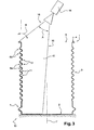
figure 3 shows the can according tofigure 1 , associated with a sprayer nozzle suitably arranged to partially lacquer its inner surface. - The
can 1 according to the invention, as shownfigure 1 , is composed of abottom wall 2, for example circular, from the periphery of which extends alateral wall 3, for example of a cylindrical shape.
The upper border 4 of saidlateral wall 3 defines anupper opening 5 thought which the foodstuff (not represented) is usually introduced into the can. This upper border 4 is also intended to receive a closing mean (not represented). - The
bottom wall 2 and thelateral wall 3 can be made in one piece. These twoelements - As shown
figures 1 and 2 , thelateral wall 3 has a plurality ofbeads 6, 7 which are here arranged on the main part of its height. - These
beads 6, 7 are here of an annular type (extending on the whole circumference of the lateral wall 3); in an alternative embodiment, they can also be of discontinuous or punctual type. - These
beads 6, 7 can be obtained by a usual beading operation. - The most of said beads 6 are identical and of a general half-circular shape. They extend alternatively in a convex and a concave manner, i.e. respectively towards inside (named 6a) and outside (named 6b) compare to the general surface of the
lateral wall 3.
This type of beads 6 is usually used to increase the lateral resistance of the can. - The
lateral wall 3 comprises also alower terminal bead 7, which has for example a V type concave shape which lay laterally. - These
beads 6, 7 have each - a first part 6', 7', oriented towards thebottom element 2 of said can 1, and - a second part 6", 7", oriented towards theupper opening 5 of said can 1.
More precisely, thefirst part 6b', 7' andsecond part 6b", 7" of eachconcave bead convex beads 6a, of which thefirst part 6a' andsecond part 6a" correspond respectively to their lower and upper parts. - The
can 1 is advantageously made of a steel matrix of which theinner surface 9, and at least the inner surface of itslateral wall 3, has a coating of tin and/or tin alloy. - This
inner tin surface 9 of the lateral beadedwall 3 is only partially coated with aprotective lacquer 10. Thebottom wall 2 is lacquered, but it can also be lacquerless or partially lacquerless.
The aim of this tin surface partially lacquered, as previously mentioned, is to be at least in part in contact with the conditioned foodstuff, in order to deliver a certain amount of tin into said foodstuff. - The type of lacquer used, and its thickness, can be chosen by one skill in the art, in particular function of the foodstuff packed.
- According to the invention, the partial lacquer of the height of the
lateral wall 3, and as a result at its exposedtin surface 9, is arranged to form an alternation of exposedtin zones 11 and lacqueredtin zones 12. - These exposed
zones 11 andlacquered zones 12 are each in band shape (here annular), extending into a general plan which is perpendicular to the longitudinal axis 1' of thecan 1. - This particular distribution of the exposed
tin zones 11 has for result to limit their aesthetic impact (darkened due to oxidation by foodstuff), but also to provide a delivery of tin on the whole height of the packed foodstuff (to allow a distribution nearly homogenous of the tin). - Moreover the exposed
tin zones 11 are here arranged and positioned in order to reduce even more their aesthetic impact, by taking advantage of the presence of thebeads 6, 7 above described. - To this aim, as shown
figures 1 and 2 , the exposedtin zones 11 are arranged at least on a part of theupper part 6b' of theconcave beads 6b (oriented towards thebottom wall 2 of the can); these exposedtin zones 11 can also extend partially on thelower part 6b" of saidconcave beads 6b (oriented towards theupper opening 5 of the can).
In other words, at least a part ofsaid tin zones 11 extends nearly in the "shadow" of the convex bead overlying 6a (viewed from the upper opening 5). These exposedtin zones 11 are arranged as more as possible on the bead sides which are not visually accessible, or hardly visually accessible, from theupper opening 5. - The said
convex beads 6a are here partially lacquerless on theirlower part 6a'. In an alternative embodiment, these convexbeads 6a can be fully lacquered. - Moreover, concerning the
terminal bead 7, the exposedtin zone 11 is arranged at its upper part 7'; itslower part 7" corresponds to a lacqueredzone 12. - In particular, the exposed tin zone represents advantageously between 5 % and 50 % of each
concave beads - To be complete, the non-beaded part of the
lateral wall 3 is here fully lacquered. In an alternative embodiment, this non-beaded part of thelateral wall 3 could also present exposed tin zones. - Such a particular pattern of lacquer coating is obtainable for example by mean of a device as described here-under according to
figure 3 . - This particular device, only partially shown
figure 3 , comprises a coating unit equipped with asupport element 13, receiving thecan 1 as described above, and asprayer nozzle 14 suitable to apply theprotective lacquer 10 on the inner surface of can. - As shown
figure 3 , the spray is advantageously arranged in front of theupper opening 5 of the can, outside of the volume defined by the lateral wall 3 (above the upper border 4). - This
nozzle 14 is arranged to generate aspray jet 15 which here hits at least thelateral wall 3, and here also a part of thebottom wall 2. - The said
spray jet 15 is here in shape of a thin film which extends in a general vertical plan. In alternative modes, thisspray jet 15 could also be in the general shape of a cone or a crown.
Thisspray jet 15 is defined particularly by twoouter edges 16 which delimit the vertical spraying angle A of saidnozzle 14. - The position of the
nozzle 14 relative to the longitudinal axis 1' of the can, and the angle B which is formed between the outer edge(s) 16 of the sprayingjet 14 and thelateral wall 3, are arranged to control the amount of exposed tin zones generated on thebeads 6, 7. - As shown
figure 3 , thenozzle 14 is arranged on the longitudinal axis 1' of thecan 1, or nearly on this longitudinal axis.
Moreover, theouter edge 16 of the sprayingjet 15 forms an angle B inferior to 90° with saidlateral wall 3. - In practice, during the coating step, the
sprayer nozzle 14 applies thelacquer 10 towards theinner surface 9 of thelateral wall 3. - In the same time, the
can 1 is operated in rotation around its longitudinal axis 1', thesprayer nozzle 14 remaining fixed. This rotation of thecan 1 allows the lacquering of the whole circumference of itslateral wall 3.
In an alternative embodiment, it is thenozzle 14 which is operated in rotation. - Also during this coating step, the
sprayer nozzle 14 could be moved in translation into the interior volume defined by thelateral wall 3. - In another embodiment, the exposed tin zones are obtained by mean of a preset timing cycle of spray opening and closure according to the relative position between the can and the nozzle.
- As above-mentioned, the particular spraying orientation allows the lacquering of only the lateral wall surface which is in regard of the nozzle, i.e. mainly the surface which is hit by the spraying jet. This hit surface corresponds to the lacquered
zones 12 of the can previously described according tofigures 1 and 2 .
The zones of the lateral wall surface which are not hit by the spraying jet correspond then to the exposedtin zones 11. - The can obtained is then the same as the one described above according to
figures 1 and 2 . - In an alternative embodiment, the coating means of the device could also consist for example in a suitable brush, brush pat, sponge and or a roller.
These coating means are suitably operated to obtain the particular lacquered pattern above-discribed. - In general words, the can according to the invention presents an inner surface which is partially lacquered. The exposed tin zones are arranged on the hiding part of the beads, which even more limit their visual impact. Moreover, the exposed tin zones are distributed on the height of the lateral wall which permits a better distribution of tin into the foodstuff.
Claims (13)
- Can for conditioning foodstuff, comprising a body of can composed of a bottom element (2) which is prolonged by a lateral wall (3) of which upper border (4) defines an upper opening (5) intended to receive a closure mean, the interior surface (9) of said body being at least in part made of tin, said tin surface (9) being partially covered with a coating of protective lacquer (10) to prevent the contact between said tin surface (9) and said foodstuff, the lacquerless tin surface, said "exposed", being intended to come into contact with the foodstuff in order to set free said tin, characterised in that
said exposed tin surface is constituted of a plurality of "exposed" tin zones (11), which are separated, ones from the others, by lacquered zones (12), said exposed tin zones (11) being distributed on the height of said lateral wall (3), in particular to limit the aesthetic impact due to chemical action of said foodstuff on said exposed tin zones (11). - Can for conditioning foodstuff according to claim 1, wherein said exposed tin zones (11) are distributed homogeneously, or quasi-homogeneously, on said tin surface (9).
- Can for conditioning foodstuff according to claims 1 or 2, wherein the tin surface (9) comprises an alternation of lacquered zones (12) and exposed tin zones (11), said zones (11, 12) each having a general shape of band, and said zones (11, 12) being distributed on at least a part of the height of the lateral wall (3) and being arranged according plans perpendicular to the longitudinal axis (1') of the body of can.
- Can for conditioning foodstuff according to claim 3, of which the lateral wall (3) comprises at least a bead (6, 7) of which the interior surface (9) is at least in part made of tin, wherein said bead (6, 7) comprises an exposed tin zone (11) which is arranged on at least a part of its surface.
- Can for conditioning foodstuff according to claim 4, of which at least some of the beads (6, 7) have hidden part (6', 7'), oriented towards the bottom element (2) of said can, wherein the exposed tin zone (11) of said beads (6, 7) is arranged mainly at their said hidden part (6', 7'), the rest of the surface of said beads (6, 7) corresponding to lacquered zone (12).
- Can for conditioning foodstuff according to claims 4 or 5, wherein at least some of the beads (6) have a curved shape, extending alternatively in a convex and a concave manners, and wherein the hidden part (6b') of said concave beads (6b), oriented towards the bottom element (2) of said can (1), comprising an exposed tin zone (11).
- Can for conditioning foodstuff according to claims 4 to 6, wherein the beads (6, 7) extend in a annular shape on the circumference of the lateral wall (3), and wherein the associated exposed tin zones (11) are of annular band shape.
- Can for conditioning foodstuff according to claims 4 to 7, wherein the exposed tin zone (11), arranged on the bead (6, 7), is between 5 % to 50 % of the total surface of said bead.
- Process to manufacture a can for conditioning foodstuff according to claims 1 to 8, said process comprising at least a step of coating the interior surface (9) of the lateral wall (3) with a protective lacquer (10) by using a coating means (14),
wherein said coating step consists in coating the interior surface (9) of said lateral wall (3) with the protective lacquer (10) such as to form a plurality of "exposed" tin zones (11), which are separated, ones from the others, by lacquered zones (12), said exposed tin zones (11) being distributed on the height of said lateral wall (3). - Process to manufacture a can for conditioning foodstuff according to claim 9, wherein, during the coating step, the can (1) and/or the coating means are operated in rotation one relative to the other, around the longitudinal axis (1') of said can (1).
- Process to manufacture a can for conditioning foodstuff according to claims 9 or 10, in which said can (1) has a lateral wall (3) arranged with at least one bead (6, 7) and in which the coating means comprise at least one sprayer nozzle, wherein, during the coating step, the sprayer nozzle (14) is positioned in front of the upper opening (5) of the can (1), outside the interior volume defined by the lateral wall (3), and sprays the protective lacquer (10) towards said lateral wall (3) of the can (1).
- Process to manufacture a can for conditioning foodstuff according to claim 11, wherein the can (1) and/or the spraying nozzle (14) are operated in longitudinal translation one relative to the other, the spray of protective lacquer (15) being arranged so that its outer edge (16) forms an angle B with the lateral wall (3) which is inferior to 90°.
- Process to manufacture a can for conditioning foodstuff according to claims 9 to 12, in which the coating means comprise at least one sprayer nozzle, wherein the exposed tin zones (11) are obtained by mean of a preset timing cycle of spray opening and closure according to the relative position between the can (1) and the nozzle (14).
Priority Applications (22)
| Application Number | Priority Date | Filing Date | Title |
|---|---|---|---|
| AT08300053T ATE530454T1 (en) | 2008-01-25 | 2008-01-25 | CAN WITH PARTIAL INTERIOR PAINTING AND METHOD FOR PRODUCING THE SAME |
| EP08300053A EP2082968B1 (en) | 2008-01-25 | 2008-01-25 | Can with partial interior lacquering and method for manufacturing the same |
| PT08300053T PT2082968E (en) | 2008-01-25 | 2008-01-25 | Can with partial interior lacquering and method for manufacturing the same |
| ES08300053T ES2374328T3 (en) | 2008-01-25 | 2008-01-25 | CAN WITH PARTIAL INTERIOR LACQUERED AND PROCEDURE FOR MANUFACTURING. |
| PL08300053T PL2082968T3 (en) | 2008-01-25 | 2008-01-25 | Can with partial interior lacquering and method for manufacturing the same |
| UAA201010278A UA102089C2 (en) | 2008-01-25 | 2009-01-23 | Can with partially lacquered inner surface and method of its manufacture |
| JP2010543504A JP5436450B2 (en) | 2008-01-25 | 2009-01-23 | Can partially coated with resin inside, method and apparatus for manufacturing the same |
| KR1020107016617A KR101531255B1 (en) | 2008-01-25 | 2009-01-23 | Can with partial interior lacquering, method and device for manufacturing the same |
| NZ586905A NZ586905A (en) | 2008-01-25 | 2009-01-23 | Can with partial interior lacquering, method and device for manufacturing the same |
| CN2009801031108A CN101925519B (en) | 2008-01-25 | 2009-01-23 | Can with partial interior lacquering, method and device for manufacturing the same |
| CA2713130A CA2713130C (en) | 2008-01-25 | 2009-01-23 | Can with partial interior lacquering, method and device for manufacturing the same |
| AU2009207625A AU2009207625B2 (en) | 2008-01-25 | 2009-01-23 | Can with partial interior lacquering, method and device for manufacturing the same |
| RU2010135515/12A RU2485030C2 (en) | 2008-01-25 | 2009-01-23 | Tin with partially varnished inner surface, method and device for its manufacture |
| GEAP200911926A GEP20125562B (en) | 2008-01-25 | 2009-01-23 | Can with partial interior lacquering, method and device for manufacturing the same |
| US12/863,888 US8967409B2 (en) | 2008-01-25 | 2009-01-23 | Can with partial interior lacquering, method and device for manufacturing the same |
| TW098103099A TW200948673A (en) | 2008-01-25 | 2009-01-23 | Can in particular for conditioning foodstuff, with partial interior lacquering |
| BRPI0906783-3A BRPI0906783A2 (en) | 2008-01-25 | 2009-01-23 | Can for packaging food, process for making a can, and device for making a can and / or for implementing a process |
| PCT/EP2009/050769 WO2009092786A1 (en) | 2008-01-25 | 2009-01-23 | Can with partial interior lacquering, method and device for manufacturing the same |
| ARP090100230A AR070256A1 (en) | 2008-01-25 | 2009-01-26 | CAN, IN PARTICULAR TO PACK FOOD PRODUCTS, WITH PARTIAL INTERIOR LACQUERED |
| CL2009000162A CL2009000162A1 (en) | 2008-01-25 | 2009-01-26 | Can for packaging food products, has a body with a bottom element, a side wall whose upper edge defines an upper opening with closing means, where the inner surface of the body has a protective lacquer at least in part of it; manufacturing procedure; and manufacturing device. |
| MA33021A MA32020B1 (en) | 2008-01-25 | 2010-07-15 | Box before partial internal lacquering, method and apparatus for its manufacture |
| ZA2010/05184A ZA201005184B (en) | 2008-01-25 | 2010-07-20 | Can with partial interior lacquering,method and device for manufacturing the same |
Applications Claiming Priority (1)
| Application Number | Priority Date | Filing Date | Title |
|---|---|---|---|
| EP08300053A EP2082968B1 (en) | 2008-01-25 | 2008-01-25 | Can with partial interior lacquering and method for manufacturing the same |
Publications (2)
| Publication Number | Publication Date |
|---|---|
| EP2082968A1 EP2082968A1 (en) | 2009-07-29 |
| EP2082968B1 true EP2082968B1 (en) | 2011-10-26 |
Family
ID=39468827
Family Applications (1)
| Application Number | Title | Priority Date | Filing Date |
|---|---|---|---|
| EP08300053A Not-in-force EP2082968B1 (en) | 2008-01-25 | 2008-01-25 | Can with partial interior lacquering and method for manufacturing the same |
Country Status (22)
| Country | Link |
|---|---|
| US (1) | US8967409B2 (en) |
| EP (1) | EP2082968B1 (en) |
| JP (1) | JP5436450B2 (en) |
| KR (1) | KR101531255B1 (en) |
| CN (1) | CN101925519B (en) |
| AR (1) | AR070256A1 (en) |
| AT (1) | ATE530454T1 (en) |
| AU (1) | AU2009207625B2 (en) |
| BR (1) | BRPI0906783A2 (en) |
| CA (1) | CA2713130C (en) |
| CL (1) | CL2009000162A1 (en) |
| ES (1) | ES2374328T3 (en) |
| GE (1) | GEP20125562B (en) |
| MA (1) | MA32020B1 (en) |
| NZ (1) | NZ586905A (en) |
| PL (1) | PL2082968T3 (en) |
| PT (1) | PT2082968E (en) |
| RU (1) | RU2485030C2 (en) |
| TW (1) | TW200948673A (en) |
| UA (1) | UA102089C2 (en) |
| WO (1) | WO2009092786A1 (en) |
| ZA (1) | ZA201005184B (en) |
Families Citing this family (6)
| Publication number | Priority date | Publication date | Assignee | Title |
|---|---|---|---|---|
| FR2954291B1 (en) * | 2009-12-17 | 2012-03-09 | Impress Group Bv | CONTAINER IN THE FORM OF CANISTER BOX WITH INTERNAL PROTECTION LAYER |
| US8127588B1 (en) | 2011-03-23 | 2012-03-06 | Halpin Harold W | Apparatus and methods for forming a finger-engaging portion in a stay-on-tab of a lid of a container |
| CN102580646A (en) * | 2012-02-28 | 2012-07-18 | 张家港市驰耐特防腐科技有限公司 | Corrosion resistant reaction kettle |
| GB201211077D0 (en) * | 2012-06-22 | 2012-08-01 | Crown Packaging Technology Inc | Two-piece can |
| US10065232B2 (en) | 2013-03-15 | 2018-09-04 | Station 4 Llc | Devices and methods for bending a tab on a container |
| JP6694971B2 (en) * | 2016-01-15 | 2020-05-20 | サーブ・ボフォース・ダイナミクス・スウィツァランド・リミテッド | Crushing sleeve for ammunition body |
Family Cites Families (17)
| Publication number | Priority date | Publication date | Assignee | Title |
|---|---|---|---|---|
| US1811160A (en) * | 1928-06-05 | 1931-06-23 | Continental Can Co | Container for food products |
| US3888224A (en) * | 1969-05-30 | 1975-06-10 | Bosch Gmbh Robert | Liquid food preservation |
| US3784048A (en) * | 1970-09-09 | 1974-01-08 | Dorn Co V | Containers for corrosive food products |
| US3687334A (en) * | 1970-09-23 | 1972-08-29 | Del Monte Corp | Metal container with removable closure |
| JPS5344614Y2 (en) * | 1972-02-18 | 1978-10-26 | ||
| US4054227A (en) * | 1973-08-09 | 1977-10-18 | National Steel Corporation | Selective coating characteristic tinplated steel cans |
| US3947617A (en) * | 1974-07-08 | 1976-03-30 | Eppco | Coated container |
| JPS5237170A (en) * | 1975-09-16 | 1977-03-22 | Yoshizaki Kozo | Sealed container with superior prevention effect against oxidation |
| US4459793A (en) * | 1980-04-28 | 1984-07-17 | National Can Corporation | Composite container construction |
| JPS60112672U (en) * | 1984-01-07 | 1985-07-30 | 株式会社 土屋製作所 | Fuel filter cylindrical container |
| JPS61115862A (en) * | 1984-11-06 | 1986-06-03 | サントリー株式会社 | Vessel having deoxidizing function |
| JPS61161182A (en) * | 1984-12-29 | 1986-07-21 | Nordson Kk | Coating method of seam part on can inside |
| GB9027954D0 (en) * | 1990-12-22 | 1991-02-13 | Cmb Foodcan Plc | Containers |
| GB9216247D0 (en) * | 1992-07-30 | 1992-09-09 | Cmb Foodcan Plc | Souffle:can ends |
| JPH0896054A (en) * | 1994-09-29 | 1996-04-12 | Toshiba Corp | Transaction information processing device |
| IL150397A0 (en) * | 2000-01-14 | 2002-12-01 | Astrazeneca Ab | A method for applying a polymer coating to the internal surface of a container |
| EP1201331A1 (en) * | 2000-09-27 | 2002-05-02 | Novocan AG | Method for manufacturing a metal can provided with a decoration layer and Device for implementing the method |
-
2008
- 2008-01-25 PT PT08300053T patent/PT2082968E/en unknown
- 2008-01-25 ES ES08300053T patent/ES2374328T3/en active Active
- 2008-01-25 AT AT08300053T patent/ATE530454T1/en active
- 2008-01-25 EP EP08300053A patent/EP2082968B1/en not_active Not-in-force
- 2008-01-25 PL PL08300053T patent/PL2082968T3/en unknown
-
2009
- 2009-01-23 RU RU2010135515/12A patent/RU2485030C2/en not_active IP Right Cessation
- 2009-01-23 BR BRPI0906783-3A patent/BRPI0906783A2/en not_active Application Discontinuation
- 2009-01-23 CN CN2009801031108A patent/CN101925519B/en not_active Expired - Fee Related
- 2009-01-23 GE GEAP200911926A patent/GEP20125562B/en unknown
- 2009-01-23 TW TW098103099A patent/TW200948673A/en unknown
- 2009-01-23 JP JP2010543504A patent/JP5436450B2/en not_active Expired - Fee Related
- 2009-01-23 WO PCT/EP2009/050769 patent/WO2009092786A1/en not_active Ceased
- 2009-01-23 US US12/863,888 patent/US8967409B2/en not_active Expired - Fee Related
- 2009-01-23 NZ NZ586905A patent/NZ586905A/en not_active IP Right Cessation
- 2009-01-23 AU AU2009207625A patent/AU2009207625B2/en not_active Ceased
- 2009-01-23 CA CA2713130A patent/CA2713130C/en not_active Expired - Fee Related
- 2009-01-23 UA UAA201010278A patent/UA102089C2/en unknown
- 2009-01-23 KR KR1020107016617A patent/KR101531255B1/en not_active Expired - Fee Related
- 2009-01-26 CL CL2009000162A patent/CL2009000162A1/en unknown
- 2009-01-26 AR ARP090100230A patent/AR070256A1/en unknown
-
2010
- 2010-07-15 MA MA33021A patent/MA32020B1/en unknown
- 2010-07-20 ZA ZA2010/05184A patent/ZA201005184B/en unknown
Also Published As
| Publication number | Publication date |
|---|---|
| AU2009207625A1 (en) | 2009-07-30 |
| BRPI0906783A2 (en) | 2015-07-14 |
| CA2713130A1 (en) | 2009-07-30 |
| CN101925519A (en) | 2010-12-22 |
| AU2009207625B2 (en) | 2013-03-07 |
| AR070256A1 (en) | 2010-03-25 |
| US8967409B2 (en) | 2015-03-03 |
| KR101531255B1 (en) | 2015-06-24 |
| MA32020B1 (en) | 2011-01-03 |
| CA2713130C (en) | 2016-11-08 |
| GEP20125562B (en) | 2012-06-25 |
| TW200948673A (en) | 2009-12-01 |
| PL2082968T3 (en) | 2012-03-30 |
| CL2009000162A1 (en) | 2012-05-11 |
| ATE530454T1 (en) | 2011-11-15 |
| ZA201005184B (en) | 2011-05-25 |
| UA102089C2 (en) | 2013-06-10 |
| KR20100131421A (en) | 2010-12-15 |
| RU2485030C2 (en) | 2013-06-20 |
| EP2082968A1 (en) | 2009-07-29 |
| JP5436450B2 (en) | 2014-03-05 |
| ES2374328T3 (en) | 2012-02-15 |
| NZ586905A (en) | 2011-12-22 |
| US20100307953A1 (en) | 2010-12-09 |
| RU2010135515A (en) | 2012-02-27 |
| WO2009092786A1 (en) | 2009-07-30 |
| PT2082968E (en) | 2012-01-17 |
| CN101925519B (en) | 2011-12-28 |
| JP2011509895A (en) | 2011-03-31 |
Similar Documents
| Publication | Publication Date | Title |
|---|---|---|
| CA2713130C (en) | Can with partial interior lacquering, method and device for manufacturing the same | |
| EP2864213B1 (en) | Partially coated two-piece tinplate can | |
| US8978915B2 (en) | Can end with strengthening bead configuration | |
| US8978922B2 (en) | Strengthened food container and method | |
| US20130026169A1 (en) | Can end with strengthening bead configuration | |
| US20020030126A1 (en) | Spray nozzle with improved asymmetrical fluid discharge distribution | |
| US4054227A (en) | Selective coating characteristic tinplated steel cans | |
| US10106306B2 (en) | Can end for pressurized metal food can with shielded vent score | |
| US2864529A (en) | Overcapped container top structure | |
| US9511902B2 (en) | Can-shaped container having a protective inner layer | |
| JP2003095231A (en) | Method for manufacturing printed film-laminated cans | |
| JP2021169078A (en) | Container manufacturing method |
Legal Events
| Date | Code | Title | Description |
|---|---|---|---|
| PUAI | Public reference made under article 153(3) epc to a published international application that has entered the european phase |
Free format text: ORIGINAL CODE: 0009012 |
|
| AK | Designated contracting states |
Kind code of ref document: A1 Designated state(s): AT BE BG CH CY CZ DE DK EE ES FI FR GB GR HR HU IE IS IT LI LT LU LV MC MT NL NO PL PT RO SE SI SK TR |
|
| AX | Request for extension of the european patent |
Extension state: AL BA MK RS |
|
| 17P | Request for examination filed |
Effective date: 20100127 |
|
| 17Q | First examination report despatched |
Effective date: 20100224 |
|
| AKX | Designation fees paid |
Designated state(s): AT BE BG CH CY CZ DE DK EE ES FI FR GB GR HR HU IE IS IT LI LT LU LV MC MT NL NO PL PT RO SE SI SK TR |
|
| RTI1 | Title (correction) |
Free format text: CAN WITH PARTIAL INTERIOR LACQUERING AND METHOD FOR MANUFACTURING THE SAME |
|
| GRAP | Despatch of communication of intention to grant a patent |
Free format text: ORIGINAL CODE: EPIDOSNIGR1 |
|
| GRAS | Grant fee paid |
Free format text: ORIGINAL CODE: EPIDOSNIGR3 |
|
| GRAA | (expected) grant |
Free format text: ORIGINAL CODE: 0009210 |
|
| RAP1 | Party data changed (applicant data changed or rights of an application transferred) |
Owner name: ARDAGH MP GROUP NETHERLANDS B.V. |
|
| AK | Designated contracting states |
Kind code of ref document: B1 Designated state(s): AT BE BG CH CY CZ DE DK EE ES FI FR GB GR HR HU IE IS IT LI LT LU LV MC MT NL NO PL PT RO SE SI SK TR |
|
| REG | Reference to a national code |
Ref country code: GB Ref legal event code: FG4D |
|
| REG | Reference to a national code |
Ref country code: CH Ref legal event code: EP |
|
| REG | Reference to a national code |
Ref country code: IE Ref legal event code: FG4D |
|
| REG | Reference to a national code |
Ref country code: RO Ref legal event code: EPE |
|
| REG | Reference to a national code |
Ref country code: DE Ref legal event code: R096 Ref document number: 602008010813 Country of ref document: DE Effective date: 20111222 |
|
| REG | Reference to a national code |
Ref country code: NL Ref legal event code: T3 |
|
| REG | Reference to a national code |
Ref country code: PT Ref legal event code: SC4A Free format text: AVAILABILITY OF NATIONAL TRANSLATION Effective date: 20120109 |
|
| REG | Reference to a national code |
Ref country code: SE Ref legal event code: TRGR |
|
| REG | Reference to a national code |
Ref country code: ES Ref legal event code: FG2A Ref document number: 2374328 Country of ref document: ES Kind code of ref document: T3 Effective date: 20120215 |
|
| LTIE | Lt: invalidation of european patent or patent extension |
Effective date: 20111026 |
|
| REG | Reference to a national code |
Ref country code: GR Ref legal event code: EP Ref document number: 20110403097 Country of ref document: GR Effective date: 20120206 |
|
| REG | Reference to a national code |
Ref country code: PL Ref legal event code: T3 |
|
| PG25 | Lapsed in a contracting state [announced via postgrant information from national office to epo] |
Ref country code: LT Free format text: LAPSE BECAUSE OF FAILURE TO SUBMIT A TRANSLATION OF THE DESCRIPTION OR TO PAY THE FEE WITHIN THE PRESCRIBED TIME-LIMIT Effective date: 20111026 Ref country code: NO Free format text: LAPSE BECAUSE OF FAILURE TO SUBMIT A TRANSLATION OF THE DESCRIPTION OR TO PAY THE FEE WITHIN THE PRESCRIBED TIME-LIMIT Effective date: 20120126 Ref country code: IS Free format text: LAPSE BECAUSE OF FAILURE TO SUBMIT A TRANSLATION OF THE DESCRIPTION OR TO PAY THE FEE WITHIN THE PRESCRIBED TIME-LIMIT Effective date: 20120226 |
|
| PG25 | Lapsed in a contracting state [announced via postgrant information from national office to epo] |
Ref country code: LV Free format text: LAPSE BECAUSE OF FAILURE TO SUBMIT A TRANSLATION OF THE DESCRIPTION OR TO PAY THE FEE WITHIN THE PRESCRIBED TIME-LIMIT Effective date: 20111026 Ref country code: SI Free format text: LAPSE BECAUSE OF FAILURE TO SUBMIT A TRANSLATION OF THE DESCRIPTION OR TO PAY THE FEE WITHIN THE PRESCRIBED TIME-LIMIT Effective date: 20111026 Ref country code: HR Free format text: LAPSE BECAUSE OF FAILURE TO SUBMIT A TRANSLATION OF THE DESCRIPTION OR TO PAY THE FEE WITHIN THE PRESCRIBED TIME-LIMIT Effective date: 20111026 |
|
| PG25 | Lapsed in a contracting state [announced via postgrant information from national office to epo] |
Ref country code: CY Free format text: LAPSE BECAUSE OF FAILURE TO SUBMIT A TRANSLATION OF THE DESCRIPTION OR TO PAY THE FEE WITHIN THE PRESCRIBED TIME-LIMIT Effective date: 20111026 |
|
| PG25 | Lapsed in a contracting state [announced via postgrant information from national office to epo] |
Ref country code: EE Free format text: LAPSE BECAUSE OF FAILURE TO SUBMIT A TRANSLATION OF THE DESCRIPTION OR TO PAY THE FEE WITHIN THE PRESCRIBED TIME-LIMIT Effective date: 20111026 Ref country code: DK Free format text: LAPSE BECAUSE OF FAILURE TO SUBMIT A TRANSLATION OF THE DESCRIPTION OR TO PAY THE FEE WITHIN THE PRESCRIBED TIME-LIMIT Effective date: 20111026 Ref country code: SK Free format text: LAPSE BECAUSE OF FAILURE TO SUBMIT A TRANSLATION OF THE DESCRIPTION OR TO PAY THE FEE WITHIN THE PRESCRIBED TIME-LIMIT Effective date: 20111026 |
|
| PG25 | Lapsed in a contracting state [announced via postgrant information from national office to epo] |
Ref country code: MC Free format text: LAPSE BECAUSE OF NON-PAYMENT OF DUE FEES Effective date: 20120131 |
|
| PLBE | No opposition filed within time limit |
Free format text: ORIGINAL CODE: 0009261 |
|
| REG | Reference to a national code |
Ref country code: CH Ref legal event code: PL |
|
| STAA | Information on the status of an ep patent application or granted ep patent |
Free format text: STATUS: NO OPPOSITION FILED WITHIN TIME LIMIT |
|
| 26N | No opposition filed |
Effective date: 20120727 |
|
| REG | Reference to a national code |
Ref country code: IE Ref legal event code: MM4A |
|
| PG25 | Lapsed in a contracting state [announced via postgrant information from national office to epo] |
Ref country code: CH Free format text: LAPSE BECAUSE OF NON-PAYMENT OF DUE FEES Effective date: 20120131 Ref country code: LI Free format text: LAPSE BECAUSE OF NON-PAYMENT OF DUE FEES Effective date: 20120131 |
|
| REG | Reference to a national code |
Ref country code: HU Ref legal event code: AG4A Ref document number: E014020 Country of ref document: HU |
|
| REG | Reference to a national code |
Ref country code: DE Ref legal event code: R097 Ref document number: 602008010813 Country of ref document: DE Effective date: 20120727 |
|
| PG25 | Lapsed in a contracting state [announced via postgrant information from national office to epo] |
Ref country code: IE Free format text: LAPSE BECAUSE OF NON-PAYMENT OF DUE FEES Effective date: 20120125 |
|
| PGFP | Annual fee paid to national office [announced via postgrant information from national office to epo] |
Ref country code: SE Payment date: 20121211 Year of fee payment: 6 |
|
| PGFP | Annual fee paid to national office [announced via postgrant information from national office to epo] |
Ref country code: BG Payment date: 20130111 Year of fee payment: 6 |
|
| PG25 | Lapsed in a contracting state [announced via postgrant information from national office to epo] |
Ref country code: FI Free format text: LAPSE BECAUSE OF FAILURE TO SUBMIT A TRANSLATION OF THE DESCRIPTION OR TO PAY THE FEE WITHIN THE PRESCRIBED TIME-LIMIT Effective date: 20111026 |
|
| PGFP | Annual fee paid to national office [announced via postgrant information from national office to epo] |
Ref country code: PT Payment date: 20130117 Year of fee payment: 6 Ref country code: AT Payment date: 20121210 Year of fee payment: 6 |
|
| PG25 | Lapsed in a contracting state [announced via postgrant information from national office to epo] |
Ref country code: MT Free format text: LAPSE BECAUSE OF FAILURE TO SUBMIT A TRANSLATION OF THE DESCRIPTION OR TO PAY THE FEE WITHIN THE PRESCRIBED TIME-LIMIT Effective date: 20111026 |
|
| PGFP | Annual fee paid to national office [announced via postgrant information from national office to epo] |
Ref country code: RO Payment date: 20140120 Year of fee payment: 7 Ref country code: BE Payment date: 20140107 Year of fee payment: 7 |
|
| PG25 | Lapsed in a contracting state [announced via postgrant information from national office to epo] |
Ref country code: LU Free format text: LAPSE BECAUSE OF NON-PAYMENT OF DUE FEES Effective date: 20120125 |
|
| PGFP | Annual fee paid to national office [announced via postgrant information from national office to epo] |
Ref country code: GR Payment date: 20140121 Year of fee payment: 7 Ref country code: HU Payment date: 20140121 Year of fee payment: 7 Ref country code: IT Payment date: 20140123 Year of fee payment: 7 |
|
| REG | Reference to a national code |
Ref country code: PT Ref legal event code: MM4A Free format text: LAPSE DUE TO NON-PAYMENT OF FEES Effective date: 20140725 |
|
| REG | Reference to a national code |
Ref country code: AT Ref legal event code: MM01 Ref document number: 530454 Country of ref document: AT Kind code of ref document: T Effective date: 20140125 |
|
| REG | Reference to a national code |
Ref country code: SE Ref legal event code: EUG |
|
| PG25 | Lapsed in a contracting state [announced via postgrant information from national office to epo] |
Ref country code: BG Free format text: LAPSE BECAUSE OF NON-PAYMENT OF DUE FEES Effective date: 20140930 |
|
| PG25 | Lapsed in a contracting state [announced via postgrant information from national office to epo] |
Ref country code: SE Free format text: LAPSE BECAUSE OF NON-PAYMENT OF DUE FEES Effective date: 20140126 Ref country code: AT Free format text: LAPSE BECAUSE OF NON-PAYMENT OF DUE FEES Effective date: 20140125 |
|
| PG25 | Lapsed in a contracting state [announced via postgrant information from national office to epo] |
Ref country code: PT Free format text: LAPSE BECAUSE OF NON-PAYMENT OF DUE FEES Effective date: 20140725 |
|
| PGFP | Annual fee paid to national office [announced via postgrant information from national office to epo] |
Ref country code: PL Payment date: 20141209 Year of fee payment: 8 |
|
| PG25 | Lapsed in a contracting state [announced via postgrant information from national office to epo] |
Ref country code: BE Free format text: LAPSE BECAUSE OF NON-PAYMENT OF DUE FEES Effective date: 20150131 |
|
| REG | Reference to a national code |
Ref country code: GR Ref legal event code: ML Ref document number: 20110403097 Country of ref document: GR Effective date: 20150805 |
|
| PG25 | Lapsed in a contracting state [announced via postgrant information from national office to epo] |
Ref country code: RO Free format text: LAPSE BECAUSE OF NON-PAYMENT OF DUE FEES Effective date: 20150125 |
|
| PG25 | Lapsed in a contracting state [announced via postgrant information from national office to epo] |
Ref country code: GR Free format text: LAPSE BECAUSE OF NON-PAYMENT OF DUE FEES Effective date: 20150805 Ref country code: HU Free format text: LAPSE BECAUSE OF NON-PAYMENT OF DUE FEES Effective date: 20150126 |
|
| REG | Reference to a national code |
Ref country code: FR Ref legal event code: PLFP Year of fee payment: 9 |
|
| PG25 | Lapsed in a contracting state [announced via postgrant information from national office to epo] |
Ref country code: IT Free format text: LAPSE BECAUSE OF NON-PAYMENT OF DUE FEES Effective date: 20150125 |
|
| REG | Reference to a national code |
Ref country code: FR Ref legal event code: PLFP Year of fee payment: 10 |
|
| PG25 | Lapsed in a contracting state [announced via postgrant information from national office to epo] |
Ref country code: PL Free format text: LAPSE BECAUSE OF NON-PAYMENT OF DUE FEES Effective date: 20160125 |
|
| PG25 | Lapsed in a contracting state [announced via postgrant information from national office to epo] |
Ref country code: TR Free format text: LAPSE BECAUSE OF NON-PAYMENT OF DUE FEES Effective date: 20140125 |
|
| REG | Reference to a national code |
Ref country code: FR Ref legal event code: PLFP Year of fee payment: 11 |
|
| PGFP | Annual fee paid to national office [announced via postgrant information from national office to epo] |
Ref country code: FR Payment date: 20171201 Year of fee payment: 11 |
|
| PGFP | Annual fee paid to national office [announced via postgrant information from national office to epo] |
Ref country code: GB Payment date: 20171201 Year of fee payment: 11 |
|
| PGFP | Annual fee paid to national office [announced via postgrant information from national office to epo] |
Ref country code: NL Payment date: 20180119 Year of fee payment: 11 |
|
| PGFP | Annual fee paid to national office [announced via postgrant information from national office to epo] |
Ref country code: CZ Payment date: 20180122 Year of fee payment: 11 Ref country code: ES Payment date: 20180209 Year of fee payment: 11 Ref country code: DE Payment date: 20171206 Year of fee payment: 11 |
|
| REG | Reference to a national code |
Ref country code: DE Ref legal event code: R119 Ref document number: 602008010813 Country of ref document: DE |
|
| REG | Reference to a national code |
Ref country code: NL Ref legal event code: MM Effective date: 20190201 |
|
| GBPC | Gb: european patent ceased through non-payment of renewal fee |
Effective date: 20190125 |
|
| PG25 | Lapsed in a contracting state [announced via postgrant information from national office to epo] |
Ref country code: DE Free format text: LAPSE BECAUSE OF NON-PAYMENT OF DUE FEES Effective date: 20190801 Ref country code: FR Free format text: LAPSE BECAUSE OF NON-PAYMENT OF DUE FEES Effective date: 20190131 Ref country code: NL Free format text: LAPSE BECAUSE OF NON-PAYMENT OF DUE FEES Effective date: 20190201 Ref country code: CZ Free format text: LAPSE BECAUSE OF NON-PAYMENT OF DUE FEES Effective date: 20190125 |
|
| PG25 | Lapsed in a contracting state [announced via postgrant information from national office to epo] |
Ref country code: GB Free format text: LAPSE BECAUSE OF NON-PAYMENT OF DUE FEES Effective date: 20190125 |
|
| REG | Reference to a national code |
Ref country code: ES Ref legal event code: FD2A Effective date: 20200310 |
|
| PG25 | Lapsed in a contracting state [announced via postgrant information from national office to epo] |
Ref country code: ES Free format text: LAPSE BECAUSE OF NON-PAYMENT OF DUE FEES Effective date: 20190126 |