EP2082851A1 - An industrial robot capable of supervising its environmental impact and a method thereof - Google Patents
An industrial robot capable of supervising its environmental impact and a method thereof Download PDFInfo
- Publication number
- EP2082851A1 EP2082851A1 EP08156349A EP08156349A EP2082851A1 EP 2082851 A1 EP2082851 A1 EP 2082851A1 EP 08156349 A EP08156349 A EP 08156349A EP 08156349 A EP08156349 A EP 08156349A EP 2082851 A1 EP2082851 A1 EP 2082851A1
- Authority
- EP
- European Patent Office
- Prior art keywords
- robot
- environmental impact
- power consumption
- increased
- service
- Prior art date
- Legal status (The legal status is an assumption and is not a legal conclusion. Google has not performed a legal analysis and makes no representation as to the accuracy of the status listed.)
- Withdrawn
Links
Images

Classifications
-
- G—PHYSICS
- G05—CONTROLLING; REGULATING
- G05B—CONTROL OR REGULATING SYSTEMS IN GENERAL; FUNCTIONAL ELEMENTS OF SUCH SYSTEMS; MONITORING OR TESTING ARRANGEMENTS FOR SUCH SYSTEMS OR ELEMENTS
- G05B19/00—Program-control systems
- G05B19/02—Program-control systems electric
- G05B19/18—Numerical control [NC], i.e. automatically operating machines, in particular machine tools, e.g. in a manufacturing environment, so as to execute positioning, movement or co-ordinated operations by means of program data in numerical form
- G05B19/406—Numerical control [NC], i.e. automatically operating machines, in particular machine tools, e.g. in a manufacturing environment, so as to execute positioning, movement or co-ordinated operations by means of program data in numerical form characterised by monitoring or safety
-
- B—PERFORMING OPERATIONS; TRANSPORTING
- B25—HAND TOOLS; PORTABLE POWER-DRIVEN TOOLS; MANIPULATORS
- B25J—MANIPULATORS; CHAMBERS PROVIDED WITH MANIPULATION DEVICES
- B25J9/00—Program-controlled manipulators
- B25J9/16—Program controls
- B25J9/1674—Program controls characterised by safety, monitoring, diagnostic
-
- G—PHYSICS
- G05—CONTROLLING; REGULATING
- G05B—CONTROL OR REGULATING SYSTEMS IN GENERAL; FUNCTIONAL ELEMENTS OF SUCH SYSTEMS; MONITORING OR TESTING ARRANGEMENTS FOR SUCH SYSTEMS OR ELEMENTS
- G05B2219/00—Program-control systems
- G05B2219/30—Nc systems
- G05B2219/32—Operator till task planning
- G05B2219/32021—Energy management, balance and limit power to tools
-
- G—PHYSICS
- G05—CONTROLLING; REGULATING
- G05B—CONTROL OR REGULATING SYSTEMS IN GENERAL; FUNCTIONAL ELEMENTS OF SUCH SYSTEMS; MONITORING OR TESTING ARRANGEMENTS FOR SUCH SYSTEMS OR ELEMENTS
- G05B2219/00—Program-control systems
- G05B2219/30—Nc systems
- G05B2219/37—Measurements
- G05B2219/37348—Power, wattmeter voltage times current
-
- G—PHYSICS
- G05—CONTROLLING; REGULATING
- G05B—CONTROL OR REGULATING SYSTEMS IN GENERAL; FUNCTIONAL ELEMENTS OF SUCH SYSTEMS; MONITORING OR TESTING ARRANGEMENTS FOR SUCH SYSTEMS OR ELEMENTS
- G05B2219/00—Program-control systems
- G05B2219/30—Nc systems
- G05B2219/39—Robotics, robotics to robotics hand
- G05B2219/39412—Diagnostic of robot, estimation of parameters
-
- G—PHYSICS
- G05—CONTROLLING; REGULATING
- G05B—CONTROL OR REGULATING SYSTEMS IN GENERAL; FUNCTIONAL ELEMENTS OF SUCH SYSTEMS; MONITORING OR TESTING ARRANGEMENTS FOR SUCH SYSTEMS OR ELEMENTS
- G05B2219/00—Program-control systems
- G05B2219/30—Nc systems
- G05B2219/39—Robotics, robotics to robotics hand
- G05B2219/39413—Robot self diagnostics
-
- G—PHYSICS
- G05—CONTROLLING; REGULATING
- G05B—CONTROL OR REGULATING SYSTEMS IN GENERAL; FUNCTIONAL ELEMENTS OF SUCH SYSTEMS; MONITORING OR TESTING ARRANGEMENTS FOR SUCH SYSTEMS OR ELEMENTS
- G05B2219/00—Program-control systems
- G05B2219/30—Nc systems
- G05B2219/50—Machine tool, machine tool null till machine tool work handling
- G05B2219/50276—Detect wear or defect tool, breakage and change tool
-
- Y—GENERAL TAGGING OF NEW TECHNOLOGICAL DEVELOPMENTS; GENERAL TAGGING OF CROSS-SECTIONAL TECHNOLOGIES SPANNING OVER SEVERAL SECTIONS OF THE IPC; TECHNICAL SUBJECTS COVERED BY FORMER USPC CROSS-REFERENCE ART COLLECTIONS [XRACs] AND DIGESTS
- Y02—TECHNOLOGIES OR APPLICATIONS FOR MITIGATION OR ADAPTATION AGAINST CLIMATE CHANGE
- Y02P—CLIMATE CHANGE MITIGATION TECHNOLOGIES IN THE PRODUCTION OR PROCESSING OF GOODS
- Y02P70/00—Climate change mitigation technologies in the production process for final industrial or consumer products
- Y02P70/10—Greenhouse gas [GHG] capture, material saving, heat recovery or other energy efficient measures, e.g. motor control, characterised by manufacturing processes, e.g. for rolling metal or metal working
-
- Y—GENERAL TAGGING OF NEW TECHNOLOGICAL DEVELOPMENTS; GENERAL TAGGING OF CROSS-SECTIONAL TECHNOLOGIES SPANNING OVER SEVERAL SECTIONS OF THE IPC; TECHNICAL SUBJECTS COVERED BY FORMER USPC CROSS-REFERENCE ART COLLECTIONS [XRACs] AND DIGESTS
- Y02—TECHNOLOGIES OR APPLICATIONS FOR MITIGATION OR ADAPTATION AGAINST CLIMATE CHANGE
- Y02P—CLIMATE CHANGE MITIGATION TECHNOLOGIES IN THE PRODUCTION OR PROCESSING OF GOODS
- Y02P90/00—Enabling technologies with a potential contribution to greenhouse gas [GHG] emissions mitigation
- Y02P90/02—Total factory control, e.g. smart factories, flexible manufacturing systems [FMS] or integrated manufacturing systems [IMS]
Definitions
- the present invention relates to an industrial robot capable of supervising its environmental impact.
- the invention also relates to a method for supervising the environmental impact of an industrial robot.
- Robots are today used throughout almost all branches of industrial applications. As an asset among others, the robots contribute to the total environment impact of the plant.
- the environmental impact exerted by robot system is not constant during the robot life cycle.
- the impact on the environment will increase during the robot life cycle, since different components of the robot will age and wear down during the life cycle of the robot.
- the robots are subjected to services with regular service intervals during its life time. When the service has been carried out, the power consumption of the robot is reduced.
- some types of service such as change of oil, also have an impact on the environment.
- robot systems have no functionality to estimate the impact on the environment of its usage.
- One object of the present invention is to provide a method for supervising the environmental impact of an industrial robot.
- Such a method comprises: continuously recording the power consumption of the robot, determining whether the energy consumption has increased more than a permitted value, and initiating an action if the energy consumption has increased more than the permitted value.
- the power consumption of the robot is the largest environmental impact of the robot.
- the power consumption of the robot is recorded and if the energy consumption has increased more than a permitted value an action is initiated. For example, it is possible to give warnings to the user if the power consumption, and accordingly the environmental impact, increases. The user can then determine what actions to be taken in order to decrease the environmental impact of, such as carrying out service on the robot or replacing the robot with a new robot.
- the power consumption is, for example, recorded as a function of time.
- the power consumption of the robot can be determined based on power measurements, or on measurement of any other quantity related to the power consumption, such as the current.
- the recorded power consumption data can be used to identify potential improvements as to how the robot is used and propose changes in the installation that will decrease the environmental impact.
- the method further comprises storing the environmental impact of different types of service actions for the robot, and said actions include: determining the reason for the increased power consumption by means of an automatic diagnostic method, automatically determining one or more suitable service actions for the robot based on the determined reason for the increased power consumption, and calculating with respect to the environmental impact an optimal service interval for the robot based on the stored power consumption, the environmental impact of the determined service actions, and an optimization criterion.
- This embodiment makes it possible to automatically calculate an optimal service interval from an environmental point of view.
- the power consumption of the robot is recorded and the recorded data is used to determine an optimal service interval with respect to the environmental impact. Also the environmental impact of the service is considered when determining the optimal service interval.
- the types of services are, for example, oil change or replacement of different components of the robot by spare parts. Diagnostic methods which today are used for condition-based maintenance in the robot system can be used to supervise environmental impact of the robot system.
- the method further comprises calculating with respect to the environmental impact an optimal point in time for carrying out the next service for the robot based on the calculated optimal service interval.
- This embodiment makes it possible to have varying time intervals for the services, each time interval being optimized with regard to the environmental impact.
- the action includes providing a warning to the robot user when the environmental impact of the robot has increased above the permitted value.
- This embodiment makes it possible to give a warning to the user when a significant change of the environmental impact has occurred.
- the method comprises calculating the present environmental impact of the robot based on the power consumption of the robot and making the calculated present environmental impact accessible for a robot user.
- the environmental impact is presented in the form of CO 2 equivalents as a function of time.
- the environmental impact is, for example, calculated by making an LCA (Life cycle Analyze) analysis of the recorded power consumption.
- the present environmental impact can also be made available to an overhead control system via a suitable interface. The warning mentioned above can be given via the same interface and/or via a graphical interface of the robot.
- the method comprises continuously displaying the power consumption of the robot.
- a robot comprises a manipulator and a control unit controlling the motions of the manipulator.
- the total power consumption of the robot is determined and displayed, such as the power consumption of the manipulator as well as the robot controller.
- the power consumption as a function of time is displayed to the user.
- the method according to the invention is suitable for execution by a computer program having instructions corresponding to the steps in the inventive method when run on a processor unit.
- the method is carried out by the robot controller.
- Another object of the present invention is to provide an industrial robot capable of supervising its environmental impact.
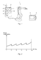
- FIG. 1 shows an example of an industrial robot according to an embodiment of the invention.
- the robot includes a manipulator 1 and a control unit 2 for controlling the motions of the manipulator.
- the control unit includes at least one processor, memory storage, communication units, drive units and other hardware and software necessary for controlling the robot. Motors of the manipulator are supplied with power from the drives of the robot controller.
- the robot further includes a portable operating device 3, hereafter called a TPU, for teaching and manually operating the robot.
- the TPU is in communication with the control unit, ether wirelessly or through a cable.
- the TPU is provided with a display unit 4.
- the control unit 2 can also be in communication with a head control system, not shown in the figure.
- the power supply to the robot is measured by means of a power meter 5.
- the power meter 5 is arranged on the incoming power cable to the robot. If the robot is supplied with from power from more than one power cable, each cable can be provided with a power meter.
- the resulting power measurements are supplied to the robot controller.
- the power measurements are stored and further processed by the robot controller.
- the resulting power measurements can be supplied to, stored, and further processed by an external computer, for example the head control system.
- the power is measured at any other place in the robot, for example at the drives, or another parameter, such as the current, is measured and the power consumption is calculated based on the measured quantity.
- the power consumption can be calculated continuously in the robot system during production and can, for example, be different kinds of measures related to the energy consumption to move the robot arm, such as energy consumed during a time period, energy consumed during one production cycle, or parts of the total energy consumed, such as friction energy.
- measures related to the energy consumption to move the robot arm such as energy consumed during a time period, energy consumed during one production cycle, or parts of the total energy consumed, such as friction energy.
- the robot controller or alternatively the external computer, is provided with computing means configured to determine whether the energy consumption has increased more than a permitted value, and to initiate an action if the energy consumption has increased more than the permitted value.
- the computing means includes suitable hardware and software for determining whether the energy consumption has increased more than a permitted value.
- the energy consumed by the robot during a certain time period is repeatably determined.
- the determined energy consumption is stored, and the energy consumed by the robot during a present time period is compared with the energy consumed by the robot during a previous time period, preferably the preceding time period, and based on the result of the comparison it is determined whether the total energy consumption has increased more than the permitted value.
- the default value for the permitted value of the power increase is, for example, set by the robot supplier, but can possibly be changed by the robot user.
- the present environmental impact of the robot is continuously calculated based on the power consumption of the robot, and the calculated environmental impact is made available to a robot user.
- the robot user can access this information by the TPU.
- Information on the present environmental impact can be transferred to the head control unit.
- the power consumption of the robot is continuously displayed, for example on the TPU.
- the power consumption per unit of time is presented. This embodiment makes it possible for the user to compare the power consumption for a plurality of robots.
- the robot controller initiates one or more actions.
- One possible action is to provide a warning to the robot user when the environmental impact of the robot has increased above the permitted value. This warning is, for example, displayed on the TPU. The warning can also be transferred to the head control system.
- control unit 2 includes a data processing unit 6, such as a CPU, a first data storage 7 for storing the measured power consumption of the robot, a computing module 8 configured to determine whether the energy consumption has increased more than a permitted value, and to initiate an action if the energy consumption has increased more than the permitted value, and second data storage 9 for storing the environmental impact of different types of service actions for the robot.
- a data processing unit 6 such as a CPU
- first data storage 7 for storing the measured power consumption of the robot
- computing module 8 configured to determine whether the energy consumption has increased more than a permitted value, and to initiate an action if the energy consumption has increased more than the permitted value
- second data storage 9 for storing the environmental impact of different types of service actions for the robot.
- the control unit 2 further includes diagnostic means 10 for determining the reason for the increased power consumption upon detecting that the energy consumption has increased more than the permitted value, and for determining one or more suitable service actions for the robot based on the determined reason for the increased power consumption.
- the computing module 8 is further configured to calculate with respect to the environmental impact an optimal service interval for the robot based on the stored power consumption, the environmental impact of the determined service actions, and an optimization criterion.
- Figure 2 shows an example of the power consumption of a robot during its lifetime.
- Service is made on the robot at the points in time denoted t 1 , t 2 , t 3 , and t 4 .
- making a service on the robot reduces the power consumption.
- the power consumtion after a service occasion is somewhat higher than the power consumption after the last service occasion, and accordingly the power consumption during the life-time of the robot increases.
- Figure 3 shows an example of the environmental impact as a function of time in dependence on the length of the service intervals.
- Curve A shows the environmental impact if service is made on the robot with a service interval of one week.
- Curve B shows the environmental impact if service is made on the robot with a service interval of 30 weeks.
- Curve C shows the environmental impact if service is made on the robot with a service interval of 10 weeks.
- Curve D shows the environmental impact if service is made on the robot with a service interval of 5 weeks.
- an optimal service interval is calculated for the robot.
- the environmental impact of different types of service actions, such as change of oil, for the robot is estimated and stored beforehand, for example, in the control unit.
- the reason for the increased power consumption is determined by means of an automatic diagnostic method
- one or more suitable service actions for the robot is automatically determined based on the determined reason for the increased power consumption
- an optimal service interval for the robot with respect to the environmental impact is calculated based on the stored power consumption, the stored environmental impact of the determined service actions, and an optimization criterion.
- Those steps are, for example, carried out by software stored in the control unit and run on hardware of the control unit.
- an optimal service interval When an optimal service interval has been calculated, it is possible to calculate an optimal point in time for carrying out the next service for the robot with respect to the environmental impact based on the calculated optimal service interval.
- the next service for the robot with respect to the environmental impact is presented to the user or at least made available to the user.
- T i +1 - T i the service interval
- N is equal to the lifetime T life of the robot divided by the service interval T i +1 - T i
- EI service is the environmental impact of the service performed.
- K is a constant reflecting what kind of source is used to generate the energy. The higher value on k the more is the impact on the environment. For simplicity it is assumed that the power consumption of the robot after a service occasion always is the same, and not increasing as in reality.
- the optimal solution can then be found by minimizing EI tot with respect to N.
Landscapes
- Engineering & Computer Science (AREA)
- Robotics (AREA)
- Mechanical Engineering (AREA)
- Human Computer Interaction (AREA)
- Manufacturing & Machinery (AREA)
- Physics & Mathematics (AREA)
- General Physics & Mathematics (AREA)
- Automation & Control Theory (AREA)
- Manipulator (AREA)
Abstract
The present invention relates to an industrial robot capable of supervising its environmental impact, wherein the robot comprises: recording means (5,7) configured to record the power consumption of the robot, and computing means (8) configured to determine whether the energy consumption has increased more than a permitted value, and to initiate an action if the energy consumption has increased more than the permitted value.
Description
- The present invention relates to an industrial robot capable of supervising its environmental impact. The invention also relates to a method for supervising the environmental impact of an industrial robot.
- Industrial robots are today used throughout almost all branches of industrial applications. As an asset among others, the robots contribute to the total environment impact of the plant. The environmental impact exerted by robot system is not constant during the robot life cycle. The impact on the environment will increase during the robot life cycle, since different components of the robot will age and wear down during the life cycle of the robot. The robots are subjected to services with regular service intervals during its life time. When the service has been carried out, the power consumption of the robot is reduced. However, some types of service, such as change of oil, also have an impact on the environment. Traditionally, robot systems have no functionality to estimate the impact on the environment of its usage.
- One object of the present invention is to provide a method for supervising the environmental impact of an industrial robot.
- This object is achieved by a method as defined in claim 1.
- Such a method comprises: continuously recording the power consumption of the robot, determining whether the energy consumption has increased more than a permitted value, and initiating an action if the energy consumption has increased more than the permitted value.
- The power consumption of the robot is the largest environmental impact of the robot. Thus, according to the invention, the power consumption of the robot is recorded and if the energy consumption has increased more than a permitted value an action is initiated. For example, it is possible to give warnings to the user if the power consumption, and accordingly the environmental impact, increases. The user can then determine what actions to be taken in order to decrease the environmental impact of, such as carrying out service on the robot or replacing the robot with a new robot. The power consumption is, for example, recorded as a function of time. The power consumption of the robot can be determined based on power measurements, or on measurement of any other quantity related to the power consumption, such as the current. Although it is possible to calculate the power consumption based on motor references, such as desired motor torque, calculated by the control unit of the robot, it is preferable to use measured values, since they include information on an increase of the power consumption due to wear of the robot, and possibly faulty components of the robot causing an increase in the power consumption.
- Further, the recorded power consumption data can be used to identify potential improvements as to how the robot is used and propose changes in the installation that will decrease the environmental impact.
- In this context the wordings power consumption and energy consumption are used synonymously.
- When the robot starts to wear, the power consumption and accordingly the environmental impact will increase. Making a service will reduce the power consumption to a normal level. However, making a service will have an environmental impact in itself. According to an embodiment of the invention, the method further comprises storing the environmental impact of different types of service actions for the robot, and said actions include: determining the reason for the increased power consumption by means of an automatic diagnostic method, automatically determining one or more suitable service actions for the robot based on the determined reason for the increased power consumption, and calculating with respect to the environmental impact an optimal service interval for the robot based on the stored power consumption, the environmental impact of the determined service actions, and an optimization criterion. This embodiment makes it possible to automatically calculate an optimal service interval from an environmental point of view.
- The power consumption of the robot is recorded and the recorded data is used to determine an optimal service interval with respect to the environmental impact. Also the environmental impact of the service is considered when determining the optimal service interval. The types of services are, for example, oil change or replacement of different components of the robot by spare parts. Diagnostic methods which today are used for condition-based maintenance in the robot system can be used to supervise environmental impact of the robot system.
- According to an embodiment of the invention, the method further comprises calculating with respect to the environmental impact an optimal point in time for carrying out the next service for the robot based on the calculated optimal service interval. This embodiment makes it possible to have varying time intervals for the services, each time interval being optimized with regard to the environmental impact.
- According to an embodiment of the invention, the action includes providing a warning to the robot user when the environmental impact of the robot has increased above the permitted value. This embodiment makes it possible to give a warning to the user when a significant change of the environmental impact has occurred.
- According to an embodiment of the invention, the method comprises calculating the present environmental impact of the robot based on the power consumption of the robot and making the calculated present environmental impact accessible for a robot user. For example, the environmental impact is presented in the form of CO2 equivalents as a function of time. The environmental impact is, for example, calculated by making an LCA (Life cycle Analyze) analysis of the recorded power consumption. The present environmental impact can also be made available to an overhead control system via a suitable interface. The warning mentioned above can be given via the same interface and/or via a graphical interface of the robot.
- According to an embodiment of the invention, the method comprises continuously displaying the power consumption of the robot. A robot comprises a manipulator and a control unit controlling the motions of the manipulator. Preferably, the total power consumption of the robot is determined and displayed, such as the power consumption of the manipulator as well as the robot controller. Suitably, the power consumption as a function of time is displayed to the user. This embodiment makes it possible for the user to supervise the power consumption of the robot and to compare the power consumption of different robots.
- The method according to the invention, as defined in the appended set of method claims, is suitable for execution by a computer program having instructions corresponding to the steps in the inventive method when run on a processor unit. Preferably, the method is carried out by the robot controller.
- Another object of the present invention is to provide an industrial robot capable of supervising its environmental impact.
- This object is achieved by a robot as defined in
claim 8. - The invention will now be explained more closely by the description of different embodiments of the invention and with reference to the appended figures.
- Fig. 1
- shows an example of an industrial robot according to an embodiment of the invention.
- Fig. 2
- shows an example of the power consumption of a robot during its lifetime.
- Fig. 3
- shows an example of the environmental impact as a function of time in dependence on the length of the service interval.
-
Figure 1 shows an example of an industrial robot according to an embodiment of the invention. The robot includes a manipulator 1 and acontrol unit 2 for controlling the motions of the manipulator. The control unit includes at least one processor, memory storage, communication units, drive units and other hardware and software necessary for controlling the robot. Motors of the manipulator are supplied with power from the drives of the robot controller. The robot further includes aportable operating device 3, hereafter called a TPU, for teaching and manually operating the robot. The TPU is in communication with the control unit, ether wirelessly or through a cable. The TPU is provided with adisplay unit 4. Thecontrol unit 2 can also be in communication with a head control system, not shown in the figure. - In this embodiment of the invention the power supply to the robot is measured by means of a
power meter 5. Thepower meter 5 is arranged on the incoming power cable to the robot. If the robot is supplied with from power from more than one power cable, each cable can be provided with a power meter. In this embodiment of the invention, the resulting power measurements are supplied to the robot controller. The power measurements are stored and further processed by the robot controller. Alternatively, the resulting power measurements can be supplied to, stored, and further processed by an external computer, for example the head control system. Alternatively, the power is measured at any other place in the robot, for example at the drives, or another parameter, such as the current, is measured and the power consumption is calculated based on the measured quantity. The power consumption can be calculated continuously in the robot system during production and can, for example, be different kinds of measures related to the energy consumption to move the robot arm, such as energy consumed during a time period, energy consumed during one production cycle, or parts of the total energy consumed, such as friction energy. Several of these measures are used today, but not with the aim to give measures of environmental impact, but for fault diagnostics and motion control. - The robot controller, or alternatively the external computer, is provided with computing means configured to determine whether the energy consumption has increased more than a permitted value, and to initiate an action if the energy consumption has increased more than the permitted value. The computing means includes suitable hardware and software for determining whether the energy consumption has increased more than a permitted value. The energy consumed by the robot during a certain time period is repeatably determined. The determined energy consumption is stored, and the energy consumed by the robot during a present time period is compared with the energy consumed by the robot during a previous time period, preferably the preceding time period, and based on the result of the comparison it is determined whether the total energy consumption has increased more than the permitted value. The default value for the permitted value of the power increase is, for example, set by the robot supplier, but can possibly be changed by the robot user.
- In an alternative embodiment of the invention, the present environmental impact of the robot is continuously calculated based on the power consumption of the robot, and the calculated environmental impact is made available to a robot user. For example, the robot user can access this information by the TPU. Information on the present environmental impact can be transferred to the head control unit. In an alternative embodiment of the invention, the power consumption of the robot is continuously displayed, for example on the TPU. Suitably, the power consumption per unit of time is presented. This embodiment makes it possible for the user to compare the power consumption for a plurality of robots.
- If the energy consumption has increased more than the permitted value, the robot controller initiates one or more actions. One possible action is to provide a warning to the robot user when the environmental impact of the robot has increased above the permitted value. This warning is, for example, displayed on the TPU. The warning can also be transferred to the head control system.
- In this example the
control unit 2 includes adata processing unit 6, such as a CPU, afirst data storage 7 for storing the measured power consumption of the robot, acomputing module 8 configured to determine whether the energy consumption has increased more than a permitted value, and to initiate an action if the energy consumption has increased more than the permitted value, and second data storage 9 for storing the environmental impact of different types of service actions for the robot. - The
control unit 2 further includes diagnostic means 10 for determining the reason for the increased power consumption upon detecting that the energy consumption has increased more than the permitted value, and for determining one or more suitable service actions for the robot based on the determined reason for the increased power consumption. Thecomputing module 8 is further configured to calculate with respect to the environmental impact an optimal service interval for the robot based on the stored power consumption, the environmental impact of the determined service actions, and an optimization criterion. -
Figure 2 shows an example of the power consumption of a robot during its lifetime. When the robot starts to wear, the power consumption, and accordingly the environmental impact, will increase. Service is made on the robot at the points in time denoted t1, t2, t3, and t4. As seen from the figure, making a service on the robot reduces the power consumption. In practice, the power consumtion after a service occasion is somewhat higher than the power consumption after the last service occasion, and accordingly the power consumption during the life-time of the robot increases. - However, making a service will have an environmental impact in itself.
-
Figure 3 shows an example of the environmental impact as a function of time in dependence on the length of the service intervals. Curve A shows the environmental impact if service is made on the robot with a service interval of one week. Curve B shows the environmental impact if service is made on the robot with a service interval of 30 weeks. Curve C shows the environmental impact if service is made on the robot with a service interval of 10 weeks. Curve D shows the environmental impact if service is made on the robot with a service interval of 5 weeks. When a service is made, the power consumption is decreased, but the environmental impact due to the service is increased. In total, the environmental impact at the point in time of the service will increase, but soon after the service the environmental impact will be lower. During the entire life time of the robot the environmental impact will increase. As seen from the figure, the environmental impact is lowest if the service is made with a service interval of 5 weeks. - According to an embodiment of the invention, an optimal service interval is calculated for the robot. The environmental impact of different types of service actions, such as change of oil, for the robot is estimated and stored beforehand, for example, in the control unit. When it is determined that the power consumption has increased more than the permitted value, the following steps are carried out: the reason for the increased power consumption is determined by means of an automatic diagnostic method, one or more suitable service actions for the robot is automatically determined based on the determined reason for the increased power consumption, and an optimal service interval for the robot with respect to the environmental impact is calculated based on the stored power consumption, the stored environmental impact of the determined service actions, and an optimization criterion. Those steps are, for example, carried out by software stored in the control unit and run on hardware of the control unit. In the prior art numerous diagnostic methods are known, which can be used for determining the reason for an increased power consumption. The aim of the known diagnostic methods is fault diagnostics for the robot and not to reduce the environmental impact of the robot. Examples of diagnostic methods which can be used to determine suitable service to be done on the robot is disclosed in European patent application No.
06125771 06125079 06125771 07102279 - When an optimal service interval has been calculated, it is possible to calculate an optimal point in time for carrying out the next service for the robot with respect to the environmental impact based on the calculated optimal service interval. The next service for the robot with respect to the environmental impact is presented to the user or at least made available to the user.
- In the following, one example of a method for calculating an optimal service interval for the robot is described.
- Using the recorded data of energy consumption, a function W(t) (power consumption) is fitted to the experimental data. Making a service will eliminate the effect of wear on the power consumption, hence the power consumption after a service at a time T is equal to W(t-T). The environmental impact is given by the consumed energy multiplied by some constant k reflecting what kind of source is used to generate the energy (water, coal, wind, nuclear etc) and the number and types of service actions. The total environmental impact EItot can be written as:

Where T i+1 - Ti is the service interval,
N is equal to the lifetime Tlife of the robot divided by the service interval T i+1 - Ti,
EIservice is the environmental impact of the service performed.
K is a constant reflecting what kind of source is used to generate the energy. The higher value on k the more is the impact on the environment. For simplicity it is assumed that the power consumption of the robot after a service occasion always is the same, and not increasing as in reality. - Formula 1 is derived by the following:


The optimal solution can then be found by minimizing EItot with respect to N. The optimization criterion can be written:
- This approach is exemplified using the example shown in
figure 3 . A function W(t) is fitted to the measured power data.Figure 3 is based on a case in which W(t) = 1 + 0.1t. The curve B is the integral of W(t) = 1 + 0.1t.
In this example it is assumed that:
k = 1
EIservice =1,5 (This is an estimate of the environmental impact of a standard service performed at regular intervals)
Tlife = 30 weeks
dEItot /dt = 0 gives an optimal service interval of 5,5 weeks. - Knowing the point in time for the last service occasion, it is easy to calculate the point in time for the next service occasion based on the calculated optimal service interval.
Claims (12)
- A method for supervising the environmental impact of an industrial robot (1), wherein the method comprises:continuously recording the power consumption of the robot,determining whether the energy consumption has increased more than a permitted value, andinitiating an action if the energy consumption has increased more than the permitted value.
- The method according to any of the previous claims, wherein the method further comprises storing the environmental impact of different types of service actions for the robot, and said action includes:determining the reason for the increased power consumption by means of an automatic diagnostic method,automatically determining one or more suitable service actions for the robot based on the determined reason for the increased power consumption, andcalculating with respect to the environmental impact an optimal service interval for the robot based on the stored power consumption, the environmental impact of the determined service actions, and an optimization criterion.
- The method according to claim 2, wherein the method further comprises calculating with respect to the environmental impact an optimal point in time for carrying out the next service for the robot based on the calculated optimal service interval.
- The method according to any of the previous claims, wherein said action includes providing a warning to the robot user when the environmental impact of the robot has increased above the permitted value.
- The method according to any of the previous claims, wherein the method comprises calculating the present environmental impact of the robot based on the power consumption of the robot and making the calculated present environmental impact accessible for a robot user.
- The method according to any of the previous claims, wherein the method comprises continuously displaying the power consumption of the robot.
- The method according to any of the previous claims, wherein the method comprises:repeatably determining the energy consumed by the robot during a certain time period,storing the determined energy consumption, andcomparing the energy consumed by the robot during the present time period with the energy consumed by the robot during a previous time period, and based thereon determining whether the total energy consumption has increased more than the permitted value.
- An industrial robot capable of supervising its environmental impact, wherein the robot comprises:recording means (5,7) configured to record the power consumption of the robot, andcomputing means (8) configured to determine whether the energy consumption has increased more than a permitted value, and to initiate an action if the energy consumption has increased more than the permitted value.
- The robot according to claim 8, wherein the robot comprises:a data storage (9) for storing the environmental impact of different types of service actions for the robot, anddiagnostic means (10) for determining the reason for the increased power consumption upon detecting that the energy consumption has increased more than the permitted value, and for determining one or more suitable service actions for the robot based on the determined reason for the increased power consumption, and said computing means (8) is configured to calculate with respect to the environmental impact an optimal service interval for the robot based on the stored power consumption, the environmental impact of the determined service actions, and an optimization criterion.
- The robot according to according to claim 8 or 9, wherein said computing means (8) is configured to provide a warning when the environmental impact of the robot has increased above the permitted value.
- The robot according to according to any of claims 8-10, wherein said computing means (8) is configured to calculate the present environmental impact of the robot based on the recorded power consumption of the robot and the robot is configured to make the calculated present environmental impact accessible for a robot user.
- The robot according to any of claims 8-11, wherein the robot is configured to for continuously display the power consumption of the robot.
Priority Applications (1)
| Application Number | Priority Date | Filing Date | Title |
|---|---|---|---|
| EP08156349A EP2082851A1 (en) | 2008-05-16 | 2008-05-16 | An industrial robot capable of supervising its environmental impact and a method thereof |
Applications Claiming Priority (1)
| Application Number | Priority Date | Filing Date | Title |
|---|---|---|---|
| EP08156349A EP2082851A1 (en) | 2008-05-16 | 2008-05-16 | An industrial robot capable of supervising its environmental impact and a method thereof |
Publications (1)
| Publication Number | Publication Date |
|---|---|
| EP2082851A1 true EP2082851A1 (en) | 2009-07-29 |
Family
ID=39791398
Family Applications (1)
| Application Number | Title | Priority Date | Filing Date |
|---|---|---|---|
| EP08156349A Withdrawn EP2082851A1 (en) | 2008-05-16 | 2008-05-16 | An industrial robot capable of supervising its environmental impact and a method thereof |
Country Status (1)
| Country | Link |
|---|---|
| EP (1) | EP2082851A1 (en) |
Cited By (6)
| Publication number | Priority date | Publication date | Assignee | Title |
|---|---|---|---|---|
| US7912584B2 (en) * | 2009-05-27 | 2011-03-22 | Fanuc Ltd | Power consumption estimation apparatus |
| WO2014012304A1 (en) * | 2012-07-20 | 2014-01-23 | 重庆市电力公司电力科学研究院 | Electrical energy meter verification system and robot therefor |
| WO2016091678A1 (en) * | 2014-12-09 | 2016-06-16 | Kuka Systems Gmbh | Method for monitoring at least one industrial robot, industrial robot, and system having a plurality of industrial robots |
| WO2017070872A1 (en) * | 2015-10-28 | 2017-05-04 | 西门子公司 | Method and apparatus for abnormality detection |
| CN109664302A (en) * | 2019-01-25 | 2019-04-23 | 北京猎户星空科技有限公司 | A kind of robot control method, device, medium and equipment |
| CN114734418A (en) * | 2022-04-29 | 2022-07-12 | 周奇 | Multi-track inspection robot |
Citations (8)
| Publication number | Priority date | Publication date | Assignee | Title |
|---|---|---|---|---|
| EP0269373A2 (en) * | 1986-11-20 | 1988-06-01 | Unimation Inc. | Multiaxis robot control having protection system with energy and backup velocity monitoring |
| EP0632353A1 (en) * | 1993-06-29 | 1995-01-04 | Elbit Ltd. | System and method for measuring the operation of a device |
| EP0842006A1 (en) * | 1995-08-04 | 1998-05-20 | Tri-Way Machine Ltd. | Tool condition monitoring system |
| US20030171851A1 (en) * | 2002-03-08 | 2003-09-11 | Peter J. Brickfield | Automatic energy management and energy consumption reduction, especially in commercial and multi-building systems |
| US20050143876A1 (en) * | 2003-06-26 | 2005-06-30 | Yamaha Corporation | Energy-saving evaluation apparatus, ecological driving evaluation apparatus, energy saving evaluation system, ecological driving evaluation system and method thereof |
| EP1927440A1 (en) | 2006-11-30 | 2008-06-04 | Abb Research Ltd. | Method and device for monitoring the condition of an industrial robot |
| EP1932629A1 (en) | 2006-12-11 | 2008-06-18 | Abb Research Ltd. | A method and a control system for monitoring the condition of an industrial robot |
| EP1958738A1 (en) | 2007-02-13 | 2008-08-20 | Abb Research Ltd. | Remote diagnostic system for robots |
-
2008
- 2008-05-16 EP EP08156349A patent/EP2082851A1/en not_active Withdrawn
Patent Citations (8)
| Publication number | Priority date | Publication date | Assignee | Title |
|---|---|---|---|---|
| EP0269373A2 (en) * | 1986-11-20 | 1988-06-01 | Unimation Inc. | Multiaxis robot control having protection system with energy and backup velocity monitoring |
| EP0632353A1 (en) * | 1993-06-29 | 1995-01-04 | Elbit Ltd. | System and method for measuring the operation of a device |
| EP0842006A1 (en) * | 1995-08-04 | 1998-05-20 | Tri-Way Machine Ltd. | Tool condition monitoring system |
| US20030171851A1 (en) * | 2002-03-08 | 2003-09-11 | Peter J. Brickfield | Automatic energy management and energy consumption reduction, especially in commercial and multi-building systems |
| US20050143876A1 (en) * | 2003-06-26 | 2005-06-30 | Yamaha Corporation | Energy-saving evaluation apparatus, ecological driving evaluation apparatus, energy saving evaluation system, ecological driving evaluation system and method thereof |
| EP1927440A1 (en) | 2006-11-30 | 2008-06-04 | Abb Research Ltd. | Method and device for monitoring the condition of an industrial robot |
| EP1932629A1 (en) | 2006-12-11 | 2008-06-18 | Abb Research Ltd. | A method and a control system for monitoring the condition of an industrial robot |
| EP1958738A1 (en) | 2007-02-13 | 2008-08-20 | Abb Research Ltd. | Remote diagnostic system for robots |
Cited By (9)
| Publication number | Priority date | Publication date | Assignee | Title |
|---|---|---|---|---|
| US7912584B2 (en) * | 2009-05-27 | 2011-03-22 | Fanuc Ltd | Power consumption estimation apparatus |
| WO2014012304A1 (en) * | 2012-07-20 | 2014-01-23 | 重庆市电力公司电力科学研究院 | Electrical energy meter verification system and robot therefor |
| WO2016091678A1 (en) * | 2014-12-09 | 2016-06-16 | Kuka Systems Gmbh | Method for monitoring at least one industrial robot, industrial robot, and system having a plurality of industrial robots |
| WO2017070872A1 (en) * | 2015-10-28 | 2017-05-04 | 西门子公司 | Method and apparatus for abnormality detection |
| CN108027298A (en) * | 2015-10-28 | 2018-05-11 | 西门子公司 | A method and device for anomaly detection |
| US10974383B2 (en) | 2015-10-28 | 2021-04-13 | Siemens Aktiengesellschaft | Method and apparatus for abnormality detection |
| CN109664302A (en) * | 2019-01-25 | 2019-04-23 | 北京猎户星空科技有限公司 | A kind of robot control method, device, medium and equipment |
| CN114734418A (en) * | 2022-04-29 | 2022-07-12 | 周奇 | Multi-track inspection robot |
| CN114734418B (en) * | 2022-04-29 | 2023-09-19 | 瓦力机器人科技(唐山)有限公司 | Multi-track inspection robot |
Similar Documents
| Publication | Publication Date | Title |
|---|---|---|
| US10527520B2 (en) | Operating wind motors and determining their remaining useful life | |
| JP6569927B1 (en) | Abnormality determination system, motor control device, and abnormality determination device | |
| Alaswad et al. | A review on condition-based maintenance optimization models for stochastically deteriorating system | |
| CN112727965B (en) | Fault monitoring method and device for brake of coal mining machine | |
| EP2082851A1 (en) | An industrial robot capable of supervising its environmental impact and a method thereof | |
| JP5369246B1 (en) | Abnormal sign diagnostic apparatus and abnormal sign diagnostic method | |
| EP2836881B1 (en) | Embedded prognostics on plc platforms for equipment condition monitoring, diagnosis and time-to-failure/service prediction | |
| RU2757436C2 (en) | Device and method for monitoring indications of malfunction from vehicle, computer-readable media | |
| KR20170093908A (en) | Robot maintenance assist device and method | |
| EP1538503A1 (en) | Distributed power generation plant automated event assessment and mitigation plan determination process | |
| CN112987682B (en) | Control method, control device and mechanical equipment | |
| CN107272586A (en) | Rote learning device, learning by rote, failure precognition apparatus and system | |
| AU2022246525A1 (en) | Systems and methods for automatically scheduling maintenance | |
| JP2012141980A (en) | Systems and methods for use in correcting predicted failure in production process | |
| JP2016038657A (en) | Diagnosis support system and diagnosis support method | |
| US11131977B2 (en) | Data collection system and method | |
| CN102819245B (en) | Method for monitoring installation | |
| WO2018155529A1 (en) | Aircraft management device, method, and program | |
| US20140361978A1 (en) | Portable computer monitoring | |
| CN119335990A (en) | Refrigeration room control system evaluation and optimization method, system, medium, program product and terminal based on reinforcement learning | |
| KR20200045980A (en) | Method and system for direct estimation of exact power in real-time | |
| KR102484041B1 (en) | System-level prognostics apparatus and method thereof | |
| CN111196546A (en) | Detection method, device and system for escalator drive chain abnormity and computer equipment | |
| CN120013217B (en) | Hydropower plant equipment spot inspection system optimization method and system | |
| WO2026069281A1 (en) | Condition monitoring |
Legal Events
| Date | Code | Title | Description |
|---|---|---|---|
| PUAI | Public reference made under article 153(3) epc to a published international application that has entered the european phase |
Free format text: ORIGINAL CODE: 0009012 |
|
| AK | Designated contracting states |
Kind code of ref document: A1 Designated state(s): AT BE BG CH CY CZ DE DK EE ES FI FR GB GR HR HU IE IS IT LI LT LU LV MC MT NL NO PL PT RO SE SI SK TR |
|
| AX | Request for extension of the european patent |
Extension state: AL BA MK RS |
|
| AKX | Designation fees paid | ||
| REG | Reference to a national code |
Ref country code: DE Ref legal event code: 8566 |
|
| STAA | Information on the status of an ep patent application or granted ep patent |
Free format text: STATUS: THE APPLICATION IS DEEMED TO BE WITHDRAWN |
|
| 18D | Application deemed to be withdrawn |
Effective date: 20100130 |