EP2082670A1 - Exchangeable filter for beverage production device and beverage production device comprising such filter - Google Patents
Exchangeable filter for beverage production device and beverage production device comprising such filter Download PDFInfo
- Publication number
- EP2082670A1 EP2082670A1 EP08100897A EP08100897A EP2082670A1 EP 2082670 A1 EP2082670 A1 EP 2082670A1 EP 08100897 A EP08100897 A EP 08100897A EP 08100897 A EP08100897 A EP 08100897A EP 2082670 A1 EP2082670 A1 EP 2082670A1
- Authority
- EP
- European Patent Office
- Prior art keywords
- filter
- water
- card
- filter membrane
- membrane
- Prior art date
- Legal status (The legal status is an assumption and is not a legal conclusion. Google has not performed a legal analysis and makes no representation as to the accuracy of the status listed.)
- Withdrawn
Links
- 235000013361 beverage Nutrition 0.000 title description 5
- 238000004519 manufacturing process Methods 0.000 title description 4
- XLYOFNOQVPJJNP-UHFFFAOYSA-N water Substances O XLYOFNOQVPJJNP-UHFFFAOYSA-N 0.000 claims abstract description 158
- 239000012528 membrane Substances 0.000 claims abstract description 144
- 239000000203 mixture Substances 0.000 claims abstract description 37
- 235000016709 nutrition Nutrition 0.000 claims abstract description 36
- 239000004615 ingredient Substances 0.000 claims abstract description 20
- 230000000845 anti-microbial effect Effects 0.000 claims abstract description 19
- 230000003993 interaction Effects 0.000 claims abstract description 6
- 238000004891 communication Methods 0.000 claims abstract description 5
- 230000000295 complement effect Effects 0.000 claims abstract description 3
- 239000008400 supply water Substances 0.000 claims abstract description 3
- 238000007789 sealing Methods 0.000 claims description 46
- 235000013350 formula milk Nutrition 0.000 claims description 27
- 239000011148 porous material Substances 0.000 claims description 17
- 239000004033 plastic Substances 0.000 claims description 9
- 238000011144 upstream manufacturing Methods 0.000 claims description 9
- 235000013305 food Nutrition 0.000 claims description 3
- 239000007769 metal material Substances 0.000 claims description 3
- 238000011012 sanitization Methods 0.000 claims description 2
- 239000007788 liquid Substances 0.000 description 21
- 238000001914 filtration Methods 0.000 description 15
- 238000002360 preparation method Methods 0.000 description 15
- 238000000034 method Methods 0.000 description 12
- 244000052769 pathogen Species 0.000 description 12
- 238000002347 injection Methods 0.000 description 11
- 239000007924 injection Substances 0.000 description 11
- 230000007246 mechanism Effects 0.000 description 9
- 239000000463 material Substances 0.000 description 7
- 230000033001 locomotion Effects 0.000 description 6
- 230000008569 process Effects 0.000 description 6
- 238000011109 contamination Methods 0.000 description 5
- 239000012530 fluid Substances 0.000 description 5
- 239000000843 powder Substances 0.000 description 5
- 241000894006 Bacteria Species 0.000 description 4
- OKTJSMMVPCPJKN-UHFFFAOYSA-N Carbon Chemical compound [C] OKTJSMMVPCPJKN-UHFFFAOYSA-N 0.000 description 4
- 208000015181 infectious disease Diseases 0.000 description 4
- 239000000047 product Substances 0.000 description 4
- 210000000987 immune system Anatomy 0.000 description 3
- 230000004044 response Effects 0.000 description 3
- 239000000243 solution Substances 0.000 description 3
- 241000283690 Bos taurus Species 0.000 description 2
- 206010020751 Hypersensitivity Diseases 0.000 description 2
- 241000700605 Viruses Species 0.000 description 2
- 108010046377 Whey Proteins Proteins 0.000 description 2
- 102000007544 Whey Proteins Human genes 0.000 description 2
- 230000007815 allergy Effects 0.000 description 2
- 239000004411 aluminium Substances 0.000 description 2
- 229910052782 aluminium Inorganic materials 0.000 description 2
- XAGFODPZIPBFFR-UHFFFAOYSA-N aluminium Chemical compound [Al] XAGFODPZIPBFFR-UHFFFAOYSA-N 0.000 description 2
- 230000008859 change Effects 0.000 description 2
- 230000001010 compromised effect Effects 0.000 description 2
- 238000004090 dissolution Methods 0.000 description 2
- 230000000694 effects Effects 0.000 description 2
- 238000011010 flushing procedure Methods 0.000 description 2
- 239000011888 foil Substances 0.000 description 2
- 235000020256 human milk Nutrition 0.000 description 2
- 238000003780 insertion Methods 0.000 description 2
- 230000037431 insertion Effects 0.000 description 2
- 238000012423 maintenance Methods 0.000 description 2
- 244000005700 microbiome Species 0.000 description 2
- 238000003825 pressing Methods 0.000 description 2
- 238000010926 purge Methods 0.000 description 2
- 230000001960 triggered effect Effects 0.000 description 2
- 208000035143 Bacterial infection Diseases 0.000 description 1
- 240000004808 Saccharomyces cerevisiae Species 0.000 description 1
- 208000036142 Viral infection Diseases 0.000 description 1
- 239000005862 Whey Substances 0.000 description 1
- 230000001580 bacterial effect Effects 0.000 description 1
- 208000022362 bacterial infectious disease Diseases 0.000 description 1
- 230000004888 barrier function Effects 0.000 description 1
- 239000002775 capsule Substances 0.000 description 1
- 239000005018 casein Substances 0.000 description 1
- BECPQYXYKAMYBN-UHFFFAOYSA-N casein, tech. Chemical compound NCCCCC(C(O)=O)N=C(O)C(CC(O)=O)N=C(O)C(CCC(O)=N)N=C(O)C(CC(C)C)N=C(O)C(CCC(O)=O)N=C(O)C(CC(O)=O)N=C(O)C(CCC(O)=O)N=C(O)C(C(C)O)N=C(O)C(CCC(O)=N)N=C(O)C(CCC(O)=N)N=C(O)C(CCC(O)=N)N=C(O)C(CCC(O)=O)N=C(O)C(CCC(O)=O)N=C(O)C(COP(O)(O)=O)N=C(O)C(CCC(O)=N)N=C(O)C(N)CC1=CC=CC=C1 BECPQYXYKAMYBN-UHFFFAOYSA-N 0.000 description 1
- 235000021240 caseins Nutrition 0.000 description 1
- 235000013339 cereals Nutrition 0.000 description 1
- 235000020247 cow milk Nutrition 0.000 description 1
- 230000007812 deficiency Effects 0.000 description 1
- 230000003111 delayed effect Effects 0.000 description 1
- 230000001419 dependent effect Effects 0.000 description 1
- 238000013461 design Methods 0.000 description 1
- 230000006866 deterioration Effects 0.000 description 1
- 238000011161 development Methods 0.000 description 1
- 201000010099 disease Diseases 0.000 description 1
- 208000037265 diseases, disorders, signs and symptoms Diseases 0.000 description 1
- 230000035622 drinking Effects 0.000 description 1
- 238000005516 engineering process Methods 0.000 description 1
- 238000010438 heat treatment Methods 0.000 description 1
- 210000004251 human milk Anatomy 0.000 description 1
- 235000014666 liquid concentrate Nutrition 0.000 description 1
- 239000011859 microparticle Substances 0.000 description 1
- 235000013336 milk Nutrition 0.000 description 1
- 210000004080 milk Anatomy 0.000 description 1
- 239000008267 milk Substances 0.000 description 1
- 238000012986 modification Methods 0.000 description 1
- 230000004048 modification Effects 0.000 description 1
- 235000015097 nutrients Nutrition 0.000 description 1
- 239000005022 packaging material Substances 0.000 description 1
- 230000002572 peristaltic effect Effects 0.000 description 1
- 230000035699 permeability Effects 0.000 description 1
- 229920000642 polymer Polymers 0.000 description 1
- 235000014483 powder concentrate Nutrition 0.000 description 1
- 238000012545 processing Methods 0.000 description 1
- 230000000750 progressive effect Effects 0.000 description 1
- 235000004252 protein component Nutrition 0.000 description 1
- 235000018102 proteins Nutrition 0.000 description 1
- 102000004169 proteins and genes Human genes 0.000 description 1
- 108090000623 proteins and genes Proteins 0.000 description 1
- 238000004064 recycling Methods 0.000 description 1
- 239000003566 sealing material Substances 0.000 description 1
- 238000001179 sorption measurement Methods 0.000 description 1
- 235000013322 soy milk Nutrition 0.000 description 1
- 229910001220 stainless steel Inorganic materials 0.000 description 1
- 239000010935 stainless steel Substances 0.000 description 1
- 238000010025 steaming Methods 0.000 description 1
- 230000001954 sterilising effect Effects 0.000 description 1
- 238000004659 sterilization and disinfection Methods 0.000 description 1
- 239000013589 supplement Substances 0.000 description 1
- 239000008399 tap water Substances 0.000 description 1
- 235000020679 tap water Nutrition 0.000 description 1
- 235000020209 toddler milk formula Nutrition 0.000 description 1
- 230000009385 viral infection Effects 0.000 description 1
- 235000021119 whey protein Nutrition 0.000 description 1
Images




Classifications
-
- A—HUMAN NECESSITIES
- A47—FURNITURE; DOMESTIC ARTICLES OR APPLIANCES; COFFEE MILLS; SPICE MILLS; SUCTION CLEANERS IN GENERAL
- A47J—KITCHEN EQUIPMENT; COFFEE MILLS; SPICE MILLS; APPARATUS FOR MAKING BEVERAGES
- A47J31/00—Apparatus for making beverages
- A47J31/44—Parts or details or accessories of beverage-making apparatus
- A47J31/60—Cleaning devices
- A47J31/605—Water filters
-
- A—HUMAN NECESSITIES
- A47—FURNITURE; DOMESTIC ARTICLES OR APPLIANCES; COFFEE MILLS; SPICE MILLS; SUCTION CLEANERS IN GENERAL
- A47J—KITCHEN EQUIPMENT; COFFEE MILLS; SPICE MILLS; APPARATUS FOR MAKING BEVERAGES
- A47J31/00—Apparatus for making beverages
- A47J31/06—Filters or strainers for coffee or tea makers ; Holders therefor
-
- A—HUMAN NECESSITIES
- A47—FURNITURE; DOMESTIC ARTICLES OR APPLIANCES; COFFEE MILLS; SPICE MILLS; SUCTION CLEANERS IN GENERAL
- A47J—KITCHEN EQUIPMENT; COFFEE MILLS; SPICE MILLS; APPARATUS FOR MAKING BEVERAGES
- A47J31/00—Apparatus for making beverages
- A47J31/40—Beverage-making apparatus with dispensing means for adding a measured quantity of ingredients, e.g. coffee, water, sugar, cocoa, milk, tea
- A47J31/407—Beverage-making apparatus with dispensing means for adding a measured quantity of ingredients, e.g. coffee, water, sugar, cocoa, milk, tea with ingredient-containing cartridges; Cartridge-perforating means
Definitions
- the present invention relates to a filter for a device for providing a ready-to-drink nutritional composition such as an infant formula. More particularly, the present invention relates to an exchangeable filter card which is removably insertable into a device in order to improve the hygiene level and ease the maintenance of the device.
- infant formulas have been developed as a substitute for human breast milk in order to provide required nutrients to infants.
- infant formulas are either based on cow or soy milk and may be provided in different forms such as powder or concentrated liquid form.
- infant formulas may be provided in several different forms.
- the infant formula provided in a powder form has a relative high nutritional quality
- the preparation thereof may be regarded as inconvenient and time consuming, since water which has been boiled in advanced and allowed to cool has to be poured into a sterilised drinking vessel containing the powder in order to prepare a liquid infant formula.
- the same inconvenient preparation process exists for infant formulas in concentrated liquid form.
- powdered infant formulas provide a safe and nutritionally good substitute for mother's milk.
- many parents or caregivers do not prepare the formulas properly and hence expose the infant to risks of infection or other risks.
- water is not properly sterilized prior to use or if the final preparation is prepared too long in advance, there can be a risk of transmitting pathogens to the infant.
- water sources in developed countries are safe but this may not be the case everywhere.
- infant formulas in ready-to-feed single serve portions have been introduced which overcome the inconvenience of the preparation of the infant formula.
- these ready-to-feed products are more costly than infant formulas stored in bulk and they often suffer the disadvantage that once the portion is opened, it has to be consumed immediately to avoid the risk of contamination with bacteria.
- even the single serve portion infant formulas are reconstituted with water. Hence, there is a risk that the water may not necessarily be properly sanitized and that the single serve baby bottles are prepared in advance in bulk and stored.
- WO2006/077259 discloses a method for preparing a single serving of a nutritional composition comprising introducing liquid such as water into a cartridge containing a unit dose of the composition in concentrated form. Thereby, the water is treated prior to the introduction into the cartridge in order to remove pathogens from the water.
- This treatment may be for instance a pre-heating, a filtering or an irradiation of the water with ultra-violet light.
- a device which teaches the principle of treating water by means of a filter used for the preparation of nutritional compositions in a dispenser from cartridges is disclosed in co-pending European patent application No. 06117801.8 filed 25 July 2006 entitled "Dispenser for preparing a nutritional composition". Accordingly, a convenient solution for treating the water can be provided in order to ensure that the water is free of pathogens.
- the filter in the disclosed device is incorporated in the water discharge means.
- the provided filter of such a device may have to be changed repeatedly. Therefore, an improved filter system is sought-after which enables exchangeability and/or maintenance of the filter to provide the necessary level of hygiene and food safety.
- US20070199888 relates to a water filter for a coffee machine that has tabs to be attached to the brew basket of a machine.
- this water filter is simply slidably engaged below a brewing basket which receives water at atmospheric pressure.
- the filter is said to have a thickness of several millimetres.
- this filter is not intended to remove pathogens to treat water.
- the present invention seeks to address the above described problems.
- the invention also aims at other objects and particularly the solution of other problems as will appear in the rest of the present description.
- the present invention proposes a device for preparing a nutritional composition by supplying water to ingredients provided to the device,
- water supply disposed upstream, e.g., at an upper side, of a cartridge receiving chamber.
- water supply encompasses also any water supply line of the device which is connectable to an outside tap water or reserve of water foreign to the device itself.
- the water in the disclosed invention is inserted in the cartridge through a needle with a preferred flow rate of approximately 400 ml/min. This creates a jet with sufficient energy to dissolve the ingredients within the cartridge.
- the filter membrane of the antimicrobial filter may be chosen dependent on the pressure drop across the membrane within the water flowpath. The lower the pressure drop across the filter, the higher the energy of the jet and therefore the dissolution of the ingredients within the cartridge.
- An outlet is preferably disposed downstream, e.g., at a lower side of the water discharge head.
- the output of the nutritional composition to be prepared takes place downstream, e.g., at the lower side of the water discharge head thence, enabling a flow of the nutritional liquid composition into a receptacle such as a cup or a vessel which may be placed beneath the cartridge.
- the filter means may be placed downstream of the water discharge head.
- the filter may be used for filtering the dissolved infant formula which results from introducing water into the cartridge. Accordingly, any pathogens in the infant formula can be removed.
- the resulting liquid flow discharged by the cartridge is not subjected to high pressure, means for enabling a predefined flow rate through the filter may be provided.
- the surface of the filter may be enlarged or pressure may be exerted on the resulting liquid flow from the cartridge by means of a dedicated pump or the like.
- the rigid filter assembly provided to the water flowpath between the pump and the water discharge head is provided with at least one antimicrobial filter membrane acting as a physical barrier to control the permeability to microorganisms, in particular, block the passage to bacteria or pathogens potentially present in the supplied water. Hence, a safe preparation of the nutritional composition can be assured.
- a cartridge containing ingredients for the preparation of a nutritional composition may be provided.
- the cartridge is received in a cartridge receiving chamber of the device.
- Said cartridge is preferably a single-use cartridge which contains a dose of nutritional composition to be hydrated (e.g. diluted, dispersed and/or infused with water).
- water provided to the cartridge can be used to reconstitute the nutritional composition.
- the cartridge preferably comprises a water injection face and a delivery face.
- a pressure is typically built up within the cartridge during water injection, which causes a lower face (or septum) of the cartridge to open thence, enabling the output of the liquid to be prepared. Since the output of the beverage to be prepared takes place at the lower face of the cartridge with no contact with opening means of the device, the flow of the liquid can be directly poured into the receptacle, e.g. a baby bottle, without contaminating the surfaces of the device. This results in a very hygienic preparation and delivery of the nutritional preparation.
- the pouring from the cartridge may be delayed in order to provide sufficient time for interaction of the water and the ingredients, e.g., to obtain complete dissolution of the ingredient in water.
- opening means such as reliefs which may be arranged against a delivery tearable foil in order to tear the membrane in a controlled manner. These opening means interact with the foil in response to the pressure rise within the cartridge when injecting water.
- the nutritional composition to be prepared can then flow directly from a dedicated outlet of the cartridge into the receptacle without contacting the device.
- EP1472156B1 discloses various suitable cartridge configurations that may be used in the device of the present invention.
- the device may be provided with means to regulate the amount and/or temperature of water to be dispensed into the cartridge so that it stops the flow of water when a preselected or automatically controlled quantity has been dispensed.
- Water regulation means may comprise a water pump, and a control unit of the device comprising programs, a cartridge recognition system between the cartridge and device, e.g., barcodes on the cartridges and the like, for properly controlling the physical conditions of water delivered in respect to the type of cartridge.
- the device may further be provided with purging means to empty the cartridge from residual liquid, for example, by flushing the liquid in the cartridge with a gas.
- Purge means also reduce the risk of contamination by a back-flow of the nutritional composition into the device.
- a suitable gas is compressed air at a pressure of between 200 mbar and 2 bar, for example 300 mbar which can be pressurized by an air compressor in the device.
- a used filter assembly can be exchanged by a new filter according to user's instructions or in response, for example, to an alerting signal, such as a led flashing on the device or an indication on an LCD screen.
- an alerting signal such as a led flashing on the device or an indication on an LCD screen.
- the change signal may as well be triggered by a sensor measuring the flow rate through the filter or the pressure above and/or below the filter.
- the filter assembly can be recycled, for example, by carrying out a proper thermal processing of the filter assembly out of the dispenser, e.g., sterilization, according to user's instructions.
- the filter means can be removed effortlessly after a certain pre-defined time for exchange or recycling in order to ensure proper water filtering conditions in the device ensuring a safe water supply to the device.
- the filter may as well be sterilized within the machine by a provided steam generator.
- the filter assembly connected to the device comprise a frame for housing at least one antimicrobial filter membrane.
- the antimicrobial filter membrane means a filter that is designed to filter pathogens or undesired micro-organisms such as bacteria, virus, yeast and/or molds or other microparticles, from water to be filtered.
- the antimicrobial filter membrane may have a nominal pore size of 0.45 microns or less.
- a particularly preferred nominal pore size is between 0.01 and 0.45 microns.
- the nominal pore size can be of between 0.1 to 0.3 microns, most preferably of about 0.2 microns.
- the pore size can be reduced as low as 0.05 microns or even lower.
- a more porous membrane could be selected if a higher flow rate is required when the removable of pathogens is less critical.
- a superposed hydrophilic PES (polyethersulphone) membrane produced by Pall Corporation Switzerland or any other thin filter membrane e.g. made from a polymer having comparable specifications can be used (e.g. Millipore membranes).
- Antimicrobial filter membranes made from plastic materials are preferred.
- the thickness is less than 2 ⁇ m, more preferred less than 1 ⁇ m.
- the filter assembly comprises one or more of these thin membranes.
- the anti-microbial effect is achieved by filtration and not e.g. by adsorption produced e.g. by activated carbon. This has the effect that the filter can be more easily regenerated (in comparison to activated carbon).
- the filter assembly preferably comprises water permeable backing means positioned, preferably adjacent, to support the antimicrobial filter membrane(s).
- Such backing means may for example be a perforated wall, ridges or the like which are abutting on the filter membrane in order to support at least partially the surface of the filter membrane.
- the differential pressure across the filter membrane can go from about 0.1 bar up to 10 bars.
- the backing means can provide a protection for the filter membrane in order to prevent rupture of the membrane.
- the backing means also provide a protection for the membrane when it is manipulated and inserted in the device.
- sealing means are provided at the interface of the filter assembly and device.
- the sealing means are located around the filtering section of the filter assembly and/or the outlet and inlet of the channels.
- the sealing means may be part of the water communication channels of the dispensing device and/or part of the filter assembly.
- a possible material for the seal is Santopren or Thermolast K.
- a lip-seal is provided which enables a water-tight assembly of the filter and the device at high pressures.
- the device further comprises a steam generator connected to the fluid communication path in order to sanitize the filter assembly and the other surfaces of contact with water such as the tubings, the water discharge head and the cartridge receiving chamber of the device.
- the filter is therefore manufactured and assembled in such a manner to resist steaming, up to, for example, 120 °C. Therefore, according material is selected, e.g. PP for the rigid frame of the filter assembly and Santopren for the seal.
- the filter assembly for the device can be preferably inserted to or removed from an aperture disposed in an easy accessible position.
- the aperture is preferably disposed on one face of the device, e.g., the top face of the device.
- an element may be mounted on the filter assembly and/or on the device to prevent multiple use of the same filter membrane.
- Each filter membrane may for instance be individually marked with a barcode and remembered by the device.
- Another possible solution is to have an element on the filter assembly that breaks when the filter is removed and prevents a new insertion mechanically or by a sensor in the device.
- the filter assembly When the filter assembly is fully inserted to a corresponding aperture of the device, the filter assembly may be locked by locking means provided at the filter assembly and/or the device.
- a snap fit may be provided at the filter assembly which may interact with a protruding or recessed element provided in vicinity of the aperture of the device when the filter assembly is fully inserted into the aperture.
- the snap fit can be released by the user and hence, the filter assembly can be removed from the aperture of the device.
- the filter assembly may as well be locked within the aperture by means of friction which is exerted onto the filter assembly by the adjacent faces at the inside of the aperture when the filter assembly is connected to the device.
- Frictional forces may as well be exerted by the sealing means of the filter assembly and the corresponding faces within the aperture being adjacent to the sealing means when the filter is inserted into the aperture.
- the user When inserting the filter assembly into the aperture, the user has to apply a certain force in order to overcome the frictional forces and hence fully insert the filter assembly into the aperture. The same applies to the removal of the filter assembly from the aperture. Accordingly, locking of the filter card within the device is achieved and the filter assembly can be connected to the device in a stable and safe manner.
- the closing mechanism comprises at least two enclosing members to enclose the filter assembly which are relatively moveable to each other. Accordingly, when the filter is provided to the corresponding aperture at the device, the closing mechanism is to be operated by a user in order to enable a relative motion of the enclosing members and hence enclose the filter assembly situated within the aperture.
- a filter assembly situated between the enclosing members can be effectively enclosed. Accordingly, the filter assembly can be hold at a fixed and stable position during operation of the device.
- a lever may be provided at the housing of the device which is connected to at least one of the enclosing members.
- a user may enclose and/or release the filter assembly between the enclosing members.
- the enclosing of the filter assembly may be operated automatically. Therefore, a button may be provided at the housing of the device which enables an operation of a dedicated motor which permits a relative motion of at least one enclosing member to enclose and/or release the filter assembly within the aperture.
- a proximity sensor may be provided at the bottom of the aperture in order to detect a presence of the filter assembly.
- the proximity sensor is connected to the pump of the device.
- the operation of the pump is preferably only possible when the proximity sensor detects a presence of the filter assembly. Accordingly, a safe operation of the system is enabled as the device can only be operated when the filter assembly is fully inserted into the aperture of the device.
- the nutritional composition to be prepared by the device according to the present invention may be any composition which by nature is very sensitive to contamination by pathogens.
- preferred nutritional compositions for use in the method of the present invention are infant formulas, growing up milks and liquid infant cereals.
- the ingredients of the composition are not critical to the method of the present invention and other food powder or liquid concentrate may be used.
- different types of infant formula that may be used in the method of the present invention include whey protein dominant formulas, formulas containing a mixture of whey and casein, formulas based on other proteins such as soy, formulas in which the protein component is partially or extensively hydrolyzed etc.
- the nutritional composition is preferably stored in a gastight single-use cartridge provided to the chamber, in powder form or concentrated liquid form.
- a ready-to-drink nutritional composition may also be prepared according to the method of the present invention using more than one cartridge to prepare a single serving. This permits a degree of flexibility in the compositions that is prepared. For example, a range of cartridges containing different supplements may be manufactured and consumers may be provided with instructions as to how to combine these to prepare a personalized composition suited to the particular needs of the recipient.
- the invention proposes a filter card for being connected to a device for preparing a nutritional composition, said filter card comprising a frame for holding in position at least one antimicrobial filter membrane and at least one rigid water permeable backing member for supporting the filter membrane.
- the backing member may be placed adjacent or close to the filter membrane.
- the backing member may be perforated with small holes but of a diameter sufficiently large to minimize the pressure drop at the member.
- the required water filtering function for the device can be provided in a more convenient and safer way.
- the exchange of the filter means by a filter card can be operated by any user.
- the rigidity of the frame of the card makes it easy to manipulate and to protect the fragile and not inherently form stable membrane(s), as well as to ensures the correct positioning of the card in the device.
- the perforated backing member(s) disposed adjacent to the antimicrobial filter membrane(s) supports the filter membrane to maintain its integrity under the pressure of water (e.g., avoid it to tear, collapse, deflect or crease).
- the perforations have preferably a wider diameter than the pores of the filter membrane (e.g. 0.6 mm).
- the frame of the filter card is made of rigid plastic and/or metal material.
- the filter membrane is a preferably flat membrane which has a nominal pore size between 0.01 and 0.45 microns, most preferably between 0.1 and 0.3 microns, as already described. Hence, pathogens present in the water to be used for the preparation of the nutritional composition can effectively be blocked in the membrane.
- the membrane is asymmetrically designed in such a manner that it may comprise a varying pore section in the flow direction through the membrane thus determining an inlet filtering side and an outlet filtering side for the membrane. In particular, the pore widens from inlet side toward the outlet side.
- At least one antimicrobial filter membrane is sandwiched between at least two perforated backing members.
- the perforations of the backing members can be aligned such that water which is conducted through the perforations is not deflected.
- the perforations have preferably a wider diameter than the pores of the filter membrane. Hence, water passing through the filter card is not deflected by the backing members. Thereby, the flow resistance generated by the perforations of the backing members can be regarded as lower than the flow resistance of the pores of the membrane(s).
- the filter card may as well be possible to provide an embodiment of the filter card, wherein two or more perforated backing members of aligned perforations are situated at each side of the filter membrane.
- the upstream backing member thereof which are disposed adjacent to a first filter membrane have preferably perforations of smaller diameter than a downstream backing members. Therefore, the outer backing members are designed such that no water is deflected when being passed through the filter card.
- the downstream backing member may support a second filter membrane. Accordingly, it is possible to provide a filter card which can sustain a high pressure drop across the filter card when being connected to a water flowpath. Preferably, the pressure drop within the water flowpath across the filter means is below 1 bar.
- the filter card preferably comprises sealing means for ensuring water tightness of the filter when being connected to the device, in particular, for avoiding any water to by-pass the filter card.
- the sealing means prevent a leakage of the water flowpaths into which the filter card is inserted.
- the perforated backing members of the filter card may be designed such that they can be supported by support members of the device to which the filter card is connected.
- support areas may be provided at the surface of the backing members.
- support members connected to the device may be designed to abut on said support areas in order to provide additional support for the filter card against deflection and/or breaking.
- the filter card further comprises guiding means which are connected to the frame of the filter card.
- the guiding means can be asymmetrical such that the filter card is insertable in the device by only one predetermined side.
- the guiding means may be a protrusion or, alternatively a groove, at only one side of the frame which fits in a corresponding groove or, alternatively protrusion, in the aperture of the device into which the filter card may be inserted.
- This asymmetrical card configuration ensures that the user is effectively prevented from inserting the filter card in the wrong way. Since as described, the filter membrane(s) may be designed asymmetrically, it is important to respect a correct insertion side of the card.
- the filter card may be equipped with locking means in order to ensure a safe and stable connection between the filter card and the device the filter card is connected to.
- locking means for example, a snap fit may be provided at the filter card which may interact with a protruding or recessed element provided in vicinity of an aperture at the device when the filter card is fully inserted into the aperture.
- sealing means are provided between the backing means and the filter membrane.
- Such sealing means may comprise plastic sealing material which is provided to the outer edge of the filter membrane by an overmolding process.
- an o-ring may be provided within the assembly to prevent the water from by-passing the filter membrane.
- the filter membrane should be monodirectional in order to prevent a radial water flow trough the membrane and bi-pass it by capillarity.
- FIG. 1 shows a schematic drawing of a preferred embodiment of a device according to the present invention.
- the device comprises a water supply 1 connected to a water pump 2.
- the output of the pump is connected to a heater 3 which preferably comprises a coiled stainless-steel pipe in a die cast aluminium thermoblock (not shown). Power is supplied to the thermoblock sufficient to heat the water to the desired temperature as it passes though the pipe.
- the output of the heater is connected to a filter 5 which is connected to the discharge or injection head 4 of the device.
- Said discharge head 4 comprises a chamber 9 for housing a cartridge 7.
- carrier refers, in the general concept of the invention, to a single-use package such as pod, capsule or sachet of various packaging materials containing nutritional ingredients.
- pump means any technical means that can transport a liquid at a sufficient positive pressure from the water supply to the injection head.
- This means can be a pressure pump such as a piston pump, a diaphragm pump, a peristaltic pump, a gear pump, a centrifugal pump, a progressive cavity pump, a hand pump and the like.
- flow control means 2a are provided preferably between the pump 2 and the heater 3 of the device.
- temperature control means 3a are provided preferably between the heater 3 and the discharge head 4. Hence, the temperature and the flow of a liquid within the device can be controlled and adjusted.
- an air pump 6 is connected to discharge head 4 in order to enable the flushing of any residua within a cartridge 7 into a receptacle disposed beneath the cartridge 7.
- the cartridge 7 which is shown only schematically contains approximately 10ml of ingredients.
- the ingredients are preferably provided in a powdered or in a liquid concentrated form within the cartridge 7.
- the preparation of a 100-ml single serving of a nutritional beverage such as infant formula with the device according to the present invention will now be described.
- the cartridge 7 is located in the cartridge receiving chamber 9 of the discharge head 4 such that an injection element (not shown) protruding into the chamber 9 punctures a membrane sealing the cartridge 7.
- Flow control means 2a and temperature control means 3a are set such that a desired quantity of water at the desired temperature is provided to the cartridge.
- water is preferably pumped at a pressure of about 0.2 bar from a water tank 1 (or a water supply line from outside) to the heater 3 where it is heated to a preferred temperature between 25 and 40°C.
- the heated water is then passed through the filter 5 to the chamber 9 of the discharge head 4 at a preferred pressure between 2 and 7 bar and dispensed from there into a cartridge 7 which contains a unit dose of a nutritional composition such as an infant formula.
- the cartridge opens and the reconstituted infant formula is dispensed directly from the cartridge into a suitable receptacle such as a baby bottle (not shown).
- the air pump 6 is then operated to flush any remaining liquid out of the cartridge and into the receptacle.
- a steam generator 8 is connected to the discharge head 4 and to the filter 5.
- the chamber 9 of the discharge head 4 and the filter 5 may be sterilised as often as desired by passing steam from the steam generator through the discharge head 4 and the filter 5.
- FIG 2 shows a preferred embodiment of a filter card 20 according to the present invention.
- the filter card 20 comprises a frame 21 designed for housing a filter membrane 30 (shown in figure 3 ) and at least one rigid perforated backing member 24.
- the frame 21 are preferably of rigid plastic or metal material equipped with a semicircular ending 21a which is the ending to be first introduced into an aperture such as a slot provided at a device and designed to receive the filter card 20. Due to the semicircular ending 21a, the filter card 20 can easily be inserted into a provided slot of the device, even if a user inserts the filter card 20 in a slanted way or offset the central axis of the aperture.
- the filter card 20 comprises guiding means 22 in order to prevent a user from inserting the filter card 20 into a provided slot in an incorrect side.
- the guiding means 22 is at least one protruding ridge provided at one of the edges of the filter card 20 and designed to be received by a corresponding groove 22a (shown in figure 3 ) provided at the aperture of the device, the filter card 20 is designed to be inserted to.
- the guiding means 22 are an integral part of the frame 21.
- the frame 21 comprise a preferably circular aperture 23 for housing the filter membrane 30 and at least one perforated backing member 24. More preferably, at least one filter membrane 30 is placed or sandwiched between at least two backing members 24 which are situated in parallel and in close contact to the filter membrane 30. Furthermore, the backing members 24 are perforated in order to enable a flow of fluid through the filter membrane 30 and thus through the filter card 20.
- the diameter of the perforations of the backing members 24 is preferably wider than the nominal pore size of the provided filter membrane 30. Thus, the flow resistance of the backing members 24 does not influence the overall flow resistance of the filter card 20 in a negative way.
- the arrangement of the backing members 24 is adjusted such that the perforations of the backing members 24 are aligned. Hence, water which is passed through the filter card 20 is not deflected.
- the backing members 24 are preferably designed to be supported by support members 25a (shown in figure 3 ) of the device to which the filter card 20 is intended to be connected. Said support members 25a may for instance be ridges or the like designed to abut on the backing members 24 when the filter card 20 is connected to the device. Therefore, the surface of the backing members 24 comprises support areas 25 onto which the support members 25a may abut. The support areas 25 are preferably uniformly distributed over the surface of the backing member 24. The support areas 25 do not comprise any perforations such that the support members 25a abutting on the support areas 25 do not deflect any water passed through the perforations of the backing members 24.
- the support areas 25 of the backing members 24 abutting on given support members 25a enable a stable position of the filter card 20 when being connected to a device for preparing a nutritional composition.
- the risk of deflection or breaking of the filter card 20 or particularly of the filter membrane 30 when water at high pressure is passed through the perforations of the backing members 24 can thus effectively be minimized.
- the protection of the filter membrane 30 against deflection or breaking when water is passed through the filter card 20 may be enhanced by providing one perforated backing member 24 of sufficient rigidity to each side of the filter membrane 30.
- the outer ones of said backing members 24 on each side of the filter membrane 30 have a wider diameter than the inner ones of the backing members 24 which are disposed in close contact to the filter membrane 30.
- liquid which is passed through the backing members 24 and through the filter membrane 30 is not deflected by the outer ones of the backing members 24.
- the perforations of all backing members 24 disposed on either side of the filter membrane 30 are arranged such that they are aligned.
- the filter card 20 comprises sealing means 26 for sealing the filter card 20 when being connected to a water flowpath 50 (shown in figure 3 ).
- the sealing means 26 are disposed at the aperture 23 of the frame 21.
- the sealing means 26 is an O-ring or the like suitable for sealing the aperture 23 and thus the filter card 20 when water is passed through it.
- the sealing means 26 are preferably provided at either side of the filter card 20.
- the sealing means 26 may as well be provided at the water flowpath 50 which the filter card 20 is designed to be connected to.
- the sealing means is preferably a lip-seal.
- the lip-seal is especially advantageous since pressure exerted onto the lip-seal enhances the sealing effect by pressing the lip against the counter part.
- the preferred embodiment according to the figure is able to withstand pressure as high as 16 bars, for instance, without leaking.
- the sealing means 26, the backing members 24 and the filter membrane 30 are designed to be easily removed from the aperture 23 of the filter card 20. Therefore, fastening means 27 (see figure 2 ) are provided which can be connected to the aperture 23 of the filter card 20. Thereby, said fastening means 27 preferably enclose the filter membrane 30, the backing members 24 and the sealing means 26.
- the fastening means 27 is preferably a clamping piece or the like, designed to be connected to the aperture 23.
- the fastening means may as well be provided as an integral part of the aperture 23.
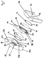
- FIG 3 shows an exploded assembly drawing of a preferred embodiment of the filter card 20 being connected to the water flowpath 50.
- the two enclosing members 40a, 40b are connected between the water flowpath 50 in order to enable a connection between the water flowpath 50 and the filter card 20.
- the two enclosing members 40a,40b enclose an aperture 42 formed by their surfaces 41a,41b into which the filter card 20 can be inserted.
- the semicircular ending 21a of the filter card 20 abuts on a semicircular recess 21b at the bottom of the aperture 42 enclosed by the two enclosing members 40a,40b.
- a linear groove 22a is preferably provided at one side of the aperture 42 and, preferably, one of the two enclosing members 40a,40b.
- the linear groove 22a is designed to receive the ridge 22 formed at one side of the filter card 20.
- the filter card 20 can only be inserted into the aperture formed by the two enclosing members 40a,40b in the correct side.
- Each of the two enclosing members 40a,40b comprises a circular recess 51 at its inside which is concentrically arranged and which is connected to the water flowpath 50.
- the diameter of the water flowpath 50 can be adapted to the diameter of the filter membrane 30 provided at the aperture 23 of the filter card 20. Accordingly, the whole surface of the filter membrane 30 provided at the filter card 20 can be used for filtering water.
- the recesses 51 are sealed by the sealing means 26 provided at the frame 21 of the filter card 20.
- the sealing means 26 may as well be provided on the enclosing member around the recesses 51.
- support members 25a are provided within the recesses 51 of the enclosing members 40a, 40b. These support members 25a are preferably cylindrical protruding ridges which are abutting on the support areas 25 provided at the perforated backing members 24, when the filter card 20 is inserted into the aperture 42 enclosed by the two enclosing members 40a,40b. Thus, deflection and/or breaking of the perforated backing members 24 and thus of the filter membrane 30 can effectively be prevented.
- the enclosing members 40a, 40b can be moved relatively to each other. Hence, after the filter card 20 is inserted into the aperture 42, the two enclosing members 40a, 40b can be approached and the position of the filter card 20 is fixed at a stable position and in a water-tight manner within the aperture 42. In the same manner, releasing the filter card 20 can be achieved by distancing the two enclosing members 40a, 40b from each other. In order to enable a relative movement of the enclosing members 40a, 40b, at least one of the enclosing members is connected to a closing mechanism (not shown) such as a lever or a motor which can be operated by a user.
- a closing mechanism such as a lever or a motor which can be operated by a user.
- the filter card 20 is disconnected from the device by distancing the enclosing members 40a, 40b from each other, the remaining water within the waterpath 50 and the circular recess 51 upstream of the filter is released in a controlled manner through an opening 51a provided at the bottom of the aperture 42.
- a collector below the opening 51a (not shown) is connected to a drip tray (not shown) so that the fluid can be discharged from the device.
- the aperture 23 of the filter card 20 comprises a circular support 28 for mounting the filter membrane 30 and the perforated backing members 24 thereon.
- the support 28 comprises locating means 29a,29b for determining the correct position of the filter membrane 30 and the backing members 24 when being mounted at the support 28 of the aperture 23.
- the locating means 29a provided at the support 28 interlock with locating means 30a provided at the filter membrane 30 and thus prevent relative rotation of the backing member and filter membrane and enable a user to correctly mount the filter membrane 30 at the support 28 of the filter card 20.
- the locating means 29a is at least one protruding ridge which fits in at least one correct recess 30a provided at the circumference of the filter membrane 30.
- the backing members 24 are preferably provided with recesses 24a which are equally distributed over the circumference of the backing members 24. Hence, these recesses 24a interlock with corresponding protruding ridges 29b which are disposed at the circumference of the support 28 of the filter card 20. Thereby, the locating means 29b,24a for the backing members 24 are designed such that the perforations of the backing members 24 on either side of the filter membrane 30 are aligned. Accordingly, a user can effectively be guided to mount the filter membrane 30 and the perforated backing members 24 at the filter card 20 in a correct way.
- two filter membranes 30 are mounted at the support 28 of the filter card 20 which are sandwiched between two perforated holders 24. It may as well be possible to mount three or more filter membranes 30 to influence the filtration properties of the filter card 20.
- a proximity sensor 54 may be provided at the bottom of the aperture 42 for inserting the filter card 20.
- the sensor enables to detect a presence of the filter card 20 within the aperture 42.
- the proximity sensor 54 is preferably connected to at least the pump 2 (see figure 1 ) of the device. Thereby, the sensor 54 preferably transmits a signal in response to the presence of the filter card 20 within the aperture 42. It can thus be ensured that the operation of the pump 2 is only possible when the filter card 20 is fully inserted into the aperture 42. Therefore, it can be prevented that a user unintendedly operates the device without having the filter card 20 fully inserted into the aperture 42.
- Figure 4 shows a preferred embodiment of the enclosing members 40a, 40b enclosing a filter card 20 when being inserted into the aperture 42 and thus being connected to the water flowpath 50.
- the filter membrane 30 is sandwiched between two perforated backing members 24. The perforations thereof are aligned such that water passed through the filter card 20 is not deflected.
- the water flowpath 50 is connected to a circular recess 51 formed in each of the enclosing members 40a,40b.
- protruding support members 25a are disposed, which are designed to abut on the support areas 25 of the perforated backing members 24 when the filter card 20 is inserted into the aperture 42. Thereby, the support areas 25 of the backing members 24 do not comprise any perforations.
- a circular recess 51b for housing sealing means is provided at both enclosing members 40a,40b.
- the circular recess 51b is preferably concentric to the circular recess 51 housing the protruding support members 25a.
- the circular recess 51b for housing the sealing means 26 is disposed radially outside of the circular recess 51.
- the sealing means 26 housed by the circular recess 51b enable an efficient sealing of the aperture 42 when the filter card 20 is provided within the aperture 42 and when water is passed through the filter card 20.
- the sealing means 26 is preferably an o-ring or the like.
- the sealing means 26 are preferably exchangeable. Hence, when the sealing means 26 are subjected to deterioration, a user may easily exchange the sealing means 26.
- the sealing means 26 may as well be provided at the frame 21 of the filter card 20.
- the two enclosing members 40a, 40b can be brought in tight contact to the filter card 20 by enable a relative movement of the two enclosing members, as already described.
- locking means 51a, 51b may be provided at the frame 21 of the filter card 20.
- the locking means are e.g. a snap fit.
- a protruding ridge 52a preferably provided at the frame 21 of the filter card 20, interacts with at least one corresponding recess provided at the snap fit member 52b.
- the snap fit member 52b is preferably an integral part of one of the enclosing members 40a,40b.
- the defined safe and stable position of the filter card 20 within the aperture 42 is ensured by frictional forces (press fitting) between the frame 21 of the filter card 20 and the adjacent faces 42a, 42b.
- the fit of the frame 21 within the aperture 42 is chosen such that a user has to apply a certain force onto the filter card 20 in order to fully insert the filter card 20 into the aperture 42. The same applies for removing the filter card 20 from the aperture 42.
- Fig 5a and 5b show a preferred embodiment of a backing member 24.
- the backing member 24 has individual arcuated recesses 53a and ridges 53b which are formed to enable a perfect fit of two equal backing members 24 in a predefined angular position.
- the recesses 53a and ridges 53b of the first backing member 24 interlock with provided ridges 53b and recesses 53a of the second backing member 24.
- a relative rotation of the backing members 24 can be prevented.
- the relative angular position of the two backing members 24 is defined by the recesses 53a and ridges 53b, the perforation of the two backing members 24 can be effectively aligned.
- support areas 25 are provided at the backing member 24 in order to provide a surface onto which the support members 25a (see figure 3 ) of the device can abut.
- the recesses and ridges are preferably arranged symmetrically about the perpendicular axes A1 and A2. Moreover, a semicircular recess 53c and a protruding semicircular part 53d are formed at opposing endings of the backing member 24. Hence, when two equal backing members 24 are connected to each other, the semicircular recess 53c and protrusion 53d of the two backing members 24 interlock with each other and the correct predefined assembly position of the two backing members 24 is obtained.
- a filter membrane 30 (not shown) is placed which preferably has an outer diameter which is bigger than the diameter of the portion of the backing member 24 which is perforated.
- the protruding recesses 53a and ridges 53b may vary in their dimensions.
- the height of the recesses 53a and ridges 53b may be adjusted to enable a correct fitting of the two backing members 24 when assembled.
- the recesses and ridges may overlap as indicated by reference B in figure 5a . Thus, a tight and correct fitting of the two backing members can be obtained.
- the filter membrane 30 is placed on one of the backing members 24. Then, the second backing member 24 is placed onto the first backing member 24, wherein their relative position to each other is defined by the arcuated recesses 53a and ridges 53b provided on their joint face.
- the frame 21 is injected. Thereby, injection ports are preferably provided at the backing members 24 in order to enable plastic material to pass through during the injection process and hence further secure the membrane between the backing members 24.
- sealing means 26 which may be provided at outer surfaces of the backing members 24 can be placed in provided recesses at the backing members 24 before the injection process. Accordingly, the sealing means 26 can be secured to the backing members 24 by the injection process as well.
- Figure 6 shows a sectional drawing of a preferred embodiment of a filter card 20.
- the filter membrane 30 is sandwiched between two perforated backing members 24.
- the perforation of the backing members 24 is designed such that the diameter of the perforations widens towards the filter membrane 30, i.e. the diameter of the perforations is bigger at the surface adjacent to the filter membrane 30 than at the outer surface of the backing member 24 being directed towards the water flowpath 50 (see figure 4 ).
- the two backing members 24 are interlocking due to provided circular recesses 53a and ridges 53b on the backing members 24.
- the position of the ridges 53b is chosen such that the filter membrane 30 is as close as possible to the protruding inner edge 53c of the protruding ridges 53b and/or recesses 53a.
- the filter membrane 30 can efficiently be held in place and a tight enclosing of the filter membrane is obtained.
- a lip-seal 26 is provided to the outer surfaces of the backing members 24 in order to seal the filter assembly when the filter card 20 is in connection with the water flowpath 50.
- the sealing means 26 and the backing members 24 can be effectively connected to the frame 21 of the filter card 20 by means of the injection process during manufacturing of the frame 21.
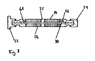
- FIG. 7 is a sectional side view of another preferred embodiment of a filter card 20.
- an o-ring 56 is placed in a provided circular recess 61 at one of the backing members 24. Accordingly, the outer joint face between the filter membrane 30 and the backing members 24 is sealed and water cannot by-pass the filter membrane 30.
- the recess 61 and hence the o-ring 56 is provided at the backing member 24 which is situated on the upstream side of the filter card 20.
- plastic material may be provided to the outer edge of the filter membrane 30 such that the plastic material is compressed by the backing members 24 when the filter card 20 is assembled.
- plastic material can e.g. be applied to the filter membrane(s) by means of rubber overmolding. Accordingly, effective sealing of the filter membrane 30 can be provided such that water passed through the filter card 20 is prevented from by-passing the filter membrane 30 through the joint face of the two backing members 24.
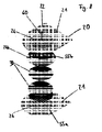
- Figure 8 shows an exploded assembly drawing of another preferred embodiment of the filter card.
- the backing means 24 are an integral part of the frame 21 of the filter card 20.
- the backing means 24 are relatively large compared to the other embodiments.
- the backing means 24 may be grids formed in the frame 21.
- dedicated support members 25a see figure 4
- the device can abut on the grid 24 in order to support a stable position of the filter card 20 when it is inserted into the aperture 42 (see figure 4 ) of the device.
- the frame 21 comprises two parts which can be assembled in order to enclose a filter membrane 30 there between.
- locating means 55a are provided.
- the locating means 55a are protruding and/or recessed bolts arranged circularly around the grids 24.
- At least one filter membrane 30 is sandwiched between the grids 24 and thus can be effectively supported when water is passed trough the filter membrane 30.
- the direction of the preferred water flow through the assembly is indicated by arrow 60.
- two or more filter membranes 30 are situated between the grids 24.
- the filter membranes 30 are of different pore sizes.
- the filter membrane situated relatively upstream has a wider pore size than the filter membrane(s) situated relatively downstream.
- the upstream filter membrane has a nominal pore size of 0.65 ⁇ m and the downstream filter membrane has a nominal pore size of 0.22 ⁇ m.
- an additional membrane support 24b may be provided between the grids 24 in order to further support the filter membrane(s) 30.
- the support member 24b is a circular aluminium grid wherein the openings of the grid have a smaller size than the backing members 24 of the frame 21. More preferably, the additional support 24b is positioned downstream of the filter membrane(s) 30.
- locating means 55b are preferably provided at the membrane support 24b which interact with the locating means 55a provided at the frame 21 in order to hold the support 24b at a fixed position relative to the frame 21.
- the locating means are apertures formed close to the outer edge of the circular support member 24b.
- the two frame parts 21 can be manufactured e.g. injected as separate pieces.
- the additional backing member 24b may be fixed, e.g. glued, onto one of the backing members 24.
- two backing members 24b may be provided at each side of the filter membrane(s) 30.
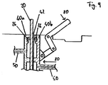
- Figure 9 shows a preferred embodiment of the closing mechanism 70 of the device which is provided in order to enclose the filter card 20 between the two enclosing members 40a, 40b.
- the closing mechanism is preferably a lever connected to at least one of the enclosing members 40a, 40b which are moveable relative to each other.
- a dedicated motor which may be operated by a push button can be provided in order to enable a relative movement of the two enclosing members 40a, 40b.
- the two enclosing members 40a, 40b are arranged such that a dedicated aperture 42 for inserting the filter card 20 is formed between them.
- the user may operate the closing mechanism 70 in order to enclose the filter card 20.
- the closing mechanism 70 transmits mechanical forces in order to move the enclosing member 40b towards the other enclosing member 40a, as indicated by arrows 80.
- the two enclosing members 40a, 40b are approached and the filter card 20 situated between them is fixed in its position. Accordingly, the filter card 20 can be secured at a stable position in the aperture 42.
- the sealing means 26 provided at the enclosing members 40a, 40b are pressed against the surface of the filter card 20, thereby enabling a water-tight sealing of the assembly.
- the closing mechanism is to be operated in advance in order to separate the two enclosing members 40a, 40b.
- the filter membrane may be provided in another embodiment of a filter frame means such that the filter membrane can be exchanged relatively easy by any operator of the device. It may as well be possible to mount more than two filter membranes at the filter card in order to enhance the filtration properties of the filter card. Moreover, other filtration media could be incorporated by the removable filter card which enables a sufficient filtration of water.
- a filter card having two or more apertures, each of them housing at least one filter membrane and at least one backing member, in order to filter water passed through two or more water flowpaths of a device to which the filter card is connected.
- different embodiments of locating devices for the filter membrane and the backing members may be provided at the frame means of the filter card in order to enable the correct mounting of the filter membrane and the backing members.
Landscapes
- Engineering & Computer Science (AREA)
- Food Science & Technology (AREA)
- Separation Using Semi-Permeable Membranes (AREA)
- Apparatus For Making Beverages (AREA)
- Non-Alcoholic Beverages (AREA)
- Apparatus For Disinfection Or Sterilisation (AREA)
Abstract
The present invention proposes a device for preparing a nutritional composition by supplying water to ingredients provided to the device comprising a pump (2) being connected to an integrated or external water supply(1), a water discharge head (4) designed for providing water to a cartridge containing ingredients (7) for interaction between water and the ingredients in the cartridge (7), wherein the pump (2) and the water discharge head (74) are in water communication via a water flowpath (50), whereby the pump can supply water under pressure through the water flowpath, a rigid filter assembly (20) comprising at least one antimicrobial filter membrane (30) and filter enclosing means (40a, 40b), wherein the filter assembly (20) and the filter enclosing means (40a, 40b) are complementary configured such that the filter assembly (20) is insertable into the filter enclosing means (40a, 40b) across the water flowpath (50) in a fluidtight manner before the water discharge head (4), and is removable from the filter enclosing means (40a, 40b).
Description
- The present invention relates to a filter for a device for providing a ready-to-drink nutritional composition such as an infant formula. More particularly, the present invention relates to an exchangeable filter card which is removably insertable into a device in order to improve the hygiene level and ease the maintenance of the device.
- Infant formulas have been developed as a substitute for human breast milk in order to provide required nutrients to infants. In general the infant formulas are either based on cow or soy milk and may be provided in different forms such as powder or concentrated liquid form.
- Each of the different forms in which infant formulas may be provided has their own advantages. For instance, although the infant formula provided in a powder form has a relative high nutritional quality, the preparation thereof may be regarded as inconvenient and time consuming, since water which has been boiled in advanced and allowed to cool has to be poured into a sterilised drinking vessel containing the powder in order to prepare a liquid infant formula. The same inconvenient preparation process exists for infant formulas in concentrated liquid form.
- If prepared and consumed in this manner, powdered infant formulas provide a safe and nutritionally good substitute for mother's milk. However, primarily due to the inconvenient preparation, many parents or caregivers do not prepare the formulas properly and hence expose the infant to risks of infection or other risks. For instance, if water is not properly sterilized prior to use or if the final preparation is prepared too long in advance, there can be a risk of transmitting pathogens to the infant. Usually, water sources in developed countries are safe but this may not be the case everywhere.
- In further development, infant formulas in ready-to-feed single serve portions have been introduced which overcome the inconvenience of the preparation of the infant formula. However, these ready-to-feed products are more costly than infant formulas stored in bulk and they often suffer the disadvantage that once the portion is opened, it has to be consumed immediately to avoid the risk of contamination with bacteria. Moreover, even the single serve portion infant formulas are reconstituted with water. Hence, there is a risk that the water may not necessarily be properly sanitized and that the single serve baby bottles are prepared in advance in bulk and stored.
- The immune defences of infants and young children are generally not fully developed and, as a result, these populations are particularly vulnerable to both bacterial and viral infections. For example, they may be prone to infections in circumstances where the immune system of a healthy adult would resist infection or they may suffer more serious consequences as a result of infection than would a healthy adult. Similar difficulties may arise in populations where the immune system is compromised such as the elderly. The consequence of this is that devices that prepare nutritional compositions which are perfectly safe for healthy adults may not be able to produce products which meet the increased safety standards required for products to be consumed by subjects having immature or compromised immune systems.
- Therefore, a method or an apparatus is sought-after which enables a provision of nutritional composition for instance an infant formula in a convenient and safe manner.
-
WO2006/077259 discloses a method for preparing a single serving of a nutritional composition comprising introducing liquid such as water into a cartridge containing a unit dose of the composition in concentrated form. Thereby, the water is treated prior to the introduction into the cartridge in order to remove pathogens from the water. This treatment may be for instance a pre-heating, a filtering or an irradiation of the water with ultra-violet light. - A device which teaches the principle of treating water by means of a filter used for the preparation of nutritional compositions in a dispenser from cartridges is disclosed in co-pending European patent application No.
06117801.8 filed 25 July 2006 - In order to ensure a high standard of safety with regard to the removal of any pathogens which may be contained in a liquid used for the preparation of a nutritional composition, the provided filter of such a device may have to be changed repeatedly. Therefore, an improved filter system is sought-after which enables exchangeability and/or maintenance of the filter to provide the necessary level of hygiene and food safety.
-
US20070199888 relates to a water filter for a coffee machine that has tabs to be attached to the brew basket of a machine. However, this water filter is simply slidably engaged below a brewing basket which receives water at atmospheric pressure. The filter is said to have a thickness of several millimetres. However, this filter is not intended to remove pathogens to treat water. - The present invention seeks to address the above described problems. The invention also aims at other objects and particularly the solution of other problems as will appear in the rest of the present description.
- In a first aspect, the present invention proposes a device for preparing a nutritional composition by supplying water to ingredients provided to the device,
- said device comprising a device for putting the fluid under pressure, e.g. a pump, being connected to an integrated or external water supply,
- a water discharge head for providing water to a cartridge containing ingredients for interaction between water and the ingredients in the cartridge, wherein the pump and the water discharge head are in water communication via a water flowpath, whereby the pump can supply water under pressure through the water flowpath,
- a rigid filter assembly comprising at least one antimicrobial filter membrane and filter enclosing means, wherein the filter assembly and the filter enclosing means are complementary configured such that the filter assembly is insertable into the filter enclosing means across the water flowpath in a fluidtight manner before the water discharge head, and is removable from the filter enclosing means.
- With a device according to the present invention, it is possible to enable an interaction between water supplied in the device, more particularly by the pump connected to the water supply, and ingredients contained in the cartridge. Thereby, water is preferably provided to the water discharge head by a water supply disposed upstream, e.g., at an upper side, of a cartridge receiving chamber. Note that the term "water supply" encompasses also any water supply line of the device which is connectable to an outside tap water or reserve of water foreign to the device itself.
- The water in the disclosed invention is inserted in the cartridge through a needle with a preferred flow rate of approximately 400 ml/min. This creates a jet with sufficient energy to dissolve the ingredients within the cartridge. The filter membrane of the antimicrobial filter may be chosen dependent on the pressure drop across the membrane within the water flowpath. The lower the pressure drop across the filter, the higher the energy of the jet and therefore the dissolution of the ingredients within the cartridge.
- An outlet is preferably disposed downstream, e.g., at a lower side of the water discharge head. Thus, after the interaction between the water and ingredients in the cartridge, the output of the nutritional composition to be prepared takes place downstream, e.g., at the lower side of the water discharge head thence, enabling a flow of the nutritional liquid composition into a receptacle such as a cup or a vessel which may be placed beneath the cartridge.
- In another preferred embodiment, it may as well be possible to place the filter means downstream of the water discharge head. Hence, the filter may be used for filtering the dissolved infant formula which results from introducing water into the cartridge. Accordingly, any pathogens in the infant formula can be removed. As the resulting liquid flow discharged by the cartridge is not subjected to high pressure, means for enabling a predefined flow rate through the filter may be provided. For example, the surface of the filter may be enlarged or pressure may be exerted on the resulting liquid flow from the cartridge by means of a dedicated pump or the like.
- The rigid filter assembly provided to the water flowpath between the pump and the water discharge head is provided with at least one antimicrobial filter membrane acting as a physical barrier to control the permeability to microorganisms, in particular, block the passage to bacteria or pathogens potentially present in the supplied water. Hence, a safe preparation of the nutritional composition can be assured.
- In a preferred embodiment, a cartridge containing ingredients for the preparation of a nutritional composition may be provided. The cartridge is received in a cartridge receiving chamber of the device. Said cartridge is preferably a single-use cartridge which contains a dose of nutritional composition to be hydrated (e.g. diluted, dispersed and/or infused with water). Thus, water provided to the cartridge can be used to reconstitute the nutritional composition. The cartridge preferably comprises a water injection face and a delivery face.
- In possible modes of "direct-flow" gastight cartridges, preferably, as described in European patent
EP1472156B1 , or also eventually in other modes such as in international patent applicationWO2007131559 , a pressure is typically built up within the cartridge during water injection, which causes a lower face (or septum) of the cartridge to open thence, enabling the output of the liquid to be prepared. Since the output of the beverage to be prepared takes place at the lower face of the cartridge with no contact with opening means of the device, the flow of the liquid can be directly poured into the receptacle, e.g. a baby bottle, without contaminating the surfaces of the device. This results in a very hygienic preparation and delivery of the nutritional preparation. - After the injection of water into the cartridge, the pouring from the cartridge may be delayed in order to provide sufficient time for interaction of the water and the ingredients, e.g., to obtain complete dissolution of the ingredient in water. For the pouring of the beverage to be prepared from the cartridge, opening means such as reliefs which may be arranged against a delivery tearable foil in order to tear the membrane in a controlled manner. These opening means interact with the foil in response to the pressure rise within the cartridge when injecting water. The nutritional composition to be prepared can then flow directly from a dedicated outlet of the cartridge into the receptacle without contacting the device.
-
EP1472156B1 discloses various suitable cartridge configurations that may be used in the device of the present invention. - Thereby, the use of a new single-use cartridge for the preparation of a nutritional serving coupled with the specific "direct flow" features of the cartridge, i.e., including an inside pressure-responsive opening technology within the cartridge and draining the liquid directly from the cartridge into a receiving vessel such as an infant's bottle both greatly facilitates the preparation of the nutritional product and make it significantly safer with substantially reduced or even eliminated risk of contamination.
- This is particularly advantageous if the apparatus is to be used in a hospital nursery where infant formulas must be prepared not only for healthy infants but also for infants suffering from specific diseases, deficiencies or severe allergies, for example allergies to cows' milk.
- Moreover, the device may be provided with means to regulate the amount and/or temperature of water to be dispensed into the cartridge so that it stops the flow of water when a preselected or automatically controlled quantity has been dispensed. Water regulation means may comprise a water pump, and a control unit of the device comprising programs, a cartridge recognition system between the cartridge and device, e.g., barcodes on the cartridges and the like, for properly controlling the physical conditions of water delivered in respect to the type of cartridge.
- The device may further be provided with purging means to empty the cartridge from residual liquid, for example, by flushing the liquid in the cartridge with a gas. Purge means also reduce the risk of contamination by a back-flow of the nutritional composition into the device. A suitable gas is compressed air at a pressure of between 200 mbar and 2 bar, for example 300 mbar which can be pressurized by an air compressor in the device.
- Since the filter assembly is designed to be inserted to or removed from the device, a used filter assembly can be exchanged by a new filter according to user's instructions or in response, for example, to an alerting signal, such as a led flashing on the device or an indication on an LCD screen. These indications can be triggered when a specific number of servings have been provided or when a specific volume of water has been run through the filter assembly. The change signal may as well be triggered by a sensor measuring the flow rate through the filter or the pressure above and/or below the filter. Alternatively, the filter assembly can be recycled, for example, by carrying out a proper thermal processing of the filter assembly out of the dispenser, e.g., sterilization, according to user's instructions. Thus, the filter means can be removed effortlessly after a certain pre-defined time for exchange or recycling in order to ensure proper water filtering conditions in the device ensuring a safe water supply to the device. However, the filter may as well be sterilized within the machine by a provided steam generator.
- Preferably, the filter assembly connected to the device comprise a frame for housing at least one antimicrobial filter membrane. Thereby, the antimicrobial filter membrane means a filter that is designed to filter pathogens or undesired micro-organisms such as bacteria, virus, yeast and/or molds or other microparticles, from water to be filtered. The antimicrobial filter membrane may have a nominal pore size of 0.45 microns or less. A particularly preferred nominal pore size is between 0.01 and 0.45 microns. For filtering bacteria, the nominal pore size can be of between 0.1 to 0.3 microns, most preferably of about 0.2 microns. For filtering virus, the pore size can be reduced as low as 0.05 microns or even lower. A more porous membrane could be selected if a higher flow rate is required when the removable of pathogens is less critical. For the use with the present device, a superposed hydrophilic PES (polyethersulphone) membrane produced by Pall Corporation Switzerland or any other thin filter membrane e.g. made from a polymer having comparable specifications can be used (e.g. Millipore membranes). Antimicrobial filter membranes made from plastic materials are preferred. Preferably the thickness is less than 2 µm, more preferred less than 1 µm. Preferably the filter assembly comprises one or more of these thin membranes. Preferably the anti-microbial effect is achieved by filtration and not e.g. by adsorption produced e.g. by activated carbon. This has the effect that the filter can be more easily regenerated (in comparison to activated carbon).
- By use of such a filter, the risk of contamination of the nutritional composition to be prepared can be significantly minimized.
- The thin antimicrobial filter membrane(s) being physically sensitive and not easy to manipulate, the filter assembly preferably comprises water permeable backing means positioned, preferably adjacent, to support the antimicrobial filter membrane(s). Such backing means may for example be a perforated wall, ridges or the like which are abutting on the filter membrane in order to support at least partially the surface of the filter membrane. Thus, breaking and/or deflection of the filter assembly when water is passed through it can effectively be prevented.
- Moreover, in case the filter is blocked, the differential pressure across the filter membrane can go from about 0.1 bar up to 10 bars. In such a case, the backing means can provide a protection for the filter membrane in order to prevent rupture of the membrane. The backing means also provide a protection for the membrane when it is manipulated and inserted in the device.
- In order to ensure fluid tightness between the filter assembly and the water path of the device, sealing means are provided at the interface of the filter assembly and device. Preferably, the sealing means are located around the filtering section of the filter assembly and/or the outlet and inlet of the channels. The sealing means may be part of the water communication channels of the dispensing device and/or part of the filter assembly. A possible material for the seal is Santopren or Thermolast K. Preferably, a lip-seal is provided which enables a water-tight assembly of the filter and the device at high pressures.
- The device further comprises a steam generator connected to the fluid communication path in order to sanitize the filter assembly and the other surfaces of contact with water such as the tubings, the water discharge head and the cartridge receiving chamber of the device. The filter is therefore manufactured and assembled in such a manner to resist steaming, up to, for example, 120 °C. Therefore, according material is selected, e.g. PP for the rigid frame of the filter assembly and Santopren for the seal.
- The filter assembly for the device can be preferably inserted to or removed from an aperture disposed in an easy accessible position. The aperture is preferably disposed on one face of the device, e.g., the top face of the device. Thus, the exchangeability of the filter assembly is significantly enhanced since any user may carry out an exchange of the filter assembly.
- Multiple use of the same filter membrane should be prevented as the filter does not have the same properties after being used during a long time. Therefore, an element may be mounted on the filter assembly and/or on the device to prevent multiple use of the same filter membrane. Each filter membrane may for instance be individually marked with a barcode and remembered by the device. Another possible solution is to have an element on the filter assembly that breaks when the filter is removed and prevents a new insertion mechanically or by a sensor in the device.
- When the filter assembly is fully inserted to a corresponding aperture of the device, the filter assembly may be locked by locking means provided at the filter assembly and/or the device. For example, a snap fit may be provided at the filter assembly which may interact with a protruding or recessed element provided in vicinity of the aperture of the device when the filter assembly is fully inserted into the aperture. When a user intends to remove the filter assembly from the device, the snap fit can be released by the user and hence, the filter assembly can be removed from the aperture of the device. The filter assembly may as well be locked within the aperture by means of friction which is exerted onto the filter assembly by the adjacent faces at the inside of the aperture when the filter assembly is connected to the device. Frictional forces may as well be exerted by the sealing means of the filter assembly and the corresponding faces within the aperture being adjacent to the sealing means when the filter is inserted into the aperture. When inserting the filter assembly into the aperture, the user has to apply a certain force in order to overcome the frictional forces and hence fully insert the filter assembly into the aperture. The same applies to the removal of the filter assembly from the aperture. Accordingly, locking of the filter card within the device is achieved and the filter assembly can be connected to the device in a stable and safe manner.
- In another preferred embodiment, the closing mechanism comprises at least two enclosing members to enclose the filter assembly which are relatively moveable to each other. Accordingly, when the filter is provided to the corresponding aperture at the device, the closing mechanism is to be operated by a user in order to enable a relative motion of the enclosing members and hence enclose the filter assembly situated within the aperture. Thus, as the enclosing members are approached, a filter assembly situated between the enclosing members can be effectively enclosed. Accordingly, the filter assembly can be hold at a fixed and stable position during operation of the device. For this purpose, a lever may be provided at the housing of the device which is connected to at least one of the enclosing members. Thus, by operation of the lever, a user may enclose and/or release the filter assembly between the enclosing members. Of course, the enclosing of the filter assembly may be operated automatically. Therefore, a button may be provided at the housing of the device which enables an operation of a dedicated motor which permits a relative motion of at least one enclosing member to enclose and/or release the filter assembly within the aperture.
- In addition, a proximity sensor may be provided at the bottom of the aperture in order to detect a presence of the filter assembly. Thereby, the proximity sensor is connected to the pump of the device. Thus, the operation of the pump is preferably only possible when the proximity sensor detects a presence of the filter assembly. Accordingly, a safe operation of the system is enabled as the device can only be operated when the filter assembly is fully inserted into the aperture of the device.
- The nutritional composition to be prepared by the device according to the present invention may be any composition which by nature is very sensitive to contamination by pathogens. Examples of preferred nutritional compositions for use in the method of the present invention are infant formulas, growing up milks and liquid infant cereals. The ingredients of the composition are not critical to the method of the present invention and other food powder or liquid concentrate may be used. Examples of different types of infant formula that may be used in the method of the present invention include whey protein dominant formulas, formulas containing a mixture of whey and casein, formulas based on other proteins such as soy, formulas in which the protein component is partially or extensively hydrolyzed etc. The nutritional composition is preferably stored in a gastight single-use cartridge provided to the chamber, in powder form or concentrated liquid form.
- A ready-to-drink nutritional composition may also be prepared according to the method of the present invention using more than one cartridge to prepare a single serving. This permits a degree of flexibility in the compositions that is prepared. For example, a range of cartridges containing different supplements may be manufactured and consumers may be provided with instructions as to how to combine these to prepare a personalized composition suited to the particular needs of the recipient.
- In a second aspect, the invention proposes a filter card for being connected to a device for preparing a nutritional composition, said filter card comprising a frame for holding in position at least one antimicrobial filter membrane and at least one rigid water permeable backing member for supporting the filter membrane. The backing member may be placed adjacent or close to the filter membrane. The backing member may be perforated with small holes but of a diameter sufficiently large to minimize the pressure drop at the member.
- With a filter card according to the present invention, the required water filtering function for the device can be provided in a more convenient and safer way. In particular, the exchange of the filter means by a filter card can be operated by any user. Moreover, the rigidity of the frame of the card makes it easy to manipulate and to protect the fragile and not inherently form stable membrane(s), as well as to ensures the correct positioning of the card in the device.
- Moreover, the perforated backing member(s) disposed adjacent to the antimicrobial filter membrane(s) supports the filter membrane to maintain its integrity under the pressure of water (e.g., avoid it to tear, collapse, deflect or crease). Thereby, the perforations have preferably a wider diameter than the pores of the filter membrane (e.g. 0.6 mm). Hence, water passing through the filter card is not deflected by the backing members and the filter membrane can be subjected to a high liquid flow rate without the risk of deflection and/or breaking of the filter membrane.
- Preferably, the frame of the filter card is made of rigid plastic and/or metal material.
- The filter membrane is a preferably flat membrane which has a nominal pore size between 0.01 and 0.45 microns, most preferably between 0.1 and 0.3 microns, as already described. Hence, pathogens present in the water to be used for the preparation of the nutritional composition can effectively be blocked in the membrane. It can be noted that the membrane is asymmetrically designed in such a manner that it may comprise a varying pore section in the flow direction through the membrane thus determining an inlet filtering side and an outlet filtering side for the membrane. In particular, the pore widens from inlet side toward the outlet side.
- In another preferred embodiment, at least one antimicrobial filter membrane is sandwiched between at least two perforated backing members. Thereby, the perforations of the backing members can be aligned such that water which is conducted through the perforations is not deflected. Moreover, the perforations have preferably a wider diameter than the pores of the filter membrane. Hence, water passing through the filter card is not deflected by the backing members. Thereby, the flow resistance generated by the perforations of the backing members can be regarded as lower than the flow resistance of the pores of the membrane(s).
- However, it may as well be possible to provide an embodiment of the filter card, wherein two or more perforated backing members of aligned perforations are situated at each side of the filter membrane. The upstream backing member thereof which are disposed adjacent to a first filter membrane have preferably perforations of smaller diameter than a downstream backing members. Therefore, the outer backing members are designed such that no water is deflected when being passed through the filter card. The downstream backing member may support a second filter membrane. Accordingly, it is possible to provide a filter card which can sustain a high pressure drop across the filter card when being connected to a water flowpath. Preferably, the pressure drop within the water flowpath across the filter means is below 1 bar.
- Furthermore, the filter card preferably comprises sealing means for ensuring water tightness of the filter when being connected to the device, in particular, for avoiding any water to by-pass the filter card. Hence, when water is passed through the filter card, the sealing means prevent a leakage of the water flowpaths into which the filter card is inserted.
- Moreover, the perforated backing members of the filter card may be designed such that they can be supported by support members of the device to which the filter card is connected. For instance, support areas may be provided at the surface of the backing members. Thus, support members connected to the device may be designed to abut on said support areas in order to provide additional support for the filter card against deflection and/or breaking. Hence, a stable and fixed position of the filter card within the water flowpath can be assured.
- Preferably, the filter card further comprises guiding means which are connected to the frame of the filter card. The guiding means can be asymmetrical such that the filter card is insertable in the device by only one predetermined side. The guiding means may be a protrusion or, alternatively a groove, at only one side of the frame which fits in a corresponding groove or, alternatively protrusion, in the aperture of the device into which the filter card may be inserted. This asymmetrical card configuration ensures that the user is effectively prevented from inserting the filter card in the wrong way. Since as described, the filter membrane(s) may be designed asymmetrically, it is important to respect a correct insertion side of the card.
- Furthermore, the filter card may be equipped with locking means in order to ensure a safe and stable connection between the filter card and the device the filter card is connected to. For example, a snap fit may be provided at the filter card which may interact with a protruding or recessed element provided in vicinity of an aperture at the device when the filter card is fully inserted into the aperture. Thus, when a user intends to remove the filter card from the device, the snap fit can be released by the user and hence, the filter assembly can be removed from the aperture of the device.
- Moreover, it is important to ensure that the water to be filtered is flowing through the filter membrane(s) and will not bypass it by its outer edge. Therefore, sealing means are provided between the backing means and the filter membrane. Such sealing means may comprise plastic sealing material which is provided to the outer edge of the filter membrane by an overmolding process. Alternatively, an o-ring may be provided within the assembly to prevent the water from by-passing the filter membrane. In case an o-ring is used, the filter membrane should be monodirectional in order to prevent a radial water flow trough the membrane and bi-pass it by capillarity.
- Further features, advantages and objects of the present invention will become apparent for the skilled person when reading the following detailed description of embodiments of the present invention, when taking in conjunction with the figures of the enclosed drawings.
-
Fig. 1 shows a schematic drawing of a preferred embodiment of the device according to the present invention for preparing the nutritional composition. -
Fig. 2 shows a perspective view of a preferred embodiment of the filter card according to the present invention. -
Fig. 3 shows an exploded assembly drawing of a preferred embodiment of the filter card being connected to the water flowpath. -
Fig. 4 shows a sectional drawing of a preferred embodiment of the filter card being connected to the water flowpath. -
Fig. 5a shows a preferred embodiment of a backing member in top view. -
Fig. 5b shows a sectional drawing of a preferred embodiment of a backing member according to line A-A shown infigure 5a . -
Fig. 6 shows a sectional drawing of a preferred embodiment of the filter card being equipped with a filter membrane sandwiched between two backing members. -
Fig. 7 shows a sectional drawing of another preferred embodiment of the filter card being equipped with an o-ring. -
Fig. 8 shows an exploded assembly of another preferred embodiment of the filter card wherein the backing members are formed as an integral part of the filter card frame. -
Fig. 9 shows a preferred embodiment of an enclosing mechanism designed to secure the position of the filter card within the dedicated aperture of the device. -
Figure 1 shows a schematic drawing of a preferred embodiment of a device according to the present invention. The device comprises a water supply 1 connected to awater pump 2. The output of the pump is connected to aheater 3 which preferably comprises a coiled stainless-steel pipe in a die cast aluminium thermoblock (not shown). Power is supplied to the thermoblock sufficient to heat the water to the desired temperature as it passes though the pipe. The output of the heater is connected to afilter 5 which is connected to the discharge or injection head 4 of the device. Said discharge head 4 comprises a chamber 9 for housing a cartridge 7. The term "cartridge" refers, in the general concept of the invention, to a single-use package such as pod, capsule or sachet of various packaging materials containing nutritional ingredients. - The term "pump" means any technical means that can transport a liquid at a sufficient positive pressure from the water supply to the injection head. This means can be a pressure pump such as a piston pump, a diaphragm pump, a peristaltic pump, a gear pump, a centrifugal pump, a progressive cavity pump, a hand pump and the like.
- Furthermore, flow control means 2a are provided preferably between the
pump 2 and theheater 3 of the device. Moreover, temperature control means 3a are provided preferably between theheater 3 and the discharge head 4. Hence, the temperature and the flow of a liquid within the device can be controlled and adjusted. - In addition, an
air pump 6 is connected to discharge head 4 in order to enable the flushing of any residua within a cartridge 7 into a receptacle disposed beneath the cartridge 7. - The cartridge 7 which is shown only schematically contains approximately 10ml of ingredients. The ingredients are preferably provided in a powdered or in a liquid concentrated form within the cartridge 7. The preparation of a 100-ml single serving of a nutritional beverage such as infant formula with the device according to the present invention will now be described.
- The cartridge 7 is located in the cartridge receiving chamber 9 of the discharge head 4 such that an injection element (not shown) protruding into the chamber 9 punctures a membrane sealing the cartridge 7. Flow control means 2a and temperature control means 3a are set such that a desired quantity of water at the desired temperature is provided to the cartridge. Thereby, water is preferably pumped at a pressure of about 0.2 bar from a water tank 1 (or a water supply line from outside) to the
heater 3 where it is heated to a preferred temperature between 25 and 40°C. The heated water is then passed through thefilter 5 to the chamber 9 of the discharge head 4 at a preferred pressure between 2 and 7 bar and dispensed from there into a cartridge 7 which contains a unit dose of a nutritional composition such as an infant formula. When the pressure in cartridge 7 reaches a predetermined value which is preferably 2,5 bars, the cartridge opens and the reconstituted infant formula is dispensed directly from the cartridge into a suitable receptacle such as a baby bottle (not shown). Theair pump 6 is then operated to flush any remaining liquid out of the cartridge and into the receptacle. - In addition, a steam generator 8 is connected to the discharge head 4 and to the
filter 5. In operation, the chamber 9 of the discharge head 4 and thefilter 5 may be sterilised as often as desired by passing steam from the steam generator through the discharge head 4 and thefilter 5. -
Figure 2 shows a preferred embodiment of afilter card 20 according to the present invention. Thefilter card 20 comprises aframe 21 designed for housing a filter membrane 30 (shown infigure 3 ) and at least one rigidperforated backing member 24. Theframe 21 are preferably of rigid plastic or metal material equipped with asemicircular ending 21a which is the ending to be first introduced into an aperture such as a slot provided at a device and designed to receive thefilter card 20. Due to thesemicircular ending 21a, thefilter card 20 can easily be inserted into a provided slot of the device, even if a user inserts thefilter card 20 in a slanted way or offset the central axis of the aperture. - Furthermore, the
filter card 20 comprises guiding means 22 in order to prevent a user from inserting thefilter card 20 into a provided slot in an incorrect side. Preferably, the guiding means 22 is at least one protruding ridge provided at one of the edges of thefilter card 20 and designed to be received by a corresponding groove 22a (shown infigure 3 ) provided at the aperture of the device, thefilter card 20 is designed to be inserted to. Preferably, the guiding means 22 are an integral part of theframe 21. - As shown in
figure 3 , theframe 21 comprise a preferablycircular aperture 23 for housing thefilter membrane 30 and at least oneperforated backing member 24. More preferably, at least onefilter membrane 30 is placed or sandwiched between at least two backingmembers 24 which are situated in parallel and in close contact to thefilter membrane 30. Furthermore, thebacking members 24 are perforated in order to enable a flow of fluid through thefilter membrane 30 and thus through thefilter card 20. The diameter of the perforations of thebacking members 24 is preferably wider than the nominal pore size of the providedfilter membrane 30. Thus, the flow resistance of thebacking members 24 does not influence the overall flow resistance of thefilter card 20 in a negative way. Moreover, in the case when two or moreperforated backing members 24 are provided to thefilter card 20, the arrangement of thebacking members 24 is adjusted such that the perforations of thebacking members 24 are aligned. Hence, water which is passed through thefilter card 20 is not deflected. - The
backing members 24 are preferably designed to be supported bysupport members 25a (shown infigure 3 ) of the device to which thefilter card 20 is intended to be connected. Saidsupport members 25a may for instance be ridges or the like designed to abut on thebacking members 24 when thefilter card 20 is connected to the device. Therefore, the surface of thebacking members 24 comprisessupport areas 25 onto which thesupport members 25a may abut. Thesupport areas 25 are preferably uniformly distributed over the surface of the backingmember 24. Thesupport areas 25 do not comprise any perforations such that thesupport members 25a abutting on thesupport areas 25 do not deflect any water passed through the perforations of thebacking members 24. Accordingly, thesupport areas 25 of thebacking members 24 abutting on givensupport members 25a enable a stable position of thefilter card 20 when being connected to a device for preparing a nutritional composition. The risk of deflection or breaking of thefilter card 20 or particularly of thefilter membrane 30 when water at high pressure is passed through the perforations of thebacking members 24 can thus effectively be minimized. - Furthermore, the protection of the
filter membrane 30 against deflection or breaking when water is passed through thefilter card 20 may be enhanced by providing oneperforated backing member 24 of sufficient rigidity to each side of thefilter membrane 30. Thereby, the outer ones of saidbacking members 24 on each side of thefilter membrane 30 have a wider diameter than the inner ones of thebacking members 24 which are disposed in close contact to thefilter membrane 30. Hence, liquid which is passed through thebacking members 24 and through thefilter membrane 30 is not deflected by the outer ones of thebacking members 24. Furthermore, to enable a flow of water through thefilter membrane 30 and thebacking members 24, the perforations of all backingmembers 24 disposed on either side of thefilter membrane 30 are arranged such that they are aligned. - Moreover, the
filter card 20 comprises sealing means 26 for sealing thefilter card 20 when being connected to a water flowpath 50 (shown infigure 3 ). The sealing means 26 are disposed at theaperture 23 of theframe 21. Preferably, the sealing means 26 is an O-ring or the like suitable for sealing theaperture 23 and thus thefilter card 20 when water is passed through it. The sealing means 26 are preferably provided at either side of thefilter card 20. The sealing means 26 may as well be provided at thewater flowpath 50 which thefilter card 20 is designed to be connected to. As shown in the drawing, the sealing means is preferably a lip-seal. The lip-seal is especially advantageous since pressure exerted onto the lip-seal enhances the sealing effect by pressing the lip against the counter part. Thus, the higher the pressure in the filter chamber, the higher the pressure which presses the lip against the counterpart. Hence, the preferred embodiment according to the figure is able to withstand pressure as high as 16 bars, for instance, without leaking. - Moreover, the sealing means 26, the
backing members 24 and thefilter membrane 30 are designed to be easily removed from theaperture 23 of thefilter card 20. Therefore, fastening means 27 (seefigure 2 ) are provided which can be connected to theaperture 23 of thefilter card 20. Thereby, said fastening means 27 preferably enclose thefilter membrane 30, thebacking members 24 and the sealing means 26. The fastening means 27 is preferably a clamping piece or the like, designed to be connected to theaperture 23. Of course, the fastening means may as well be provided as an integral part of theaperture 23. Hence, when thefilter card 20 is not connected to the designatedwater flowpath 50, a user may easily change thefilter membrane 30, thebacking members 24 or the sealing means 26. Accordingly, a repeatedly exchange of thefilter membrane 30 may be performed in a convenient way in order to enhance the protection provided by thefilter card 20 against pathogens. -
Figure 3 shows an exploded assembly drawing of a preferred embodiment of thefilter card 20 being connected to thewater flowpath 50. Thereby, the two enclosingmembers water flowpath 50 in order to enable a connection between thewater flowpath 50 and thefilter card 20. The twoenclosing members aperture 42 formed by theirsurfaces 41a,41b into which thefilter card 20 can be inserted. Thereby, thesemicircular ending 21a of thefilter card 20 abuts on a semicircular recess 21b at the bottom of theaperture 42 enclosed by the two enclosingmembers - Furthermore, a linear groove 22a is preferably provided at one side of the
aperture 42 and, preferably, one of the two enclosingmembers ridge 22 formed at one side of thefilter card 20. Thus, thefilter card 20 can only be inserted into the aperture formed by the two enclosingmembers - Each of the two enclosing
members circular recess 51 at its inside which is concentrically arranged and which is connected to thewater flowpath 50. Hence, the diameter of thewater flowpath 50 can be adapted to the diameter of thefilter membrane 30 provided at theaperture 23 of thefilter card 20. Accordingly, the whole surface of thefilter membrane 30 provided at thefilter card 20 can be used for filtering water. When water is passed through thewater flowpath 50 and thus trough therecesses 51, therecesses 51 are sealed by the sealing means 26 provided at theframe 21 of thefilter card 20. Of course, the sealing means 26 may as well be provided on the enclosing member around therecesses 51. - As can be seen from
figure 3 ,support members 25a are provided within therecesses 51 of the enclosingmembers support members 25a are preferably cylindrical protruding ridges which are abutting on thesupport areas 25 provided at theperforated backing members 24, when thefilter card 20 is inserted into theaperture 42 enclosed by the two enclosingmembers perforated backing members 24 and thus of thefilter membrane 30 can effectively be prevented. - In order to fully enclose the
filter card 20 and fix its position within theaperture 42, the enclosingmembers filter card 20 is inserted into theaperture 42, the two enclosingmembers filter card 20 is fixed at a stable position and in a water-tight manner within theaperture 42. In the same manner, releasing thefilter card 20 can be achieved by distancing the two enclosingmembers members - In case the
filter card 20 is disconnected from the device by distancing the enclosingmembers waterpath 50 and thecircular recess 51 upstream of the filter is released in a controlled manner through anopening 51a provided at the bottom of theaperture 42. A collector below theopening 51a (not shown) is connected to a drip tray (not shown) so that the fluid can be discharged from the device. - Furthermore, the
aperture 23 of thefilter card 20 comprises acircular support 28 for mounting thefilter membrane 30 and theperforated backing members 24 thereon. Thereby, thesupport 28 comprises locating means 29a,29b for determining the correct position of thefilter membrane 30 and thebacking members 24 when being mounted at thesupport 28 of theaperture 23. The locating means 29a provided at thesupport 28 interlock with locatingmeans 30a provided at thefilter membrane 30 and thus prevent relative rotation of the backing member and filter membrane and enable a user to correctly mount thefilter membrane 30 at thesupport 28 of thefilter card 20. Preferably, the locating means 29a is at least one protruding ridge which fits in at least onecorrect recess 30a provided at the circumference of thefilter membrane 30. Thebacking members 24 are preferably provided withrecesses 24a which are equally distributed over the circumference of thebacking members 24. Hence, theserecesses 24a interlock with corresponding protruding ridges 29b which are disposed at the circumference of thesupport 28 of thefilter card 20. Thereby, the locating means 29b,24a for thebacking members 24 are designed such that the perforations of thebacking members 24 on either side of thefilter membrane 30 are aligned. Accordingly, a user can effectively be guided to mount thefilter membrane 30 and theperforated backing members 24 at thefilter card 20 in a correct way. - In the shown embodiment, two
filter membranes 30 are mounted at thesupport 28 of thefilter card 20 which are sandwiched between twoperforated holders 24. It may as well be possible to mount three ormore filter membranes 30 to influence the filtration properties of thefilter card 20. - A proximity sensor 54 may be provided at the bottom of the
aperture 42 for inserting thefilter card 20. The sensor enables to detect a presence of thefilter card 20 within theaperture 42. The proximity sensor 54 is preferably connected to at least the pump 2 (seefigure 1 ) of the device. Thereby, the sensor 54 preferably transmits a signal in response to the presence of thefilter card 20 within theaperture 42. It can thus be ensured that the operation of thepump 2 is only possible when thefilter card 20 is fully inserted into theaperture 42. Therefore, it can be prevented that a user unintendedly operates the device without having thefilter card 20 fully inserted into theaperture 42. -
Figure 4 shows a preferred embodiment of the enclosingmembers filter card 20 when being inserted into theaperture 42 and thus being connected to thewater flowpath 50. As can be seen from the figure, thefilter membrane 30 is sandwiched between twoperforated backing members 24. The perforations thereof are aligned such that water passed through thefilter card 20 is not deflected. - The
water flowpath 50 is connected to acircular recess 51 formed in each of the enclosingmembers support members 25a are disposed, which are designed to abut on thesupport areas 25 of theperforated backing members 24 when thefilter card 20 is inserted into theaperture 42. Thereby, thesupport areas 25 of thebacking members 24 do not comprise any perforations. - As can be seen in
figure 4 , a circular recess 51b for housing sealing means is provided at both enclosingmembers circular recess 51 housing the protrudingsupport members 25a. The circular recess 51b for housing the sealing means 26 is disposed radially outside of thecircular recess 51. Thus, the sealing means 26 housed by the circular recess 51b enable an efficient sealing of theaperture 42 when thefilter card 20 is provided within theaperture 42 and when water is passed through thefilter card 20. The sealing means 26 is preferably an o-ring or the like. Moreover, the sealing means 26 are preferably exchangeable. Hence, when the sealing means 26 are subjected to deterioration, a user may easily exchange the sealing means 26. As previously described, the sealing means 26 may as well be provided at theframe 21 of thefilter card 20. - For ensuring a safe and stable defined position of the
filter card 20 when thefilter card 20 is fully inserted into theaperture 42, the two enclosingmembers filter card 20 by enable a relative movement of the two enclosing members, as already described. Alternatively, locking means 51a, 51b may be provided at theframe 21 of thefilter card 20. As can be seen fromfigure 4 , the locking means are e.g. a snap fit. Thereby, a protrudingridge 52a, preferably provided at theframe 21 of thefilter card 20, interacts with at least one corresponding recess provided at the snap fit member 52b. By pressing the member 52b in direction of the shownarrow 53c, the user may loosen the connection between thefilter card 20 and the snap fit member 52b and thus, thefilter card 20 may be withdrawn from theaperture 42. The snap fit member 52b is preferably an integral part of one of the enclosingmembers - In another preferred embodiment of the
filter card 20, the defined safe and stable position of thefilter card 20 within theaperture 42 is ensured by frictional forces (press fitting) between theframe 21 of thefilter card 20 and the adjacent faces 42a, 42b. Hence, the fit of theframe 21 within theaperture 42 is chosen such that a user has to apply a certain force onto thefilter card 20 in order to fully insert thefilter card 20 into theaperture 42. The same applies for removing thefilter card 20 from theaperture 42. -
Fig 5a and 5b show a preferred embodiment of a backingmember 24. Thereby, the backingmember 24 has individualarcuated recesses 53a andridges 53b which are formed to enable a perfect fit of twoequal backing members 24 in a predefined angular position. Accordingly, therecesses 53a andridges 53b of thefirst backing member 24 interlock with providedridges 53b andrecesses 53a of thesecond backing member 24. Hence, a relative rotation of thebacking members 24 can be prevented. Moreover, as the relative angular position of the twobacking members 24 is defined by therecesses 53a andridges 53b, the perforation of the twobacking members 24 can be effectively aligned. As shown in the figure,support areas 25 are provided at the backingmember 24 in order to provide a surface onto which thesupport members 25a (seefigure 3 ) of the device can abut. - As can be seen from
figure 5a , the recesses and ridges are preferably arranged symmetrically about the perpendicular axes A1 and A2. Moreover, asemicircular recess 53c and a protrudingsemicircular part 53d are formed at opposing endings of the backingmember 24. Hence, when twoequal backing members 24 are connected to each other, thesemicircular recess 53c andprotrusion 53d of the twobacking members 24 interlock with each other and the correct predefined assembly position of the twobacking members 24 is obtained. - Between the two
backing members 24, a filter membrane 30 (not shown) is placed which preferably has an outer diameter which is bigger than the diameter of the portion of the backingmember 24 which is perforated. - As shown in
figure 5b , the protrudingrecesses 53a andridges 53b may vary in their dimensions. For example, the height of therecesses 53a andridges 53b may be adjusted to enable a correct fitting of the twobacking members 24 when assembled. Moreover, the recesses and ridges may overlap as indicated by reference B infigure 5a . Thus, a tight and correct fitting of the two backing members can be obtained. - In manufacturing process of the
filter card 20, thefilter membrane 30 is placed on one of thebacking members 24. Then, thesecond backing member 24 is placed onto thefirst backing member 24, wherein their relative position to each other is defined by thearcuated recesses 53a andridges 53b provided on their joint face. To secure the assembly, theframe 21 is injected. Thereby, injection ports are preferably provided at thebacking members 24 in order to enable plastic material to pass through during the injection process and hence further secure the membrane between the backingmembers 24. Moreover, sealing means 26 which may be provided at outer surfaces of thebacking members 24 can be placed in provided recesses at thebacking members 24 before the injection process. Accordingly, the sealing means 26 can be secured to thebacking members 24 by the injection process as well. -
Figure 6 shows a sectional drawing of a preferred embodiment of afilter card 20. As can be seen from the figure, thefilter membrane 30 is sandwiched between twoperforated backing members 24. The perforation of thebacking members 24 is designed such that the diameter of the perforations widens towards thefilter membrane 30, i.e. the diameter of the perforations is bigger at the surface adjacent to thefilter membrane 30 than at the outer surface of the backingmember 24 being directed towards the water flowpath 50 (seefigure 4 ). - As can be seen from
figure 6 , the twobacking members 24 are interlocking due to providedcircular recesses 53a andridges 53b on thebacking members 24. The position of theridges 53b is chosen such that thefilter membrane 30 is as close as possible to the protrudinginner edge 53c of the protrudingridges 53b and/orrecesses 53a. Hence, thefilter membrane 30 can efficiently be held in place and a tight enclosing of the filter membrane is obtained. - Moreover, a lip-
seal 26 is provided to the outer surfaces of thebacking members 24 in order to seal the filter assembly when thefilter card 20 is in connection with thewater flowpath 50. - As already described, the sealing means 26 and the
backing members 24 can be effectively connected to theframe 21 of thefilter card 20 by means of the injection process during manufacturing of theframe 21. -
Figure 7 is a sectional side view of another preferred embodiment of afilter card 20. In this embodiment, an o-ring 56 is placed in a provided circular recess 61 at one of thebacking members 24. Accordingly, the outer joint face between thefilter membrane 30 and thebacking members 24 is sealed and water cannot by-pass thefilter membrane 30. Preferably, the recess 61 and hence the o-ring 56 is provided at the backingmember 24 which is situated on the upstream side of thefilter card 20. - Instead of the shown o-
ring 56, plastic material may be provided to the outer edge of thefilter membrane 30 such that the plastic material is compressed by thebacking members 24 when thefilter card 20 is assembled. Such plastic material can e.g. be applied to the filter membrane(s) by means of rubber overmolding. Accordingly, effective sealing of thefilter membrane 30 can be provided such that water passed through thefilter card 20 is prevented from by-passing thefilter membrane 30 through the joint face of the twobacking members 24. -
Figure 8 shows an exploded assembly drawing of another preferred embodiment of the filter card. As shown in the figure, the backing means 24 are an integral part of theframe 21 of thefilter card 20. The backing means 24 are relatively large compared to the other embodiments. The backing means 24 may be grids formed in theframe 21. Thus,dedicated support members 25a (seefigure 4 ) provided at the device can abut on thegrid 24 in order to support a stable position of thefilter card 20 when it is inserted into the aperture 42 (seefigure 4 ) of the device. - The
frame 21 comprises two parts which can be assembled in order to enclose afilter membrane 30 there between. To enable a correct assembly of theframe 21, locating means 55a are provided. Preferably, the locating means 55a are protruding and/or recessed bolts arranged circularly around thegrids 24. Thus, the two parts of theframe 21 can be effectively assembled and a relative motion of theframe parts 21 after the assembly is prevented. - As shown in
figure 8 , at least onefilter membrane 30 is sandwiched between thegrids 24 and thus can be effectively supported when water is passed trough thefilter membrane 30. The direction of the preferred water flow through the assembly is indicated byarrow 60. Preferably, two ormore filter membranes 30 are situated between thegrids 24. Thereby, thefilter membranes 30 are of different pore sizes. More preferably, the filter membrane situated relatively upstream has a wider pore size than the filter membrane(s) situated relatively downstream. For instance, the upstream filter membrane has a nominal pore size of 0.65 µm and the downstream filter membrane has a nominal pore size of 0.22 µm. - Furthermore, an
additional membrane support 24b may be provided between thegrids 24 in order to further support the filter membrane(s) 30. Preferably, thesupport member 24b is a circular aluminium grid wherein the openings of the grid have a smaller size than thebacking members 24 of theframe 21. More preferably, theadditional support 24b is positioned downstream of the filter membrane(s) 30. In addition, locating means 55b are preferably provided at themembrane support 24b which interact with the locating means 55a provided at theframe 21 in order to hold thesupport 24b at a fixed position relative to theframe 21. Preferably, the locating means are apertures formed close to the outer edge of thecircular support member 24b. - In assembly process, the two
frame parts 21 can be manufactured e.g. injected as separate pieces. After that, theadditional backing member 24b may be fixed, e.g. glued, onto one of thebacking members 24. Of course, two backingmembers 24b may be provided at each side of the filter membrane(s) 30. -
Figure 9 shows a preferred embodiment of the closing mechanism 70 of the device which is provided in order to enclose thefilter card 20 between the two enclosingmembers members members - As can be seen from the figure, the two enclosing
members dedicated aperture 42 for inserting thefilter card 20 is formed between them. When thefilter card 20 is fully inserted by a user, as shown by the figure, the user may operate the closing mechanism 70 in order to enclose thefilter card 20. Thereby, the closing mechanism 70 transmits mechanical forces in order to move the enclosingmember 40b towards the other enclosingmember 40a, as indicated byarrows 80. Hence, the two enclosingmembers filter card 20 situated between them is fixed in its position. Accordingly, thefilter card 20 can be secured at a stable position in theaperture 42. Moreover, when the enclosingmembers members filter card 20, thereby enabling a water-tight sealing of the assembly. - When a user intends to remove the
filter card 20, the closing mechanism is to be operated in advance in order to separate the two enclosingmembers - Although the present invention has been described with reference to preferred embodiments thereof, many modifications and alternations may be made by a person having ordinary skill in the art without departing from the scope of this invention which is defined by the appended claims. For example the filter membrane may be provided in another embodiment of a filter frame means such that the filter membrane can be exchanged relatively easy by any operator of the device. It may as well be possible to mount more than two filter membranes at the filter card in order to enhance the filtration properties of the filter card. Moreover, other filtration media could be incorporated by the removable filter card which enables a sufficient filtration of water. It may as well be possible to design a filter card having two or more apertures, each of them housing at least one filter membrane and at least one backing member, in order to filter water passed through two or more water flowpaths of a device to which the filter card is connected. Moreover, different embodiments of locating devices for the filter membrane and the backing members may be provided at the frame means of the filter card in order to enable the correct mounting of the filter membrane and the backing members.
Claims (27)
- A device for preparing a nutritional composition by supplying water to ingredients provided to the device,said device comprising a pump (2) being connected to an integrated or external water supply(1),a water discharge head (4) for providing water to a cartridge containing ingredients(7) for interaction between water and the ingredients in the cartridge (7), wherein the pump (2) and the water discharge head (74) are in water communication via a water flowpath (50), whereby the pump can supply water under pressure through the water flowpath,a rigid filter assembly (20) and filter enclosing means (40a, 40b);wherein the filter assembly (20) comprises at least one antimicrobial filter membrane (30),
wherein the filter assembly (20) and the filter enclosing means (40a, 40b) are complementary configured such that the filter assembly (20) is insertable into the filter enclosing means (40a, 40b) across the water flowpath (50) in a fluidtight manner before the water discharge head (4), and is removable from the filter enclosing means (40a, 40b). - A device according to claim 1,
wherein the filter assembly (20) has the form of a substantially rigid card and the filter enclosing means (40a, 40b) forms a slot into which the card is insertable . - A device according to claims 1 or 2,
wherein the filter assembly (20) comprises a frame (21) for housing a filter comprising the at least one antimicrobial filter membrane (30). - A device according to any of claims 1 to 3,
wherein backing means (24) for supporting the surface of the filter membrane (30) are provided adjacent to the filter membrane (30) and across the water path (50) in order to control deflection and/or avoid breaking of the filter membrane (30) when water is passed through it. - A device according to any of the preceding claims,
wherein the pressure drop across the filter assembly (20) is below 1 bar. - A device according to any of the preceding claims,
wherein the filter assembly (20) and /or the device further comprises sealing means (26) for sealing the filter assembly (20) when water is passed through it. - A device according to any of the preceding claims,
wherein sealing means (56) are provided between the backing means (24) and the filter membrane (30) of the filter assembly (20) for sealing the outer joint faces of the baking means (24) and the filter membrane (30). - A device according to claim 7,
wherein the sealing means (56) is an o-ring placed between the upstream side of the filter membrane (30) and the backing member (24). - A device according to any of the preceding claims,
wherein the device further comprises a steam generator (8) connected to the water flowpath (50) for sanitizing the filter assembly (20) connected to the water flowpath (50). - A device according to any of the preceding claims,
wherein the filter assembly (20) is insertable into or removable from an aperture (42) disposed on a face of the device. - A device according to any of the preceding claims,
wherein sensing means (54) are provided within the aperture (42) to detect the presence of the filter assembly (20) when inserted into the device. - A device according to claim 11,
wherein the sensing means (54) is connected to control means for at least the pump (2) of the device and wherein the pump (2) is designed such that the operation of the pump (2) is controlled depending on an output signal from the sensing means (54). - A device according to any of the preceding claims,
wherein the filter assembly (20) further comprises locking means (52a) for interlocking with locking means (52b) provided at the filter enclosing means (40a,40b) of the device. - A device according to any of the preceding claims,
wherein the nutritional composition is an infant formula to be prepared by a food composition provided to the device by means of a single-use cartridge (7) insertable into the device. - A filter card (20) designed for being inserted into a device for preparing a nutritional composition, said filter card (20) comprising a frame (21) for holding in position at least one antimicrobial filter membrane (30) and at least one rigid water permeable backing member (24) for supporting the filter membrane (30).
- A filter card (20) according to claim 15,
wherein the backing member (24) is adjacent to the filter membrane (30). - A filter card (20) according to claims 15 or 16,
wherein the frame (21) is made of rigid plastic and/or metal material for housing the filter membrane (30). - A filter card (20) according to any of claims 15 to 17,
wherein the filter membrane (30) has a nominal pore size between 0.01 and 0.45 microns. - The filter card according to any of claims 15 to 18,
wherein the filter membrane (30) has a thickness of less than 0.5 mm, preferably less than 0.2 mm. - The filter card according to any of claims 15 to 19,
wherein the filter assembly comprises at least one antimicrobial filter membrane (30). - A filter card (20) according to any of claims 15 to 20,
wherein the antimicrobial filter membrane (30) is sandwiched between at least two perforated backing members (24). - A filter card (20) according to any of claims 15 to 21,
wherein the backing members (24) have perforations having a wider diameter than the pores of the filter membrane (30). - A filter card (20) according to any of claims 15 or 22,
wherein at least two perforated backing members (24) are provided to each side of the filter membrane (30), comprising an upstream backing member (24) being disposed in close contact to a first filter membrane (30) and a downstream backing member (24) being in close contact to a second filter membrane (30),
wherein the perforations of the two backing members (24) are aligned,
and wherein the perforations of the downstream backing member (24) have a wider diameter than the perforations of the upstream backing member (24). - A filter card (20) according to any of claims 15 to 23,
wherein the filter card (20) further comprises water sealing means (26) for sealing the filter card (20) when being connected to the device. - A filter card (20) according to any of claims 15 to 24,
wherein the backing members (24) of the filter card (20) are arranged to be supported by support members (25a) of the device which the filter card (20) is connected to. - A filter card (20) according to any of claims 15 to 25,
wherein the filter card (20) comprises asymmetrical guiding means (22) configured such that the filter card (20) is insertable to the device by only one predetermined side. - A filter card (20) according to any of claims 15 to 26, wherein the filter card (20) comprises positioning means (29a,29b) for securing the filter membrane (30) and the perforated backing members (24) according to a limited number of predetermined positions to the frame (21).
Priority Applications (18)
| Application Number | Priority Date | Filing Date | Title |
|---|---|---|---|
| EP08100897A EP2082670A1 (en) | 2008-01-24 | 2008-01-24 | Exchangeable filter for beverage production device and beverage production device comprising such filter |
| JP2010543501A JP5737946B2 (en) | 2008-01-24 | 2009-01-23 | Replaceable filter for beverage production device and beverage production device comprising such a filter |
| KR1020107018498A KR20100107504A (en) | 2008-01-24 | 2009-01-23 | Exchangeable filter for beverage production device and beverage production device comprising such filter |
| ES09703792T ES2372366T3 (en) | 2008-01-24 | 2009-01-23 | CHANGEABLE FILTER FOR DRINK PRODUCTION DEVICE AND DRINK PRODUCTION DEVICE INCLUDING SUCH FILTER. |
| EP09703792A EP2230973B1 (en) | 2008-01-24 | 2009-01-23 | Exchangeable filter for beverage production device and beverage production device comprising such filter |
| CA2712622A CA2712622A1 (en) | 2008-01-24 | 2009-01-23 | Exchangeable filter for beverage production device and beverage production device comprising such filter |
| HK11108631.5A HK1154470B (en) | 2008-01-24 | 2009-01-23 | Exchangeable filter for beverage production device and beverage production device comprising such filter |
| MYPI2010003389A MY157760A (en) | 2008-01-24 | 2009-01-23 | Exchangeable filter for beverage production device and beverage production device comprising such filter |
| CN2009801097143A CN101977537B (en) | 2008-01-24 | 2009-01-23 | Replaceable filter for beverage production plant and beverage production plant comprising such filter |
| AU2009207613A AU2009207613B2 (en) | 2008-01-24 | 2009-01-23 | Exchangeable filter for beverage production device and beverage production device comprising such filter |
| BRPI0906373-0A BRPI0906373A2 (en) | 2008-01-24 | 2009-01-23 | Interchangeable filter for beverage production device and beverage production device comprising such filter |
| PT09703792T PT2230973E (en) | 2008-01-24 | 2009-01-23 | Exchangeable filter for beverage production device and beverage production device comprising such filter |
| AT09703792T ATE529026T1 (en) | 2008-01-24 | 2009-01-23 | REPLACEABLE FILTER FOR A BEVERAGE PRODUCTION APPARATUS AND BEVERAGE PRODUCTION APPARATUS HAVING SUCH A FILTER |
| PL09703792T PL2230973T3 (en) | 2008-01-24 | 2009-01-23 | Exchangeable filter for beverage production device and beverage production device comprising such filter |
| PCT/EP2009/050739 WO2009092774A1 (en) | 2008-01-24 | 2009-01-23 | Exchangeable filter for beverage production device and beverage production device comprising such filter |
| MX2010008029A MX2010008029A (en) | 2008-01-24 | 2009-01-23 | Exchangeable filter for beverage production device and beverage production device comprising such filter. |
| RU2010135362/12A RU2010135362A (en) | 2008-01-24 | 2009-01-23 | REPLACEABLE FILTER FOR A DEVICE FOR PREPARING BEVERAGES AND A DEVICE FOR PREPARING A BEVERAGE CONTAINING SUCH FILTER |
| US12/864,441 US8869678B2 (en) | 2008-01-24 | 2009-01-23 | Exchangeable filter for beverage production device and beverage production device comprising such filter |
Applications Claiming Priority (1)
| Application Number | Priority Date | Filing Date | Title |
|---|---|---|---|
| EP08100897A EP2082670A1 (en) | 2008-01-24 | 2008-01-24 | Exchangeable filter for beverage production device and beverage production device comprising such filter |
Publications (1)
| Publication Number | Publication Date |
|---|---|
| EP2082670A1 true EP2082670A1 (en) | 2009-07-29 |
Family
ID=39473410
Family Applications (2)
| Application Number | Title | Priority Date | Filing Date |
|---|---|---|---|
| EP08100897A Withdrawn EP2082670A1 (en) | 2008-01-24 | 2008-01-24 | Exchangeable filter for beverage production device and beverage production device comprising such filter |
| EP09703792A Not-in-force EP2230973B1 (en) | 2008-01-24 | 2009-01-23 | Exchangeable filter for beverage production device and beverage production device comprising such filter |
Family Applications After (1)
| Application Number | Title | Priority Date | Filing Date |
|---|---|---|---|
| EP09703792A Not-in-force EP2230973B1 (en) | 2008-01-24 | 2009-01-23 | Exchangeable filter for beverage production device and beverage production device comprising such filter |
Country Status (16)
| Country | Link |
|---|---|
| US (1) | US8869678B2 (en) |
| EP (2) | EP2082670A1 (en) |
| JP (1) | JP5737946B2 (en) |
| KR (1) | KR20100107504A (en) |
| CN (1) | CN101977537B (en) |
| AT (1) | ATE529026T1 (en) |
| AU (1) | AU2009207613B2 (en) |
| BR (1) | BRPI0906373A2 (en) |
| CA (1) | CA2712622A1 (en) |
| ES (1) | ES2372366T3 (en) |
| MX (1) | MX2010008029A (en) |
| MY (1) | MY157760A (en) |
| PL (1) | PL2230973T3 (en) |
| PT (1) | PT2230973E (en) |
| RU (1) | RU2010135362A (en) |
| WO (1) | WO2009092774A1 (en) |
Cited By (12)
| Publication number | Priority date | Publication date | Assignee | Title |
|---|---|---|---|---|
| WO2013127694A1 (en) * | 2012-02-29 | 2013-09-06 | Nestec S.A. | Filtration unit for use in machine for preparing ready-to-drink nutritional liquids |
| WO2013127696A1 (en) * | 2012-02-29 | 2013-09-06 | Nestec S.A. | Container holder with filtration unit for use in a nutritional preparation machine |
| US8703219B2 (en) | 2009-05-05 | 2014-04-22 | Nestec S.A. | Capsule for preparing a nutritional product including a filter |
| US8962049B2 (en) | 2009-05-05 | 2015-02-24 | Nestec S.A. | Capsule for preparing a nutritional product including a filter and method |
| EP2881021A1 (en) * | 2013-12-06 | 2015-06-10 | Jura Elektroapparate Ag | Beverage preparation machine and method for operating the same |
| WO2015135826A1 (en) * | 2014-03-11 | 2015-09-17 | Sparkling Drink Systems Innovation Center International Sas (Sds-Ic International) | Device and method for preparing beverages and the like |
| WO2016014584A1 (en) * | 2014-07-21 | 2016-01-28 | Abbott Laboratories | Beverage dispensing device with modular water filtration and sterilization unit |
| US9357870B2 (en) | 2009-05-05 | 2016-06-07 | Nestec S.A. | Capsule, method and device for preparing a nutritional product |
| WO2016142157A1 (en) | 2015-03-09 | 2016-09-15 | Nestec S.A. | Automated fluid injection head for beverage preparation device |
| WO2018193417A1 (en) | 2017-04-20 | 2018-10-25 | Sterwater International B.V. | Device and method for purifying water |
| EP3469962A1 (en) * | 2017-10-11 | 2019-04-17 | Simonelli Group S.P.A. | Fast-uncoupling shower screen for espresso coffee machines |
| CN115681210A (en) * | 2022-08-24 | 2023-02-03 | 台州市博州机械有限公司 | Improved structure of water pump body |
Families Citing this family (15)
| Publication number | Priority date | Publication date | Assignee | Title |
|---|---|---|---|---|
| BR112012009377A2 (en) * | 2009-10-08 | 2016-06-07 | Nestec Sa | segmented system for preparing a nutritional product |
| EP2572609B1 (en) | 2010-05-20 | 2019-01-09 | Teatek Co., Ltd | Drink material cup, identification device, drink preparation machine, drink preparation system and drink preparation method |
| JP6032413B2 (en) * | 2012-10-31 | 2016-11-30 | 株式会社富士通ゼネラル | Air conditioner |
| CN105025758A (en) * | 2013-01-14 | 2015-11-04 | 雀巢产品技术援助有限公司 | Filter unit for capsule and capsule comprising such filter unit |
| ITMI20130836A1 (en) * | 2013-05-22 | 2014-11-23 | Tenacta Group Spa | ESPRESSO COFFEE FILTER AND COFFEE MACHINE THAT INCLUDES IT |
| MX2015016326A (en) | 2013-06-18 | 2016-03-03 | Nestec Sa | Filter unit for a capsule. |
| JP2016529960A (en) * | 2013-07-17 | 2016-09-29 | ネステク ソシエテ アノニム | Food or beverage preparation machine with anti-scale pipe system |
| US20160270580A1 (en) * | 2013-11-22 | 2016-09-22 | Conopco, Inc., D/B/A Unilever | Device and method for brewing a beverage |
| HUE039422T2 (en) * | 2014-07-30 | 2018-12-28 | Nestec Sa | Pack, system and method for preparing beverages |
| WO2016016072A1 (en) * | 2014-07-30 | 2016-02-04 | Nestec S.A. | Packs and machine for preparing beverages |
| EP3413764B1 (en) * | 2016-02-11 | 2022-04-13 | Airflo Distributors Pty Ltd | Method and machine for preparing infant milk formula |
| US11524268B2 (en) | 2016-11-09 | 2022-12-13 | Pepsico, Inc. | Carbonated beverage makers, methods, and systems |
| CN109595354A (en) * | 2019-02-01 | 2019-04-09 | 吴晓晓 | A kind of filter with flow control valve |
| KR20240151079A (en) | 2023-04-10 | 2024-10-17 | 김형규 | safty tripod For portable folding |
| KR200499290Y1 (en) * | 2024-03-18 | 2025-06-26 | 김용현 | Coffee dripper with reusable filter |
Citations (7)
| Publication number | Priority date | Publication date | Assignee | Title |
|---|---|---|---|---|
| WO2001050875A1 (en) * | 2000-01-14 | 2001-07-19 | Kx Industries, L.P. | Beverage brewing system and method for using same |
| WO2001051166A1 (en) * | 2000-01-15 | 2001-07-19 | Kx Industries, L.P. | Device, method, and system for removing contaminants from a liquid |
| US20040118297A1 (en) * | 2002-09-20 | 2004-06-24 | Huda Stephen P. | Brew baskets for beverage brewing systems |
| EP1472156B1 (en) | 2002-01-16 | 2006-03-29 | Societe Des Produits Nestle S.A. | Closed capsule with opening mean |
| WO2006077259A1 (en) | 2005-01-24 | 2006-07-27 | Nestec S.A. | Method of preparing a nutritional composition |
| US20070199888A1 (en) | 2006-02-28 | 2007-08-30 | Elizabeth Japp | Water filter device for beverage brew baskets |
| WO2007131559A1 (en) | 2006-05-12 | 2007-11-22 | Illycaffe's.P.A. | Method for extracting espresso coffee particularly from a cartridge with crema generating septum, and beverage obtainable from the method |
Family Cites Families (9)
| Publication number | Priority date | Publication date | Assignee | Title |
|---|---|---|---|---|
| US5076933A (en) | 1990-06-29 | 1991-12-31 | Coulter Corporation | Process and apparatus for removal of dna and viruses |
| US5393548A (en) * | 1993-05-26 | 1995-02-28 | Ultrapure Systems, Inc. | Method of making coffee using water filtration device |
| IT237195Y1 (en) * | 1995-10-05 | 2000-09-05 | Il Caffe Del Professore S R L | ELECTRONIC APPARATUS FOR COFFEE GRINDING AND Dosing |
| JPH09108113A (en) | 1995-10-20 | 1997-04-28 | Sharp Corp | Beverage production equipment |
| IT240604Y1 (en) | 1996-04-17 | 2001-04-02 | Quick Italia S R L | STERILIZABLE EMULSIFIER DEVICE |
| EP1194216B1 (en) * | 1999-12-08 | 2007-02-21 | BAXTER INTERNATIONAL INC. (a Delaware corporation) | Method of making microporous filter membrane |
| US7212765B2 (en) * | 2002-03-05 | 2007-05-01 | Static Control Components, Inc. | Systems and methods for remanufacturing imaging components |
| JP2006209447A (en) | 2005-01-27 | 2006-08-10 | Sharp Corp | Lock structure, electrical equipment and card-type equipment |
| US8696899B2 (en) | 2006-07-25 | 2014-04-15 | Nestec S.A. | Dispenser for preparing a nutritional composition |
-
2008
- 2008-01-24 EP EP08100897A patent/EP2082670A1/en not_active Withdrawn
-
2009
- 2009-01-23 MY MYPI2010003389A patent/MY157760A/en unknown
- 2009-01-23 KR KR1020107018498A patent/KR20100107504A/en not_active Withdrawn
- 2009-01-23 AU AU2009207613A patent/AU2009207613B2/en not_active Ceased
- 2009-01-23 PT PT09703792T patent/PT2230973E/en unknown
- 2009-01-23 ES ES09703792T patent/ES2372366T3/en active Active
- 2009-01-23 RU RU2010135362/12A patent/RU2010135362A/en not_active Application Discontinuation
- 2009-01-23 CA CA2712622A patent/CA2712622A1/en not_active Abandoned
- 2009-01-23 JP JP2010543501A patent/JP5737946B2/en not_active Expired - Fee Related
- 2009-01-23 US US12/864,441 patent/US8869678B2/en not_active Expired - Fee Related
- 2009-01-23 AT AT09703792T patent/ATE529026T1/en not_active IP Right Cessation
- 2009-01-23 EP EP09703792A patent/EP2230973B1/en not_active Not-in-force
- 2009-01-23 CN CN2009801097143A patent/CN101977537B/en not_active Expired - Fee Related
- 2009-01-23 BR BRPI0906373-0A patent/BRPI0906373A2/en not_active IP Right Cessation
- 2009-01-23 PL PL09703792T patent/PL2230973T3/en unknown
- 2009-01-23 MX MX2010008029A patent/MX2010008029A/en not_active Application Discontinuation
- 2009-01-23 WO PCT/EP2009/050739 patent/WO2009092774A1/en not_active Ceased
Patent Citations (7)
| Publication number | Priority date | Publication date | Assignee | Title |
|---|---|---|---|---|
| WO2001050875A1 (en) * | 2000-01-14 | 2001-07-19 | Kx Industries, L.P. | Beverage brewing system and method for using same |
| WO2001051166A1 (en) * | 2000-01-15 | 2001-07-19 | Kx Industries, L.P. | Device, method, and system for removing contaminants from a liquid |
| EP1472156B1 (en) | 2002-01-16 | 2006-03-29 | Societe Des Produits Nestle S.A. | Closed capsule with opening mean |
| US20040118297A1 (en) * | 2002-09-20 | 2004-06-24 | Huda Stephen P. | Brew baskets for beverage brewing systems |
| WO2006077259A1 (en) | 2005-01-24 | 2006-07-27 | Nestec S.A. | Method of preparing a nutritional composition |
| US20070199888A1 (en) | 2006-02-28 | 2007-08-30 | Elizabeth Japp | Water filter device for beverage brew baskets |
| WO2007131559A1 (en) | 2006-05-12 | 2007-11-22 | Illycaffe's.P.A. | Method for extracting espresso coffee particularly from a cartridge with crema generating septum, and beverage obtainable from the method |
Cited By (21)
| Publication number | Priority date | Publication date | Assignee | Title |
|---|---|---|---|---|
| US9357870B2 (en) | 2009-05-05 | 2016-06-07 | Nestec S.A. | Capsule, method and device for preparing a nutritional product |
| US8703219B2 (en) | 2009-05-05 | 2014-04-22 | Nestec S.A. | Capsule for preparing a nutritional product including a filter |
| US8962049B2 (en) | 2009-05-05 | 2015-02-24 | Nestec S.A. | Capsule for preparing a nutritional product including a filter and method |
| WO2013127696A1 (en) * | 2012-02-29 | 2013-09-06 | Nestec S.A. | Container holder with filtration unit for use in a nutritional preparation machine |
| US10165890B2 (en) | 2012-02-29 | 2019-01-01 | Nestec S.A. | Filtration unit for use in machine for preparing ready-to-drink nutritional liquids |
| WO2013127694A1 (en) * | 2012-02-29 | 2013-09-06 | Nestec S.A. | Filtration unit for use in machine for preparing ready-to-drink nutritional liquids |
| US9993108B2 (en) | 2012-02-29 | 2018-06-12 | Nestec S. A. | Container holder with filtration unit for use in a nutritional preparation machine |
| AU2013225224B2 (en) * | 2012-02-29 | 2017-03-30 | Société des Produits Nestlé S.A. | Filtration unit for use in machine for preparing ready-to-drink nutritional liquids |
| WO2015082079A1 (en) * | 2013-12-06 | 2015-06-11 | Jura Elektroapparate Ag | Drinks preparation machine and a method for operating a drinks preparation machine |
| CN105792716A (en) * | 2013-12-06 | 2016-07-20 | 优瑞电器股份有限公司 | Drinks preparation machine and method for operating drinks preparation machine |
| CN105792716B (en) * | 2013-12-06 | 2018-09-07 | 优瑞电器股份有限公司 | Beverage preparation machine and the method for operating beverage preparation machine |
| EP2881021A1 (en) * | 2013-12-06 | 2015-06-10 | Jura Elektroapparate Ag | Beverage preparation machine and method for operating the same |
| AU2014359715B2 (en) * | 2013-12-06 | 2019-08-15 | Jura Elektroapparate Ag | Drinks preparation machine and a method for operating a drinks preparation machine |
| US10918241B2 (en) | 2013-12-06 | 2021-02-16 | Jura Elektroapparate Ag | Drinks preparation machine and a method for operating a drinks preparation machine |
| WO2015135826A1 (en) * | 2014-03-11 | 2015-09-17 | Sparkling Drink Systems Innovation Center International Sas (Sds-Ic International) | Device and method for preparing beverages and the like |
| WO2016014584A1 (en) * | 2014-07-21 | 2016-01-28 | Abbott Laboratories | Beverage dispensing device with modular water filtration and sterilization unit |
| WO2016142157A1 (en) | 2015-03-09 | 2016-09-15 | Nestec S.A. | Automated fluid injection head for beverage preparation device |
| WO2018193417A1 (en) | 2017-04-20 | 2018-10-25 | Sterwater International B.V. | Device and method for purifying water |
| EP3469962A1 (en) * | 2017-10-11 | 2019-04-17 | Simonelli Group S.P.A. | Fast-uncoupling shower screen for espresso coffee machines |
| CN109645823A (en) * | 2017-10-11 | 2019-04-19 | 西蒙内利集团股份公司 | Fast assembling-disassembling for espresso coffee machine divides the network of rivers |
| CN115681210A (en) * | 2022-08-24 | 2023-02-03 | 台州市博州机械有限公司 | Improved structure of water pump body |
Also Published As
| Publication number | Publication date |
|---|---|
| HK1154470A1 (en) | 2012-04-27 |
| KR20100107504A (en) | 2010-10-05 |
| US8869678B2 (en) | 2014-10-28 |
| EP2230973A1 (en) | 2010-09-29 |
| BRPI0906373A2 (en) | 2015-07-07 |
| JP2011514176A (en) | 2011-05-06 |
| ES2372366T3 (en) | 2012-01-19 |
| EP2230973B1 (en) | 2011-10-19 |
| AU2009207613B2 (en) | 2015-01-15 |
| US20110041700A1 (en) | 2011-02-24 |
| AU2009207613A1 (en) | 2009-07-30 |
| ATE529026T1 (en) | 2011-11-15 |
| WO2009092774A1 (en) | 2009-07-30 |
| PL2230973T3 (en) | 2012-03-30 |
| CN101977537B (en) | 2013-06-05 |
| PT2230973E (en) | 2011-11-03 |
| MY157760A (en) | 2016-07-15 |
| JP5737946B2 (en) | 2015-06-17 |
| RU2010135362A (en) | 2012-02-27 |
| CA2712622A1 (en) | 2009-07-30 |
| CN101977537A (en) | 2011-02-16 |
| MX2010008029A (en) | 2010-08-04 |
Similar Documents
| Publication | Publication Date | Title |
|---|---|---|
| EP2230973B1 (en) | Exchangeable filter for beverage production device and beverage production device comprising such filter | |
| JP5411164B2 (en) | Capsule with integral antibacterial filter | |
| CA2755426C (en) | Capsule with filter for preparing a liquid nutritional or food composition and related beverage production system | |
| CN102647929B (en) | Ingredient systems for the preparation of nutritional products | |
| CA2761133C (en) | Capsule for preparing a nutritional product including a filter and method | |
| CA2761123C (en) | Capsule, method and device for preparing a nutritional product | |
| HK1154470B (en) | Exchangeable filter for beverage production device and beverage production device comprising such filter | |
| EP2140787B1 (en) | Capsule transport cart for a beverage production device | |
| HK1149532B (en) | Capsule with filter for preparing a liquid nutritional or food composition and related beverage production system | |
| HK1168256B (en) | Capsule for preparing a nutritional product including a filter and method |
Legal Events
| Date | Code | Title | Description |
|---|---|---|---|
| PUAI | Public reference made under article 153(3) epc to a published international application that has entered the european phase |
Free format text: ORIGINAL CODE: 0009012 |
|
| AK | Designated contracting states |
Kind code of ref document: A1 Designated state(s): AT BE BG CH CY CZ DE DK EE ES FI FR GB GR HR HU IE IS IT LI LT LU LV MC MT NL NO PL PT RO SE SI SK TR |
|
| AX | Request for extension of the european patent |
Extension state: AL BA MK RS |
|
| STAA | Information on the status of an ep patent application or granted ep patent |
Free format text: STATUS: THE APPLICATION HAS BEEN WITHDRAWN |
|
| 18W | Application withdrawn |
Effective date: 20090817 |