EP2082639A2 - Frequency of clip adjustment system and method for reel mower cutting unit - Google Patents
Frequency of clip adjustment system and method for reel mower cutting unit Download PDFInfo
- Publication number
- EP2082639A2 EP2082639A2 EP09150990.1A EP09150990A EP2082639A2 EP 2082639 A2 EP2082639 A2 EP 2082639A2 EP 09150990 A EP09150990 A EP 09150990A EP 2082639 A2 EP2082639 A2 EP 2082639A2
- Authority
- EP
- European Patent Office
- Prior art keywords
- voltage
- frequency
- reel
- cutting unit
- clip
- Prior art date
- Legal status (The legal status is an assumption and is not a legal conclusion. Google has not performed a legal analysis and makes no representation as to the accuracy of the status listed.)
- Granted
Links
Images


Classifications
-
- A—HUMAN NECESSITIES
- A01—AGRICULTURE; FORESTRY; ANIMAL HUSBANDRY; HUNTING; TRAPPING; FISHING
- A01D—HARVESTING; MOWING
- A01D34/00—Mowers; Mowing apparatus of harvesters
- A01D34/01—Mowers; Mowing apparatus of harvesters characterised by features relating to the type of cutting apparatus
- A01D34/412—Mowers; Mowing apparatus of harvesters characterised by features relating to the type of cutting apparatus having rotating cutters
- A01D34/42—Mowers; Mowing apparatus of harvesters characterised by features relating to the type of cutting apparatus having rotating cutters having cutters rotating about a horizontal axis, e.g. cutting-cylinders
- A01D34/46—Mowers; Mowing apparatus of harvesters characterised by features relating to the type of cutting apparatus having rotating cutters having cutters rotating about a horizontal axis, e.g. cutting-cylinders hand-guided by a walking operator
- A01D34/47—Mowers; Mowing apparatus of harvesters characterised by features relating to the type of cutting apparatus having rotating cutters having cutters rotating about a horizontal axis, e.g. cutting-cylinders hand-guided by a walking operator with motor driven cutters or wheels
- A01D34/475—Driving mechanisms
-
- A—HUMAN NECESSITIES
- A01—AGRICULTURE; FORESTRY; ANIMAL HUSBANDRY; HUNTING; TRAPPING; FISHING
- A01D—HARVESTING; MOWING
- A01D34/00—Mowers; Mowing apparatus of harvesters
- A01D34/01—Mowers; Mowing apparatus of harvesters characterised by features relating to the type of cutting apparatus
- A01D34/412—Mowers; Mowing apparatus of harvesters characterised by features relating to the type of cutting apparatus having rotating cutters
- A01D34/42—Mowers; Mowing apparatus of harvesters characterised by features relating to the type of cutting apparatus having rotating cutters having cutters rotating about a horizontal axis, e.g. cutting-cylinders
- A01D34/56—Driving mechanisms for the cutters
- A01D34/58—Driving mechanisms for the cutters electric
Definitions
- This invention relates generally to reel mower cutting units, and specifically to a frequency of clip adjustment system and method for a reel mower cutting unit.
- Grass mowing machines for golf courses and other turf areas typically include one or more reel mower cutting units to provide an accurate, high quality cut.
- Each reel mower cutting unit includes a generally cylindrical reel that has a plurality of blades which rotate in close proximity to a stationary bedknife fixed with the frame of the cutting unit. Grass is cut by a shearing action between the bedknife and the rotation blades of the cutting reel.
- Frequency of clip is generally measured by the distance the grass mowing machine travels forward before the next blade reaches the bedknife. Different climates, grasses and weather conditions require different clip frequency settings for ideal maintenance. In most cases, a single machine may be used to mow multiple areas on a golf course, but it is difficult and time consuming to adjust the clip frequency. A frequency of clip adjustment system is needed that allows an operator to quickly and easily adjust clip frequency during operation of the mowing machine.
- US Patent 5,394,678 relates to an electronic control system for controlling rotational speed of a cutting reel using a look-up table having optimal settings for various heights of cut, walking speed input from a ground speed sensor, and the number of blades in the cutting reel.
- Walk behind greensmowers typically include a ground engaging traction drum that propels the mower while mowing.
- the traction drum may be driven through a mechanical or hydraulic transmission connected to an internal combustion engine, electric motor, or other power source.
- Each reel cutting unit may be driven by a hydraulic or electric motor.
- US Patent 7,168,227 relates to a walk behind greensmower having an electric motor for driving the cutting reel, having an output signal from the mower controller to an electric motor to vary the speed of the electric motor.
- it lacks an operator interface that allows an operator to easily control the frequency of clip while operating the mower.
- the present invention provides a system and method for adjusting the clip frequency of a reel mower cutting unit during machine operation.
- the frequency of clip adjustment system may include an electric reel motor attached to the reel mower cutting unit for rotating a cutting reel at a plurality of different rotational speeds, an alternator rotatably driven by an internal combustion engine and connected to a voltage bus to provide a voltage based on the speed of the engine, a user interface having a plurality of frequency of clip settings, each setting corresponding to a voltage output, and a reel motor controller connected to the voltage bus and reading the voltage provided by the alternator, connected to the user interface and reading the voltage from the user interface, and connected to the electric reel motor and providing a rotational speed to the electric reel motor based on the alternator voltage, voltage output from the user interface, and other numerical constants specific to the reel mower cutting unit.
- the user interface may have a plurality of discrete frequency of clip settings, each setting corresponding to a voltage.
- a traction drum may be rotated by the engine to propel the reel mower cutting unit forward.
- a table may be stored in reel motor controller mapping the voltage reading on the voltage bus to an engine speed, whereby a scale factor may applied to the voltage reading on the voltage bus based on the difference between the voltage reading and at least one previous voltage reading.
- the numerical constants may include an engine to drum ratio, a drum circumference, and the number of blades on the cutting reel.
- a frequency of clip adjustment method for a reel mower cutting unit may comprise the steps of reading a voltage on a voltage bus; mapping the voltage to an engine speed; calculating a travel speed of the reel mower cutting unit based on the engine speed and numerical constants specific to the reel mower cutting unit; reading a voltage provided by an operator interface corresponding to a frequency of clip setting selected by an operator on the operator interface; and calculating the required reel speed based on the travel speed, the frequency of clip setting, and numerical constants specific to the reel mower cutting unit.
- the frequency of clip adjustment method may comprise the step of applying a scale factor to the voltage on the voltage bus, the scale factor based at least in part on the difference between the voltage and at least one previous voltage on the voltage bus.
- the method my comprise mapping the voltage provided by the operator interface to one of a plurality of discrete frequency of cut settings.
- the numerical constants specific to the reel mower cutting unit may include an engine to drum ratio, a drum circumference and a number of reel blades.
- a frequency of clip adjustment system for a reel mower cutting unit may comprise an operator interface outputting a voltage corresponding to a frequency of clip setting; and a reel motor controller calculating a travel speed of the reel mower cutting unit based on a voltage reading from a voltage bus and a scale factor applied to the voltage reading, and calculating a required reel speed based on the travel speed, the voltage corresponding to the frequency of clip setting, and at least one numerical constant specific to the reel mower cutting unit.
- the reel motor controller may include a map of the voltages from the operator interface to a plurality of discrete frequency of clip settings.
- the reel motor controller may include a map of the voltage readings from the voltage bus to a plurality of engine speeds.
- the travel speed may be the walk speed of a walk behind greensmower.
- the system may comprise alternator providing the voltage on the voltage bus.
- walk behind greensmower 10 is shown having reel mower cutting unit 12.
- the walk behind greensmower may be powered by internal combustion engine 16 or an alternative power source such as an electric battery and motor.
- the walk behind greensmower also includes handle assembly 18 and frame 20.
- the frame may include a forwardly extending U-shaped frame member 21.
- the frame may be supported, at least in part, by traction drum 22 operably coupled to the engine and rotated to move the machine forward during mowing operations.
- the drive system may include one or more pulleys and/or gears between the engine 16 and traction drum 22.
- the engine may be coupled by a pulley and belt arrangement, or other power transmission device, to alternator 23.
- the alternator 23 may produce a voltage carried on voltage bus 25 that varies in relation to the engine speed.
- the bus voltage may be between about 18 volts and about 70 volts.
- the operator may control the engine speed with throttle lever 27.
- system and method for adjusting frequency of clip is described for a walk behind greensmower, it will be understood by those skilled in the art that the system and method also may be used on any other grass mowing machine having one or more reel mower cutting units.
- the system and method may be used for reel mower cutting units on triplex riding greensmowers, fairway mowers, and trim mowers.
- reel mower cutting unit 12 may be rotated by electric reel motor 24 mounted to the left or right side of the cutting unit.
- the electric reel motor may be connected via electric cable 26 to reel motor controller 28.
- the electric reel motor rotates the blades of cutting reel 34 about a generally horizontal and laterally extending axis. Grass may be cut between rotating reel blades of cutting reel 34 and a bedknife mounted between the side panels.
- the reel mower cutting unit may be supported by non-powered front and rear rollers 30, 32 coupled to the side panels and contacting the ground during mowing operations.
- the front and rear rollers may be adjusted up or down to change the cutting height.
- Yoke 42 may extend forwardly of the cutting unit, pulling the cutting unit during mowing operations, allowing the cutting unit to follow the contours of the ground surface and cut grass at a specified height.
- a preferred embodiment of a system for adjusting frequency of clip of a reel mower cutting unit includes reel motor controller 31 mounted on a grass mowing machine.
- the reel motor controller may have one or multiple analog and digital inputs including voltage bus 25 from alternator 23, one or multiple output drivers including output driver 26 to reel motor 24, and embedded software 36 which can implement the steps of the frequency of clip adjustment system.
- frequency of clip user interface 46 provides a voltage input to the reel motor controller through vehicle harness 48.
- the frequency of clip user interface may be a knob, dial or switch that includes multiple settings for the frequency of clip.
- the user interface may provide several discrete frequency of clip settings, or may provide infinitely variable settings between a minimum and maximum frequency of clip.
- the user interface may be a potentiometer that can vary a voltage input to the reel motor controller.
- the operator may use the user interface to specify one of multiple frequency of clip settings between about 0.16 inches and about 0.48 inches for an eleven blade reel, or between about 0.25 inches and about 0.75 inches for a seven blade reel.
- Each frequency of clip setting selected by the operator may specify a corresponding voltage input of between about 1 volt and about 5 volts that is provided to the reel motor controller.
- FIG. 3 embedded software that may be used to implement the frequency of clip adjustment system and method are shown in block diagram form.
- the operating system/task scheduler specifies when the controller shall run the frequency of clip system at each clock cycle or periodic interval during machine operation, such as every 50 milliseconds.
- variables of the system are initialized, including but not limited to engine to drum ratio, walk speed, reel speed and engine speed.
- each bus voltage reading may be between about 18 volts and about 70 volts.
- a scale factor for reel load may be applied to the actual or new bus voltage reading from block 103.
- the scale factor may reduce the effect of any sudden and/or very brief voltage changes which do not indicate a sustained change in the load on the engine and/or alternator. However, if the reel mower encounters an increased load for a sustained period, such as heavy and thick grass or a steep incline, the actual or new voltage reading will be used.
- the scale factor may compare each new voltage bus reading to one or more prior voltage bus readings. If the actual or new voltage bus reading is not greatly different from one or more prior readings, indicating changes in the voltage bus reading are sustained, a scale factor of 1 may be used. However, if the actual or new voltage bus reading has greatly increased or decreased from a previous reading(s), a scale factor may be applied. For example, if the actual or new voltage bus reading is at least 10% higher than the previous reading, the scale factor may be a ratio of the old voltage bus reading to the actual or new reading. The scale factor may be applied to reduce the actual or new voltage bus reading. Conversely, if the actual or new voltage bus reading is at least 10% lower than the previous reading, the scale factor may be a ratio of the actual or new voltage bus reading to the previous reading. The scale factor may be applied to increase the actual or new voltage bus reading.
- the controller maps the scaled bus voltage to a table which identifies the engine speed or rpm for each such voltage.
- the controller calculates the travel speed of the machine. In the case of a walk behind greensmower, the travel speed of the machine also may be referred to as the walk speed.
- the walk speed of a walk behind greensmower in miles per hour may be calculated based on the engine speed determined in block 105, and other numerical constants specific to the reel mower cutting unit, using the following equation: ((ENGINE RPM / ENGINE TO TRACTION DRUM RATIO) x DRUM CIRCUMFERENCE x 60)/63360.
- the engine to traction drum ratio and drum circumference may be numerical constants stored in the reel motor controller.
- the engine to traction drum ratio for a walk behind greensmower is typically between about 10 and about 30, based on the diameter of the traction drum, the engine crank pulley, gearbox pulley, and traction drum output shaft.
- a frequency of cut setting may be a voltage output provided by the user interface to the reel motor controller.
- the user interface may include a potentiometer that can vary the voltage provided to the reel motor controller between a maximum of about 5 volts and a minimum of about 1 volt.
- the reel motor controller uses the voltage output reading from the user interface in block 107 to specify the frequency of clip setting.
- the reel motor controller may map the voltage output from the user interface to one of several frequency clip presets.
- an eleven blade cutting reel may have five or more presets between about 0.16 inches and about 0.48 inches for the minimum and maximum voltage signals from the user interface.
- a seven blade cutting reel may have five or more presets between about 0.251 inches and about 0.754 inches for the minimum and maximum voltage signals.
- the frequency of clip may be infinitely variable between maximum and minimum settings.
- the reel motor controller determines the required reel speed based on the walk speed calculated in block 106, the frequency of clip setting specified in block 108, and one or more other numerical constants specific to the reel mower cutting unit, including but not limited to the number of reel blades on the cutting unit.
- the required reel speed of a walk behind greensmower in miles per hour may be calculated using the following equation: ((63360 / 60) x WALK SPEED) / (NUMBER OF REEL BLADES x FREQUENCY OF CUT).
- the reel motor controller returns a reel speed signal to the reel motor.
- the reel speed output may be between about 20 volts and about 60 volts.
Landscapes
- Life Sciences & Earth Sciences (AREA)
- Environmental Sciences (AREA)
- Harvester Elements (AREA)
Abstract
Description
- This invention relates generally to reel mower cutting units, and specifically to a frequency of clip adjustment system and method for a reel mower cutting unit.
- Grass mowing machines for golf courses and other turf areas typically include one or more reel mower cutting units to provide an accurate, high quality cut.
- Each reel mower cutting unit includes a generally cylindrical reel that has a plurality of blades which rotate in close proximity to a stationary bedknife fixed with the frame of the cutting unit. Grass is cut by a shearing action between the bedknife and the rotation blades of the cutting reel.
- Frequency of clip is generally measured by the distance the grass mowing machine travels forward before the next blade reaches the bedknife. Different climates, grasses and weather conditions require different clip frequency settings for ideal maintenance. In most cases, a single machine may be used to mow multiple areas on a golf course, but it is difficult and time consuming to adjust the clip frequency. A frequency of clip adjustment system is needed that allows an operator to quickly and easily adjust clip frequency during operation of the mowing machine.
- Systems have been proposed to set rotational speed of a cutting reel based on certain variables. For example,
US Patent 5,394,678 relates to an electronic control system for controlling rotational speed of a cutting reel using a look-up table having optimal settings for various heights of cut, walking speed input from a ground speed sensor, and the number of blades in the cutting reel. - Walk behind greensmowers typically include a ground engaging traction drum that propels the mower while mowing. The traction drum may be driven through a mechanical or hydraulic transmission connected to an internal combustion engine, electric motor, or other power source. Each reel cutting unit may be driven by a hydraulic or electric motor. For example,
US Patent 7,168,227 relates to a walk behind greensmower having an electric motor for driving the cutting reel, having an output signal from the mower controller to an electric motor to vary the speed of the electric motor. However, it lacks an operator interface that allows an operator to easily control the frequency of clip while operating the mower. - It is therefore the object of the present invention to overcome this lack.
- This object is met according to the invention by the teaching of claim 1 and 7 respectively, while features developing the solution in an advantageous manner are set forth in the further claims.
- The present invention provides a system and method for adjusting the clip frequency of a reel mower cutting unit during machine operation. The frequency of clip adjustment system may include an electric reel motor attached to the reel mower cutting unit for rotating a cutting reel at a plurality of different rotational speeds, an alternator rotatably driven by an internal combustion engine and connected to a voltage bus to provide a voltage based on the speed of the engine, a user interface having a plurality of frequency of clip settings, each setting corresponding to a voltage output, and a reel motor controller connected to the voltage bus and reading the voltage provided by the alternator, connected to the user interface and reading the voltage from the user interface, and connected to the electric reel motor and providing a rotational speed to the electric reel motor based on the alternator voltage, voltage output from the user interface, and other numerical constants specific to the reel mower cutting unit.
- The user interface may have a plurality of discrete frequency of clip settings, each setting corresponding to a voltage.
- A traction drum may be rotated by the engine to propel the reel mower cutting unit forward.
- A table may be stored in reel motor controller mapping the voltage reading on the voltage bus to an engine speed, whereby a scale factor may applied to the voltage reading on the voltage bus based on the difference between the voltage reading and at least one previous voltage reading.
- The numerical constants may include an engine to drum ratio, a drum circumference, and the number of blades on the cutting reel.
- According to one embodiment of the invention a frequency of clip adjustment method for a reel mower cutting unit may comprise the steps of reading a voltage on a voltage bus; mapping the voltage to an engine speed; calculating a travel speed of the reel mower cutting unit based on the engine speed and numerical constants specific to the reel mower cutting unit; reading a voltage provided by an operator interface corresponding to a frequency of clip setting selected by an operator on the operator interface; and calculating the required reel speed based on the travel speed, the frequency of clip setting, and numerical constants specific to the reel mower cutting unit.
- The frequency of clip adjustment method may comprise the step of applying a scale factor to the voltage on the voltage bus, the scale factor based at least in part on the difference between the voltage and at least one previous voltage on the voltage bus.
- The method my comprise mapping the voltage provided by the operator interface to one of a plurality of discrete frequency of cut settings.
- The numerical constants specific to the reel mower cutting unit may include an engine to drum ratio, a drum circumference and a number of reel blades.
- In another embodiment a frequency of clip adjustment system for a reel mower cutting unit, may comprise an operator interface outputting a voltage corresponding to a frequency of clip setting; and a reel motor controller calculating a travel speed of the reel mower cutting unit based on a voltage reading from a voltage bus and a scale factor applied to the voltage reading, and calculating a required reel speed based on the travel speed, the voltage corresponding to the frequency of clip setting, and at least one numerical constant specific to the reel mower cutting unit.
- The reel motor controller may include a map of the voltages from the operator interface to a plurality of discrete frequency of clip settings.
- The reel motor controller may include a map of the voltage readings from the voltage bus to a plurality of engine speeds.
- The travel speed may be the walk speed of a walk behind greensmower.
- The system may comprise alternator providing the voltage on the voltage bus.
- An embodiment of the invention described below are shown in the drawings, in which
- Fig. 1
- is a perspective view of a walk behind greens mower with a reel mower cutting unit utilizing the system and method for adjusting clip frequency according to one embodiment of the invention.
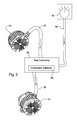
- Fig. 2
- is a schematic diagram of a system for adjusting clip frequency of a reel mower cutting unit in one embodiment of the invention.
- Fig. 3
- is a block diagram of software for a system and method for adjusting clip frequency of a reel mower cutting unit according to a preferred method of the present invention.
- In the embodiment of
Fig. 1 , walk behindgreensmower 10 is shown having reelmower cutting unit 12. The walk behind greensmower may be powered byinternal combustion engine 16 or an alternative power source such as an electric battery and motor. The walk behind greensmower also includeshandle assembly 18 andframe 20. The frame may include a forwardly extending U-shapedframe member 21. The frame may be supported, at least in part, bytraction drum 22 operably coupled to the engine and rotated to move the machine forward during mowing operations. The drive system may include one or more pulleys and/or gears between theengine 16 andtraction drum 22. - In one embodiment, the engine may be coupled by a pulley and belt arrangement, or other power transmission device, to
alternator 23. During operation of theengine 16, thealternator 23 may produce a voltage carried onvoltage bus 25 that varies in relation to the engine speed. For example, the bus voltage may be between about 18 volts and about 70 volts. The operator may control the engine speed withthrottle lever 27. - Although the system and method for adjusting frequency of clip is described for a walk behind greensmower, it will be understood by those skilled in the art that the system and method also may be used on any other grass mowing machine having one or more reel mower cutting units. For example, the system and method may be used for reel mower cutting units on triplex riding greensmowers, fairway mowers, and trim mowers.
- In one embodiment, reel
mower cutting unit 12 may be rotated byelectric reel motor 24 mounted to the left or right side of the cutting unit. The electric reel motor may be connected viaelectric cable 26 to reelmotor controller 28. In response to voltage output from the reel motor controller, the electric reel motor rotates the blades of cutting reel 34 about a generally horizontal and laterally extending axis. Grass may be cut between rotating reel blades of cutting reel 34 and a bedknife mounted between the side panels. - In one embodiment, the reel mower cutting unit may be supported by non-powered front and
rear rollers - As shown in
Fig. 2 , a preferred embodiment of a system for adjusting frequency of clip of a reel mower cutting unit includes reel motor controller 31 mounted on a grass mowing machine. The reel motor controller may have one or multiple analog and digital inputs includingvoltage bus 25 fromalternator 23, one or multiple output drivers includingoutput driver 26 to reelmotor 24, and embeddedsoftware 36 which can implement the steps of the frequency of clip adjustment system. - In one embodiment, frequency of
clip user interface 46 provides a voltage input to the reel motor controller throughvehicle harness 48. The frequency of clip user interface may be a knob, dial or switch that includes multiple settings for the frequency of clip. The user interface may provide several discrete frequency of clip settings, or may provide infinitely variable settings between a minimum and maximum frequency of clip. - In one embodiment, the user interface may be a potentiometer that can vary a voltage input to the reel motor controller. For example, the operator may use the user interface to specify one of multiple frequency of clip settings between about 0.16 inches and about 0.48 inches for an eleven blade reel, or between about 0.25 inches and about 0.75 inches for a seven blade reel. Each frequency of clip setting selected by the operator may specify a corresponding voltage input of between about 1 volt and about 5 volts that is provided to the reel motor controller.
- Now referring to
Fig. 3 , embedded software that may be used to implement the frequency of clip adjustment system and method are shown in block diagram form. - In
block 101, the operating system/task scheduler specifies when the controller shall run the frequency of clip system at each clock cycle or periodic interval during machine operation, such as every 50 milliseconds. Inblock 102, variables of the system are initialized, including but not limited to engine to drum ratio, walk speed, reel speed and engine speed. - In
block 103, the reel motor controller reads the alternator voltage onvoltage bus 25. For example, each bus voltage reading may be between about 18 volts and about 70 volts. - In
block 104, a scale factor for reel load may be applied to the actual or new bus voltage reading fromblock 103. The scale factor may reduce the effect of any sudden and/or very brief voltage changes which do not indicate a sustained change in the load on the engine and/or alternator. However, if the reel mower encounters an increased load for a sustained period, such as heavy and thick grass or a steep incline, the actual or new voltage reading will be used. - For example, the scale factor may compare each new voltage bus reading to one or more prior voltage bus readings. If the actual or new voltage bus reading is not greatly different from one or more prior readings, indicating changes in the voltage bus reading are sustained, a scale factor of 1 may be used. However, if the actual or new voltage bus reading has greatly increased or decreased from a previous reading(s), a scale factor may be applied. For example, if the actual or new voltage bus reading is at least 10% higher than the previous reading, the scale factor may be a ratio of the old voltage bus reading to the actual or new reading. The scale factor may be applied to reduce the actual or new voltage bus reading. Conversely, if the actual or new voltage bus reading is at least 10% lower than the previous reading, the scale factor may be a ratio of the actual or new voltage bus reading to the previous reading. The scale factor may be applied to increase the actual or new voltage bus reading.
- In one embodiment, in
block 105, the controller maps the scaled bus voltage to a table which identifies the engine speed or rpm for each such voltage. Inblock 106, the controller calculates the travel speed of the machine. In the case of a walk behind greensmower, the travel speed of the machine also may be referred to as the walk speed. The walk speed of a walk behind greensmower in miles per hour may be calculated based on the engine speed determined inblock 105, and other numerical constants specific to the reel mower cutting unit, using the following equation: ((ENGINE RPM / ENGINE TO TRACTION DRUM RATIO) x DRUM CIRCUMFERENCE x 60)/63360. - The engine to traction drum ratio and drum circumference may be numerical constants stored in the reel motor controller. The engine to traction drum ratio for a walk behind greensmower is typically between about 10 and about 30, based on the diameter of the traction drum, the engine crank pulley, gearbox pulley, and traction drum output shaft.
- For example, if the engine speed of a walk behind greensmower is determined to be 2000 rpm in
block 104, the traction drum has a 23.56 inch circumference, and the engine to traction drum ratio is 19.68, the walk speed may be calculated as follows: ((2000 rpm / 19.68) x 23.56 inches x 60 minutes per hour) / 63360 inches per mile = 2.26 mph. - In
block 107, a frequency of cut setting may be a voltage output provided by the user interface to the reel motor controller. For example, the user interface may include a potentiometer that can vary the voltage provided to the reel motor controller between a maximum of about 5 volts and a minimum of about 1 volt. Inblock 108, the reel motor controller uses the voltage output reading from the user interface inblock 107 to specify the frequency of clip setting. - In one embodiment, the reel motor controller may map the voltage output from the user interface to one of several frequency clip presets. For example, an eleven blade cutting reel may have five or more presets between about 0.16 inches and about 0.48 inches for the minimum and maximum voltage signals from the user interface.
- Similarly, a seven blade cutting reel may have five or more presets between about 0.251 inches and about 0.754 inches for the minimum and maximum voltage signals. Alternatively, the frequency of clip may be infinitely variable between maximum and minimum settings.
- In
block 109, the reel motor controller determines the required reel speed based on the walk speed calculated inblock 106, the frequency of clip setting specified inblock 108, and one or more other numerical constants specific to the reel mower cutting unit, including but not limited to the number of reel blades on the cutting unit. For example, the required reel speed of a walk behind greensmower in miles per hour may be calculated using the following equation: ((63360 / 60) x WALK SPEED) / (NUMBER OF REEL BLADES x FREQUENCY OF CUT). - The number of reel blades may be a constant stored in the reel motor controller and/or input by the operator. If the walk speed of a walk behind greensmower is determined in
block 106 to be 2.26 mph, the cutting unit has 7 reel blades, and the operator specifies a frequency of cut of 0.425 inches, the required reel speed may be calculated as follows: ((63360 inches per mile / 60 seconds per minute) x 2.26 mph) / (7 x 0.425 inches) = 802 rpm. - In block 210, the reel motor controller returns a reel speed signal to the reel motor. For example, the reel speed output may be between about 20 volts and about 60 volts.
- Having described a preferred embodiment, it will become apparent that various modifications can be made without departing from the scope of the invention as defined in the accompanying claims.
Claims (10)
- A frequency of clip adjustment system for a reel mower cutting unit (12), characterized by an electric reel motor (24) attached to the reel mower cutting unit (12) for rotating a cutting reel at a plurality of different rotational speeds; an alternator (23) rotatably driven by an internal combustion engine (16) and connected to a voltage bus (25) to provide a voltage based on the speed of the engine (16); a user interface (46) having a plurality of frequency of clip settings, each setting corresponding to a voltage output; and a reel motor controller (28) connected to the voltage bus (25) and reading the voltage provided by the alternator (23), connected to the user interface (46) and reading the voltage from the user interface (46), and connected to the electric reel motor (24) and providing a rotational speed to the electric reel motor (24) based on the alternator voltage, voltage output from the user interface (46), and other numerical constants specific to the reel mower cutting unit (12).
- The frequency of clip adjustment system according to claim, characterized in that the user interface (46) has a plurality of discrete frequency of clip settings, each setting corresponding to a voltage.
- The frequency of clip adjustment system according to claim 1 or 2, characterized by a traction drum (22) rotated by the engine (16) to propel the reel mower cutting unit (12) forward.
- The frequency of clip adjustment system according to one or several of the previous claims, characterized by a table stored in reel motor controller (28) mapping the voltage reading on the voltage bus (25) to an engine speed.
- The frequency of clip adjustment system according to claim 4, characterized by a scale factor applied to the voltage reading on the voltage bus (25) based on the difference between the voltage reading and at least one previous voltage reading.
- The frequency of clip adjustment system according to one or several of the previous claims, characterized in that the numerical constants include an engine to drum ratio, a drum circumference, and the number of blades on the cutting reel.
- A frequency of clip adjustment method for a reel mower cutting unit (12) characterized by the steps of reading a voltage on a voltage bus (25) ; mapping the voltage to an engine speed; calculating a travel speed of the reel mower cutting unit (12) based on the engine speed and numerical constants specific to the reel mower cutting unit (12); reading a voltage provided by an operator interface (46) corresponding to a frequency of clip setting selected by an operator on the operator interface (46); and calculating the required reel speed based on the travel speed, the frequency of clip setting, and numerical constants specific to the reel mower cutting unit (12).
- The frequency of clip adjustment method according to claim 7, characterized by the step of applying a scale factor to the voltage on the voltage bus (25), the scale factor based at least in part on the difference between the voltage and at least one previous voltage on the voltage bus (25).
- The frequency of clip adjustment method according to claim 7 or 8, characterized by mapping the voltage provided by the operator interface (46) to one of a plurality of discrete frequency of cut settings.
- The frequency of clip adjustment method according to one or several of the claim 7 to 9, characterized in that the numerical constants specific to the reel mower cutting unit (12) include an engine to drum ratio, a drum circumference and a number of reel blades.
Applications Claiming Priority (1)
| Application Number | Priority Date | Filing Date | Title |
|---|---|---|---|
| US12/020,245 US7954308B2 (en) | 2008-01-25 | 2008-01-25 | Frequency of clip adjustment system and method for reel mower cutting unit |
Publications (3)
| Publication Number | Publication Date |
|---|---|
| EP2082639A2 true EP2082639A2 (en) | 2009-07-29 |
| EP2082639A3 EP2082639A3 (en) | 2017-03-22 |
| EP2082639B1 EP2082639B1 (en) | 2018-05-16 |
Family
ID=40613002
Family Applications (1)
| Application Number | Title | Priority Date | Filing Date |
|---|---|---|---|
| EP09150990.1A Ceased EP2082639B1 (en) | 2008-01-25 | 2009-01-21 | Frequency of clip adjustment system and method for reel mower cutting unit |
Country Status (2)
| Country | Link |
|---|---|
| US (1) | US7954308B2 (en) |
| EP (1) | EP2082639B1 (en) |
Families Citing this family (12)
| Publication number | Priority date | Publication date | Assignee | Title |
|---|---|---|---|---|
| US20110061355A1 (en) * | 2009-09-16 | 2011-03-17 | Griffin Randall J | Grass mowing machine with engine speed and voltage limiter |
| US8261523B2 (en) * | 2010-02-04 | 2012-09-11 | The Toro Company | Clip control system for walk reel mower |
| US9338940B2 (en) | 2014-02-27 | 2016-05-17 | Honda Motor Co., Ltd. | Drive systems and methods for implementing engine stall protection in a self-propelled machine |
| US9635809B2 (en) * | 2014-06-10 | 2017-05-02 | Textron Inc. | Electronic control for a grass cutting reel assembly of a lawn-care vehicle |
| US10264726B2 (en) | 2014-09-17 | 2019-04-23 | Deere & Company | Frequency of clip control system |
| FR3054774B1 (en) | 2016-08-02 | 2019-05-17 | Rousseau | THERMAL TYPE LOADING DEVICE HAVING CUTTING / GRINDING EQUIPMENT ACTED IN ACTION USING AN ELECTRIC MOTOR |
| US10356977B2 (en) | 2017-06-13 | 2019-07-23 | Deere + Company | Electric walk behind greens mower |
| US11206759B2 (en) | 2017-11-21 | 2021-12-28 | The Toro Company | Mower quick height of cut adjustment |
| US10813284B2 (en) | 2018-07-02 | 2020-10-27 | Deere & Company | Electric walk behind greens mower |
| US12527251B2 (en) | 2022-10-05 | 2026-01-20 | Deere & Company | Radial frequency of clip control system |
| US12466480B2 (en) | 2022-10-05 | 2025-11-11 | Deere & Company | Radial differential speed control system |
| US12501851B2 (en) | 2022-10-19 | 2025-12-23 | Deere & Company | Mower slope sensing system |
Citations (2)
| Publication number | Priority date | Publication date | Assignee | Title |
|---|---|---|---|---|
| US5394678A (en) | 1992-01-03 | 1995-03-07 | The Toro Company | Electronic control for turf maintenance vehicle |
| US7168227B2 (en) | 2004-05-21 | 2007-01-30 | Textron Inc. | Internal combustion engine traction drive with electric cutting unit drive for walking greens mower |
Family Cites Families (13)
| Publication number | Priority date | Publication date | Assignee | Title |
|---|---|---|---|---|
| GB2121629B (en) * | 1982-05-18 | 1985-10-23 | Standard Telephones Cables Ltd | Temperature controlled crystal oscillator |
| US5406778A (en) * | 1994-02-03 | 1995-04-18 | Ransomes America Corporation | Electric drive riding greens mower |
| US6082084A (en) * | 1995-11-13 | 2000-07-04 | Ransomes America Corporation | Electric riding mower with electric steering system |
| US5794422A (en) * | 1995-11-13 | 1998-08-18 | Ransomes America Corporation | Electric drive mower with motor generator set |
| EP0959660B1 (en) * | 1996-02-09 | 2003-06-25 | The Toro Company | Electric drive riding mower |
| US6571542B1 (en) * | 1999-03-25 | 2003-06-03 | Textron Inc. | Electric drive mower with interchangeable power sources |
| US6591593B1 (en) * | 2000-10-23 | 2003-07-15 | Dennis Brandon | Electric riding lawn mower powered by an internal combustion engine and generator system |
| US6523334B1 (en) | 2000-10-26 | 2003-02-25 | Textron Inc. | Battery-powered walk-behind greensmower |
| US7007446B2 (en) * | 2000-10-26 | 2006-03-07 | Textron Inc. | Battery-powered walk-behind greensmower |
| US6487837B1 (en) | 2001-06-05 | 2002-12-03 | Textron Inc. | Articularly mounted battery-powered walk-behind reel lawnmower |
| US7265607B1 (en) * | 2004-08-31 | 2007-09-04 | Intel Corporation | Voltage regulator |
| US7367173B2 (en) * | 2005-03-02 | 2008-05-06 | Textron Inc. | Greens mower data display and controller |
| US7677017B2 (en) * | 2005-06-28 | 2010-03-16 | Textron Innovations Inc. | Modular power source for walk-behind mower |
-
2008
- 2008-01-25 US US12/020,245 patent/US7954308B2/en active Active
-
2009
- 2009-01-21 EP EP09150990.1A patent/EP2082639B1/en not_active Ceased
Patent Citations (2)
| Publication number | Priority date | Publication date | Assignee | Title |
|---|---|---|---|---|
| US5394678A (en) | 1992-01-03 | 1995-03-07 | The Toro Company | Electronic control for turf maintenance vehicle |
| US7168227B2 (en) | 2004-05-21 | 2007-01-30 | Textron Inc. | Internal combustion engine traction drive with electric cutting unit drive for walking greens mower |
Also Published As
| Publication number | Publication date |
|---|---|
| EP2082639B1 (en) | 2018-05-16 |
| US20090188225A1 (en) | 2009-07-30 |
| US7954308B2 (en) | 2011-06-07 |
| EP2082639A3 (en) | 2017-03-22 |
Similar Documents
| Publication | Publication Date | Title |
|---|---|---|
| US7954308B2 (en) | Frequency of clip adjustment system and method for reel mower cutting unit | |
| US7594377B1 (en) | Means of adjusting ground speed of a vehicle based on load on blade assembly | |
| EP2260686B1 (en) | Hole spacing control system and aerator | |
| US6892517B2 (en) | Blade and ground speed control system | |
| US10709061B2 (en) | Electric power equipment | |
| US10264726B2 (en) | Frequency of clip control system | |
| US10158302B2 (en) | Electric power equipment | |
| US10617058B2 (en) | Anticipative electric mower and method of piloting such a mower | |
| CN102686100B (en) | lawn mowing vehicle | |
| EP1698221B1 (en) | Greens mower | |
| KR100659019B1 (en) | Internal combustion engine traction drive with electric cutting unit drive for walking greens mower | |
| EP2105337A1 (en) | Electronic engine speed control system for a grass mowing machine | |
| US9635806B2 (en) | Mower blade speed control system | |
| US20030172635A1 (en) | Grass-Cutting tractor with improved operating features | |
| US20150227120A1 (en) | Method For Optimizing An Operating Function Of A Ground Milling Machine And Ground Milling Machine | |
| JP5658880B2 (en) | Lawn mower | |
| JP5783678B2 (en) | Lawn mower | |
| CN116076227A (en) | Novel remote control mechanism of mower | |
| EP2353361B1 (en) | Height of cut adjuster assembly for a reel mower cutting unit | |
| JP5771356B2 (en) | Riding lawn mower | |
| US12439848B2 (en) | Ground working vehicle with adjustable implement | |
| US20250063982A1 (en) | Outdoor power equipment with unequal blade rpm control | |
| CN107836209A (en) | A kind of hay mover and sensor height control method | |
| CN117561871A (en) | Remote control mower control mechanism | |
| CN105830624B (en) | Brake structure and its grass trimmer |
Legal Events
| Date | Code | Title | Description |
|---|---|---|---|
| PUAI | Public reference made under article 153(3) epc to a published international application that has entered the european phase |
Free format text: ORIGINAL CODE: 0009012 |
|
| AK | Designated contracting states |
Kind code of ref document: A2 Designated state(s): AT BE BG CH CY CZ DE DK EE ES FI FR GB GR HR HU IE IS IT LI LT LU LV MC MK MT NL NO PL PT RO SE SI SK TR |
|
| AX | Request for extension of the european patent |
Extension state: AL BA RS |
|
| REG | Reference to a national code |
Ref country code: DE Ref legal event code: R079 Ref document number: 602009052288 Country of ref document: DE Free format text: PREVIOUS MAIN CLASS: A01D0034470000 Ipc: A01D0034580000 |
|
| PUAL | Search report despatched |
Free format text: ORIGINAL CODE: 0009013 |
|
| AK | Designated contracting states |
Kind code of ref document: A3 Designated state(s): AT BE BG CH CY CZ DE DK EE ES FI FR GB GR HR HU IE IS IT LI LT LU LV MC MK MT NL NO PL PT RO SE SI SK TR |
|
| AX | Request for extension of the european patent |
Extension state: AL BA RS |
|
| RIC1 | Information provided on ipc code assigned before grant |
Ipc: A01D 34/58 20060101AFI20170214BHEP Ipc: A01D 34/47 20060101ALI20170214BHEP |
|
| 17P | Request for examination filed |
Effective date: 20170922 |
|
| RBV | Designated contracting states (corrected) |
Designated state(s): AT BE BG CH CY CZ DE DK EE ES FI FR GB GR HR HU IE IS IT LI LT LU LV MC MK MT NL NO PL PT RO SE SI SK TR |
|
| AKX | Designation fees paid |
Designated state(s): DE GB |
|
| AXX | Extension fees paid |
Extension state: BA Extension state: AL Extension state: RS |
|
| GRAP | Despatch of communication of intention to grant a patent |
Free format text: ORIGINAL CODE: EPIDOSNIGR1 |
|
| INTG | Intention to grant announced |
Effective date: 20171204 |
|
| GRAS | Grant fee paid |
Free format text: ORIGINAL CODE: EPIDOSNIGR3 |
|
| GRAA | (expected) grant |
Free format text: ORIGINAL CODE: 0009210 |
|
| AK | Designated contracting states |
Kind code of ref document: B1 Designated state(s): DE GB |
|
| REG | Reference to a national code |
Ref country code: GB Ref legal event code: FG4D |
|
| REG | Reference to a national code |
Ref country code: DE Ref legal event code: R096 Ref document number: 602009052288 Country of ref document: DE |
|
| REG | Reference to a national code |
Ref country code: DE Ref legal event code: R097 Ref document number: 602009052288 Country of ref document: DE |
|
| PLBE | No opposition filed within time limit |
Free format text: ORIGINAL CODE: 0009261 |
|
| STAA | Information on the status of an ep patent application or granted ep patent |
Free format text: STATUS: NO OPPOSITION FILED WITHIN TIME LIMIT |
|
| 26N | No opposition filed |
Effective date: 20190219 |
|
| PGFP | Annual fee paid to national office [announced via postgrant information from national office to epo] |
Ref country code: DE Payment date: 20191219 Year of fee payment: 12 |
|
| REG | Reference to a national code |
Ref country code: DE Ref legal event code: R119 Ref document number: 602009052288 Country of ref document: DE |
|
| PG25 | Lapsed in a contracting state [announced via postgrant information from national office to epo] |
Ref country code: DE Free format text: LAPSE BECAUSE OF NON-PAYMENT OF DUE FEES Effective date: 20210803 |
|
| PGFP | Annual fee paid to national office [announced via postgrant information from national office to epo] |
Ref country code: GB Payment date: 20240129 Year of fee payment: 16 |
|
| GBPC | Gb: european patent ceased through non-payment of renewal fee |
Effective date: 20250121 |
|
| PG25 | Lapsed in a contracting state [announced via postgrant information from national office to epo] |
Ref country code: GB Free format text: LAPSE BECAUSE OF NON-PAYMENT OF DUE FEES Effective date: 20250121 |