EP2082610B1 - Headset with adjustable earhook - Google Patents
Headset with adjustable earhook Download PDFInfo
- Publication number
- EP2082610B1 EP2082610B1 EP07817826A EP07817826A EP2082610B1 EP 2082610 B1 EP2082610 B1 EP 2082610B1 EP 07817826 A EP07817826 A EP 07817826A EP 07817826 A EP07817826 A EP 07817826A EP 2082610 B1 EP2082610 B1 EP 2082610B1
- Authority
- EP
- European Patent Office
- Prior art keywords
- headset
- earhook
- slider
- headset according
- speaker
- Prior art date
- Legal status (The legal status is an assumption and is not a legal conclusion. Google has not performed a legal analysis and makes no representation as to the accuracy of the status listed.)
- Active
Links
Images
Classifications
-
- H—ELECTRICITY
- H04—ELECTRIC COMMUNICATION TECHNIQUE
- H04R—LOUDSPEAKERS, MICROPHONES, GRAMOPHONE PICK-UPS OR LIKE ACOUSTIC ELECTROMECHANICAL TRANSDUCERS; ELECTRIC HEARING AIDS; PUBLIC ADDRESS SYSTEMS
- H04R1/00—Details of transducers, loudspeakers or microphones
- H04R1/10—Earpieces; Attachments therefor ; Earphones; Monophonic headphones
- H04R1/1058—Manufacture or assembly
- H04R1/1066—Constructional aspects of the interconnection between earpiece and earpiece support
-
- H—ELECTRICITY
- H04—ELECTRIC COMMUNICATION TECHNIQUE
- H04R—LOUDSPEAKERS, MICROPHONES, GRAMOPHONE PICK-UPS OR LIKE ACOUSTIC ELECTROMECHANICAL TRANSDUCERS; ELECTRIC HEARING AIDS; PUBLIC ADDRESS SYSTEMS
- H04R1/00—Details of transducers, loudspeakers or microphones
- H04R1/10—Earpieces; Attachments therefor ; Earphones; Monophonic headphones
- H04R1/105—Earpiece supports, e.g. ear hooks
-
- H—ELECTRICITY
- H04—ELECTRIC COMMUNICATION TECHNIQUE
- H04R—LOUDSPEAKERS, MICROPHONES, GRAMOPHONE PICK-UPS OR LIKE ACOUSTIC ELECTROMECHANICAL TRANSDUCERS; ELECTRIC HEARING AIDS; PUBLIC ADDRESS SYSTEMS
- H04R2201/00—Details of transducers, loudspeakers or microphones covered by H04R1/00 but not provided for in any of its subgroups
- H04R2201/10—Details of earpieces, attachments therefor, earphones or monophonic headphones covered by H04R1/10 but not provided for in any of its subgroups
- H04R2201/109—Arrangements to adapt hands free headphones for use on both ears
Definitions
- EP 0 749 263 B1 , US 2003/0013498 A1 and WO 03/009637 all disclose headsets according to the preamble of claim 1. These documents disclose headsets, which in different ways can be adjusted to the user. However, there is room for improvement. The head anatomy varies a lot between individuals and especially the distance between the auditory canal and top of the ear and the angle of an imaginary line extending between the auditory canal and the mouth varies. It is therefore desirable to be able to adjust the headset regarding these parameters.
- the object of the invention is to provide a headset with good adjustability.
- the headset according to the invention is characterised in that the attachment means are adapted such that the distance between the attachment position of the earhook and the speaker can be varied in order to adapt the headset to the user. In this way, an improved and simple manner of adjusting the headset to the anatomy of a specific user is obtained.
- the holes extend essentially perpendicular on an axis running between the first end and the second end of the headset body.
- the earhook comprises a first linear portion to be received by the holes, which first linear portion of the earhook is connected by a hinge to the remainder of the earhook.
- the holding means comprises a slider that can slide along the headset body.
- the portion 7 of the earhook 2 should be inserted in the first hole 5, and if the user has a relatively large ear, the portion should be inserted in the second hole 6.
- the portion 7 and the holes 5, 6 have a non-circular cross-section, and the portion 7 is therefore not able to rotate.
- one side of the portion 7 is provided with a notch 11.
- the internal wall of the holes 5, 6 is provided with a not shown protrusion that is adapted to engage the notch 11 and prevent the portion 7 from leaving the hole 5, 6 unintentionally.
- the earhook portion 7 could be held in the holes by pure friction.
- headset body 15 can be provided with more than two holes.
- the holes 5, 6 are through going. This means, that the headset can be used on left or right ear.
- the markings L and R indicates from which side the earhook 2 should be inserted in order to wear the headset on the left or right ear respectively.
- Fig. 1 provides two positions at which the earhook 2 can be attached to the headset body 15.
- Figs. 3 and 4 disclose embodiments where the distance between the attachment point and the speaker can be adjusted more precisely.
- the earhook 2 is attached to a slider 22 that is arranged inside the headset body 15.
- the earhook extends from the slider 22 through a longitudinal slot 23 in the body wall.
- the slider 22 can be provided with a protrusion 18 that engages one of several indentations 19 on the inner side of the body wall in order to avoid unintentional sliding of the slider 22.
- the slider 22 could be provided with indentations and the inner side of the body wall with a protrusion.
- unintentionally movement of the slider could be prevented by pure friction between the slider 22 and the headset body 15.
Landscapes
- Engineering & Computer Science (AREA)
- Manufacturing & Machinery (AREA)
- Physics & Mathematics (AREA)
- Acoustics & Sound (AREA)
- Signal Processing (AREA)
- Headphones And Earphones (AREA)
- Telephone Set Structure (AREA)
Abstract
Description
- The invention relates to a headset comprising a headset body and an earhook, wherein the headset body includes a microphone, a speaker and attachment means for attaching the earhook to the headset body between the microphone and the speaker at an attachment position that lies at a distance from the speaker. Such headsets are primarily used as headsets for telephony. The headset is attached to the ear of the user by means of the earhook such that the speaker lies at the entrance of the auditory canal and the microphone more or less close to the mouth.
-
EP 0 749 263 B1 ,US 2003/0013498 A1 andWO 03/009637 - The object of the invention is to provide a headset with good adjustability. The headset according to the invention is characterised in that the attachment means are adapted such that the distance between the attachment position of the earhook and the speaker can be varied in order to adapt the headset to the user. In this way, an improved and simple manner of adjusting the headset to the anatomy of a specific user is obtained.
- According to an embodiment the headset body has a first end and a second end, wherein the microphone is arranged at the first end and the speaker is arranged at the second end. Preferably, the headset body is an elongate body extending between the first end and the second end.
- According to an embodiment, the attachment means are adapted such that the earhook can be attached at two or more distinct distances from the second end. This is a simple and in many cases satisfying solution.
- According to a preferred embodiment, the attachment means comprises at least two holes for receiving a portion of the ear hook. This is a very simple and reliable solution.
- Preferably, the holes extend essentially perpendicular on an axis running between the first end and the second end of the headset body.
- The holes can be through going holes. Thus, the headset may be used on both ears as the earhook portion can be inserted from either side.
- According to a simple embodiment, the portion of the earhook is held in one the holes by friction.
- According to an embodiment, the earhook comprises a first linear portion to be received by the holes, which first linear portion of the earhook is connected by a hinge to the remainder of the earhook.
- According to an embodiment, the earhook is at least partly made of material making it plastically deformable in order to adapt it to the user.
- According to an alternative embodiment, the holding means comprises a slider that can slide along the headset body.
- According to a specific embodiment the slider can be arranged inside the headset body and the earhook can extend from the slider through a slot in the wall of the headset body to the outside.
- Alternatively, the slider is in the shape of a sleeve, which is arranged around the headset body. In this case, the headset body may be shaped as an elongate boom. If the book has a circular cross-section, the slider may rotate around the boom, which adds to the adjustability. If the boom has a non-circular cross-section, the slider may be prevented from undesired rotation.
- The slider can be frictionally held when no external force is applied.
- Alternatively or additionally, the contacting surfaces of the slider and the headset body are provided with inter-engaging teeth and/or indentations. Thus, undesired sliding of the slider is prevented in a simple and reliable way.
- The invention is explained in details below with reference to the drawing illustrating embodiments of the invention and in which
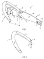
- Fig. 1
- is a perspective view of a first embodiment of a headset according to the invention,
- Fig. 2
- is a perspective view of an ear hook of the headset according to the invention,
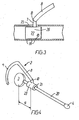
- Fig. 3
- is a cross-sectional view through a second embodiment of the invention, and
- Fig.4
- is a perspective view of a third embodiment of a headset according to the invention.
- The following reference signs are used in the figures and the following detailed description of the preferred embodiments.
- 1
- headset
- 2
- earhook
- 3
- speaker
- 4
- microphone
- 5
- first hole
- 6
- second hole
- 7
- first linear portion of earhook
- 8
- second linear portion of earhook
- 9
- curved portion of earhook
- 10
- ear hook hinge
- 11
- notch
- 12
- dome-shaped protrusion
- 13
- speaker hole
- 14
- microphone hole
- 15
- headset body
- 16
- first end of headset body
- 17
- second end of headset body
- 18
- first side of headset body
- 19
- second side of headset body
- 20
- boom
- 21
- slider
- 22
- slider
- 23
- slot
- 24
- markings
- 25
- attachment position
-
Fig. 1 shows a headset 1 according to a first embodiment of the invention. The headset 1 comprises aheadset body 15 and anearhook 2. Theheadset body 15 is elongate with afirst end 16 and a second end 17. The headset body has afirst side 18 facing the user's head during use and a second side 1-9 facing away from the user's head during use. A microphone 4 is arranged in thefirst end 16 and sound waves can reach the microphone through a microphone hole 14 in thefirst side 18. A dome-shaped protrusion 12 extends from thefirst side 18 of theheadset body 15 at the second end 17. A transducer orspeaker 3 is arranged in theheadset body 15 in this dome-shaped protrusion 12. Sound waves generated by thespeaker 3 can reach the auditory canal of the user through aspeaker hole 13. - Between the
first end 16 and the second end 17 or with other words between themicrophone 3 and the speaker 4 theheadset body 15 is provided with two parallel, transverse through goingholes portion 7 of theearhook 2. The distance d betweenattachment point 25 of the ear-hook 2 and thespeaker 3 depends on thehole earhook 2, which is disclosed in more detail inFig. 2 , comprises a firstlinear portion 7, a secondlinear portion 8 and acurved portion 9. The firstlinear portion 7 is intended for being inserted in one of the twoholes portion 7 of theearhook 2 should be inserted in thefirst hole 5, and if the user has a relatively large ear, the portion should be inserted in thesecond hole 6. Theportion 7 and theholes portion 7 is therefore not able to rotate. As indicated inFig. 2 one side of theportion 7 is provided with a notch 11. The internal wall of theholes portion 7 from leaving thehole earhook portion 7 could be held in the holes by pure friction. - There
headset body 15 can be provided with more than two holes. - The first
linear portion 7 of theearhook 2 is connected by ahinge 10 to the secondlinear portion 8. At the opposite end, the secondlinear portion 8 is continuing into acurved portion 9. Theportions - The shaping properties of the
earhook portions hinge 10 and theholes - As shown in
Fig. 1 , theholes earhook 2 should be inserted in order to wear the headset on the left or right ear respectively. - The embodiment disclosed in
Fig. 1 provides two positions at which theearhook 2 can be attached to theheadset body 15.Figs. 3 and 4 disclose embodiments where the distance between the attachment point and the speaker can be adjusted more precisely. In the embodiment disclosed inFig. 3 theearhook 2 is attached to aslider 22 that is arranged inside theheadset body 15. The earhook extends from theslider 22 through alongitudinal slot 23 in the body wall. As shown, theslider 22 can be provided with aprotrusion 18 that engages one ofseveral indentations 19 on the inner side of the body wall in order to avoid unintentional sliding of theslider 22. On the contrary, theslider 22 could be provided with indentations and the inner side of the body wall with a protrusion. Finally, unintentionally movement of the slider could be prevented by pure friction between theslider 22 and theheadset body 15. -
Fig. 4 discloses a third embodiment, in which the headset body comprises anelongate boom 20 extending between the microphone 4 and thespeaker 3. Theearhook 2 is attached to aslider 21, which is shaped as a sleeve that receives theboom 21. Thesleeve 21 is held in position on theboom 20 by friction and can be forced to move along theboom 20 in order to vary the distance d between theear hook 2 and thespeaker 3. Theboom 20 and the sleeve opening have a circular cross-section such that the earhook can be forced to rotate around theboom 20. Alternatively, theboom 20 and the sleeve opening could have a non-circular cross-section in order to avoid rotation of theearhook 2 completely. - The invention is not limited to the disclosed embodiments.
- The phrase "attachment means" covers all possible means of attaching the ear hook to the headset body, the essential feature being that the distance between the attachment point of the earhook and the speaker can be varied. Thus, the phrase "attachment means" could be replaced by the term "fastener", "holder" or the like.
Claims (18)
- A headset (1) comprising a headset body (15, 20) and an earhook (2), wherein the headset body (15, 20) includes a microphone (4), a speaker (3) and attachment means (5, 6, 21, 22) for attaching the earhook (2) to the headset body (15, 20) between the microphone (4) and the speaker (3) at an attachment position (25) that lies at a distance (d) from the speaker (3), characterised in that the attachment means (5, 6, 21, 22) are adapted such that the distance (d) between the attachment position (25) and the speaker (3) can be varied in order to adapt the headset to the user.
- A headset according to claim 1, wherein the headset body (15, 20) has a first end (16) and a second end (17), wherein the microphone (4) is arranged at the first end (16) and the speaker (3) is arranged at the second end (17).
- A headset according to claim 2, wherein the headset body is an elongate body (15, 20) extending between the first end (16) and the second end (17).
- A headset according to one of the preceding claims, wherein the attachment means (5, 6, 21, 22) are adapted such that the earhook (2) can be held at two or more distinct distances (d) from the second end (17).
- A headset according to claim 4, wherein the attachment means comprise at least two holes (5, 6) for receiving a portion (7) of the ear hook (2).
- A headset according to claim 5, wherein the holes (5, 6) extend essentially perpendicular on an axis running between the first end (16) and the second end (17).
- A headset according to claim 6, wherein the holes (5, 6) are through holes.
- A headset according to one of the claims 5-7, wherein the portion (7) of the earhook (2) is held in the holes (5, 6) by friction.
- A headset according to any of the claims 5-8, wherein the earhook (2) comprises a first linear portion (7) to be received by the holes (5, 6), which first linear portion of earhook (2) is connected by a hinge (10) to the remainder of the earhook (2).
- A headset according to any of the preceding claims, wherein the earhook (2) at least partly is made of material making it plastically deformable in order to adapt it to the user.
- A headset according to any of the claims 1-3, wherein the attachment means comprises a slider (21; 22), that can slide along the headset body (15; 20).
- A headset according to claim 11, wherein the slider (22) is arranged inside the headset body (15) and the earhook (2) extends from the slider (22) through a slot (23) in the wall of the headset body (1) to the outside.
- A headset according to claim 11, wherein the slider (21) is in the shape of a sleeve, which is arranged around the headset body (20).
- A headset according to claim 13, wherein the headset body is shaped as an elongate boom (20).
- A headset according to claim 14, wherein the boom (20) has a circular cross-section.
- A headset according to claim 14, wherein the boom (20) has a non-circular cross-section.
- A headset according to any of the claims 11-16, wherein the slider (21; 22) is held by friction, when no external force is applied.
- A headset according to any of the claims 11-17, wherein the contacting surfaces of the slider (21; 22) and the headset body (15; 20) are provided with inter-engaging teeth and/or indentations (18, 19).
Applications Claiming Priority (2)
| Application Number | Priority Date | Filing Date | Title |
|---|---|---|---|
| DK200601332A DK200601332A (en) | 2006-10-13 | 2006-10-13 | Headset with adjustable ear hook |
| PCT/DK2007/000430 WO2008043359A1 (en) | 2006-10-13 | 2007-10-05 | Headset with adjustable earhook |
Publications (2)
| Publication Number | Publication Date |
|---|---|
| EP2082610A1 EP2082610A1 (en) | 2009-07-29 |
| EP2082610B1 true EP2082610B1 (en) | 2010-07-28 |
Family
ID=38055187
Family Applications (1)
| Application Number | Title | Priority Date | Filing Date |
|---|---|---|---|
| EP07817826A Active EP2082610B1 (en) | 2006-10-13 | 2007-10-05 | Headset with adjustable earhook |
Country Status (5)
| Country | Link |
|---|---|
| EP (1) | EP2082610B1 (en) |
| AT (1) | ATE476063T1 (en) |
| DE (1) | DE602007008129D1 (en) |
| DK (1) | DK200601332A (en) |
| WO (1) | WO2008043359A1 (en) |
Families Citing this family (1)
| Publication number | Priority date | Publication date | Assignee | Title |
|---|---|---|---|---|
| CN105191343A (en) * | 2013-03-14 | 2015-12-23 | 哈曼国际工业有限公司 | Behind the ear earphone |
Family Cites Families (4)
| Publication number | Priority date | Publication date | Assignee | Title |
|---|---|---|---|---|
| DK0749263T3 (en) * | 1995-06-13 | 2000-01-31 | Gn Netcom As | Headphone with adjustable ear hook |
| US5761298A (en) * | 1996-05-31 | 1998-06-02 | Plantronics, Inc. | Communications headset with universally adaptable receiver and voice transmitter |
| GB2347042B (en) * | 1999-02-16 | 2001-04-18 | Cotron Corp | Adjustable earphone with a microphone |
| EP1215932A1 (en) * | 2000-12-07 | 2002-06-19 | Everspring Industry Co. Ltd. | Wireless hanging type earphone |
-
2006
- 2006-10-13 DK DK200601332A patent/DK200601332A/en not_active Application Discontinuation
-
2007
- 2007-10-05 EP EP07817826A patent/EP2082610B1/en active Active
- 2007-10-05 DE DE602007008129T patent/DE602007008129D1/en active Active
- 2007-10-05 WO PCT/DK2007/000430 patent/WO2008043359A1/en not_active Ceased
- 2007-10-05 AT AT07817826T patent/ATE476063T1/en not_active IP Right Cessation
Also Published As
| Publication number | Publication date |
|---|---|
| DK200601332A (en) | 2008-04-14 |
| DE602007008129D1 (en) | 2010-09-09 |
| EP2082610A1 (en) | 2009-07-29 |
| ATE476063T1 (en) | 2010-08-15 |
| WO2008043359A1 (en) | 2008-04-17 |
Similar Documents
| Publication | Publication Date | Title |
|---|---|---|
| EP2198629B1 (en) | Earphone device with bi-stable conchal wall stabilizer | |
| US10231048B2 (en) | Ergonomic earpiece with attachment mount | |
| US6496589B1 (en) | Headset with overmold | |
| EP2081404B1 (en) | Headphone | |
| EP2177050B1 (en) | Earphone device with ear canal protrusion | |
| US20100061581A1 (en) | Sound producing device | |
| US20130216087A1 (en) | Earbud Positioning Device | |
| EP2963941A1 (en) | A headset with magnetically holding force between headband and microphone arm | |
| EP2028873A1 (en) | Headphone device | |
| US20090116678A1 (en) | Headset with fit adjustments and magnetic accessories | |
| EP4192030B1 (en) | Earpiece | |
| EP3890345B1 (en) | A headset with a double-hinged microphone arm | |
| EP2974360B1 (en) | Behind the ear earphone | |
| WO2002054825A3 (en) | Earring for a headset | |
| US20090103765A1 (en) | Headset for fitting of an earpiece | |
| WO2007105372A1 (en) | Structure for installing bone conduction device on eyeglasses | |
| CN116018821A (en) | Mouth comprising a flexible part and a rigid part of an in-ear audio device | |
| EP2225890B1 (en) | Frame earhook | |
| EP2082610A1 (en) | Headset with adjustable earhook | |
| JP4289376B2 (en) | headset | |
| CN102293014B (en) | Headset | |
| US9125449B1 (en) | Bracket for suspending a wireless cell phone ear piece from a cap | |
| US20070165885A1 (en) | Three-dimensional skin-contact microphone device | |
| AU2007101005A4 (en) | A display attachment for an earphone | |
| CN222563950U (en) | Telescopic ear clip type earphone |
Legal Events
| Date | Code | Title | Description |
|---|---|---|---|
| PUAI | Public reference made under article 153(3) epc to a published international application that has entered the european phase |
Free format text: ORIGINAL CODE: 0009012 |
|
| 17P | Request for examination filed |
Effective date: 20090513 |
|
| AK | Designated contracting states |
Kind code of ref document: A1 Designated state(s): AT BE BG CH CY CZ DE DK EE ES FI FR GB GR HU IE IS IT LI LT LU LV MC MT NL PL PT RO SE SI SK TR |
|
| DAX | Request for extension of the european patent (deleted) | ||
| GRAP | Despatch of communication of intention to grant a patent |
Free format text: ORIGINAL CODE: EPIDOSNIGR1 |
|
| GRAS | Grant fee paid |
Free format text: ORIGINAL CODE: EPIDOSNIGR3 |
|
| GRAA | (expected) grant |
Free format text: ORIGINAL CODE: 0009210 |
|
| AK | Designated contracting states |
Kind code of ref document: B1 Designated state(s): AT BE BG CH CY CZ DE DK EE ES FI FR GB GR HU IE IS IT LI LT LU LV MC MT NL PL PT RO SE SI SK TR |
|
| REG | Reference to a national code |
Ref country code: GB Ref legal event code: FG4D |
|
| REG | Reference to a national code |
Ref country code: CH Ref legal event code: EP |
|
| REG | Reference to a national code |
Ref country code: IE Ref legal event code: FG4D |
|
| REF | Corresponds to: |
Ref document number: 602007008129 Country of ref document: DE Date of ref document: 20100909 Kind code of ref document: P |
|
| REG | Reference to a national code |
Ref country code: NL Ref legal event code: VDEP Effective date: 20100728 |
|
| LTIE | Lt: invalidation of european patent or patent extension |
Effective date: 20100728 |
|
| PG25 | Lapsed in a contracting state [announced via postgrant information from national office to epo] |
Ref country code: LT Free format text: LAPSE BECAUSE OF FAILURE TO SUBMIT A TRANSLATION OF THE DESCRIPTION OR TO PAY THE FEE WITHIN THE PRESCRIBED TIME-LIMIT Effective date: 20100728 Ref country code: FI Free format text: LAPSE BECAUSE OF FAILURE TO SUBMIT A TRANSLATION OF THE DESCRIPTION OR TO PAY THE FEE WITHIN THE PRESCRIBED TIME-LIMIT Effective date: 20100728 Ref country code: AT Free format text: LAPSE BECAUSE OF FAILURE TO SUBMIT A TRANSLATION OF THE DESCRIPTION OR TO PAY THE FEE WITHIN THE PRESCRIBED TIME-LIMIT Effective date: 20100728 Ref country code: NL Free format text: LAPSE BECAUSE OF FAILURE TO SUBMIT A TRANSLATION OF THE DESCRIPTION OR TO PAY THE FEE WITHIN THE PRESCRIBED TIME-LIMIT Effective date: 20100728 |
|
| PG25 | Lapsed in a contracting state [announced via postgrant information from national office to epo] |
Ref country code: IS Free format text: LAPSE BECAUSE OF FAILURE TO SUBMIT A TRANSLATION OF THE DESCRIPTION OR TO PAY THE FEE WITHIN THE PRESCRIBED TIME-LIMIT Effective date: 20101128 Ref country code: PL Free format text: LAPSE BECAUSE OF FAILURE TO SUBMIT A TRANSLATION OF THE DESCRIPTION OR TO PAY THE FEE WITHIN THE PRESCRIBED TIME-LIMIT Effective date: 20100728 Ref country code: PT Free format text: LAPSE BECAUSE OF FAILURE TO SUBMIT A TRANSLATION OF THE DESCRIPTION OR TO PAY THE FEE WITHIN THE PRESCRIBED TIME-LIMIT Effective date: 20101129 Ref country code: CY Free format text: LAPSE BECAUSE OF FAILURE TO SUBMIT A TRANSLATION OF THE DESCRIPTION OR TO PAY THE FEE WITHIN THE PRESCRIBED TIME-LIMIT Effective date: 20100728 Ref country code: BG Free format text: LAPSE BECAUSE OF FAILURE TO SUBMIT A TRANSLATION OF THE DESCRIPTION OR TO PAY THE FEE WITHIN THE PRESCRIBED TIME-LIMIT Effective date: 20101028 Ref country code: SI Free format text: LAPSE BECAUSE OF FAILURE TO SUBMIT A TRANSLATION OF THE DESCRIPTION OR TO PAY THE FEE WITHIN THE PRESCRIBED TIME-LIMIT Effective date: 20100728 |
|
| PG25 | Lapsed in a contracting state [announced via postgrant information from national office to epo] |
Ref country code: SE Free format text: LAPSE BECAUSE OF FAILURE TO SUBMIT A TRANSLATION OF THE DESCRIPTION OR TO PAY THE FEE WITHIN THE PRESCRIBED TIME-LIMIT Effective date: 20100728 Ref country code: LV Free format text: LAPSE BECAUSE OF FAILURE TO SUBMIT A TRANSLATION OF THE DESCRIPTION OR TO PAY THE FEE WITHIN THE PRESCRIBED TIME-LIMIT Effective date: 20100728 Ref country code: BE Free format text: LAPSE BECAUSE OF FAILURE TO SUBMIT A TRANSLATION OF THE DESCRIPTION OR TO PAY THE FEE WITHIN THE PRESCRIBED TIME-LIMIT Effective date: 20100728 Ref country code: GR Free format text: LAPSE BECAUSE OF FAILURE TO SUBMIT A TRANSLATION OF THE DESCRIPTION OR TO PAY THE FEE WITHIN THE PRESCRIBED TIME-LIMIT Effective date: 20101029 |
|
| PG25 | Lapsed in a contracting state [announced via postgrant information from national office to epo] |
Ref country code: DK Free format text: LAPSE BECAUSE OF FAILURE TO SUBMIT A TRANSLATION OF THE DESCRIPTION OR TO PAY THE FEE WITHIN THE PRESCRIBED TIME-LIMIT Effective date: 20100728 |
|
| PG25 | Lapsed in a contracting state [announced via postgrant information from national office to epo] |
Ref country code: MC Free format text: LAPSE BECAUSE OF NON-PAYMENT OF DUE FEES Effective date: 20101031 Ref country code: CZ Free format text: LAPSE BECAUSE OF FAILURE TO SUBMIT A TRANSLATION OF THE DESCRIPTION OR TO PAY THE FEE WITHIN THE PRESCRIBED TIME-LIMIT Effective date: 20100728 Ref country code: IT Free format text: LAPSE BECAUSE OF FAILURE TO SUBMIT A TRANSLATION OF THE DESCRIPTION OR TO PAY THE FEE WITHIN THE PRESCRIBED TIME-LIMIT Effective date: 20100728 Ref country code: RO Free format text: LAPSE BECAUSE OF FAILURE TO SUBMIT A TRANSLATION OF THE DESCRIPTION OR TO PAY THE FEE WITHIN THE PRESCRIBED TIME-LIMIT Effective date: 20100728 Ref country code: EE Free format text: LAPSE BECAUSE OF FAILURE TO SUBMIT A TRANSLATION OF THE DESCRIPTION OR TO PAY THE FEE WITHIN THE PRESCRIBED TIME-LIMIT Effective date: 20100728 Ref country code: SK Free format text: LAPSE BECAUSE OF FAILURE TO SUBMIT A TRANSLATION OF THE DESCRIPTION OR TO PAY THE FEE WITHIN THE PRESCRIBED TIME-LIMIT Effective date: 20100728 |
|
| PLBE | No opposition filed within time limit |
Free format text: ORIGINAL CODE: 0009261 |
|
| STAA | Information on the status of an ep patent application or granted ep patent |
Free format text: STATUS: NO OPPOSITION FILED WITHIN TIME LIMIT |
|
| PG25 | Lapsed in a contracting state [announced via postgrant information from national office to epo] |
Ref country code: ES Free format text: LAPSE BECAUSE OF FAILURE TO SUBMIT A TRANSLATION OF THE DESCRIPTION OR TO PAY THE FEE WITHIN THE PRESCRIBED TIME-LIMIT Effective date: 20101108 |
|
| 26N | No opposition filed |
Effective date: 20110429 |
|
| REG | Reference to a national code |
Ref country code: DE Ref legal event code: R097 Ref document number: 602007008129 Country of ref document: DE Effective date: 20110429 |
|
| PG25 | Lapsed in a contracting state [announced via postgrant information from national office to epo] |
Ref country code: IE Free format text: LAPSE BECAUSE OF NON-PAYMENT OF DUE FEES Effective date: 20101005 |
|
| PG25 | Lapsed in a contracting state [announced via postgrant information from national office to epo] |
Ref country code: MT Free format text: LAPSE BECAUSE OF FAILURE TO SUBMIT A TRANSLATION OF THE DESCRIPTION OR TO PAY THE FEE WITHIN THE PRESCRIBED TIME-LIMIT Effective date: 20100728 |
|
| REG | Reference to a national code |
Ref country code: CH Ref legal event code: PL |
|
| PG25 | Lapsed in a contracting state [announced via postgrant information from national office to epo] |
Ref country code: CH Free format text: LAPSE BECAUSE OF NON-PAYMENT OF DUE FEES Effective date: 20111031 Ref country code: LI Free format text: LAPSE BECAUSE OF NON-PAYMENT OF DUE FEES Effective date: 20111031 |
|
| PG25 | Lapsed in a contracting state [announced via postgrant information from national office to epo] |
Ref country code: LU Free format text: LAPSE BECAUSE OF NON-PAYMENT OF DUE FEES Effective date: 20101005 Ref country code: HU Free format text: LAPSE BECAUSE OF FAILURE TO SUBMIT A TRANSLATION OF THE DESCRIPTION OR TO PAY THE FEE WITHIN THE PRESCRIBED TIME-LIMIT Effective date: 20110129 |
|
| PG25 | Lapsed in a contracting state [announced via postgrant information from national office to epo] |
Ref country code: TR Free format text: LAPSE BECAUSE OF FAILURE TO SUBMIT A TRANSLATION OF THE DESCRIPTION OR TO PAY THE FEE WITHIN THE PRESCRIBED TIME-LIMIT Effective date: 20100728 |
|
| REG | Reference to a national code |
Ref country code: FR Ref legal event code: PLFP Year of fee payment: 9 |
|
| REG | Reference to a national code |
Ref country code: FR Ref legal event code: PLFP Year of fee payment: 10 |
|
| REG | Reference to a national code |
Ref country code: FR Ref legal event code: PLFP Year of fee payment: 11 |
|
| REG | Reference to a national code |
Ref country code: FR Ref legal event code: PLFP Year of fee payment: 12 |
|
| P01 | Opt-out of the competence of the unified patent court (upc) registered |
Effective date: 20230522 |
|
| PGFP | Annual fee paid to national office [announced via postgrant information from national office to epo] |
Ref country code: DE Payment date: 20251020 Year of fee payment: 19 |
|
| PGFP | Annual fee paid to national office [announced via postgrant information from national office to epo] |
Ref country code: GB Payment date: 20251020 Year of fee payment: 19 |
|
| PGFP | Annual fee paid to national office [announced via postgrant information from national office to epo] |
Ref country code: FR Payment date: 20251017 Year of fee payment: 19 |
|
| REG | Reference to a national code |
Ref country code: GB Ref legal event code: 732E Free format text: REGISTERED BETWEEN 20260115 AND 20260121 |
|
| REG | Reference to a national code |
Ref country code: DE Ref legal event code: R081 Ref document number: 602007008129 Country of ref document: DE Owner name: GN HEARING A/S, DK Free format text: FORMER OWNER: GN NETCOM A/S, BALLERUP, DK |