EP2082143B1 - Combination of a screw, a washer, and a sleeve, and method for the production of such a combination - Google Patents
Combination of a screw, a washer, and a sleeve, and method for the production of such a combination Download PDFInfo
- Publication number
- EP2082143B1 EP2082143B1 EP06806382A EP06806382A EP2082143B1 EP 2082143 B1 EP2082143 B1 EP 2082143B1 EP 06806382 A EP06806382 A EP 06806382A EP 06806382 A EP06806382 A EP 06806382A EP 2082143 B1 EP2082143 B1 EP 2082143B1
- Authority
- EP
- European Patent Office
- Prior art keywords
- washer
- region
- passage opening
- screw
- screw member
- Prior art date
- Legal status (The legal status is an assumption and is not a legal conclusion. Google has not performed a legal analysis and makes no representation as to the accuracy of the status listed.)
- Not-in-force
Links
- 238000000034 method Methods 0.000 title claims description 10
- 238000004519 manufacturing process Methods 0.000 title claims description 6
- 229920001971 elastomer Polymers 0.000 claims description 2
- 239000000806 elastomer Substances 0.000 claims description 2
- 239000000463 material Substances 0.000 claims description 2
- 241000209035 Ilex Species 0.000 description 8
- 230000007704 transition Effects 0.000 description 7
- 238000007789 sealing Methods 0.000 description 5
- 238000004026 adhesive bonding Methods 0.000 description 3
- 238000003780 insertion Methods 0.000 description 3
- 230000037431 insertion Effects 0.000 description 3
- 239000013536 elastomeric material Substances 0.000 description 2
- 229910000831 Steel Inorganic materials 0.000 description 1
- 239000013013 elastic material Substances 0.000 description 1
- 238000002955 isolation Methods 0.000 description 1
- 239000007769 metal material Substances 0.000 description 1
- 238000005476 soldering Methods 0.000 description 1
- 239000010959 steel Substances 0.000 description 1
- 238000003466 welding Methods 0.000 description 1
Images


Classifications
-
- F—MECHANICAL ENGINEERING; LIGHTING; HEATING; WEAPONS; BLASTING
- F16—ENGINEERING ELEMENTS AND UNITS; GENERAL MEASURES FOR PRODUCING AND MAINTAINING EFFECTIVE FUNCTIONING OF MACHINES OR INSTALLATIONS; THERMAL INSULATION IN GENERAL
- F16B—DEVICES FOR FASTENING OR SECURING CONSTRUCTIONAL ELEMENTS OR MACHINE PARTS TOGETHER, e.g. NAILS, BOLTS, CIRCLIPS, CLAMPS, CLIPS OR WEDGES; JOINTS OR JOINTING
- F16B41/00—Measures against loss of bolts, nuts, or pins; Measures against unauthorised operation of bolts, nuts or pins
- F16B41/002—Measures against loss of bolts, nuts or pins
-
- F—MECHANICAL ENGINEERING; LIGHTING; HEATING; WEAPONS; BLASTING
- F16—ENGINEERING ELEMENTS AND UNITS; GENERAL MEASURES FOR PRODUCING AND MAINTAINING EFFECTIVE FUNCTIONING OF MACHINES OR INSTALLATIONS; THERMAL INSULATION IN GENERAL
- F16B—DEVICES FOR FASTENING OR SECURING CONSTRUCTIONAL ELEMENTS OR MACHINE PARTS TOGETHER, e.g. NAILS, BOLTS, CIRCLIPS, CLAMPS, CLIPS OR WEDGES; JOINTS OR JOINTING
- F16B43/00—Washers or equivalent devices; Other devices for supporting bolt-heads or nuts
- F16B43/003—Washers or equivalent devices; Other devices for supporting bolt-heads or nuts with a special hole shape in order to allow a quick mounting or dismounting of the washer, e.g. with a keyhole slot
-
- Y—GENERAL TAGGING OF NEW TECHNOLOGICAL DEVELOPMENTS; GENERAL TAGGING OF CROSS-SECTIONAL TECHNOLOGIES SPANNING OVER SEVERAL SECTIONS OF THE IPC; TECHNICAL SUBJECTS COVERED BY FORMER USPC CROSS-REFERENCE ART COLLECTIONS [XRACs] AND DIGESTS
- Y10—TECHNICAL SUBJECTS COVERED BY FORMER USPC
- Y10T—TECHNICAL SUBJECTS COVERED BY FORMER US CLASSIFICATION
- Y10T29/00—Metal working
- Y10T29/49—Method of mechanical manufacture
- Y10T29/49826—Assembling or joining
- Y10T29/49947—Assembling or joining by applying separate fastener
- Y10T29/49948—Multipart cooperating fastener [e.g., bolt and nut]
Definitions
- the present invention relates to a combination of a screw with a screw head, a threaded portion and arranged between the screw head and the threaded portion shaft portion whose outer diameter is smaller than the outer diameter of the threaded portion, a washer with a passage opening for the screw and a sleeve whose inner diameter greater than the outer diameter of the threaded portion of the screw.
- Such a combination is from the DE 199 24 502 C2 known.
- the sleeve is secured by a gluing, welding or soldering connection to the washer.
- the washer and / or sleeve are slotted to allow the sleeve and / or washer to widen over the threaded portion of the screw as it passes over the bottleneck formed by the washer and then snap back after the throat is fully slid over the threaded portion.
- the EP 0 751 305 A discloses a combination according to the preamble of claim 1.
- the present invention has for its object to provide a combination of the aforementioned type, which is easy to manufacture and yet ensures a secure fit of the sleeve and the washer on the screw.
- the present invention is based on the concept, the threaded portion of the screw through the second portion of the passage opening of the washer having a diameter which is greater than the outer diameter of the threaded portion of the screw to pass until the shank portion of the screw to be in the region of the passage opening comes, and then to transfer the shank portion of the screw from the second region of the passage opening in the first region of the passage opening, through which the threaded portion of the screw whose outer diameter is greater than the diameter of the first portion of the Passage opening, can not be moved back.
- the washer is held captive on the screw in a simple manner.
- the sleeve in turn is captive held by the screw that it is connected to the washer.
- connection between the sleeve and the washer can be done directly or indirectly, with the help of an additional component which is connected on the one hand with the sleeve and on the other hand with the washer.
- first region and the second region of the passage opening are connected to one another such that the screw can be transferred from the second region into the first region of the passage opening when the shank region of the screw passes through the passage opening the washer extends therethrough.
- the shank region of the screw preferably extends through the first region of the passage opening of the washer.
- first region and the second region of the passage opening can be provided without overlapping on the washer and can be connected to one another by a channel arranged therebetween.
- the first region and the second region of the passage opening of the washer partially overlap each other. As a result of this overlapping, the portion of the washer taken in total by the passage opening of the washer is reduced, so that the effective area of the washer with which the washer bears against the screw head is kept as large as possible.
- the center of the first region of the passage opening of the washer is arranged substantially centrally of the washer. This ensures that the screw is arranged in the assembled state of the combination substantially coaxial with the washer.
- the center of the second portion of the passage opening of the washer is preferably relative to the center of the first portion of the passage opening of the washer to the outside, i. towards the outer edge of the washer, offset.
- the edge of the first region of the passage opening of the washer and the edge of the second region of the passage opening of the washer at a transition region into each other, wherein the edge of the transition region - from the center of the first region of the passage opening seen - convexly curved.
- this embodiment of the invention results in a substantially keyhole-shaped passage opening.
- the threaded portion of the screw can be particularly easily passed through the second region of the passage opening of the washer.
- the combination comprises at least one annular element which is fixed to the washer and has a receptacle for a screw head side end of the sleeve.
- the annular member may be formed as an elastic member to achieve vibration isolation of the combination of the components to be joined by the combination.
- the annular element may in particular comprise an elastomeric material.
- the screw-head-side end of the sleeve can be held positively and / or non-positively on the annular element.
- the screw head end of the sleeve is latched to the annular element.
- the annular element can in principle be fixed in any way on the washer.
- a particularly durable and easy to make connection of the annular member with the washer results when the annular member is glued to the washer.
- the present invention further relates to a method for producing a combination of a screw with a screw head, a threaded region and a shaft region arranged between the screw head and the threaded region, whose outer diameter is smaller than the outer diameter of the threaded region, a washer with a passage opening for the screw and a sleeve whose inner diameter is greater than the outer diameter of the threaded portion of the screw.
- the present invention has the further object of providing a method for producing such a combination, which is easy to carry out and leads to a secure hold of the sleeve and the washer with each other and on the screw.
- the annular element can be fixed before or after the insertion of the screw into the passage opening of the washer on the washer, for example by gluing.
- the screw 124 comprises a screw head 132, which may be formed, for example, as a hexagonal screw head, a threaded portion 134 having an outer diameter D, a shaft portion 136 disposed between the threaded portion 134 and the screw head 132, the outer diameter d of which is smaller than the outer diameter D of FIG Threaded portion 134, and an adjoining the screw head 132 side of the threaded portion 134 subsequent end portion 138 whose outer diameter is smaller than the outer diameter D of the threaded portion 134 and smaller than the outer diameter d of the shank portion 134 of the screw 124th
- the sleeve 128 is, as best of the Fig. 1 and 2 can be seen, formed a hollow cylinder and at its screw-head end with a in Provided radially outward protruding bolt head side collar 140 and at its end facing away from the screw head 132 with a radially outwardly projecting threaded portion side collar 142.
- the washer 126 is formed as a substantially planar, circular disc having the outer diameter A provided with a passage opening 144 which coincides with a first circular portion 146 whose center or center 148 coincides with the central axis 150 of the washer 126 , and a second circular region 152, the center or center 154 of which is displaced outward with respect to the center 148 by the distance ⁇ in a direction directed radially to the central axis 150.
- the first region 146 of the passage opening 144 arranged centrally on the washer 126 has a diameter d 'which is greater than the outer diameter d of the shank region 136 of the screw 124 and smaller than the outer diameter D of the threaded region 134 of the screw 124.
- the eccentrically arranged on the washer 126 second portion 152 of the passage opening 144 has a diameter D ', which is greater than the outer diameter D of the threaded portion 134 of the screw 124th
- the sleeve 128, the washer 126 and the screw 124 are preferably formed of a metallic material, in particular of a steel material.
- the annular member 130 is preferably formed of an elastic material, for example of an elastomeric material.
- the annular member 130 has an inner abutment surface 158 for engagement with the outer side 160 of the sleeve 128, a flat washer side.
- Bearing surface 162 for engagement with the bottom 164 of the washer 126 and a washer 126 and the screw head 132 facing away from the component abutment surface 166 for abutment against a top 169 of the first member 102.
- the annular element 130 is arranged coaxially with the washer 126 and bonded at its washer-side contact surface 162 with the bottom 164 of the washer 126.
- the uritizing-disk-side upper portion of the inside of the annular member 130 is tapered, so that the inner space surrounded by the annular member 130 expands toward the washer-side abutment surface 162, for example, conically, and the washer-side upper Section of this interior forms a receptacle 168 for the screw head side collar 140 of the sleeve 128.
- the annular member 130 is bonded to the washer 126.
- the interior of the annular member 130 is sized so that it is possible to insert the screw 124 with the threaded portion 134 ahead through the off-center second portion 152 of the washer 126.
- the screw 124 is inserted into the passage opening 144 of the washer 126, that the threaded portion 134 of the screw 124 moves through the second portion 152 of the passage opening 144 of the washer 126 until the shaft portion 136 of the screw 124 in the region of the passage opening 144 to lie comes.
- the second region 152 of the passage opening 144 has a diameter D ', which is greater than the outer diameter D of the threaded portion 134 of the screw 124th
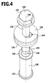
- the shank region 136 of the screw 124 is transferred from the second region 152 of the passage opening 144 of the washer 126 into the first region 146 of the passage opening 144 of the washer 126, by displacing the screw 124 transversely to its longitudinal direction 170.
- This is the in Fig. 4 illustrated state in which the shaft portion 136 of the screw 124 extends through the first portion 146 of the passage opening 144 of the washer 126 therethrough.
- the screw 124 is inserted into the sleeve 128, whose inner diameter D "is greater than the outer diameter D of the threaded portion 134 of the screw 124th
- the washer 126 is pushed with the attached thereto annular member 130 of the sleeve 128 against the screw head 132, and then the washer 126 remote from the lower portion of the interior of the annular member 130 through the screw head side collar 140 of the sleeve 128, overcoming the elastic restoring force of the annular member 130 so that the screw head side collar 140 passes this lower portion of the annular member 130 and into the receptacle 168 of the annular member 130 where it is held by the undercut of the annular member 130, so that the sleeve 128th is locked with the annular member 130 and the washer 126.
- the deformed annular member 130 exerts a compressive pressure on the outer side 160 of the sleeve 128, so that the sleeve 128 is also frictionally connected to the annular member 130 and thus to the washer 126.
- the sleeve 128 is also held coaxially with the central axis 150 of the washer 126 on the same.
- the longitudinal direction 170 of the screw 124 is substantially arranged coaxially with the longitudinal axis of the sleeve 128 and thus to the central axis 150 of the washer 126.
- the sleeve 128 and washer 126 are supported on the first member 102 via the resilient annular member 130 so that the sleeve 128, washer 126, and screw 124 are vibrationally decoupled from the first member 102.
- FIG. 5 and 6 illustrated second embodiment of a combination 122 of a screw 124, a captive held on the screw 124 sleeve 128 and a captive held on the screw 124 washer 126 with fixed thereon annular element 130 differs from the first embodiment described above only in that the transition areas 157, in which the edge 174 of the first portion 146 and the edge 176 of the second portion 152 of the passage opening 144 merge into each other, no - viewed from the central axis 150 of the washer 126 - have convexly curved edges, but instead each have a rim 172, the tangent to the edge 174 of the first region 146 of the passage opening 144 and tangent to the edge 176 of the second region 152 of the passage opening 144 extends.
- the passage opening 144 of the washer 126 therefore does not have a keyhole shape in this second embodiment, as in the first embodiment
- Embodiment but instead the shape of a slot with different radii of curvature at the two ends of the slot.
- the threaded region 134 of the screw 124 can pass through the second region 152 of the passage opening 144 and subsequently the screw 124 can be displaced from the second region 152 into the first region 146 of the passage opening 144, such that the threaded region 134 of the screw 124 does not can get back through the opening 144 more.
Abstract
Description
Die vorliegende Erfindung betrifft eine Kombination aus einer Schraube mit einem Schraubenkopf, einem Gewindebereich und einem zwischen dem Schraubenkopf und dem Gewindebereich angeordneten Schaftbereich, dessen Außendurchmesser kleiner ist als der Außendurchmesser des Gewindebereichs, einer Unterlegscheibe mit einer Durchtrittsöffnung für die Schraube und einer Hülse, deren Innendurchmesser größer ist als der Außendurchmesser des Gewindebereichs der Schraube.The present invention relates to a combination of a screw with a screw head, a threaded portion and arranged between the screw head and the threaded portion shaft portion whose outer diameter is smaller than the outer diameter of the threaded portion, a washer with a passage opening for the screw and a sleeve whose inner diameter greater than the outer diameter of the threaded portion of the screw.
Eine solche Kombination ist aus der
Nach dem Zurückschnappen sind die Unterlegscheibe und die Hülse unverlierbar an der Schraube gehalten.After snapping back, the washer and sleeve are held captive on the screw.
Eine weitere Kombination aus einer Schraube und einer Unterlegscheibe sowie einer Hülse, die unverlierbar an der Schraube gehalten sind, ist aus der
Die
Der vorliegenden Erfindung liegt die Aufgabe zugrunde, eine Kombination der eingangs genannten Art zu schaffen, welche einfach herstellbar ist und dennoch einen sicheren Halt der Hülse und der Unterlegscheibe an der Schraube gewährleistet.The present invention has for its object to provide a combination of the aforementioned type, which is easy to manufacture and yet ensures a secure fit of the sleeve and the washer on the screw.
Diese Aufgabe wird durch eine Kombination nach Anspruch 1 gelöst.This object is achieved by a combination according to claim 1.
Der vorliegenden Erfindung liegt das Konzept zugrunde, den Gewindebereich der Schraube durch den zweiten Bereich der Durchtrittsöffnung der Unterlegscheibe, der einen Durchmesser aufweist, welcher größer ist als der Außendurchmesser des Gewindebereichs der Schraube, hindurchzuführen, bis der Schaftbereich der Schraube im Bereich der Durchtrittsöffnung zu liegen kommt, und dann den Schaftbereich der Schraube von dem zweiten Bereich der Durchtrittsöffnung in den ersten Bereich der Durchtrittsöffnung zu überführen, durch welchen der Gewindebereich der Schraube, dessen Außendurchmesser größer ist als der Durchmesser des ersten Bereichs der Durchtrittsöffnung, nicht mehr zurückbewegt werden kann. Dadurch ist die Unterlegscheibe in einfacher Weise unverlierbar an der Schraube gehalten.The present invention is based on the concept, the threaded portion of the screw through the second portion of the passage opening of the washer having a diameter which is greater than the outer diameter of the threaded portion of the screw to pass until the shank portion of the screw to be in the region of the passage opening comes, and then to transfer the shank portion of the screw from the second region of the passage opening in the first region of the passage opening, through which the threaded portion of the screw whose outer diameter is greater than the diameter of the first portion of the Passage opening, can not be moved back. As a result, the washer is held captive on the screw in a simple manner.
Die Hülse wird ihrerseits dadurch unverlierbar an der Schraube gehalten, dass sie mit der Unterlegscheibe verbunden wird.The sleeve in turn is captive held by the screw that it is connected to the washer.
Die Verbindung zwischen der Hülse und der Unterlegscheibe kann dabei direkt oder indirekt, mit Hilfe eines zusätzlichen Bauelements, das einerseits mit der Hülse und anderseits mit der Unterlegscheibe verbunden ist, erfolgen.The connection between the sleeve and the washer can be done directly or indirectly, with the help of an additional component which is connected on the one hand with the sleeve and on the other hand with the washer.
Da der Gewindebereich der Schraube durch den zweiten Bereich der Durchtrittsöffnung der Unterlegscheibe hindurchbewegt werden kann, ist es nicht erforderlich, eine geschlitzte Unterlegscheibe und/oder eine geschlitzte Hülse zu verwenden; vielmehr können bei der erfindungsgemäßen Kombination eine schlitzfreie Hülse und eine schlitzfreie Unterlegscheibe benutzt werden.Since the threaded portion of the screw can be moved through the second portion of the passage opening of the washer, it is not necessary to use a slotted washer and / or a slotted sleeve; Rather, in the combination according to the invention a slot-free sleeve and a slot-free washer can be used.
Bei einer bevorzugten Ausgestaltung der Erfindung ist vorgesehen, dass der erste Bereich und der zweite Bereich der Durchtrittsöffnung so miteinander in Verbindung stehen, dass die Schraube von dem zweiten Bereich in den ersten Bereich der Durchtrittsöffnung überführbar ist, wenn sich der Schaftbereich der Schraube durch die Durchtrittsöffnung der Unterlegscheibe hindurch erstreckt.In a preferred embodiment of the invention, it is provided that the first region and the second region of the passage opening are connected to one another such that the screw can be transferred from the second region into the first region of the passage opening when the shank region of the screw passes through the passage opening the washer extends therethrough.
Im montierten Zustand der Kombination erstreckt sich der Schaftbereich der Schraube vorzugsweise durch den ersten Bereich der Durchtrittsöffnung der Unterlegscheibe hindurch.In the assembled state of the combination, the shank region of the screw preferably extends through the first region of the passage opening of the washer.
Grundsätzlich können der erste Bereich und der zweite Bereich der Durchtrittsöffnung überlappungsfrei an der Unterlegscheibe vorgesehen und durch einen dazwischen angeordneten Kanal miteinander verbunden sein.In principle, the first region and the second region of the passage opening can be provided without overlapping on the washer and can be connected to one another by a channel arranged therebetween.
Bei einer bevorzugten Ausgestaltung der Erfindung ist jedoch vorgesehen, dass der erste Bereich und der zweite Bereich der Durchtrittsöffnung der Unterlegscheibe einander teilweise überlappen. Durch diese Überlappung wird der insgesamt von der Durchtrittsöffnung der Unterlegscheibe eingenommene Anteil der Unterlegscheibe verringert, so dass die wirksame Fläche der Unterlegscheibe, mit welcher die Unterlegscheibe an dem Schraubenkopf anliegt, möglichst groß gehalten wird.In a preferred embodiment of the invention, however, it is provided that the first region and the second region of the passage opening of the washer partially overlap each other. As a result of this overlapping, the portion of the washer taken in total by the passage opening of the washer is reduced, so that the effective area of the washer with which the washer bears against the screw head is kept as large as possible.
Das Zentrum des ersten Bereichs der Durchtrittsöffnung der Unterlegscheibe ist im wesentlichen mittig an der Unterlegscheibe angeordnet. Dadurch wird erreicht, dass die Schraube im montierten Zustand der Kombination im wesentlichen koaxial zu der Unterlegscheibe angeordnet ist.The center of the first region of the passage opening of the washer is arranged substantially centrally of the washer. This ensures that the screw is arranged in the assembled state of the combination substantially coaxial with the washer.
Das Zentrum des zweiten Bereichs der Durchtrittsöffnung der Unterlegscheibe ist hingegen vorzugsweise relativ zu dem Zentrum des ersten Bereichs der Durchtrittsöffnung der Unterlegscheibe nach außen, d.h. zu dem äußeren Rand der Unterlegscheibe hin, versetzt.The center of the second portion of the passage opening of the washer, however, is preferably relative to the center of the first portion of the passage opening of the washer to the outside, i. towards the outer edge of the washer, offset.
Bei einer Ausgestaltung der erfindungsgemäßen Kombination ist vorgesehen, dass der Rand des ersten Bereichs der Durchtrittsöffnung der Unterlegscheibe und der Rand des zweiten Bereichs der Durchtrittsöffnung der Unterlegscheibe an einem Übergangsbereich ineinander übergehen, wobei der Rand des Übergangsbereichs - von dem Zentrum des ersten Bereichs der Durchtrittsöffnung aus gesehen - konvex gekrümmt ist. Bei dieser Ausgestaltung der Erfindung ergibt sich eine im wesentlichen schlüssellochförmige Durchtrittsöffnung.In one embodiment of the combination according to the invention it is provided that the edge of the first region of the passage opening of the washer and the edge of the second region of the passage opening of the washer at a transition region into each other, wherein the edge of the transition region - from the center of the first region of the passage opening seen - convexly curved. In this embodiment of the invention results in a substantially keyhole-shaped passage opening.
Alternativ hierzu ist bei einer zweiten Ausgestaltung der Erfindung vorgesehen, dass der Rand des ersten Bereichs der Durchtrittsöffnung der Unterlegscheibe und der Rand des zweiten Bereichs der Durchtrittsöffnung der Unterlegscheibe an einem Übergangsbereich ineinander übergehen, wobei der Rand des Übergangsbereichs im wesentlichen tangential zu dem Rand des ersten Bereichs der Durchtrittsöffnung und/oder im wesentlichen tangential zu dem Rand des zweiten Bereichs der Durchtrittsöffnung verläuft. Bei dieser Ausgestaltung kann der Gewindebereich der Schraube besonders einfach durch den zweiten Bereich der Durchtrittsöffnung der Unterlegscheibe hindurchgeführt werden.Alternatively, it is provided in a second embodiment of the invention that the edge of the first region of the passage opening of the washer and the edge of the second region of the passage opening of the washer at a transition region into each other, wherein the edge of the transition region substantially tangential to the edge of the first Area of the passage opening and / or substantially tangential to the edge of the second region of the passage opening extends. In this embodiment, the threaded portion of the screw can be particularly easily passed through the second region of the passage opening of the washer.
Um die Hülse indirekt mit der Unterlegscheibe verbinden zu können, kann vorgesehen sein, dass die Kombination mindestens ein ringförmiges Element umfasst, das an der Unterlegscheibe festgelegt ist und eine Aufnahme für ein schraubenkopfseitiges Ende der Hülse aufweist.In order to connect the sleeve indirectly with the washer, it can be provided that the combination comprises at least one annular element which is fixed to the washer and has a receptacle for a screw head side end of the sleeve.
Das ringförmige Element kann als ein elastisches Element ausgebildet sein, um eine Schwingungsentkopplung der Kombination von den durch die Kombination miteinander zu verbindenden Bauteilen zu erzielen.The annular member may be formed as an elastic member to achieve vibration isolation of the combination of the components to be joined by the combination.
Das ringförmige Element kann insbesondere ein Elastomermaterial umfassen.The annular element may in particular comprise an elastomeric material.
Das schraubenkopfseitige Ende der Hülse kann form- und/oder kraftschlüssig an dem ringförmigen Element gehalten sein.The screw-head-side end of the sleeve can be held positively and / or non-positively on the annular element.
Insbesondere kann vorgesehen sein, dass das schraubenkopfseitige Ende der Hülse mit dem ringförmigen Element verrastet ist.In particular, it can be provided that the screw head end of the sleeve is latched to the annular element.
Das ringförmige Element kann grundsätzlich in beliebiger Weise an der Unterlegscheibe festgelegt sein.The annular element can in principle be fixed in any way on the washer.
Eine besonders haltbare und einfach herzustellende Verbindung des ringförmigen Elements mit der Unterlegscheibe ergibt sich, wenn das ringförmige Element mit der Unterlegscheibe verklebt ist.A particularly durable and easy to make connection of the annular member with the washer results when the annular member is glued to the washer.
Die vorliegende Erfindung betrifft ferner ein Verfahren zum Herstellen einer Kombination aus einer Schraube mit einem Schraubenkopf, einem Gewindebereich und einem zwischen dem Schraubenkopf und dem Gewindebereich angeordneten Schaftbereich, dessen Außendurchmesser kleiner ist als der Außendurchmesser des Gewindebereichs,
einer Unterlegscheibe mit einer Durchtrittsöffnung für die Schraube und einer Hülse, deren Innendurchmesser größer ist als der Außendurchmesser des Gewindebereichs der Schraube.The present invention further relates to a method for producing a combination of a screw with a screw head, a threaded region and a shaft region arranged between the screw head and the threaded region, whose outer diameter is smaller than the outer diameter of the threaded region,
a washer with a passage opening for the screw and a sleeve whose inner diameter is greater than the outer diameter of the threaded portion of the screw.
Der vorliegenden Erfindung liegt die weitere Aufgabe zugrunde, ein Verfahren zum Herstellen einer solchen Kombination zu schaffen, welches einfach durchführbar ist und zu einem sicheren Halt der Hülse und der Unterlegscheibe untereinander und an der Schraube führt.The present invention has the further object of providing a method for producing such a combination, which is easy to carry out and leads to a secure hold of the sleeve and the washer with each other and on the screw.
Diese Aufgabe wird erfindungsgemäß durch ein Verfahren gelöst, das folgende Verfahrensschritte umfasst:
- Bereitstellen einer Unterlegscheibe mit einer Durchtrittsöffnung, die einen ersten Bereich umfasst, welcher einen Durchmesser aufweist, der größer ist als der Außendurchmesser des Schaftbereichs der Schraube und kleiner ist als der Außendurchmesser des Gewindebereichs der Schraube, wobei das Zentrum des ersten Bereichs der Durchgangsöffnung der Unterlegscheibe im wesentlichen mittig an der Unterlegscheibe angeordnet ist, und einen zweiten Bereich, welcher einen Durchmesser aufweist, der größer ist als der Außendurchmesser des Gewindebereichs der Schraube;
- Einstecken der Schraube in die Durchtrittsöffnung der Unterlegscheibe derart, dass der Gewindebereich der Schraube sich durch den zweiten Bereich der Durchtrittsöffnung der Unterlegscheibe hindurchbewegt, bis der Schaftbereich der Schraube sich durch die Durchtrittsöffnung hindurch erstreckt;
- Überführen des Schaftbereichs der Schraube von dem zweiten Bereich der Durchtrittsöffnung der Unterlegscheibe in den ersten Bereich der Durchtrittsöffnung der Unterlegscheibe;
- Einstecken der Schraube in die Hülse;
- Verbinden der Hülse mit der Unterlegscheibe derart, dass die Hülse und die Unterlegscheibe unverlierbar an der Schraube gehalten sind.
- Providing a washer having a passage opening comprising a first portion having a diameter greater than the outer diameter of the shank portion of the screw and smaller than the outer diameter of the threaded portion of the screw, wherein the center of the first portion of the through hole of the washer in essentially centrally located on the washer, and a second portion having a diameter larger than the outer diameter of the threaded portion of the screw;
- Inserting the screw into the passage opening of the washer such that the threaded portion of the screw moves through the second portion of the passage opening of the washer until the shank portion of the screw extends through the passage opening;
- Transferring the shank region of the screw from the second region of the passage opening of the washer into the first region of the passage opening of the washer;
- Inserting the screw into the sleeve;
- Connecting the sleeve with the washer such that the sleeve and the washer are held captive on the screw.
Eine bevorzugte Ausgestaltung dieses Verfahrens umfasst ferner folgendes:
- Festlegen eines ringförmigen Elements an der Unterlegscheibe;
- Verbinden der Hülse mit dem ringförmigen Element derart, dass die Hülse, das ringförmige Element und die Unterlegscheibe unverlierbar an der Schraube gehalten sind.
- Securing an annular member to the washer;
- Connecting the sleeve with the annular member such that the sleeve, the annular member and the washer are held captive on the screw.
Dabei kann das ringförmige Element vor oder nach dem Einstecken der Schraube in die Durchtrittsöffnung der Unterlegscheibe an der Unterlegscheibe festgelegt werden, beispielsweise durch Verklebung.In this case, the annular element can be fixed before or after the insertion of the screw into the passage opening of the washer on the washer, for example by gluing.
Weitere Merkmale und Vorteile der Erfindung sind Gegenstand der nachfolgenden Beschreibung und der zeichnerischen Darstellung von Ausführungsbeispielen.Further features and advantages of the invention are the subject of the following description and the drawings of exemplary embodiments.
In den Zeichnungen zeigen:
- Fig. 1
- einen schematischen Schnitt durch eine Baugruppe aus einem ersten Bauteil und einem zweiten Bauteil, die mittels einer Schraube mit unverlierbar an der Schraube gehaltener Unterleg- scheibe und Hülse sowie mittels Elastomerelementen schwin- gungsentkoppelt aneinander festgelegt sind;
- Fig. 2
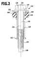
- einen schematischen Längsschnitt durch die Schraube mit Unter- legscheibe, Hülse und Elastomerelement aus
Fig. 1 ; - Fig. 3
- eine Draufsicht von oben auf die Unterlegscheibe aus den
Fig. 1 und2 ; - Fig. 4
- eine schematische perspektivische Darstellung der in die Unter- legscheibe eingesteckten Schraube und der Hülse;
- Fig. 5
- eine Draufsicht von oben auf eine zweite Ausführungsform einer Unterlegscheibe mit einer anders geformten Durchtrittsöffnung; und
- Fig. 6
- eine schematische perspektivische Darstellung des Vorgangs des Einsteckens der Schraube in die Unterlegscheibe.
- Fig. 1
- a schematic section through an assembly of a first component and a second component, which are fixed by means of a screw with captive held on the screw washer and sleeve and by means of elastomer elements vibration-decoupled together;
- Fig. 2
- a schematic longitudinal section through the screw with washer, sleeve and elastomeric element
Fig. 1 ; - Fig. 3
- a top view from above of the washer from the
Fig. 1 and2 ; - Fig. 4
- a schematic perspective view of the screw inserted into the washer and the sleeve;
- Fig. 5
- a top view of a second embodiment of a washer with a different shaped passage opening; and
- Fig. 6
- a schematic perspective view of the process of insertion of the screw in the washer.
Gleiche oder funktional äquivalente Elemente sind in allen Figuren mit denselben Bezugszeichen bezeichnet.Identical or functionally equivalent elements are denoted by the same reference numerals in all figures.
Eine in
Die Schraube 124 umfasst einen Schraubenkopf 132, der beispielsweise als ein Sechskant-Schraubenkopf ausgebildet sein kann, einen Gewindebereich 134 mit einem Außendurchmesser D, einen zwischen dem Gewindebereich 134 und dem Schraubenkopf 132 angeordneten Schaftbereich 136, dessen Außendurchmesser d kleiner ist als der Außendurchmesser D des Gewindebereichs 134, und einen sich an die dem Schraubenkopf 132 abgewandte Seite des Gewindebereichs 134 anschließenden Endbereich 138, dessen Außendurchmesser kleiner ist als der Außendurchmesser D des Gewindebereichs 134 und kleiner ist als der Außendurchmesser d des Schaftbereichs 134 der Schraube 124.The
Die Hülse 128 ist, wie am besten aus den
Wie am besten aus
Der erste, mittig an der Unterlegscheibe 126 angeordnete Bereich 146 der Durchtrittsöffnung 144 weist einen Durchmesser d' auf, welcher größer ist als der Außendurchmesser d des Schaftbereichs 136 der Schraube 124 und kleiner ist als der Außendurchmesser D des Gewindebereichs 134 der Schraube 124.The
Der außermittig an der Unterlegscheibe 126 angeordnete zweite Bereich 152 der Durchtrittsöffnung 144 weist einen Durchmesser D' auf, welcher größer ist als der Außendurchmesser D des Gewindebereichs 134 der Schraube 124.The eccentrically arranged on the
Wie aus
Der kreisbogenabschnittsförmige Rand 174 des ersten Bereichs 146 der Durchtrittsöffrtung 144 und der kreisbogenabschnittsförmige Rand 176 des zweiten Bereichs 152 der Durchtrittsöffnung 144 gehen an zwei Übergangsbereichen 157 ineinander über, wobei die Ränder 172 der Übergangsbereiche 157 - von dem Zentrum 148 des ersten Bereichs 146 der Durchtrittsöffnung 144 aus gesehen - konvex gekrümmt sind (mit einem Krümmungsradius R1).The arcuate portion-shaped
Die Hülse 128, die Unterlegscheibe 126 und die Schraube 124 sind vorzugsweise aus einem metallischen Material, insbesondere aus einem Stahlmaterial, gebildet.The
Das ringförmige Element 130 ist vorzugsweise aus einem elastischen Material, beispielsweise aus einem Elastomermaterial, gebildet.The
Wie am besten aus
Das ringförmige Element 130 ist koaxial zu der Unterlegscheibe 126 angeordnet und an seiner unterlegscheibenseitigen Anlagefläche 162 mit der Unterseite 164 der Unterlegscheibe 126 verklebt.The
Der uriterlegscheibenseitige obere Bereich der Innenseite des ringförmige Elements 130 ist angeschrägt, so dass der von dem ringförmigen Element 130 umgebene Innenraum sich zu der unterlegscheibenseitigen Anlagefläche 162 hin, beispielsweise konisch, erweitert und der unterlegscheibenseitige obere Abschnitt dieses Innenraums eine Aufnahme 168 für den schraubenkopfseitigen Bund 140 der Hülse 128 bildet. Der schräg zur Mittelachse des ringförmigen Elements 130 verlaufende Abschnitt der Innenwand des ringförmigen Elements 130 bildet eine Hinterschneidung, welche den schraubenkopfseitigen Bund 140 der Hülse 128 in der Aufnahme 168 zurückhält, wenn der schraubenkopfseitige Bund 140 in der Aufnahme 168 aufgenommen ist.The uritizing-disk-side upper portion of the inside of the
Um die Kombination 122 aus der Schraube 124, der unverlierbar an der Schraube 124 gehaltenen Unterlegscheibe 126, der unverlierbar an der Schraube 124 gehaltenen Hülse 128 und dem ringförmigen Element 130 herzustellen, wird wie folgt vorgegangen:In order to produce the
Zunächst wird das ringförmige Element 130 mit der Unterlegscheibe 126 verklebt.First, the
Der Innenraum des ringförmigen Elements 130 ist so bemessen, dass es möglich ist, die Schraube 124 mit dem Gewindebereich 134 voran durch den außermittigen zweiten Bereich 152 der Unterlegscheibe 126 hindurchzustecken.The interior of the
Anschließend wird die Schraube 124 derart in die Durchtrittsöffnung 144 der Unterlegscheibe 126 eingesteckt, dass der Gewindebereich 134 der Schraube 124 sich durch den zweiten Bereich 152 der Durchtrittsöffnung 144 der Unterlegscheibe 126 hindurchbewegt, bis der Schaftbereich 136 der Schraube 124 im Bereich der Durchtrittsöffnung 144 zu liegen kommt. Dies ist ohne weiteres möglich, da der zweite Bereich 152 der Durchtrittsöffnung 144 einen Durchmesser D' aufweist, welcher größer ist als der Außendurchmesser D des Gewindebereichs 134 der Schraube 124.Subsequently, the
Anschließend wird der Schaftbereich 136 der Schraube 124 von dem zweiten Bereich 152 der Durchtrittsöffnung 144 der Unterlegscheibe 126 in den ersten Bereich 146 der Durchtrittsöffnung 144 der Unterlegscheibe 126 überführt, indem die Schraube 124 quer zu ihrer Längsrichtung 170 verschoben wird. Damit ist der in
Nun wird die Schraube 124 in die Hülse 128 eingesteckt, deren Innendurchmesser D" größer ist als der Außendurchmesser D des Gewindebereichs 134 der Schraube 124.Now, the
Hierbei wird zunächst die Unterlegscheibe 126 mit dem daran festgelegten ringförmigen Element 130 von der Hülse 128 gegen den Schraubenkopf 132 geschoben, und anschließend wird der der Unterlegscheibe 126 abgewandte untere Abschnitt des Innenraums des ringförmigen Elements 130 durch den schraubenkopfseitigen Bund 140 der Hülse 128 unter Überwindung der elastischen Rückstellkraft des ringförmigen Elements 130 aufgeweitet, so dass der schraubenkopfseitige Bund 140 diesen unteren Abschnitt des ringförmigen Elements 130 passiert und in die Aufnahme 168 des ringförmigen Elements 130 gelangt, wo er durch die Hinterschneidung des ringförmigen Elements 130 festgehalten wird, so dass die Hülse 128 mit dem ringförmigen Element 130 und der Unterlegscheibe 126 verrastet ist.Here, first, the
Außerdem übt das zurückverformte ringförmige Element 130 einen Pressdruck auf die Außenseite 160 der Hülse 128 aus, so dass die Hülse 128 auch durch Reibschluss mit dem ringförmigen Element 130 und somit mit der Unterlegscheibe 126 verbunden ist.In addition, the deformed
Da das ringförmige Element 130 und die Aufnahme 168 koaxial zur Mittelachse 150 der Unterlegscheibe 126 ausgerichtet sind, ist auch die Hülse 128 koaxial zur Mittelachse 150 der Unterlegscheibe 126 an derselben gehalten.Since the
Da sich ferner der untere Endbereich der Hülse 128 bis zu dem Gewindebereich 134 der Schraube 124 erstreckt und der Innendurchmesser D" der Hülse 128 nur geringfügig größer ist als der Außendurchmesser D des Gewindebereichs 134 der Schraube 124, ist die Längsrichtung 170 der Schraube 124 im wesentlichen koaxial zur Längsachse der Hülse 128 und damit zur Mittelachse 150 der Unterlegscheibe 126 angeordnet.Further, since the lower end portion of the
Nach dem Einstecken der Schraube 124 in die Hülse 128 und nach dem Einrasten des schraubenkopfseitigen Bundes 140 der Hülse 128 an dem ringförmigen Element 130 ist es daher nicht mehr möglich, die Schraube 124 aus dem mittigen ersten Bereich 146 der Durchtrittsöffnung 144 der Unterlegscheibe 126 in den außermittigen zweiten Bereich 152 der Durchtrittsöffnung 144 zu verschieben.After the insertion of the
In diesem Zustand kann somit der Gewindebereich 134 der Schraube 124 mit dem Außendurchmesser D nicht mehr durch die Durchtrittsöffnung 144 der Unterlegscheibe 126 zurückgelangen, da der Durchmesser d' des ersten Bereichs 146 der Durchtrittsöffnung 144 kleiner ist als der Außendurchmesser D des Gewindebereichs 134. Die Hülse 128, die Unterlegscheibe 126 und das daran festgelegte ringförmige Element 130 sind somit unverlierbar an der Schraube 124 gehalten.In this state, therefore, the threaded
Im montierten Zustand der Baugruppe 100, wie er in
Die Hülse 128 und die Unterlegscheibe 126 stützen sich über das elastische ringförmige Element 130 an dem ersten Bauteil 102 ab, so dass die Hülse 128, die Unterlegscheibe 126 und die Schraube 124 schwingungsmäßig von dem ersten Bauteil 102 entkoppelt sind.The
Durch das zwischen dem ersten Bauteil 102 und dem zweiten Bauteil 106 angeordnete elastomere Dichtelement 114, das mit seinem Bund 120 den gewindebereichseitigen Bund 142 der Hülse 128 übergreift, wird ferner eine Schwingungsentkopplung zwischen den beiden Bauteilen 102 und 106 erzielt.The
Eine in den
Die Durchtrittsöffnung 144 der Unterlegscheibe 126 hat bei dieser zweiten Ausführungsform daher keine schlüssellochförmige Gestalt, wie bei der erstenThe
Ausführungsform, sondern stattdessen die Form eines Langlochs mit unterschiedlichen Krümmungsradien an den beiden Enden des Langlochs.Embodiment, but instead the shape of a slot with different radii of curvature at the two ends of the slot.
Auch bei dieser Ausführungsform kann der Gewindebereich 134 der Schraube 124 durch den zweiten Bereich 152 der Durchtrittsöffnung 144 hindurchtreten und anschließend die Schraube 124 von dem zweiten Bereich 152 in den ersten Bereich 146 der Durchtrittsöffnung 144 verschoben werden, so dass der Gewindebereich 134 der Schraube 124 nicht mehr durch die Durchtrittsöffnung 144 zurück gelangen kann.In this embodiment too, the threaded
Im übrigen stimmt die in den
Claims (14)
- A combination of a screw member (124) comprising a screw head (132), a threaded portion (134) and a shank portion (136) which is arranged between the screw head (132) and the threaded portion (134) and has an external diameter (d) that is smaller than the external diameter (D) of the threaded portion,
a washer (126) incorporating a passage opening (144) for the screw member (124) and
a sleeve (128) the internal diameter (D") of which is greater than the external diameter (D) of the threaded portion (134) of the screw member (124), wherein the passage opening (144) in the washer (126) comprises a first region (146) having a diameter (d') which is greater than the external diameter (d) of the shank portion (136) of the screw member (124) and is smaller than the external diameter (D) of the threaded portion (134) of the screw member (124), and a second region (152) having a diameter (D') which is greater than the external diameter (D) of the threaded portion (134) of the screw member (124), and
wherein the sleeve (128) and the washer (126) are connected to one another in such a manner that the sleeve (128) and the washer (126) are held captive on the screw member (124),
characterised in that
the centre (148) of the first region (146) of the passage opening (144) in the washer (126) is arranged substantially centrally of the washer (126). - A combination in accordance with Claim 1, characterised in that the first region (146) and the second region (152) of the passage opening (144) are connected to one another in such a way that the screw member (124) can be transferred from the second region (152) into the first region (146) of the passage opening (144) when the shank portion (136) of the screw member (124) extends through the passage opening (144) in the washer (126).
- A combination in accordance with either of Claims 1 or 2, characterised in that in the assembled state of the combination (122), the shank portion (136) of the screw member (124) extends through the first region (146) of the passage opening (144) in the washer (126).
- A combination in accordance with any of Claims 1 to 3, characterised in that the first region (146) and the second region (152) of the passage opening (144) in the washer (126) partly overlap one another.
- A combination in accordance with any of Claims 1 to 4, characterised in that the centre (154) of the second region (152) of the passage opening (144) in the washer (126) is displaced outwardly relative to the centre (148) of the first region (146) of the passage opening (144) in the washer (126).
- A combination in accordance with any of Claims 1 to 5, characterised in that the edge (174) of the first region (146) of the passage opening (144) in the washer (126) and the edge (176) of the second region (152) of the passage opening (144) in the washer (126) merge into one another at a transitional zone (157), whereby - as seen from the centre (148) of the first region (146) of the passage opening (144)- the edge (172) of the transitional zone (157) is curved convexly.
- A combination in accordance with any of Claims 1 to 6, characterised in that the edge (174) of the first region (146) of the passage opening (144) in the washer (126) and the edge (176) of the second region (152) of the passage opening (144) in the washer (126) merge into one another at a transitional zone (157), whereby the edge (172) of the transitional zone (157) runs substantially tangentially to the edge (174) of the first region (146) of the passage opening (144) and/or substantially tangentially to the edge (176) of the second region (152) of the passage opening (144).
- A combination in accordance with any of Claims 1 to 7, characterised in that the combination (122) comprises at least one annular element (130) which is fixed to the washer (126) and has a seating (168) for the screw head end of the sleeve (128).
- A combination in accordance with Claim 8, characterised in that the annular element (130) is in the form of a resilient element.
- A combination in accordance with either of Claims 8 or 9, characterised in that the annular element (130) comprises an elastomer material.
- A combination in accordance with any of Claims 8 to 10, characterised in that the screw head end of the sleeve (128) is held on the annular element (130) in positive and/or force-locking manner.
- A combination in accordance with any of claims 8 to 11, characterised in that the annular element (130) is adhered to the washer (126).
- A method of making a combination (122) consisting of a screw member (124) comprising a screw head (132), a threaded portion (134) and a shank portion (136) which is arranged between the screw head (132) and the threaded portion (134) and has an external diameter (d) that is smaller than the external diameter (D) of the threaded portion (134),
a washer (126) incorporating a passage opening (144) for the screw member (124) and
a sleeve (128) the internal diameter (D") of which is greater than the external diameter (D) of the threaded portion (134) of the screw member (124), comprising the following method steps:- preparing a washer (126) incorporating a passage opening (144) which includes a first region (146) having a diameter (d') that is greater than the external diameter (d) of the shank portion (136) of the screw member (124) and is smaller than the external diameter (D) of the threaded portion (134) of the screw member (124), wherein the centre (148) of the first region (146) of the passage opening (144) of the washer (126) is arranged substantially centrally of the washer (126), anda second region (152) having a diameter (D') which is greater than the external diameter (D) of the threaded portion (134) of the screw member (124);- inserting the screw member (124) into the passage opening (144) in the washer (126) in such a manner that the threaded portion (134) of the screw member (124) moves through the second region (152) of the passage opening (144) in the washer (120) until the shank portion (136) of the screw member (124) extends through the passage opening (144);- transferring the shank portion (136) of the screw member (124) from the second region (152) of the passage opening (144) in the washer (126) into the first region (146) of the passage opening (144) in the washer (126);- inserting the screw member (124) into the sleeve (128);- connecting the sleeve (128) to the washer (126) in such a manner that the sleeve (128) and the washer (126) are held captive on the screw member (124). - A method in accordance with Claim 13, characterised in that the method further comprises the following:- fixing an annular element (130) to the washer (126);- connecting the sleeve (128) to the annular element (130) in such a manner that the sleeve (128), the annular element (130) and the washer (126) are held captive on the screw member (124).
Applications Claiming Priority (1)
| Application Number | Priority Date | Filing Date | Title |
|---|---|---|---|
| PCT/EP2006/010069 WO2008046437A1 (en) | 2006-10-19 | 2006-10-19 | Combination of a screw, a washer, and a sleeve, and method for the production of such a combination |
Publications (2)
| Publication Number | Publication Date |
|---|---|
| EP2082143A1 EP2082143A1 (en) | 2009-07-29 |
| EP2082143B1 true EP2082143B1 (en) | 2010-08-11 |
Family
ID=38016441
Family Applications (1)
| Application Number | Title | Priority Date | Filing Date |
|---|---|---|---|
| EP06806382A Not-in-force EP2082143B1 (en) | 2006-10-19 | 2006-10-19 | Combination of a screw, a washer, and a sleeve, and method for the production of such a combination |
Country Status (5)
| Country | Link |
|---|---|
| US (1) | US7771149B2 (en) |
| EP (1) | EP2082143B1 (en) |
| AT (1) | ATE477425T1 (en) |
| DE (1) | DE502006007669D1 (en) |
| WO (1) | WO2008046437A1 (en) |
Families Citing this family (22)
| Publication number | Priority date | Publication date | Assignee | Title |
|---|---|---|---|---|
| US20100202856A1 (en) * | 2009-02-12 | 2010-08-12 | Acument Intellectual Properties, Llc | Isolator assembly and method of installation |
| US20130071203A1 (en) * | 2011-09-21 | 2013-03-21 | GM Global Technology Operations LLC | Fastener retention system |
| EP2592285A1 (en) * | 2011-11-11 | 2013-05-15 | Volvo Car Corporation | Screw assembly element |
| US11371544B2 (en) | 2011-12-05 | 2022-06-28 | Acument Intellectual Properties, Llc | Fastener with attached compression limiting sleeve |
| US10550876B2 (en) | 2011-12-05 | 2020-02-04 | Acument Intellectual Properties, Llc | Fastener with attached compression limiting sleeve |
| KR101193248B1 (en) * | 2012-06-18 | 2012-10-18 | 동양기전 주식회사 | Bolt assembly for wiper apparatus of a vehicle |
| CA2921147C (en) * | 2012-08-20 | 2018-01-23 | Thomas M. Espinosa | Anchor holders and anchor assemblies for metal decks |
| CN103195788A (en) * | 2013-03-19 | 2013-07-10 | 湖北航天化学技术研究所 | Flat washer |
| JP5880501B2 (en) * | 2013-08-30 | 2016-03-09 | トヨタ自動車株式会社 | Fastening structure of vehicle |
| EP2851552B1 (en) * | 2013-09-18 | 2017-03-01 | Continental Automotive GmbH | Fastening assembly for a fuel rail of a combustion engine |
| DE102014201936A1 (en) * | 2014-02-04 | 2015-08-06 | Volkswagen Aktiengesellschaft | decoupling element |
| EP3380121B1 (en) | 2015-11-23 | 2023-12-20 | Acceleron Pharma Inc. | Actrii antagonist for use in treating eye disorders |
| US9822811B1 (en) | 2016-09-21 | 2017-11-21 | International Business Machines Corporation | Captive externally threaded fastener method |
| US10655664B2 (en) * | 2016-10-04 | 2020-05-19 | Illinois Tool Works Inc. | Fastener assembly having one or more grommets |
| CN107100925B (en) * | 2017-06-05 | 2023-01-03 | 长华控股集团股份有限公司 | Efficient fastener metal flat gasket |
| US10704142B2 (en) * | 2017-07-27 | 2020-07-07 | Applied Materials, Inc. | Quick disconnect resistance temperature detector assembly for rotating pedestal |
| US11267084B1 (en) * | 2019-01-08 | 2022-03-08 | Mitchell S. Olsen | Dipstick adapter leak repair method and kit |
| US11225293B2 (en) * | 2019-01-09 | 2022-01-18 | Deere & Company | Lift apparatus with bearing retainer |
| US11592050B2 (en) | 2019-01-09 | 2023-02-28 | Illinois Tool Works Inc. | Apparatus for a captured fastener assembly with expanding grommet |
| USD952450S1 (en) * | 2020-02-03 | 2022-05-24 | Wheel Pros, Llc | Bolt |
| USD918701S1 (en) * | 2020-02-03 | 2021-05-11 | Wheel Pros, Llc | Bolt |
| USD918700S1 (en) * | 2020-02-03 | 2021-05-11 | Wheel Pros, Llc | Bolt |
Family Cites Families (5)
| Publication number | Priority date | Publication date | Assignee | Title |
|---|---|---|---|---|
| US1937197A (en) * | 1932-08-25 | 1933-11-28 | Calvin L Halladay | Bumper construction and method of making the same |
| US2919736A (en) * | 1957-07-01 | 1960-01-05 | Gen Electric | Threaded fastener retaining device |
| US3343581A (en) * | 1966-07-01 | 1967-09-26 | Northrop Corp | Captive screw fastener |
| US3570836A (en) * | 1968-12-10 | 1971-03-16 | Genevoise Instr Physique | Clamping device for immobilising an object on a support table |
| FR2735818B1 (en) | 1995-06-26 | 1997-07-18 | Valeo Systemes Dessuyage | DEVICE FOR FIXING AN ELEMENT BELONGING TO A WINDSCREEN WIPER MECHANISM ON THE BODY OF A MOTOR VEHICLE |
-
2006
- 2006-10-19 AT AT06806382T patent/ATE477425T1/en active
- 2006-10-19 WO PCT/EP2006/010069 patent/WO2008046437A1/en active Application Filing
- 2006-10-19 DE DE502006007669T patent/DE502006007669D1/en active Active
- 2006-10-19 EP EP06806382A patent/EP2082143B1/en not_active Not-in-force
-
2007
- 2007-10-09 US US11/973,511 patent/US7771149B2/en not_active Expired - Fee Related
Also Published As
| Publication number | Publication date |
|---|---|
| WO2008046437A8 (en) | 2008-07-17 |
| US20080152458A1 (en) | 2008-06-26 |
| WO2008046437A1 (en) | 2008-04-24 |
| ATE477425T1 (en) | 2010-08-15 |
| DE502006007669D1 (en) | 2010-09-23 |
| US7771149B2 (en) | 2010-08-10 |
| EP2082143A1 (en) | 2009-07-29 |
Similar Documents
| Publication | Publication Date | Title |
|---|---|---|
| EP2082143B1 (en) | Combination of a screw, a washer, and a sleeve, and method for the production of such a combination | |
| EP2047125B1 (en) | Sleeve | |
| EP1068458B1 (en) | Joining device for joining two structural parts, the combination of the joining device with the two structural parts and method for producing a joint between two structural parts | |
| EP2318723B1 (en) | Fastening arrangement with tolerance compensation | |
| EP2047127B1 (en) | Combination of a screw, a washer and a sleeve and method for producing said combination | |
| EP0487890B1 (en) | Member joint, especially flanged joint | |
| EP3698056B1 (en) | Tolerance compensation assembly | |
| EP3698055A1 (en) | Tolerance compensation assembly | |
| DE102019113663B4 (en) | SPACER FOR A FIXING ASSEMBLY, FIXING ASSEMBLY WITH SUCH SPACER, AND METHOD FOR ATTACHING A MOUNTING PART TO A SUPPORT PART | |
| EP3036443B1 (en) | Method for joining components, and an assembly | |
| EP3717786A1 (en) | Tolerance compensation arrangement with safety clamp | |
| EP4095396B1 (en) | Tolerance compensating device | |
| EP2082144A1 (en) | Combination of a screw and a sleeve, and method for producing a combination of this type | |
| EP2484924A1 (en) | Joint connection and method for forming a joint connection | |
| DE10351716A1 (en) | Cylinder head gasket for IC engine with at least one positioning and/or fixing bolt secured in reception bore by retaining teeth engaging front and rear sides of bore edge | |
| EP0534001B1 (en) | Screwed connections for connecting two structural members at some distance, in particular sheets | |
| EP1612432B1 (en) | Fastening assembly for a trim panel and fastening method | |
| DE102013208494A1 (en) | Device for toolless connection of components i.e. furnitures, in furniture industry, has outer flange whose front end comprising recess for holding of other outer flange, and connection pin provided for introduction into hollow dowels | |
| DE10020218B4 (en) | Assembly unit of a component and at least one thread-forming screw | |
| DE10254999B4 (en) | assembly unit | |
| EP3736464B1 (en) | Spacer for a fastening arrangement, fastening arrangement with such a spacer and method for fastening an assembly part to a support part | |
| EP2667043A1 (en) | Blind rivet element | |
| EP3988803B1 (en) | Functional unit with connecting element and fixing element | |
| WO2005085662A1 (en) | Holder for tubular parts | |
| EP3268556B1 (en) | Fastening element and fastening system for fastening composite plates, in particular for façade elements |
Legal Events
| Date | Code | Title | Description |
|---|---|---|---|
| PUAI | Public reference made under article 153(3) epc to a published international application that has entered the european phase |
Free format text: ORIGINAL CODE: 0009012 |
|
| 17P | Request for examination filed |
Effective date: 20090409 |
|
| AK | Designated contracting states |
Kind code of ref document: A1 Designated state(s): AT BE BG CH CY CZ DE DK EE ES FI FR GB GR HU IE IS IT LI LT LU LV MC NL PL PT RO SE SI SK TR |
|
| DAX | Request for extension of the european patent (deleted) | ||
| GRAP | Despatch of communication of intention to grant a patent |
Free format text: ORIGINAL CODE: EPIDOSNIGR1 |
|
| GRAS | Grant fee paid |
Free format text: ORIGINAL CODE: EPIDOSNIGR3 |
|
| GRAA | (expected) grant |
Free format text: ORIGINAL CODE: 0009210 |
|
| AK | Designated contracting states |
Kind code of ref document: B1 Designated state(s): AT BE BG CH CY CZ DE DK EE ES FI FR GB GR HU IE IS IT LI LT LU LV MC NL PL PT RO SE SI SK TR |
|
| REG | Reference to a national code |
Ref country code: GB Ref legal event code: FG4D Free format text: NOT ENGLISH |
|
| REG | Reference to a national code |
Ref country code: CH Ref legal event code: EP |
|
| REG | Reference to a national code |
Ref country code: IE Ref legal event code: FG4D Free format text: LANGUAGE OF EP DOCUMENT: GERMAN |
|
| REF | Corresponds to: |
Ref document number: 502006007669 Country of ref document: DE Date of ref document: 20100923 Kind code of ref document: P |
|
| REG | Reference to a national code |
Ref country code: NL Ref legal event code: VDEP Effective date: 20100811 |
|
| LTIE | Lt: invalidation of european patent or patent extension |
Effective date: 20100811 |
|
| PG25 | Lapsed in a contracting state [announced via postgrant information from national office to epo] |
Ref country code: FI Free format text: LAPSE BECAUSE OF FAILURE TO SUBMIT A TRANSLATION OF THE DESCRIPTION OR TO PAY THE FEE WITHIN THE PRESCRIBED TIME-LIMIT Effective date: 20100811 Ref country code: NL Free format text: LAPSE BECAUSE OF FAILURE TO SUBMIT A TRANSLATION OF THE DESCRIPTION OR TO PAY THE FEE WITHIN THE PRESCRIBED TIME-LIMIT Effective date: 20100811 Ref country code: LT Free format text: LAPSE BECAUSE OF FAILURE TO SUBMIT A TRANSLATION OF THE DESCRIPTION OR TO PAY THE FEE WITHIN THE PRESCRIBED TIME-LIMIT Effective date: 20100811 |
|
| PG25 | Lapsed in a contracting state [announced via postgrant information from national office to epo] |
Ref country code: IS Free format text: LAPSE BECAUSE OF FAILURE TO SUBMIT A TRANSLATION OF THE DESCRIPTION OR TO PAY THE FEE WITHIN THE PRESCRIBED TIME-LIMIT Effective date: 20101211 Ref country code: BG Free format text: LAPSE BECAUSE OF FAILURE TO SUBMIT A TRANSLATION OF THE DESCRIPTION OR TO PAY THE FEE WITHIN THE PRESCRIBED TIME-LIMIT Effective date: 20101111 Ref country code: CY Free format text: LAPSE BECAUSE OF FAILURE TO SUBMIT A TRANSLATION OF THE DESCRIPTION OR TO PAY THE FEE WITHIN THE PRESCRIBED TIME-LIMIT Effective date: 20100811 Ref country code: SI Free format text: LAPSE BECAUSE OF FAILURE TO SUBMIT A TRANSLATION OF THE DESCRIPTION OR TO PAY THE FEE WITHIN THE PRESCRIBED TIME-LIMIT Effective date: 20100811 Ref country code: PT Free format text: LAPSE BECAUSE OF FAILURE TO SUBMIT A TRANSLATION OF THE DESCRIPTION OR TO PAY THE FEE WITHIN THE PRESCRIBED TIME-LIMIT Effective date: 20101213 Ref country code: PL Free format text: LAPSE BECAUSE OF FAILURE TO SUBMIT A TRANSLATION OF THE DESCRIPTION OR TO PAY THE FEE WITHIN THE PRESCRIBED TIME-LIMIT Effective date: 20100811 |
|
| REG | Reference to a national code |
Ref country code: IE Ref legal event code: FD4D |
|
| PG25 | Lapsed in a contracting state [announced via postgrant information from national office to epo] |
Ref country code: LV Free format text: LAPSE BECAUSE OF FAILURE TO SUBMIT A TRANSLATION OF THE DESCRIPTION OR TO PAY THE FEE WITHIN THE PRESCRIBED TIME-LIMIT Effective date: 20100811 Ref country code: GR Free format text: LAPSE BECAUSE OF FAILURE TO SUBMIT A TRANSLATION OF THE DESCRIPTION OR TO PAY THE FEE WITHIN THE PRESCRIBED TIME-LIMIT Effective date: 20101112 Ref country code: SE Free format text: LAPSE BECAUSE OF FAILURE TO SUBMIT A TRANSLATION OF THE DESCRIPTION OR TO PAY THE FEE WITHIN THE PRESCRIBED TIME-LIMIT Effective date: 20100811 |
|
| PG25 | Lapsed in a contracting state [announced via postgrant information from national office to epo] |
Ref country code: IE Free format text: LAPSE BECAUSE OF FAILURE TO SUBMIT A TRANSLATION OF THE DESCRIPTION OR TO PAY THE FEE WITHIN THE PRESCRIBED TIME-LIMIT Effective date: 20100811 Ref country code: DK Free format text: LAPSE BECAUSE OF FAILURE TO SUBMIT A TRANSLATION OF THE DESCRIPTION OR TO PAY THE FEE WITHIN THE PRESCRIBED TIME-LIMIT Effective date: 20100811 |
|
| BERE | Be: lapsed |
Owner name: ELRINGKLINGER A.G. Effective date: 20101031 |
|
| PG25 | Lapsed in a contracting state [announced via postgrant information from national office to epo] |
Ref country code: RO Free format text: LAPSE BECAUSE OF FAILURE TO SUBMIT A TRANSLATION OF THE DESCRIPTION OR TO PAY THE FEE WITHIN THE PRESCRIBED TIME-LIMIT Effective date: 20100811 Ref country code: CZ Free format text: LAPSE BECAUSE OF FAILURE TO SUBMIT A TRANSLATION OF THE DESCRIPTION OR TO PAY THE FEE WITHIN THE PRESCRIBED TIME-LIMIT Effective date: 20100811 Ref country code: MC Free format text: LAPSE BECAUSE OF NON-PAYMENT OF DUE FEES Effective date: 20101031 Ref country code: EE Free format text: LAPSE BECAUSE OF FAILURE TO SUBMIT A TRANSLATION OF THE DESCRIPTION OR TO PAY THE FEE WITHIN THE PRESCRIBED TIME-LIMIT Effective date: 20100811 Ref country code: SK Free format text: LAPSE BECAUSE OF FAILURE TO SUBMIT A TRANSLATION OF THE DESCRIPTION OR TO PAY THE FEE WITHIN THE PRESCRIBED TIME-LIMIT Effective date: 20100811 Ref country code: IT Free format text: LAPSE BECAUSE OF FAILURE TO SUBMIT A TRANSLATION OF THE DESCRIPTION OR TO PAY THE FEE WITHIN THE PRESCRIBED TIME-LIMIT Effective date: 20100811 |
|
| REG | Reference to a national code |
Ref country code: CH Ref legal event code: PL |
|
| PLBE | No opposition filed within time limit |
Free format text: ORIGINAL CODE: 0009261 |
|
| STAA | Information on the status of an ep patent application or granted ep patent |
Free format text: STATUS: NO OPPOSITION FILED WITHIN TIME LIMIT |
|
| PG25 | Lapsed in a contracting state [announced via postgrant information from national office to epo] |
Ref country code: ES Free format text: LAPSE BECAUSE OF FAILURE TO SUBMIT A TRANSLATION OF THE DESCRIPTION OR TO PAY THE FEE WITHIN THE PRESCRIBED TIME-LIMIT Effective date: 20101122 |
|
| 26N | No opposition filed |
Effective date: 20110512 |
|
| GBPC | Gb: european patent ceased through non-payment of renewal fee |
Effective date: 20101111 |
|
| PG25 | Lapsed in a contracting state [announced via postgrant information from national office to epo] |
Ref country code: LI Free format text: LAPSE BECAUSE OF NON-PAYMENT OF DUE FEES Effective date: 20101031 Ref country code: CH Free format text: LAPSE BECAUSE OF NON-PAYMENT OF DUE FEES Effective date: 20101031 |
|
| PG25 | Lapsed in a contracting state [announced via postgrant information from national office to epo] |
Ref country code: BE Free format text: LAPSE BECAUSE OF NON-PAYMENT OF DUE FEES Effective date: 20101031 |
|
| REG | Reference to a national code |
Ref country code: DE Ref legal event code: R097 Ref document number: 502006007669 Country of ref document: DE Effective date: 20110512 |
|
| PG25 | Lapsed in a contracting state [announced via postgrant information from national office to epo] |
Ref country code: GB Free format text: LAPSE BECAUSE OF NON-PAYMENT OF DUE FEES Effective date: 20101111 |
|
| PG25 | Lapsed in a contracting state [announced via postgrant information from national office to epo] |
Ref country code: HU Free format text: LAPSE BECAUSE OF FAILURE TO SUBMIT A TRANSLATION OF THE DESCRIPTION OR TO PAY THE FEE WITHIN THE PRESCRIBED TIME-LIMIT Effective date: 20110212 Ref country code: LU Free format text: LAPSE BECAUSE OF NON-PAYMENT OF DUE FEES Effective date: 20101019 |
|
| PG25 | Lapsed in a contracting state [announced via postgrant information from national office to epo] |
Ref country code: TR Free format text: LAPSE BECAUSE OF FAILURE TO SUBMIT A TRANSLATION OF THE DESCRIPTION OR TO PAY THE FEE WITHIN THE PRESCRIBED TIME-LIMIT Effective date: 20100811 |
|
| REG | Reference to a national code |
Ref country code: AT Ref legal event code: MM01 Ref document number: 477425 Country of ref document: AT Kind code of ref document: T Effective date: 20111019 |
|
| PG25 | Lapsed in a contracting state [announced via postgrant information from national office to epo] |
Ref country code: AT Free format text: LAPSE BECAUSE OF NON-PAYMENT OF DUE FEES Effective date: 20111019 |
|
| REG | Reference to a national code |
Ref country code: DE Ref legal event code: R082 Ref document number: 502006007669 Country of ref document: DE Representative=s name: HOEGER, STELLRECHT & PARTNER PATENTANWAELTE MB, DE |
|
| REG | Reference to a national code |
Ref country code: FR Ref legal event code: PLFP Year of fee payment: 10 |
|
| PGFP | Annual fee paid to national office [announced via postgrant information from national office to epo] |
Ref country code: DE Payment date: 20151022 Year of fee payment: 10 |
|
| PGFP | Annual fee paid to national office [announced via postgrant information from national office to epo] |
Ref country code: FR Payment date: 20151026 Year of fee payment: 10 |
|
| REG | Reference to a national code |
Ref country code: DE Ref legal event code: R119 Ref document number: 502006007669 Country of ref document: DE |
|
| REG | Reference to a national code |
Ref country code: FR Ref legal event code: ST Effective date: 20170630 |
|
| PG25 | Lapsed in a contracting state [announced via postgrant information from national office to epo] |
Ref country code: FR Free format text: LAPSE BECAUSE OF NON-PAYMENT OF DUE FEES Effective date: 20161102 Ref country code: DE Free format text: LAPSE BECAUSE OF NON-PAYMENT OF DUE FEES Effective date: 20170503 |