EP2081239A2 - Superconductive wire, processes of manufacture and uses thereof - Google Patents
Superconductive wire, processes of manufacture and uses thereof Download PDFInfo
- Publication number
- EP2081239A2 EP2081239A2 EP09150108A EP09150108A EP2081239A2 EP 2081239 A2 EP2081239 A2 EP 2081239A2 EP 09150108 A EP09150108 A EP 09150108A EP 09150108 A EP09150108 A EP 09150108A EP 2081239 A2 EP2081239 A2 EP 2081239A2
- Authority
- EP
- European Patent Office
- Prior art keywords
- wire
- tolerance
- superconductive
- magnetic field
- wire segment
- Prior art date
- Legal status (The legal status is an assumption and is not a legal conclusion. Google has not performed a legal analysis and makes no representation as to the accuracy of the status listed.)
- Granted
Links
- 238000000034 method Methods 0.000 title claims description 34
- 230000008569 process Effects 0.000 title claims description 26
- 238000004519 manufacturing process Methods 0.000 title description 12
- 230000005291 magnetic effect Effects 0.000 claims abstract description 88
- 230000015556 catabolic process Effects 0.000 claims abstract description 14
- 238000006731 degradation reaction Methods 0.000 claims abstract description 14
- 239000000203 mixture Substances 0.000 claims description 45
- 238000004804 winding Methods 0.000 claims description 30
- 238000005304 joining Methods 0.000 claims description 16
- 229910000657 niobium-tin Inorganic materials 0.000 claims description 14
- 229910021521 yttrium barium copper oxide Inorganic materials 0.000 claims description 6
- 229910020073 MgB2 Inorganic materials 0.000 claims description 5
- 229910052751 metal Inorganic materials 0.000 description 22
- 239000002184 metal Substances 0.000 description 22
- 239000011159 matrix material Substances 0.000 description 16
- 239000002019 doping agent Substances 0.000 description 15
- 239000010949 copper Substances 0.000 description 14
- 239000000463 material Substances 0.000 description 12
- 238000010438 heat treatment Methods 0.000 description 9
- 239000012071 phase Substances 0.000 description 9
- RYGMFSIKBFXOCR-UHFFFAOYSA-N Copper Chemical compound [Cu] RYGMFSIKBFXOCR-UHFFFAOYSA-N 0.000 description 8
- XEEYBQQBJWHFJM-UHFFFAOYSA-N Iron Chemical compound [Fe] XEEYBQQBJWHFJM-UHFFFAOYSA-N 0.000 description 8
- 229910052802 copper Inorganic materials 0.000 description 7
- 238000009792 diffusion process Methods 0.000 description 7
- 238000003466 welding Methods 0.000 description 7
- FYYHWMGAXLPEAU-UHFFFAOYSA-N Magnesium Chemical compound [Mg] FYYHWMGAXLPEAU-UHFFFAOYSA-N 0.000 description 6
- 229910052749 magnesium Inorganic materials 0.000 description 6
- 239000011777 magnesium Substances 0.000 description 6
- 230000004907 flux Effects 0.000 description 5
- 239000002245 particle Substances 0.000 description 5
- 229910000881 Cu alloy Inorganic materials 0.000 description 4
- 230000005294 ferromagnetic effect Effects 0.000 description 4
- 239000000945 filler Substances 0.000 description 4
- 229910052742 iron Inorganic materials 0.000 description 4
- 229910052718 tin Inorganic materials 0.000 description 4
- 239000011135 tin Substances 0.000 description 4
- 230000007704 transition Effects 0.000 description 4
- GYHNNYVSQQEPJS-UHFFFAOYSA-N Gallium Chemical compound [Ga] GYHNNYVSQQEPJS-UHFFFAOYSA-N 0.000 description 3
- BQCADISMDOOEFD-UHFFFAOYSA-N Silver Chemical compound [Ag] BQCADISMDOOEFD-UHFFFAOYSA-N 0.000 description 3
- ATJFFYVFTNAWJD-UHFFFAOYSA-N Tin Chemical compound [Sn] ATJFFYVFTNAWJD-UHFFFAOYSA-N 0.000 description 3
- HCHKCACWOHOZIP-UHFFFAOYSA-N Zinc Chemical compound [Zn] HCHKCACWOHOZIP-UHFFFAOYSA-N 0.000 description 3
- 230000008901 benefit Effects 0.000 description 3
- 229910052797 bismuth Inorganic materials 0.000 description 3
- JCXGWMGPZLAOME-UHFFFAOYSA-N bismuth atom Chemical compound [Bi] JCXGWMGPZLAOME-UHFFFAOYSA-N 0.000 description 3
- 229910052793 cadmium Inorganic materials 0.000 description 3
- BDOSMKKIYDKNTQ-UHFFFAOYSA-N cadmium atom Chemical compound [Cd] BDOSMKKIYDKNTQ-UHFFFAOYSA-N 0.000 description 3
- 230000008878 coupling Effects 0.000 description 3
- 238000010168 coupling process Methods 0.000 description 3
- 238000005859 coupling reaction Methods 0.000 description 3
- 239000012530 fluid Substances 0.000 description 3
- 229910052733 gallium Inorganic materials 0.000 description 3
- PCHJSUWPFVWCPO-UHFFFAOYSA-N gold Chemical compound [Au] PCHJSUWPFVWCPO-UHFFFAOYSA-N 0.000 description 3
- 229910052737 gold Inorganic materials 0.000 description 3
- 239000010931 gold Substances 0.000 description 3
- 229910052738 indium Inorganic materials 0.000 description 3
- APFVFJFRJDLVQX-UHFFFAOYSA-N indium atom Chemical compound [In] APFVFJFRJDLVQX-UHFFFAOYSA-N 0.000 description 3
- 239000011133 lead Substances 0.000 description 3
- QSHDDOUJBYECFT-UHFFFAOYSA-N mercury Chemical compound [Hg] QSHDDOUJBYECFT-UHFFFAOYSA-N 0.000 description 3
- 229910052753 mercury Inorganic materials 0.000 description 3
- 239000000843 powder Substances 0.000 description 3
- 229910052709 silver Inorganic materials 0.000 description 3
- 239000004332 silver Substances 0.000 description 3
- 229910052725 zinc Inorganic materials 0.000 description 3
- 239000011701 zinc Substances 0.000 description 3
- CSCPPACGZOOCGX-UHFFFAOYSA-N Acetone Chemical compound CC(C)=O CSCPPACGZOOCGX-UHFFFAOYSA-N 0.000 description 2
- 229910000990 Ni alloy Inorganic materials 0.000 description 2
- PXHVJJICTQNCMI-UHFFFAOYSA-N Nickel Chemical compound [Ni] PXHVJJICTQNCMI-UHFFFAOYSA-N 0.000 description 2
- 230000004888 barrier function Effects 0.000 description 2
- 230000008859 change Effects 0.000 description 2
- 238000006243 chemical reaction Methods 0.000 description 2
- 238000004891 communication Methods 0.000 description 2
- 239000012809 cooling fluid Substances 0.000 description 2
- 238000010894 electron beam technology Methods 0.000 description 2
- 239000003302 ferromagnetic material Substances 0.000 description 2
- 230000006870 function Effects 0.000 description 2
- 239000007788 liquid Substances 0.000 description 2
- 229910052758 niobium Inorganic materials 0.000 description 2
- 239000010955 niobium Substances 0.000 description 2
- 239000008188 pellet Substances 0.000 description 2
- 239000002904 solvent Substances 0.000 description 2
- 229910001220 stainless steel Inorganic materials 0.000 description 2
- 239000010935 stainless steel Substances 0.000 description 2
- 239000002887 superconductor Substances 0.000 description 2
- 229910052715 tantalum Inorganic materials 0.000 description 2
- GUVRBAGPIYLISA-UHFFFAOYSA-N tantalum atom Chemical group [Ta] GUVRBAGPIYLISA-UHFFFAOYSA-N 0.000 description 2
- IJGRMHOSHXDMSA-UHFFFAOYSA-N Atomic nitrogen Chemical compound N#N IJGRMHOSHXDMSA-UHFFFAOYSA-N 0.000 description 1
- ZOXJGFHDIHLPTG-UHFFFAOYSA-N Boron Chemical compound [B] ZOXJGFHDIHLPTG-UHFFFAOYSA-N 0.000 description 1
- ZOKXTWBITQBERF-UHFFFAOYSA-N Molybdenum Chemical compound [Mo] ZOKXTWBITQBERF-UHFFFAOYSA-N 0.000 description 1
- 229910001093 Zr alloy Inorganic materials 0.000 description 1
- OSOKRZIXBNTTJX-UHFFFAOYSA-N [O].[Ca].[Cu].[Sr].[Bi] Chemical class [O].[Ca].[Cu].[Sr].[Bi] OSOKRZIXBNTTJX-UHFFFAOYSA-N 0.000 description 1
- 238000005299 abrasion Methods 0.000 description 1
- 230000002411 adverse Effects 0.000 description 1
- 230000015572 biosynthetic process Effects 0.000 description 1
- 229910052796 boron Inorganic materials 0.000 description 1
- 238000003486 chemical etching Methods 0.000 description 1
- 230000003749 cleanliness Effects 0.000 description 1
- 229910017052 cobalt Inorganic materials 0.000 description 1
- 239000010941 cobalt Substances 0.000 description 1
- GUTLYIVDDKVIGB-UHFFFAOYSA-N cobalt atom Chemical group [Co] GUTLYIVDDKVIGB-UHFFFAOYSA-N 0.000 description 1
- 239000012141 concentrate Substances 0.000 description 1
- 238000010276 construction Methods 0.000 description 1
- 238000001816 cooling Methods 0.000 description 1
- 230000001351 cycling effect Effects 0.000 description 1
- 230000003247 decreasing effect Effects 0.000 description 1
- 230000000694 effects Effects 0.000 description 1
- 230000005611 electricity Effects 0.000 description 1
- 238000001125 extrusion Methods 0.000 description 1
- 238000005242 forging Methods 0.000 description 1
- 238000000227 grinding Methods 0.000 description 1
- 239000001307 helium Substances 0.000 description 1
- 229910052734 helium Inorganic materials 0.000 description 1
- SWQJXJOGLNCZEY-UHFFFAOYSA-N helium atom Chemical compound [He] SWQJXJOGLNCZEY-UHFFFAOYSA-N 0.000 description 1
- 230000003993 interaction Effects 0.000 description 1
- 150000002505 iron Chemical class 0.000 description 1
- WPBNNNQJVZRUHP-UHFFFAOYSA-L manganese(2+);methyl n-[[2-(methoxycarbonylcarbamothioylamino)phenyl]carbamothioyl]carbamate;n-[2-(sulfidocarbothioylamino)ethyl]carbamodithioate Chemical compound [Mn+2].[S-]C(=S)NCCNC([S-])=S.COC(=O)NC(=S)NC1=CC=CC=C1NC(=S)NC(=O)OC WPBNNNQJVZRUHP-UHFFFAOYSA-L 0.000 description 1
- 238000002844 melting Methods 0.000 description 1
- 230000008018 melting Effects 0.000 description 1
- 150000002739 metals Chemical class 0.000 description 1
- 230000005012 migration Effects 0.000 description 1
- 238000013508 migration Methods 0.000 description 1
- 229910052750 molybdenum Inorganic materials 0.000 description 1
- 239000011733 molybdenum Substances 0.000 description 1
- 229910052754 neon Inorganic materials 0.000 description 1
- GKAOGPIIYCISHV-UHFFFAOYSA-N neon atom Chemical compound [Ne] GKAOGPIIYCISHV-UHFFFAOYSA-N 0.000 description 1
- 229910052759 nickel Inorganic materials 0.000 description 1
- 229910001000 nickel titanium Inorganic materials 0.000 description 1
- ZSJFLDUTBDIFLJ-UHFFFAOYSA-N nickel zirconium Chemical compound [Ni].[Zr] ZSJFLDUTBDIFLJ-UHFFFAOYSA-N 0.000 description 1
- GUCVJGMIXFAOAE-UHFFFAOYSA-N niobium atom Chemical compound [Nb] GUCVJGMIXFAOAE-UHFFFAOYSA-N 0.000 description 1
- 230000003647 oxidation Effects 0.000 description 1
- 238000007254 oxidation reaction Methods 0.000 description 1
- 229910001175 oxide dispersion-strengthened alloy Inorganic materials 0.000 description 1
- 238000005498 polishing Methods 0.000 description 1
- 239000002243 precursor Substances 0.000 description 1
- 230000009467 reduction Effects 0.000 description 1
- 238000005096 rolling process Methods 0.000 description 1
- 239000007790 solid phase Substances 0.000 description 1
- 239000000126 substance Substances 0.000 description 1
- 239000000758 substrate Substances 0.000 description 1
- 230000003746 surface roughness Effects 0.000 description 1
- 238000007669 thermal treatment Methods 0.000 description 1
- 229910052719 titanium Inorganic materials 0.000 description 1
- 239000010936 titanium Substances 0.000 description 1
- WFKWXMTUELFFGS-UHFFFAOYSA-N tungsten Chemical compound [W] WFKWXMTUELFFGS-UHFFFAOYSA-N 0.000 description 1
- 229910052721 tungsten Inorganic materials 0.000 description 1
- 239000010937 tungsten Substances 0.000 description 1
Images


Classifications
-
- H—ELECTRICITY
- H10—SEMICONDUCTOR DEVICES; ELECTRIC SOLID-STATE DEVICES NOT OTHERWISE PROVIDED FOR
- H10N—ELECTRIC SOLID-STATE DEVICES NOT OTHERWISE PROVIDED FOR
- H10N60/00—Superconducting devices
- H10N60/20—Permanent superconducting devices
-
- H—ELECTRICITY
- H01—ELECTRIC ELEMENTS
- H01F—MAGNETS; INDUCTANCES; TRANSFORMERS; SELECTION OF MATERIALS FOR THEIR MAGNETIC PROPERTIES
- H01F6/00—Superconducting magnets; Superconducting coils
- H01F6/06—Coils, e.g. winding, insulating, terminating or casing arrangements therefor
-
- H—ELECTRICITY
- H02—GENERATION; CONVERSION OR DISTRIBUTION OF ELECTRIC POWER
- H02K—DYNAMO-ELECTRIC MACHINES
- H02K55/00—Dynamo-electric machines having windings operating at cryogenic temperatures
-
- H—ELECTRICITY
- H10—SEMICONDUCTOR DEVICES; ELECTRIC SOLID-STATE DEVICES NOT OTHERWISE PROVIDED FOR
- H10N—ELECTRIC SOLID-STATE DEVICES NOT OTHERWISE PROVIDED FOR
- H10N60/00—Superconducting devices
- H10N60/80—Constructional details
-
- Y—GENERAL TAGGING OF NEW TECHNOLOGICAL DEVELOPMENTS; GENERAL TAGGING OF CROSS-SECTIONAL TECHNOLOGIES SPANNING OVER SEVERAL SECTIONS OF THE IPC; TECHNICAL SUBJECTS COVERED BY FORMER USPC CROSS-REFERENCE ART COLLECTIONS [XRACs] AND DIGESTS
- Y02—TECHNOLOGIES OR APPLICATIONS FOR MITIGATION OR ADAPTATION AGAINST CLIMATE CHANGE
- Y02E—REDUCTION OF GREENHOUSE GAS [GHG] EMISSIONS, RELATED TO ENERGY GENERATION, TRANSMISSION OR DISTRIBUTION
- Y02E10/00—Energy generation through renewable energy sources
- Y02E10/70—Wind energy
- Y02E10/72—Wind turbines with rotation axis in wind direction
-
- Y—GENERAL TAGGING OF NEW TECHNOLOGICAL DEVELOPMENTS; GENERAL TAGGING OF CROSS-SECTIONAL TECHNOLOGIES SPANNING OVER SEVERAL SECTIONS OF THE IPC; TECHNICAL SUBJECTS COVERED BY FORMER USPC CROSS-REFERENCE ART COLLECTIONS [XRACs] AND DIGESTS
- Y02—TECHNOLOGIES OR APPLICATIONS FOR MITIGATION OR ADAPTATION AGAINST CLIMATE CHANGE
- Y02E—REDUCTION OF GREENHOUSE GAS [GHG] EMISSIONS, RELATED TO ENERGY GENERATION, TRANSMISSION OR DISTRIBUTION
- Y02E40/00—Technologies for an efficient electrical power generation, transmission or distribution
- Y02E40/60—Superconducting electric elements or equipment; Power systems integrating superconducting elements or equipment
Definitions
- the present disclosure relates generally to superconductive wire, methods of manufacture, and uses thereof in electronic components.
- Typical superconductive (SC) rotating machines such as electrical motors and generators comprise a SC field coil and non-superconductive armature windings located, for example, on a stationary stator.
- SC superconductive
- the field coil When supplied a voltage, the field coil generates a magnetic field coupling the field coil and the armature windings.
- the magnitude of the coupling magnetic field is determined by the amount of current passed through the field coil and to a lesser extent by the armature reaction current from the load.
- the magnetic stress within the machine translates to torque resulting in rotation of the rotor.
- the higher the magnetic field the greater the torque per rotation for a given circumference of armature windings and air gap surface area.
- the armature windings can also be superconductive, they are usually formed of non-SC material such as copper.
- SC wires such as NbTi or Nb 3 Sn
- the current carrying capacity is a function of the critical current Ic, the current where the material has a phase transition from a superconductive phase to a non-superconductive phase.
- Ic is a decreasing function of temperature T and magnetic field H.
- SC wires also differ in price and manufacturing cost; for example, NbTi has a lower price and manufacturing cost, but also lower Ic than Nb 3 Sn.
- Superconductors also have a transition from the superconductive to non-superconductive phase at a transition temperature Tc and a critical field Hc, and it follows that they must be operated below this temperature and field.
- the magnetic field H varies with location on the field coil, usually being higher at the inner parts of the coil, such as the inner surface or bore of a solenoid.
- the inner part of the field coil is referred to as the high-field region and the outer part of the coil, such as the outer surface of a solenoid, is referred to as the low-field region.
- SC materials used to manufacture field coils are that some are more tolerant of the magnetic field than others. Less tolerant materials also tolerate lower current, which translates to weaker magnetic field strengths and less torque per given weight of SC material.
- Disclosed herein are functionally graded superconductive wires for electrical components such as, for example, superconductive field coils for motors and generators.
- an electrical component comprises a superconductive wire, the wire comprising a first wire segment joined to a second wire segment; wherein the first wire segment and the second wire segment differ in at least one property selected from the group consisting of magnetic field tolerance, temperature tolerance, ac loss, and strain tolerance; and wherein the magnetic field tolerance is measured by the relationship of critical current Ic to magnetic field H at a given temperature T below critical temperature Tc, the temperature tolerance is measured by the relationship of critical current Ic to temperature T at a given magnetic field below critical magnetic field Hc, the ac loss is measured by the amount of ac loss versus the frequency and magnitude of applied ac currents and fields, and the strain tolerance is measured by critical current Ic degradation with strain.
- a process of forming a superconductive field coil comprises winding a first wire segment; joining a second wire segment to the first wire segment; and winding the second wire segment about the first wire segment, wherein the first wire segment and the second wire segment differ in at least one property selected from the group consisting of magnetic field tolerance, temperature tolerance, ac loss, and strain tolerance; and wherein the magnetic field tolerance is measured by the relationship of critical current Ic to magnetic field H at a given temperature T below critical temperature Tc, the temperature tolerance is measured by the relationship of critical current Ic to temperature T at a given magnetic field below critical magnetic field Hc, the ac loss is measured by the amount of ac loss versus the frequency and magnitude of applied ac currents and fields, and the strain tolerance is measured by critical current Ic degradation with strain.
- a machine comprises an electrical component comprising a superconductive wire, the wire comprising n wire segments joined by n-1 joints; wherein n is an integer greater than or equal to 2; and wherein adjacent wire segments differ in at least one property selected from the group consisting of magnetic field tolerance, temperature tolerance, ac loss, and strain tolerance; and wherein the magnetic field tolerance is measured by the relationship of critical current Ic to magnetic field H at a given temperature T below critical temperature Tc, the temperature tolerance is measured by the relationship of critical current Ic to temperature T at a given magnetic field below critical magnetic field Hc, the ac loss is measured by the amount of ac loss versus the frequency and magnitude of applied ac currents and fields, and the strain tolerance is measured by critical current Ic degradation with strain.
- the superconductive wires comprise n wire segments joined by n-1 joints, wherein n is an integer greater than or equal to 2.
- Functional grading refers to adjacent wire segments having different properties with respect to at least one of magnetic field tolerance, temperature tolerance, ac loss, and strain tolerance.
- the functionally graded superconductive wire can enhance, for example, the magnetic field capability of an electrical component such as a superconductive field coil of a motor or generator, allowing it to operate at higher current and generate greater magnetic stress, and advantageously produce increased torque per rotation of a given circumference of the armature windings and air gap surface area compared to a superconductive field coil comprising a non-functionally graded wire.
- an electrical component comprises a superconductive wire, the wire comprising a first wire segment joined to a second wire segment; wherein the first wire segment and the second wire segment differ in at least one property selected from the group consisting of magnetic field tolerance, temperature tolerance, ac loss, and strain tolerance, wherein the magnetic field tolerance is measured by the relationship of critical current Ic to magnetic field H at a given temperature T below critical temperature Tc, the temperature tolerance is measured by the relationship of critical current Ic to temperature T at a given magnetic field below critical magnetic field Hc, the ac loss is measured by the amount of ac loss versus the frequency and magnitude of applied ac currents and fields, and the strain tolerance is measured by critical current Ic degradation with strain.
- the first and second wire segments are formed of different superconductive compositions.
- the superconductive wire comprises at least one additional wire segment joined to the second wire segment; wherein adjacent wire segments differ in at least one of the aforementioned properties.
- the electrical component comprises a plurality of adjacent layers or lengths of the superconductive wire. In one embodiment, the electrical component is a cable or a coil.
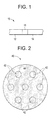
- FIG 1 illustrates a superconductive wire 10 wherein n equals 2, comprising a first wire segment 12, a second wire segment 14, and joint 16 linking first wire segment 12 to second wire segment 14.
- the superconductive wire can comprise any number of wire segments so long as adjacent wire segments differ in at least one of magnetic field tolerance, temperature tolerance, ac loss, or strain tolerance, and the performance of the superconductive wire is not adversely affected by the additional wire segments. Adjacent segments can have different superconductive compositions, or comprise different morphologies of the same composition that express different Ic(H) behavior.
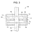
- FIG. 2 is a schematic representing a cross-sectional view of an exemplary wire segment 40.
- Wire segment 40 includes at least one superconductive filament 42 comprising a superconductive composition. Although seven such filaments 42 are represented in the FIG. 2 , there is no limit to the number of filaments 42 contained within wire segment 40. In one embodiment as shown in the FIG. 2 , at least a portion of the filaments are encapsulated in an optional metal matrix 44, which facilitates the establishment of continuous length of superconductive filament.
- the wire segment 40 does not have a metal matrix 44 and consists essentially of one or more bundled superconductive filaments 42 comprising a superconductive composition.
- Exemplary superconductive compositions include NbTi, Nb 3 Sn, MgB 2 , YBa 2 Cu 3 O 7 (referred to as YBCO), bismuth-strontium-calcium-copper-oxygen compounds such as BSCCO-2223 (Bi 2 Sr 2 Ca 2 Cu 3 O 10 ), BSCCO-2212 (Bi 2 Sr 2 Ca 1 Cu 2 O 8 ), TlBa 2 Ca 2 Cu 3 O 9 , Tl 2 Ba 2 CaCu 2 O 8 , (TlPb)Sr 2 CaCu 2 O 7 , (TlPb)Sr 2 Ca 2 Cu 3 O 9 , and combinations thereof.
- BSCCO-2223 Bi 2 Sr 2 Ca 2 Cu 3 O 10
- BSCCO-2212 Bi 2 Sr 2 Ca 1 Cu 2 O 8
- TlBa 2 Ca 2 Cu 3 O 9 Tl 2 Ba 2 CaCu 2 O 8
- TlPb)Sr 2 CaCu 2 O 7 TlPb)Sr 2 Ca 2 Cu 3 O 9
- the superconductive compositions can further comprise dopants.
- the dopants in addition to providing metallic phase support can be incorporated for purposes of changing lattice configurations or spacing and/or improving superconductive properties.
- useful dopants include copper, gold, silver, magnesium, zinc, lead, iron, cadmium, tin, bismuth, gallium, mercury and indium or a combination comprising at least one of the foregoing dopants.
- the superconductive composition has a superconductive phase in a volume fraction effective to provide superconductivity at an operative critical temperature.
- the superconductive phase can occupy a volume greater than or equal to about 19 volume percent of the total superconductive composition. It is generally preferred for the volume fraction of the first superconductive phase to be present in an amount of greater than or equal to about 25, more particularly greater than or equal to about 35, still more particularly greater than or equal to about 50, and even more particularly greater than or equal to about 75 volume percent of the total superconductive composition.
- a wire segment comprises at least one superconductive filament having a filament characteristic dimension, wherein the filament is continuous.
- the metallic matrix material 44 surrounding the superconductive filament is optional, but when used can be either electrically non-conductive or conductive at cryogenic temperatures (i.e., below about 77 K). In order to prevent breakage of wire segment 40 during cycling between room temperature and cryogenic temperatures, the metallic matrix 44 has a coefficient of thermal expansion that is substantially the same as or greater than that of the superconductive composition.
- the metal matrix can be a tube, a billet, and the like, having holes into which either the superconductive composition or the precursors to the superconductive composition (such as Nb and Ti or Sn, or magnesium and boron) can be deposited.
- the metal matrix is comprised of copper or a copper alloy, with a second metal layer disposed between the superconductive composition and the copper.
- the second metal layer is either a barrier layer or a high resistivity layer.
- the barrier layer is selected from the group consisting of tantalum, niobium, nickel, nickel alloys, iron, tungsten, molybdenum and combinations thereof.
- the resistivity layer is selected from the group consisting of cobalt, manganese, a nickel titanium alloy or a nickel zirconium alloy.
- the holes can have the same average radius.
- the radiuses of the individual holes do not, however, always have to be equal to another.
- the holes can have any desired geometry.
- the geometrical cross-section of one hole is circular, the other can be elliptical, and so on.
- the ratio of the radius of any one hole to the radius of the tube can be about 0.1 to about 0.99. Within this range, a ratio of greater than or equal to about 0.15, more particularly greater than or equal to about 0.2, and even more particularly greater than or equal to about 0.25 is desirable.
- Filaments having the superconductive composition can be manufactured by a number of different methods.
- the metallic tube having at least one cylindrical hole through its length is filled with the superconductive composition and is then subjected to a deformation process to reduce the cross-sectional area of the tube as well as to increase its length.
- the superconductive composition comprises NbTi or Nb 3 Sn.
- the metallic tube can have any number of non-intersecting holes that extend from a first end of the tube through to the second end of the tube and at least one of these holes is filled with the superconductive composition prior to the elongation process.
- the first end and the second end of the tube are each located at a diametrical cross-section of the tube. It is generally desirable for the particles that constitute the superconductive composition to be in electrical communication with at least one other particle of the powder prior to the deformation process.
- the metallic tube containing the superconductive composition is then sealed prior to the deformation.
- the deformation can involve processes such as extrusion, forging, rolling, swaging, drawing, and the like, as well as combinations comprising at least one of the foregoing processes.
- the deformation is conducted to extend the length of the tube and to reduce the cross-sectional area. It is generally desirable for the change in length per deformation process to be greater than or equal to about 5%, based on the original length of the tube. In general a change is length of greater than or equal to about 10, more particularly greater than or equal to about 50, and even more particularly greater than or equal to about 100% of the original length is desirable.
- the deformation of the tube is generally conducted in such a manner so as to permit the particles of the superconductive composition in the hole to be in continuous electrical communication with one another to form the filament 110.
- the tube is generally deformed to form a superconductive wire having a cross sectional area of about 0.1 mm 2 to about 5 mm 2 .
- cross sectional areas of greater than or equal to about 0.2 mm 2 , more particularly greater than or equal to about 0.3 mm 2 , and even more particularly greater than or equal to about 0.5 mm 2 , can be used.
- cross sectional areas of less than or equal to about 4.5 mm 2 , more particularly less than or equal to about 4.2 mm 2 , and even more particularly less than or equal to about 3.5 mm 2 .
- the metal matrix comprises about 20% to about 80% of the cross-sectional area of the wire segment.
- the metal matrix can comprise cross sectional areas of greater than or equal to about 25%, more particularly greater than or equal to about 30%, and even more particularly greater than or equal to about 35%, of the superconductive wire.
- the metal matrix can also comprise a cross sectional area of less than or equal to about 75%, more particularly less than or equal to about 70%, and even more particularly less than or equal to about 65%, of the wire segment.
- the wire segment can be further flattened to a tape or film if desired.
- the wire segment, tape or film can be heat treated to improve the superconductive properties and/or the mechanical properties.
- the heat treatment process involves heating the wire segment to a temperature of greater than or equal to about 600° C., more particularly greater than or equal to about 800° C., and even more particularly greater than or equal to about 900° C.
- the time period for the heat treatment is about 1 to about 6 hours. More particularly, the period for the heat treatment is greater than or equal to about 2 hours.
- the wire segment upon cooling provides the resulting superconductive composition with the structure effective for displaying superconductive properties.
- the wire segment comprising a metallic tube having at least one hole is filled with materials used to make a superconductive composition along with any desired dopants.
- exemplary dopants include copper, gold, silver, magnesium, zinc, lead, cadmium, tin, bismuth, gallium, mercury, indium or combinations comprising at least one of the foregoing metals.
- the tube is then sealed and subjected to deformation, as noted above.
- the wire segment is then heat treated to temperatures of greater than or equal to about 700° C. to produce the superconductive composition in the wire segment.
- the wire segment can be drawn into a film, tape, or the like.
- a suitable metallic tube in the form of a billet having at least one hole is filled with magnesium rods, pellets, powder, particles, flakes, and the like. Dopants such as those listed above can also be added into the hole along with the rods, pellets, powder, particles, flakes, and the like of materials used to make the superconductive composition.
- the metallic tube can be a metal that does not form a complex upon exposure to a dopant.
- the metallic tube can be a metal that permits the diffusion of the dopant through it within a reasonable time period.
- Suitable examples of the metal used in the metallic tube (billet) for this manner of manufacturing the wire segment are a copper alloy, stainless steel, tantalum, magnesium or an oxide dispersion strengthened copper and nickel alloys.
- the metallic tube is then sealed and subjected to deformation to produce a wire segment having a reduced cross-sectional area and increased length. It is desirable for the metal to exist in the form of a continuous filament having a length equal to that of the wire segment. This permits the formation of a filament having a superconductive composition through the entire length of the wire segment upon exposure of the wire segment to a dopant.
- the wire segment containing the filament is contacted with dopant to permit the diffusion of the dopant into the metal and eventually upon heat treatment of the wire segment to form a superconductive composition. It is generally desirable for the wire segment to have the ability to continuously superconduct electricity from a first end to the second end and also for the length of the superconductive filament to be at least equal to or greater than the distance from the first end to the second end of the wire segment. In yet another embodiment, any of the aforementioned methods of preparing the wire segment can be combined to either produce the wire segment or to improve its properties.
- Each wire segment of the superconductive wire can be of any desired length. More particularly, the wire segments have a length of about 1 meter to about 1000 meters. Within this range it is generally desirable to have a length of greater than or equal to about 2 meters, more particularly greater than or equal to about 5 meters, and even more particularly greater than or equal to about 8 meters. Also desirable within this range is a length of less than or equal to about 900 meters, more particularly less than or equal to about 800 meters and even more particularly less than or equal to about 500 meters.
- the wire segments can be joined by welds or diffusion bonding to produce a continuous length of superconductive wire having a length at least equal to the sum of the lengths of each of the wire segments.
- the joining of a first wire segment to a second wire segment produces a superconductive wire having a length greater than or equal to the length of the first wire segment or the length of the second wire segment.
- Diffusion bonding is a solid phase process achieved via atomic migration with no macro-deformation of the portions of the wire segments to be bonded. Initial cleanliness of the wire segments is desirable. Surface roughness values of less than 0.4 microns are desirable and the samples can be cleaned in acetone or another solvent prior to bonding. Pressure can be used if desired to effect the diffusion bonding.
- the joining involves contacting a first end of a first wire segment to a second end of a second wire segment; heating the first end of the first wire segment with the second end of the second wire segment at a point to form a single wire, wherein the superconductive filament having the superconductive composition is in continuous electrical contact with any other part of the superconductive filament.
- the point at which the two wires are heated can be a single spot or it can be a section at which the two wires overlap.
- the joint can be a spot weld or a butt weld, or any other kind of weld desired. In one embodiment the weld is formed during the winding process of manufacturing the field coil.
- the joining is generally carried out using at least one source of energy, such as, the energy provided by a beam of light, wherein the energy provided by the source is directed at those portions of the superconductive composition that are to be joined together.
- the interaction of the energy with the superconductive composition facilitates the heating of the composition, and this increase in the temperature can be advantageously utilized to facilitate the joining of the superconductive composition.
- Preferable methods of joining are electron beam welding, laser welding, ultrasonic welding, plasma arc welding, resistance welding and the like.
- the metal matrix may first be removed to expose the superconductive composition in the wire segments that are to be joined.
- the metal matrix can be removed by methods such as chemical etching, mechanical abrasion such as polishing and grinding, thermal treatments such as melting of degradation, or the like, or combinations comprising at least one of the foregoing methods.
- the exposed ends of the superconductive filament can be optionally cleaned with a solvent if desired.
- the exposed portion of the superconductive filament is then heated by contacting it with a source of energy such as an electron beam, laser beam, plasma arc, resistance heating and the like.
- the heated portions of the superconductive filaments are then joined together and cooled to form a weld.
- the heated superconductive filaments are joined together under pressure.
- the joining is generally conducted in an inert atmosphere to prevent oxidation of the superconductive composition in the superconductive filaments.
- the two ends are brought together to form an overlapping section.
- a filler material or dopant can be placed on the overlapping section.
- the overlapping section is then joined using one of the aforementioned joining methods to form a continuous section of the superconductive filament.
- the overlapping section comprising the exposed ends of the superconductive filaments along with a filler material, for example powdered NbTi or Nb 3 Sn, are resistively heated.
- the heating promotes a chemical reaction between the filler material and the substrate filament.
- the filler material can be used to facilitate the joining of the superconductive filament segments.
- the joining generally occurs at a temperature of about 650° C. to about 1000° C. Within this range, a temperature of greater than or equal to about 700° C., more particularly greater than or equal to about 725° C., and even more particularly greater than or equal to about 750° C., can be used. Also desirable are temperatures of less than or equal to about 950° C., more particularly less than or equal to about 900° C., and even more particularly less than or equal to about 875° C. An exemplary temperature is about 795° C. to about 850° C.
- electrical machines comprising an electrical component comprising a superconductive wire, the wire comprising n wire segments joined by n-1 joints; wherein n is an integer greater than or equal to 2; and wherein adjacent wire segments differ in at least one property selected from the group consisting of magnetic field tolerance, temperature tolerance, ac loss, and strain tolerance; wherein the magnetic field tolerance is measured by the relationship of critical current Ic to magnetic field H at a given temperature T below critical temperature Tc, the temperature tolerance is measured by the relationship of critical current Ic to temperature T at a given magnetic field below critical magnetic field Hc, the ac loss is measured by the amount of ac loss versus the frequency and magnitude of applied ac currents and fields, and the strain tolerance is measured by critical current Ic degradation with strain.
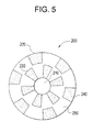
- FIG. 3 is a schematic cross-sectional view of a non-limiting example of a machine 100 comprising an electrical component in the form of a field coil comprising a superconductive wire.
- the machine 100 can operate as a motor and/or as a generator as desired.
- the machine 100 includes a rotor assembly 110 having a pair of rotor segments 106, 108 mounted on a shaft 120.
- the shaft 120 can be formed of any material, more particularly of a non-ferromagnetic material, such as stainless steel.
- the rotor segments 106, 108 are adapted to rotate as the shaft rotates about its longitudinal axis 130 and are spaced-apart axially along the shaft 120.
- Each rotor segment 106, 108 includes a plurality of salient poles, such as iron poles 112 and a plurality of air poles 114.
- the rotor assembly 110 is substantially enclosed within a stationary housing 140.
- the housing 140 rotatably supports the rotor assembly 110.
- the housing 140 is of a substantially cylindrical configuration.
- a stator assembly 150 is also supported within the housing 140 and is stationary relative to the housing 140.
- the stator assembly 150 includes a stator 160 having stator windings (not shown) and a stationary field coil 170 comprising the functionally graded superconductive wire.
- the field coil 170 is mounted on the stator 160.
- the field coil 170 is mechanically decoupled from the rotor assembly 110.
- the field coil 170 when cooled to superconductive temperatures, has substantially zero resistance to electrical current flow.
- the field coil 170 and the salient poles 112 are configured relative to each other such that a rotating magnetic field with a substantially axial air gap flux is produced when the rotor segments 106, 108 are rotated relative to the stator 160 around a predetermined axis.
- the air gap flux direction is substantially parallel to the longitudinal axis 130 of the shaft 120.
- the rotor and the stator are offset axially with the field coil being stationary relative to the stator.
- the poles of the rotor are formed on a planar surface that is substantially perpendicular to the rotational axis of the rotor.
- the superconductive field coil is positioned in plane that is axially offset from the plane of the poles of the rotor.
- the machine 100 can operate as an electrical generator or as a motor.
- the shaft 120 and the rotor assembly 110 are rotated about the longitudinal axis 130 of the shaft 120.
- the rotation of the shaft 120 and the rotor assembly 110 can be performed by applying a torsional force coupled to the shaft 120.
- the field coil 170 is cooled to the superconducting state at a temperature below its transition temperature Tc.
- an electrical current is supplied to the field coil 170 it acts as a stationary magnetomotive force (MMF) source which interacts with a rotating permeance wave of the rotating poles of the rotor to produce a rotating AC magnetic field.
- the rotating magnetic field has an air gap flux directed substantially axially along the longitudinal axis 130 of the shaft 120 and is magnetically coupled to the stator (aperture) windings (not shown) which allows electrical power to be generated.
- the field coil 170 is stationary relative to the housing 140, while the rotor assembly 110 rotates relative to the housing 140 such that a relative difference in rotational speed between the rotor assembly 110 and the magnetic field generated by the field coil 170 is the rotational speed of rotor 110.
- FIG. 4 illustrates a three dimensional view of the machine 100 according to an embodiment where the stator assembly 150 comprises inner 162 and outer stators 164.
- the superconductive field coil 170 is mounted on a ring shaped inner stator 162.
- a ring shaped outer stator 164 is located concentrically around the inner stator 162, such that the coil 170 is located between the inner 162 and outer 164 stators.
- the field coil 170 can be mounted on the outer stator 164 or on both the inner and outer stators.
- the rotor segments 106 and 108 comprising salient poles 112 and air poles 114 are located axially on either side of the stators 162, 164, as shown in FIG. 4 .
- a plurality of such rotor/stator arrangements can be stacked axially along the rotor shaft 120 for long machines.
- the armature windings are not shown in FIG. 4 for clarity.
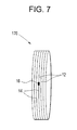
- FIG. 5 is a plane view of an exemplary rotor segment 200 that can be used with machine 100 of FIG. 3 .
- the rotor segment 200 includes a central portion 210 for engaging the shaft (see FIG. 3 ). This central portion 210 can be adapted to accommodate fixtures or adapters which secure the rotor segment 200 to the shaft.
- the rotor segment 200 is preferably formed of a disk-shaped base 250 that is divided into one or more concentric rings.
- the base 250 is divided into a plurality of concentric rings, such as two rings 220, 230.
- the base 250 is made of a ferromagnetic material to allow flux to travel therewithin.
- Each ring is provided with a plurality of spaced-apart ferromagnetic poles 240 formed on a surface of the base 250.
- the salient ferromagnetic poles 240 are formed with iron plates mounted on the surface of the base 250.
- the salient poles 240 are formed of laminated iron.
- the salient poles 240 and the base 250 are of a unitary construction.
- Space between the ferromagnetic poles 240 forms air gaps, or air poles.
- the ferromagnetic poles 240 in adjacent rings are preferably offset by one pole pitch either within or between the concentric rings.
- the salient poles 240 and the air poles therebetween are either annular sector shaped or trapezoidal shaped.
- a plurality of poles is formed in each ring such that the poles are circumferentially spaced apart.
- FIG. 6 illustrates a three dimensional view of the stator assembly 150 with armature windings 166.
- the assembly 150 also includes end windings 168.
- the armature windings can be lap/wave windings.
- the stator assembly 150 is adapted to be housed between a pair of axially spaced-apart rotor segments, as illustrated in FIG. 3 .
- the armature windings 166 are positioned between stator teeth along the circumferential perimeter on each side of the inner and outer stators.
- FIG 7 illustrates an embodiment of a superconductive field coil 170 comprising a functionally graded superconducting wire comprising two wire segments, 12 and 14 joined together by joint 16.
- Joint 16 can be generated during the winding process of forming field coil 170.
- the lengths of wire segments 12 and 14 depend on the magnetic field characteristics and field coil size, which can be readily determined by those of ordinary skill. Otherwise, the lengths are selected to concentrate the windings of the more field tolerant wire segment in the high field region produced by the field coil 170.
- the superconductive field coil 170 is maintained at a temperature approaching zero Kelvin using a continuous supply of cryogenic fluid, such as, for example, but not limited to liquid helium (He). If a high temperature superconductor (HTS) is used in fabricating the field coil, a cryogenic fluid such as nitrogen (N 2 ) or liquid neon (Ne) can be used to achieve superconductive temperatures.
- cryogenic fluid is typically supplied to the superconductive field coil from a stationary cryocooler. Any suitable cooling fluid devices, such as cooling fluid tubes or conduits can be provided in the stator assembly 150 to cool the superconductive field coil 170.
- a superconductive field coil for a rotating machine has been used to exemplify a machine which can usefully employ a functionally graded superconductive wire
- a variety of other power equipment can also benefit from functional grading of the superconductive wires within their coils, because all of these equipment can have varying conditions of magnetic field, temperature, or strain across their coils.
- Examples of such machines include MRI magnets, superconductive transformers, and motor/generators having superconductive armature windings.
- the electrical component comprises a cable comprising one or more functionally graded superconductive wires comprising two or more joined wire segments wherein adjacent wire segments differ in at least one property selected from the group consisting of magnetic field tolerance, temperature tolerance, ac loss, and strain tolerance.
- the superconductive wires are wound around a central axis of the cable. In another embodiment, the superconductive wires are wound in more than one layer.
- the above-described machines comprising a field coil exemplify non-limiting implementations of functionally graded superconductive wires.
- the wire segments of the field coil are positioned to dispose the most field tolerant wire segments within or in closest proximity to the highest field region produced by the field coil. This permits higher current to the field coil and improves torque density for a given coil size and configuration.
- a process of forming a superconductive field coil comprising a superconductive wire comprising winding a first wire segment; joining a second wire segment to the first wire segment; and winding the second wire segment about the first wire segment, wherein the first wire segment and the second wire segment differ in at least one property selected from the group consisting of magnetic field tolerance, temperature tolerance, ac loss, and strain tolerance; and wherein the magnetic field tolerance is measured by the relationship of critical current Ic to magnetic field H at a given temperature T below critical temperature Tc, the temperature tolerance is measured by the relationship of critical current Ic to temperature T at a given magnetic field below critical magnetic field Hc, the ac loss is measured by the amount of ac loss versus the frequency and magnitude of applied ac currents and fields, and the strain tolerance is measured by critical current Ic degradation with strain.
- the wire segments are joined during the winding process. In one embodiment the wire segments are joined by welding. In one embodiment the wire segments are joined by diffusion bonding. In one embodiment the second wire segment comprises Nb 3 Sn and is positioned to define a high field region of the field coil, and the first wire segment comprises NbTi and is positioned to define a low-field region of the field coil, wherein the second magnetic field tolerance of the second wire segment is greater than the first magnetic field tolerance of the first wire segment.
Landscapes
- Engineering & Computer Science (AREA)
- Power Engineering (AREA)
- Superconductors And Manufacturing Methods Therefor (AREA)
- Superconductor Devices And Manufacturing Methods Thereof (AREA)
Abstract
Description
- The present disclosure relates generally to superconductive wire, methods of manufacture, and uses thereof in electronic components.
- Typical superconductive (SC) rotating machines such as electrical motors and generators comprise a SC field coil and non-superconductive armature windings located, for example, on a stationary stator. When supplied a voltage, the field coil generates a magnetic field coupling the field coil and the armature windings. The magnitude of the coupling magnetic field is determined by the amount of current passed through the field coil and to a lesser extent by the armature reaction current from the load. The magnetic stress within the machine translates to torque resulting in rotation of the rotor. The higher the magnetic field, the greater the torque per rotation for a given circumference of armature windings and air gap surface area. Although the armature windings can also be superconductive, they are usually formed of non-SC material such as copper.
- In established commercial superconductive (SC) wires, such as NbTi or Nb3Sn, the current carrying capacity is a function of the critical current Ic, the current where the material has a phase transition from a superconductive phase to a non-superconductive phase. Ic is a decreasing function of temperature T and magnetic field H. These SC wires also differ in price and manufacturing cost; for example, NbTi has a lower price and manufacturing cost, but also lower Ic than Nb3Sn. Superconductors also have a transition from the superconductive to non-superconductive phase at a transition temperature Tc and a critical field Hc, and it follows that they must be operated below this temperature and field.
- In SC field coils, such as those used in SC electric motors and generators, the magnetic field H varies with location on the field coil, usually being higher at the inner parts of the coil, such as the inner surface or bore of a solenoid. Herein, the inner part of the field coil is referred to as the high-field region and the outer part of the coil, such as the outer surface of a solenoid, is referred to as the low-field region. One drawback of SC materials used to manufacture field coils is that some are more tolerant of the magnetic field than others. Less tolerant materials also tolerate lower current, which translates to weaker magnetic field strengths and less torque per given weight of SC material.
- An ongoing need in superconductive rotating motors is reduction in the size and weight of the machines; that is, increasing the torque density for a given circumference of the field coil and armature windings. The practical benefits from miniaturization through more field tolerant electrical components in these and other machines include lower manufacturing costs, among others. This disclosure addresses the need for more field tolerant components.
- Disclosed herein are functionally graded superconductive wires for electrical components such as, for example, superconductive field coils for motors and generators.
- In one embodiment, an electrical component comprises a superconductive wire, the wire comprising a first wire segment joined to a second wire segment; wherein the first wire segment and the second wire segment differ in at least one property selected from the group consisting of magnetic field tolerance, temperature tolerance, ac loss, and strain tolerance; and wherein the magnetic field tolerance is measured by the relationship of critical current Ic to magnetic field H at a given temperature T below critical temperature Tc, the temperature tolerance is measured by the relationship of critical current Ic to temperature T at a given magnetic field below critical magnetic field Hc, the ac loss is measured by the amount of ac loss versus the frequency and magnitude of applied ac currents and fields, and the strain tolerance is measured by critical current Ic degradation with strain.
- In one embodiment, a process of forming a superconductive field coil, comprises winding a first wire segment; joining a second wire segment to the first wire segment; and winding the second wire segment about the first wire segment, wherein the first wire segment and the second wire segment differ in at least one property selected from the group consisting of magnetic field tolerance, temperature tolerance, ac loss, and strain tolerance; and wherein the magnetic field tolerance is measured by the relationship of critical current Ic to magnetic field H at a given temperature T below critical temperature Tc, the temperature tolerance is measured by the relationship of critical current Ic to temperature T at a given magnetic field below critical magnetic field Hc, the ac loss is measured by the amount of ac loss versus the frequency and magnitude of applied ac currents and fields, and the strain tolerance is measured by critical current Ic degradation with strain.
- In one embodiment, a machine comprises an electrical component comprising a superconductive wire, the wire comprising n wire segments joined by n-1 joints; wherein n is an integer greater than or equal to 2; and wherein adjacent wire segments differ in at least one property selected from the group consisting of magnetic field tolerance, temperature tolerance, ac loss, and strain tolerance; and wherein the magnetic field tolerance is measured by the relationship of critical current Ic to magnetic field H at a given temperature T below critical temperature Tc, the temperature tolerance is measured by the relationship of critical current Ic to temperature T at a given magnetic field below critical magnetic field Hc, the ac loss is measured by the amount of ac loss versus the frequency and magnitude of applied ac currents and fields, and the strain tolerance is measured by critical current Ic degradation with strain.
- Other features and advantages will be or become apparent to one with skill in the art upon examination of the following drawings and detailed description.
- In the drawings, like reference numerals designate corresponding parts throughout the several views, in which:
-
FIG. 1 is a schematic of a functionally graded superconductive wire for an electrical component; -
FIG. 2 is a schematic cross-section of an exemplary wire segment comprising several superconductive filaments; -
FIG. 3 is a cross-sectional view of an exemplary machine having a rotatable shaft and a stator; -
FIG. 4 is a perspective view of an exemplary stator showing a field coil on the inner stator; -
FIG. 5 is a plane view of an exemplary embodiment of a rotor segment for the machine shown inFIG. 2 ; -
FIG. 6 is a perspective view of the assembled stator ofFig 4 ; and -
FIG 7 is a schematic of a superconductive field coil comprising a superconductive wire having two wire segments. - Disclosed herein are functionally graded superconductive wires for electrical components of power equipment such as motors and generators and other electrical machines. The superconductive wires comprise n wire segments joined by n-1 joints, wherein n is an integer greater than or equal to 2. Functional grading refers to adjacent wire segments having different properties with respect to at least one of magnetic field tolerance, temperature tolerance, ac loss, and strain tolerance. The functionally graded superconductive wire (herein "superconductive wire") can enhance, for example, the magnetic field capability of an electrical component such as a superconductive field coil of a motor or generator, allowing it to operate at higher current and generate greater magnetic stress, and advantageously produce increased torque per rotation of a given circumference of the armature windings and air gap surface area compared to a superconductive field coil comprising a non-functionally graded wire.
- In one embodiment an electrical component comprises a superconductive wire, the wire comprising a first wire segment joined to a second wire segment; wherein the first wire segment and the second wire segment differ in at least one property selected from the group consisting of magnetic field tolerance, temperature tolerance, ac loss, and strain tolerance, wherein the magnetic field tolerance is measured by the relationship of critical current Ic to magnetic field H at a given temperature T below critical temperature Tc, the temperature tolerance is measured by the relationship of critical current Ic to temperature T at a given magnetic field below critical magnetic field Hc, the ac loss is measured by the amount of ac loss versus the frequency and magnitude of applied ac currents and fields, and the strain tolerance is measured by critical current Ic degradation with strain.
- In one embodiment, the first and second wire segments are formed of different superconductive compositions. In one embodiment the superconductive wire comprises at least one additional wire segment joined to the second wire segment; wherein adjacent wire segments differ in at least one of the aforementioned properties. In one embodiment the electrical component comprises a plurality of adjacent layers or lengths of the superconductive wire. In one embodiment, the electrical component is a cable or a coil.
-
FIG 1 illustrates asuperconductive wire 10 wherein n equals 2, comprising afirst wire segment 12, asecond wire segment 14, and joint 16 linkingfirst wire segment 12 tosecond wire segment 14. The superconductive wire can comprise any number of wire segments so long as adjacent wire segments differ in at least one of magnetic field tolerance, temperature tolerance, ac loss, or strain tolerance, and the performance of the superconductive wire is not adversely affected by the additional wire segments. Adjacent segments can have different superconductive compositions, or comprise different morphologies of the same composition that express different Ic(H) behavior. -
FIG. 2 is a schematic representing a cross-sectional view of anexemplary wire segment 40.Wire segment 40 includes at least onesuperconductive filament 42 comprising a superconductive composition. Although sevensuch filaments 42 are represented in theFIG. 2 , there is no limit to the number offilaments 42 contained withinwire segment 40. In one embodiment as shown in theFIG. 2 , at least a portion of the filaments are encapsulated in anoptional metal matrix 44, which facilitates the establishment of continuous length of superconductive filament. - In another exemplary embodiment (not shown), the
wire segment 40 does not have ametal matrix 44 and consists essentially of one or more bundledsuperconductive filaments 42 comprising a superconductive composition. - Exemplary superconductive compositions include NbTi, Nb3Sn, MgB2, YBa2Cu3O7 (referred to as YBCO), bismuth-strontium-calcium-copper-oxygen compounds such as BSCCO-2223 (Bi2Sr2Ca2Cu3O10), BSCCO-2212 (Bi2Sr2Ca1Cu2O8), TlBa2Ca2Cu3O9, Tl2Ba2CaCu2O8, (TlPb)Sr2CaCu2O7, (TlPb)Sr2Ca2Cu3O9, and combinations thereof.
- The superconductive compositions can further comprise dopants. The dopants in addition to providing metallic phase support can be incorporated for purposes of changing lattice configurations or spacing and/or improving superconductive properties. Depending upon the chemical composition of the first superconductive phase, useful dopants that can be added include copper, gold, silver, magnesium, zinc, lead, iron, cadmium, tin, bismuth, gallium, mercury and indium or a combination comprising at least one of the foregoing dopants.
- Irrespective of the other components present in the superconductive composition, the superconductive composition has a superconductive phase in a volume fraction effective to provide superconductivity at an operative critical temperature. In one embodiment, the superconductive phase can occupy a volume greater than or equal to about 19 volume percent of the total superconductive composition. It is generally preferred for the volume fraction of the first superconductive phase to be present in an amount of greater than or equal to about 25, more particularly greater than or equal to about 35, still more particularly greater than or equal to about 50, and even more particularly greater than or equal to about 75 volume percent of the total superconductive composition.
- A wire segment comprises at least one superconductive filament having a filament characteristic dimension, wherein the filament is continuous. The
metallic matrix material 44 surrounding the superconductive filament is optional, but when used can be either electrically non-conductive or conductive at cryogenic temperatures (i.e., below about 77 K). In order to prevent breakage ofwire segment 40 during cycling between room temperature and cryogenic temperatures, themetallic matrix 44 has a coefficient of thermal expansion that is substantially the same as or greater than that of the superconductive composition. - The metal matrix can be a tube, a billet, and the like, having holes into which either the superconductive composition or the precursors to the superconductive composition (such as Nb and Ti or Sn, or magnesium and boron) can be deposited. In an optional embodiment, the metal matrix is comprised of copper or a copper alloy, with a second metal layer disposed between the superconductive composition and the copper. The second metal layer is either a barrier layer or a high resistivity layer. In one embodiment, the barrier layer is selected from the group consisting of tantalum, niobium, nickel, nickel alloys, iron, tungsten, molybdenum and combinations thereof. In another embodiment, the resistivity layer is selected from the group consisting of cobalt, manganese, a nickel titanium alloy or a nickel zirconium alloy.
- If the tube has more than one hole, it is generally desirable for the holes to have the same average radius. The radiuses of the individual holes do not, however, always have to be equal to another. In addition the holes can have any desired geometry. For example while the geometrical cross-section of one hole is circular, the other can be elliptical, and so on. The ratio of the radius of any one hole to the radius of the tube can be about 0.1 to about 0.99. Within this range, a ratio of greater than or equal to about 0.15, more particularly greater than or equal to about 0.2, and even more particularly greater than or equal to about 0.25 is desirable.
- Filaments having the superconductive composition can be manufactured by a number of different methods. In one exemplary method of manufacturing the superconductive composition in the form of a wire, the metallic tube having at least one cylindrical hole through its length is filled with the superconductive composition and is then subjected to a deformation process to reduce the cross-sectional area of the tube as well as to increase its length. In an exemplary embodiment, the superconductive composition comprises NbTi or Nb3Sn. The metallic tube can have any number of non-intersecting holes that extend from a first end of the tube through to the second end of the tube and at least one of these holes is filled with the superconductive composition prior to the elongation process. The first end and the second end of the tube are each located at a diametrical cross-section of the tube. It is generally desirable for the particles that constitute the superconductive composition to be in electrical communication with at least one other particle of the powder prior to the deformation process.
- The metallic tube containing the superconductive composition is then sealed prior to the deformation. The deformation can involve processes such as extrusion, forging, rolling, swaging, drawing, and the like, as well as combinations comprising at least one of the foregoing processes. The deformation is conducted to extend the length of the tube and to reduce the cross-sectional area. It is generally desirable for the change in length per deformation process to be greater than or equal to about 5%, based on the original length of the tube. In general a change is length of greater than or equal to about 10, more particularly greater than or equal to about 50, and even more particularly greater than or equal to about 100% of the original length is desirable. The deformation of the tube is generally conducted in such a manner so as to permit the particles of the superconductive composition in the hole to be in continuous electrical communication with one another to form the
filament 110. - The tube is generally deformed to form a superconductive wire having a cross sectional area of about 0.1 mm2 to about 5 mm2. Within this range, cross sectional areas of greater than or equal to about 0.2 mm2, more particularly greater than or equal to about 0.3 mm2, and even more particularly greater than or equal to about 0.5 mm2, can be used. Also desirable within this range are cross sectional areas of less than or equal to about 4.5 mm2, more particularly less than or equal to about 4.2 mm2, and even more particularly less than or equal to about 3.5 mm2. In general, the metal matrix comprises about 20% to about 80% of the cross-sectional area of the wire segment. Within this range, the metal matrix can comprise cross sectional areas of greater than or equal to about 25%, more particularly greater than or equal to about 30%, and even more particularly greater than or equal to about 35%, of the superconductive wire. The metal matrix can also comprise a cross sectional area of less than or equal to about 75%, more particularly less than or equal to about 70%, and even more particularly less than or equal to about 65%, of the wire segment. The wire segment can be further flattened to a tape or film if desired.
- Following the deformation process, the wire segment, tape or film can be heat treated to improve the superconductive properties and/or the mechanical properties. The heat treatment process involves heating the wire segment to a temperature of greater than or equal to about 600° C., more particularly greater than or equal to about 800° C., and even more particularly greater than or equal to about 900° C. The time period for the heat treatment is about 1 to about 6 hours. More particularly, the period for the heat treatment is greater than or equal to about 2 hours. In general, the wire segment upon cooling provides the resulting superconductive composition with the structure effective for displaying superconductive properties.
- In another exemplary method of manufacturing, the wire segment comprising a metallic tube having at least one hole is filled with materials used to make a superconductive composition along with any desired dopants. Exemplary dopants include copper, gold, silver, magnesium, zinc, lead, cadmium, tin, bismuth, gallium, mercury, indium or combinations comprising at least one of the foregoing metals. The tube is then sealed and subjected to deformation, as noted above. The wire segment is then heat treated to temperatures of greater than or equal to about 700° C. to produce the superconductive composition in the wire segment. As noted above, the wire segment can be drawn into a film, tape, or the like.
- In yet another exemplary method of manufacturing the wire segment, a suitable metallic tube in the form of a billet having at least one hole is filled with magnesium rods, pellets, powder, particles, flakes, and the like. Dopants such as those listed above can also be added into the hole along with the rods, pellets, powder, particles, flakes, and the like of materials used to make the superconductive composition. The metallic tube can be a metal that does not form a complex upon exposure to a dopant. In addition the metallic tube can be a metal that permits the diffusion of the dopant through it within a reasonable time period. Suitable examples of the metal used in the metallic tube (billet) for this manner of manufacturing the wire segment are a copper alloy, stainless steel, tantalum, magnesium or an oxide dispersion strengthened copper and nickel alloys.
- The metallic tube is then sealed and subjected to deformation to produce a wire segment having a reduced cross-sectional area and increased length. It is desirable for the metal to exist in the form of a continuous filament having a length equal to that of the wire segment. This permits the formation of a filament having a superconductive composition through the entire length of the wire segment upon exposure of the wire segment to a dopant.
- In order to form the superconductive composition, the wire segment containing the filament is contacted with dopant to permit the diffusion of the dopant into the metal and eventually upon heat treatment of the wire segment to form a superconductive composition. It is generally desirable for the wire segment to have the ability to continuously superconduct electricity from a first end to the second end and also for the length of the superconductive filament to be at least equal to or greater than the distance from the first end to the second end of the wire segment. In yet another embodiment, any of the aforementioned methods of preparing the wire segment can be combined to either produce the wire segment or to improve its properties.
- Each wire segment of the superconductive wire can be of any desired length. More particularly, the wire segments have a length of about 1 meter to about 1000 meters. Within this range it is generally desirable to have a length of greater than or equal to about 2 meters, more particularly greater than or equal to about 5 meters, and even more particularly greater than or equal to about 8 meters. Also desirable within this range is a length of less than or equal to about 900 meters, more particularly less than or equal to about 800 meters and even more particularly less than or equal to about 500 meters.
- Following the manufacturing of a wire segment, the wire segments can be joined by welds or diffusion bonding to produce a continuous length of superconductive wire having a length at least equal to the sum of the lengths of each of the wire segments. In one embodiment, the joining of a first wire segment to a second wire segment produces a superconductive wire having a length greater than or equal to the length of the first wire segment or the length of the second wire segment.
- Diffusion bonding is a solid phase process achieved via atomic migration with no macro-deformation of the portions of the wire segments to be bonded. Initial cleanliness of the wire segments is desirable. Surface roughness values of less than 0.4 microns are desirable and the samples can be cleaned in acetone or another solvent prior to bonding. Pressure can be used if desired to effect the diffusion bonding.
- In one embodiment, the joining involves contacting a first end of a first wire segment to a second end of a second wire segment; heating the first end of the first wire segment with the second end of the second wire segment at a point to form a single wire, wherein the superconductive filament having the superconductive composition is in continuous electrical contact with any other part of the superconductive filament. The point at which the two wires are heated can be a single spot or it can be a section at which the two wires overlap. The joint can be a spot weld or a butt weld, or any other kind of weld desired. In one embodiment the weld is formed during the winding process of manufacturing the field coil.
- In one embodiment, it is generally desired to join the wire segments in a manner effective to have at least one electrically continuous superconductive filament of a length greater than or equal to the length of the joined wire segments.
- The joining is generally carried out using at least one source of energy, such as, the energy provided by a beam of light, wherein the energy provided by the source is directed at those portions of the superconductive composition that are to be joined together. The interaction of the energy with the superconductive composition facilitates the heating of the composition, and this increase in the temperature can be advantageously utilized to facilitate the joining of the superconductive composition. Preferable methods of joining are electron beam welding, laser welding, ultrasonic welding, plasma arc welding, resistance welding and the like.
- In the process of joining a wire segment having a metal matrix, the metal matrix may first be removed to expose the superconductive composition in the wire segments that are to be joined. The metal matrix can be removed by methods such as chemical etching, mechanical abrasion such as polishing and grinding, thermal treatments such as melting of degradation, or the like, or combinations comprising at least one of the foregoing methods. Following the removal of the metal matrix, the exposed ends of the superconductive filament can be optionally cleaned with a solvent if desired. The exposed portion of the superconductive filament is then heated by contacting it with a source of energy such as an electron beam, laser beam, plasma arc, resistance heating and the like. The heated portions of the superconductive filaments are then joined together and cooled to form a weld. In one embodiment, the heated superconductive filaments are joined together under pressure. In another embodiment, the joining is generally conducted in an inert atmosphere to prevent oxidation of the superconductive composition in the superconductive filaments.
- In another embodiment, after the metal matrix is removed from the ends of the superconductive wire to be joined, the two ends are brought together to form an overlapping section. A filler material or dopant can be placed on the overlapping section. The overlapping section is then joined using one of the aforementioned joining methods to form a continuous section of the superconductive filament.
- In yet another embodiment, the overlapping section comprising the exposed ends of the superconductive filaments along with a filler material, for example powdered NbTi or Nb3Sn, are resistively heated. The heating promotes a chemical reaction between the filler material and the substrate filament. The filler material can be used to facilitate the joining of the superconductive filament segments.
- In one embodiment, the joining generally occurs at a temperature of about 650° C. to about 1000° C. Within this range, a temperature of greater than or equal to about 700° C., more particularly greater than or equal to about 725° C., and even more particularly greater than or equal to about 750° C., can be used. Also desirable are temperatures of less than or equal to about 950° C., more particularly less than or equal to about 900° C., and even more particularly less than or equal to about 875° C. An exemplary temperature is about 795° C. to about 850° C.
- Also disclosed are electrical machines comprising an electrical component comprising a superconductive wire, the wire comprising n wire segments joined by n-1 joints; wherein n is an integer greater than or equal to 2; and wherein adjacent wire segments differ in at least one property selected from the group consisting of magnetic field tolerance, temperature tolerance, ac loss, and strain tolerance; wherein the magnetic field tolerance is measured by the relationship of critical current Ic to magnetic field H at a given temperature T below critical temperature Tc, the temperature tolerance is measured by the relationship of critical current Ic to temperature T at a given magnetic field below critical magnetic field Hc, the ac loss is measured by the amount of ac loss versus the frequency and magnitude of applied ac currents and fields, and the strain tolerance is measured by critical current Ic degradation with strain.
-
FIG. 3 is a schematic cross-sectional view of a non-limiting example of amachine 100 comprising an electrical component in the form of a field coil comprising a superconductive wire. Themachine 100 can operate as a motor and/or as a generator as desired. Themachine 100 includes arotor assembly 110 having a pair ofrotor segments shaft 120. Theshaft 120 can be formed of any material, more particularly of a non-ferromagnetic material, such as stainless steel. Therotor segments longitudinal axis 130 and are spaced-apart axially along theshaft 120. Eachrotor segment iron poles 112 and a plurality ofair poles 114. - The
rotor assembly 110 is substantially enclosed within astationary housing 140. Thehousing 140 rotatably supports therotor assembly 110. Thehousing 140 is of a substantially cylindrical configuration. Astator assembly 150 is also supported within thehousing 140 and is stationary relative to thehousing 140. Thestator assembly 150 includes astator 160 having stator windings (not shown) and astationary field coil 170 comprising the functionally graded superconductive wire. In particular, thefield coil 170 is mounted on thestator 160. - The
field coil 170 is mechanically decoupled from therotor assembly 110. Thefield coil 170, when cooled to superconductive temperatures, has substantially zero resistance to electrical current flow. Thefield coil 170 and thesalient poles 112 are configured relative to each other such that a rotating magnetic field with a substantially axial air gap flux is produced when therotor segments stator 160 around a predetermined axis. In a preferred embodiment where the rotor segments are mounted on theshaft 120, the air gap flux direction is substantially parallel to thelongitudinal axis 130 of theshaft 120. - Thus, the rotor and the stator are offset axially with the field coil being stationary relative to the stator. The poles of the rotor are formed on a planar surface that is substantially perpendicular to the rotational axis of the rotor. Further, the superconductive field coil is positioned in plane that is axially offset from the plane of the poles of the rotor. With the rotation of the rotor through a magnetic field generated by the field coil, a rotating magnetic field is produced. The rotating magnetic field has an air gap flux substantially in the axial direction in the region of the stator.
- In operation, the
machine 100 can operate as an electrical generator or as a motor. When themachine 100 operates as a generator, theshaft 120 and therotor assembly 110 are rotated about thelongitudinal axis 130 of theshaft 120. The rotation of theshaft 120 and therotor assembly 110 can be performed by applying a torsional force coupled to theshaft 120. Thefield coil 170 is cooled to the superconducting state at a temperature below its transition temperature Tc. When an electrical current is supplied to thefield coil 170 it acts as a stationary magnetomotive force (MMF) source which interacts with a rotating permeance wave of the rotating poles of the rotor to produce a rotating AC magnetic field. The rotating magnetic field has an air gap flux directed substantially axially along thelongitudinal axis 130 of theshaft 120 and is magnetically coupled to the stator (aperture) windings (not shown) which allows electrical power to be generated. - When the
machine 100 operates as a motor, electrical current is provided to thefield coil 170 ofmachine 100 to generate a rotating magnetic field coupling thefield coil 170 and stator (armature) windings. By doing so a magnetic stress is increased within the machine, resulting in a torque on therotor assembly 110 causingshaft 120 to rotate relative to thestator 160. - In the exemplary embodiment, the
field coil 170 is stationary relative to thehousing 140, while therotor assembly 110 rotates relative to thehousing 140 such that a relative difference in rotational speed between therotor assembly 110 and the magnetic field generated by thefield coil 170 is the rotational speed ofrotor 110. -
FIG. 4 illustrates a three dimensional view of themachine 100 according to an embodiment where thestator assembly 150 comprises inner 162 andouter stators 164. Thesuperconductive field coil 170 is mounted on a ring shapedinner stator 162. A ring shapedouter stator 164 is located concentrically around theinner stator 162, such that thecoil 170 is located between the inner 162 and outer 164 stators. Alternatively, thefield coil 170 can be mounted on theouter stator 164 or on both the inner and outer stators. Therotor segments salient poles 112 andair poles 114 are located axially on either side of thestators FIG. 4 . A plurality of such rotor/stator arrangements can be stacked axially along therotor shaft 120 for long machines. The armature windings are not shown inFIG. 4 for clarity. -
FIG. 5 is a plane view of anexemplary rotor segment 200 that can be used withmachine 100 ofFIG. 3 . Therotor segment 200 includes acentral portion 210 for engaging the shaft (seeFIG. 3 ). Thiscentral portion 210 can be adapted to accommodate fixtures or adapters which secure therotor segment 200 to the shaft. Therotor segment 200 is preferably formed of a disk-shapedbase 250 that is divided into one or more concentric rings. Preferably, thebase 250 is divided into a plurality of concentric rings, such as tworings base 250 is made of a ferromagnetic material to allow flux to travel therewithin. Each ring is provided with a plurality of spaced-apartferromagnetic poles 240 formed on a surface of thebase 250. In a preferred embodiment, the salientferromagnetic poles 240 are formed with iron plates mounted on the surface of thebase 250. In another embodiment, thesalient poles 240 are formed of laminated iron. In yet another embodiment, thesalient poles 240 and the base 250 are of a unitary construction. - Space between the
ferromagnetic poles 240 forms air gaps, or air poles. Theferromagnetic poles 240 in adjacent rings are preferably offset by one pole pitch either within or between the concentric rings. Preferably, thesalient poles 240 and the air poles therebetween are either annular sector shaped or trapezoidal shaped. Thus, a plurality of poles is formed in each ring such that the poles are circumferentially spaced apart. -
FIG. 6 illustrates a three dimensional view of thestator assembly 150 witharmature windings 166. Theassembly 150 also includesend windings 168. The armature windings can be lap/wave windings. Thestator assembly 150 is adapted to be housed between a pair of axially spaced-apart rotor segments, as illustrated inFIG. 3 . Thearmature windings 166 are positioned between stator teeth along the circumferential perimeter on each side of the inner and outer stators. -
FIG 7 illustrates an embodiment of asuperconductive field coil 170 comprising a functionally graded superconducting wire comprising two wire segments, 12 and 14 joined together by joint 16. Joint 16 can be generated during the winding process of formingfield coil 170. The lengths ofwire segments field coil 170. - The
superconductive field coil 170 is maintained at a temperature approaching zero Kelvin using a continuous supply of cryogenic fluid, such as, for example, but not limited to liquid helium (He). If a high temperature superconductor (HTS) is used in fabricating the field coil, a cryogenic fluid such as nitrogen (N2) or liquid neon (Ne) can be used to achieve superconductive temperatures. The cryogenic fluid is typically supplied to the superconductive field coil from a stationary cryocooler. Any suitable cooling fluid devices, such as cooling fluid tubes or conduits can be provided in thestator assembly 150 to cool thesuperconductive field coil 170. - Although a superconductive field coil for a rotating machine has been used to exemplify a machine which can usefully employ a functionally graded superconductive wire, a variety of other power equipment can also benefit from functional grading of the superconductive wires within their coils, because all of these equipment can have varying conditions of magnetic field, temperature, or strain across their coils. Examples of such machines include MRI magnets, superconductive transformers, and motor/generators having superconductive armature windings.
- In another embodiment the electrical component comprises a cable comprising one or more functionally graded superconductive wires comprising two or more joined wire segments wherein adjacent wire segments differ in at least one property selected from the group consisting of magnetic field tolerance, temperature tolerance, ac loss, and strain tolerance. In one embodiment the superconductive wires are wound around a central axis of the cable. In another embodiment, the superconductive wires are wound in more than one layer.
- The above-described machines comprising a field coil exemplify non-limiting implementations of functionally graded superconductive wires. The wire segments of the field coil are positioned to dispose the most field tolerant wire segments within or in closest proximity to the highest field region produced by the field coil. This permits higher current to the field coil and improves torque density for a given coil size and configuration.
- Other electrical generating systems are contemplated using electrical components comprising the functionally graded superconductive wires described herein. The systems are not limited to the specific embodiments described herein, but rather, components of each system can be utilized independently and separately from other components described herein. Each system component can also be used in combination with other system components.
- Also disclosed is a process of forming a superconductive field coil comprising a superconductive wire comprising winding a first wire segment; joining a second wire segment to the first wire segment; and winding the second wire segment about the first wire segment, wherein the first wire segment and the second wire segment differ in at least one property selected from the group consisting of magnetic field tolerance, temperature tolerance, ac loss, and strain tolerance; and wherein the magnetic field tolerance is measured by the relationship of critical current Ic to magnetic field H at a given temperature T below critical temperature Tc, the temperature tolerance is measured by the relationship of critical current Ic to temperature T at a given magnetic field below critical magnetic field Hc, the ac loss is measured by the amount of ac loss versus the frequency and magnitude of applied ac currents and fields, and the strain tolerance is measured by critical current Ic degradation with strain. In one embodiment the wire segments are joined during the winding process. In one embodiment the wire segments are joined by welding. In one embodiment the wire segments are joined by diffusion bonding. In one embodiment the second wire segment comprises Nb3Sn and is positioned to define a high field region of the field coil, and the first wire segment comprises NbTi and is positioned to define a low-field region of the field coil, wherein the second magnetic field tolerance of the second wire segment is greater than the first magnetic field tolerance of the first wire segment.
- The singular forms "a," "an," and "the" in the above description include plural referents unless the context clearly dictates otherwise. The endpoints of all ranges directed to the same characteristic or component are independently combinable and inclusive of the recited endpoint.
- This written description uses examples to disclose the invention, including the preferred mode, and also to enable any person skilled in the art to practice the invention, including making and using any devices or systems and performing any incorporated methods. The patentable scope of the invention is defined by the claims, and may include other examples that occur to those skilled in the art. Such other examples are intended to be within the scope of the claims if they have structural elements that do not differ from the literal language of the claims, or if they include equivalent structural elements with insubstantial differences from the literal languages of the claims.
- Various aspects and embodiments of the present invention are now defined in the following numbered clauses:
- 1. An electrical component comprising a superconductive wire, the wire comprising:
- a first wire segment joined to a second wire segment; wherein the first wire segment and the second wire segment differ in at least one property selected from the group consisting of magnetic field tolerance, temperature tolerance, ac loss, and strain tolerance; and wherein the magnetic field tolerance is measured by the relationship of critical current Ic to magnetic field H at a given temperature T below critical temperature Tc, the temperature tolerance is measured by the relationship of critical current Ic to temperature T at a given magnetic field below critical magnetic field Hc, the ac loss is measured by the amount of ac loss versus the frequency and magnitude of applied ac currents and fields, and the strain tolerance is measured by critical current Ic degradation with strain.
- 2. The electrical component of clause 1, further comprising a plurality of adjacent layers or lengths of the superconductive wire.
- 3. The electrical component of any preceding clause, wherein the electrical component is a cable or a coil.
- 4. The electrical component of any preceding clause, wherein the superconductive wire further comprises at least one additional wire segment joined to the second wire segment; wherein the at least one additional wire segment and the second wire segment differ in at least one property selected from the group consisting of magnetic field tolerance, temperature tolerance, ac loss, and strain tolerance.
- 5. The electrical component of any preceding clause, wherein the first and the second wire segments comprise different superconductive compositions.
- 6. The electrical component of any preceding clause, wherein the superconductive composition is selected from the group consisting of NbTi, Nb3Sn, MgB2, YBa2Cu3O7, BSCCO-2223, BSCCO-2212, TlBa2Ca2Cu3O9, Tl2Ba2CaCu2O8, (TlPb)Sr2CaCu2O7, (TlPb)Sr2Ca2Cu3O9, and combinations thereof.
- 7. The electrical component of any preceding clause, wherein the first and/or the second wire segment comprises more than one filament comprising a superconductive composition.
- 8. The electrical component of any preceding clause, wherein the first and/or the second wire segment comprises a non-superconductive metal matrix surrounding a superconductive filament.
- 9. The electrical component of any preceding clause, wherein the non-superconductive metal matrix is copper or a copper alloy.
- 10. The electrical component of any preceding clause, wherein the first wire segment is formed of NbTi and the second wire segment is formed of Nb3Sn.
- 11. The electrical component of any preceding clause, wherein the first and/or second wire segments further comprise a dopant selected from the group consisting of copper, gold, silver, magnesium, zinc, lead, cadmium, tin, bismuth, gallium, mercury and indium or a combination comprising at least one of the foregoing dopants.
- 12. A process of forming a superconductive field coil comprising a superconductive wire, comprising:
- winding a first wire segment;
- joining a second wire segment to the first wire segment; and
- winding the second wire segment about the first wire segment, wherein
- the first wire segment and the second wire segment differ in at least one property selected from the group consisting of magnetic field tolerance, temperature tolerance, ac loss, and strain tolerance; and wherein
- the magnetic field tolerance is measured by the relationship of critical current Ic to magnetic field H at a given temperature T below critical temperature Tc, the temperature tolerance is measured by the relationship of critical current Ic to temperature T at a given magnetic field below critical magnetic field Hc, the ac loss is measured by the amount of ac loss versus the frequency and magnitude of applied ac currents and fields, and the strain tolerance is measured by critical current Ic degradation with strain.
- 13. The process of
clause 12, wherein the first wire segment is formed of NbTi and defines a low field region and the second wire segment is formed of Nb3Sn and defines a high-field region of the field coil. - 14. The process of
clause 12 or 13, wherein joining the second wire segment to the first wire segment comprises a welding process. - 15. The process of any of
clauses 12 to 14, wherein joining the second wire segment to the first wire segment comprises a diffusion bonding process. - 16. The process of any of
clauses 12 to 15, wherein the first and /or second wire segments comprise a superconductive composition selected from the group consisting of NbTi, Nb3Sn, MgB2, YBa2Cu3O7, BSCCO-2223, BSCCO-2212, TlBa2Ca2Cu3O9, Tl2Ba2CaCu2O8, (TlPb)Sr2CaCu2O7, (TlPb)Sr2Ca2Cu3O9, and combinations thereof. - 17. A machine, comprising
- an electrical component comprising a superconductive wire, the wire comprising n wire segments joined by n-1 joints; wherein n is an integer greater than or equal to 2; and wherein adjacent wire segments differ in at least one property selected from the group consisting of magnetic field tolerance, temperature tolerance, ac loss, and strain tolerance; and wherein the magnetic field tolerance is measured by the relationship of critical current Ic to magnetic field H at a given temperature T below critical temperature Tc, the temperature tolerance is measured by the relationship of critical current Ic to temperature T at a given magnetic field below critical magnetic field Hc, the ac loss is measured by the amount of ac loss versus the frequency and magnitude of applied ac currents and fields, and the strain tolerance is measured by critical current Ic degradation with strain.
- 18. The machine of clause 17, wherein the electronic component is a superconductive field coil.
- 19. The machine of clause 17 or 18, further comprising a rotor assembly comprising a rotatable shaft, and a stationary stator assembly comprising concentric inner and outer stators and a plurality of armature windings, wherein the superconductive field coil is stationary.
- 20. The machine of any of clauses 17 to 19, wherein the machine is a generator.
- 21. The machine of any of clauses 17 to 20, wherein the machine is a motor.
- 22. The machine of any of clauses 17 to 21, wherein the generator is a component of a wind turbine assembly.
Claims (10)
- An electrical component comprising a superconductive wire (10), the wire comprising:a first wire segment (12) joined to a second wire segment (14); whereinthe first wire segment (12) and the second wire segment (14) differ in at least one property selected from the group consisting of magnetic field tolerance, temperature tolerance, ac loss, and strain tolerance; and whereinthe magnetic field tolerance is measured by the relationship of critical current Ic to magnetic field H at a given temperature T below Tc, the temperature tolerance is measured by the relationship of critical current Ic to temperature T at a given magnetic field below Hc, the ac loss is measured by the amount of ac loss versus the frequency and magnitude of applied ac currents and fields, and the strain tolerance is measured by Ic degradation with strain.
- The electrical component of claim 1, wherein the first (12) and the second (14) wire segments comprise different superconductive compositions.
- The electrical component of claim 2, wherein the superconductive composition is selected from the group consisting of NbTi, Nb3Sn, MgB2, YBa2Cu3O7, BSCCO-2223, BSCCO-2212, TlBa2Ca2Cu3O9, Tl2Ba2CaCu2O8, (TlPb)Sr2CaCu2O7, (TlPb)Sr2Ca2Cu3O9, and combinations thereof.
- The electrical component of any of the previous claims, wherein the first wire segment (12) is formed of NbTi and the second wire segment (14) is formed of Nb3Sn.
- A process of forming a superconductive field coil (170) comprising a superconductive wire (10), comprising:winding a first wire segment (12);joining a second wire segment (14) to the first wire segment (12); andwinding the second wire segment (14) about the first wire segment (12), whereinthe first wire segment (12) and the second wire segment (14) differ in at least one property selected from the group consisting of magnetic field tolerance, temperature tolerance, ac loss, and strain tolerance; and whereinthe magnetic field tolerance is measured by the relationship of critical current Ic to magnetic field H at a given temperature T below Tc, the temperature tolerance is measured by the relationship of critical current Ic to temperature T at a given magnetic field below Hc, the ac loss is measured by the amount of ac loss versus the frequency and magnitude of applied ac currents and fields, and the strain tolerance is measured by Ic degradation with strain.
- The process of claim 5, wherein the first wire segment (12) is formed of NbTi and defines a low field region and the second wire segment (14) is formed of Nb3Sn and defines a high-field region of the field coil.
- The process of claim 5 or claim 6, wherein the first (12) and/or second (14) wire segments comprise a superconductive composition selected from the group consisting of NbTi, Nb3Sn, MgB2, YBa2Cu3O7, BSCCO-2223, BSCCO-2212, TlBa2Ca2Cu3O9, Tl2Ba2CaCu2O8, (TlPb)Sr2CaCu2O7, (TIPb)Sr2Ca2Cu3O9, and combinations thereof.
- A machine (100), comprisingan electrical component comprising a superconductive wire (10), the wire (10) comprising n wire segments (12,14) joined by n-1 joints (16); wherein n is an integer greater than or equal to 2; and wherein adjacent wire segments (12) or (14) differ in at least one property selected from the group consisting of magnetic field tolerance, temperature tolerance, ac loss, and strain tolerance; and wherein the magnetic field tolerance is measured by the relationship of critical current Ic to magnetic field H at a given temperature T below Tc, the temperature tolerance is measured by the relationship of critical current Ic to temperature T at a given magnetic field below Hc, the ac loss is measured by the amount of ac loss versus the frequency and magnitude of applied ac currents and fields, and the strain tolerance is measured by Ic degradation with strain.
- The machine (100) of claim 8, further comprising a rotor assembly (110) comprising a rotatable shaft (120), and a stationary stator assembly (150) comprising concentric inner (162) and outer (164) stators and a plurality of armature windings (166), wherein the electronic component is a superconductive field coil (170)
- The machine (100) of claim 8 or 9, wherein the machine (100) is a generator, a motor, or a component of a wind turbine assembly.
Applications Claiming Priority (1)
| Application Number | Priority Date | Filing Date | Title |
|---|---|---|---|
| US12/015,817 US8346326B2 (en) | 2008-01-17 | 2008-01-17 | Superconductive wire, processes of manufacture and uses thereof |
Publications (3)
| Publication Number | Publication Date |
|---|---|
| EP2081239A2 true EP2081239A2 (en) | 2009-07-22 |
| EP2081239A3 EP2081239A3 (en) | 2012-08-15 |
| EP2081239B1 EP2081239B1 (en) | 2014-06-04 |
Family
ID=40475078
Family Applications (1)
| Application Number | Title | Priority Date | Filing Date |
|---|---|---|---|
| EP09150108.0A Active EP2081239B1 (en) | 2008-01-17 | 2009-01-06 | Superconductive wire and electrical machine using said wire |
Country Status (5)
| Country | Link |
|---|---|
| US (1) | US8346326B2 (en) |
| EP (1) | EP2081239B1 (en) |
| CN (1) | CN101488379A (en) |
| DK (1) | DK2081239T3 (en) |
| ES (1) | ES2478680T3 (en) |
Families Citing this family (5)
| Publication number | Priority date | Publication date | Assignee | Title |
|---|---|---|---|---|
| JP2009301928A (en) * | 2008-06-16 | 2009-12-24 | Hitachi Cable Ltd | Method for manufacturing superconducting wire |
| US8436499B2 (en) | 2011-04-27 | 2013-05-07 | General Electric Company | Electrical machine with superconducting armature coils and other components |
| US10077955B2 (en) * | 2015-03-18 | 2018-09-18 | Kato Engineering Inc. | Superconducting electrical machine with double re-entrant ends for minimizing heat leak |
| CN109285648B (en) * | 2018-10-23 | 2021-08-24 | 上海联影医疗科技股份有限公司 | Superconducting joint, superconducting magnet system and preparation method of superconducting joint |
| CN112542269B (en) * | 2020-11-30 | 2022-07-12 | 中国科学院合肥物质科学研究院 | Preparation method of tensile strain critical current test sample of niobium-tin superconducting wire |
Family Cites Families (22)
| Publication number | Priority date | Publication date | Assignee | Title |
|---|---|---|---|---|
| US4047063A (en) | 1974-12-16 | 1977-09-06 | The General Electric Company Limited | Liquid metal slip-ring arrangement for a dynamo electric machine |
| US5827797A (en) * | 1989-08-28 | 1998-10-27 | Cass; Richard B. | Method for producing refractory filaments |
| US6295716B1 (en) * | 1994-10-28 | 2001-10-02 | American Superconductor Corporation | Production and processing of (Bi,Pb) SCCO superconductors |
| US5690991A (en) * | 1995-12-21 | 1997-11-25 | General Electric Company | Superconducting joint between Nb3 Sn tape and NbTi wire for use in superconducting magnets |
| EP1107430A3 (en) | 1999-12-06 | 2003-10-29 | General Electric Company | Expandable flat winding for electric machine rotating fields |
| US6531233B1 (en) * | 2000-05-04 | 2003-03-11 | Shahin Pourrahimi | Superconducting joint between multifilamentary superconducting wires |
| EP1325239B1 (en) | 2000-10-09 | 2004-04-14 | Siemens Aktiengesellschaft | Device comprising a rotor and a magnetic suspension bearing for the contactless bearing of the rotor |
| US6570290B2 (en) | 2001-06-29 | 2003-05-27 | General Electric Company | Single layer interspersed concentric stator winding apparatus and method |
| US20030036482A1 (en) * | 2001-07-05 | 2003-02-20 | American Superconductor Corporation | Processing of magnesium-boride superconductors |
| JP3514314B2 (en) | 2001-07-25 | 2004-03-31 | ローム株式会社 | Semiconductor device and manufacturing method thereof |
| US6795720B2 (en) | 2001-08-24 | 2004-09-21 | General Electric Company | High temperature superconducting synchronous rotor coil having multi-piece rotor core |
| DE10225531B4 (en) * | 2002-06-10 | 2005-05-12 | Bruker Biospin Gmbh | Superconducting high-field magnetic coil with superconducting transition points |
| US6753619B2 (en) * | 2002-08-06 | 2004-06-22 | Visteon Global Technologies, Inc. | Fly-wheel-based regenerative energy management system |
| US7547999B2 (en) | 2003-04-28 | 2009-06-16 | General Electric Company | Superconducting multi-pole electrical machine |
| US20040239201A1 (en) | 2003-05-27 | 2004-12-02 | General Electric Company | Methods and apparatus for assembling homopolar inductor alternators including superconducting windings |
| US7226894B2 (en) | 2003-10-22 | 2007-06-05 | General Electric Company | Superconducting wire, method of manufacture thereof and the articles derived therefrom |
| DE102004007340B4 (en) * | 2004-02-16 | 2008-10-16 | Bruker Biospin Gmbh | Low drift superconducting high field magnet system and high resolution magnetic resonance spectrometer |
| US7315103B2 (en) * | 2004-03-03 | 2008-01-01 | General Electric Company | Superconducting rotating machines with stationary field coils |
| US7049724B2 (en) | 2004-03-03 | 2006-05-23 | General Electric Company | Superconducting rotating machines with stationary field coils and axial airgap flux |
| US7233079B1 (en) * | 2005-10-18 | 2007-06-19 | Willard Cooper | Renewable energy electric power generating system |
| US7732966B2 (en) | 2005-10-19 | 2010-06-08 | General Electric Company | Superconducting homopolar inductor alternator for power applications |
| US7348707B2 (en) | 2005-11-30 | 2008-03-25 | General Electric Company | Electromechanical device having three-dimensional stator laminations |
-
2008
- 2008-01-17 US US12/015,817 patent/US8346326B2/en active Active
-
2009
- 2009-01-06 ES ES09150108.0T patent/ES2478680T3/en active Active
- 2009-01-06 EP EP09150108.0A patent/EP2081239B1/en active Active
- 2009-01-06 DK DK09150108.0T patent/DK2081239T3/en active
- 2009-01-19 CN CNA2009100037772A patent/CN101488379A/en active Pending
Also Published As
| Publication number | Publication date |
|---|---|
| DK2081239T3 (en) | 2014-07-07 |
| US8346326B2 (en) | 2013-01-01 |
| EP2081239A3 (en) | 2012-08-15 |
| EP2081239B1 (en) | 2014-06-04 |
| ES2478680T3 (en) | 2014-07-22 |
| CN101488379A (en) | 2009-07-22 |
| US20090186769A1 (en) | 2009-07-23 |
Similar Documents
| Publication | Publication Date | Title |
|---|---|---|
| US8238990B2 (en) | Granular superconducting joint | |
| CN101005234B (en) | Tubular electrical machines | |
| US7489060B2 (en) | Superconducting rotating machines with stationary field coils | |
| US20080161189A1 (en) | Superconducting Electrical Machines | |
| US7492073B2 (en) | Superconducting rotating machines with stationary field coils | |
| US7684839B2 (en) | Connecting structure for magnesium diboride superconducting wire and a method of connecting the same | |
| EP2081239B1 (en) | Superconductive wire and electrical machine using said wire | |
| CN111884481A (en) | Magnetic shield for superconducting generator | |
| Jiang et al. | Design and AC loss analysis of a superconducting synchronous motor | |
| EP2831987B1 (en) | Wide electrical conductor having high c-axis strength | |
| CN100350727C (en) | High power density superconductive electric machine | |
| JP2010273498A (en) | Superconducting rotating machine and superconducting rotating machine system | |
| JP2025541696A (en) | Quench-damage-resistant high-temperature superconductor magnets. | |
| US11937519B1 (en) | Permanent magnets using high temperature superconductor tapes and methods of charging same | |
| Tixador et al. | Superconducting permanent magnet motor design and first tests | |
| JP2007081254A (en) | Superconducting electromagnet and manufacturing method thereof | |
| JP2024078570A (en) | Superconducting wire and method for manufacturing superconducting wire | |
| JP2024544212A (en) | Consequent-pole superconducting synchronous machines. |
Legal Events
| Date | Code | Title | Description |
|---|---|---|---|
| PUAI | Public reference made under article 153(3) epc to a published international application that has entered the european phase |
Free format text: ORIGINAL CODE: 0009012 |
|
| AK | Designated contracting states |
Kind code of ref document: A2 Designated state(s): AT BE BG CH CY CZ DE DK EE ES FI FR GB GR HR HU IE IS IT LI LT LU LV MC MK MT NL NO PL PT RO SE SI SK TR |
|
| AX | Request for extension of the european patent |
Extension state: AL BA RS |
|
| PUAL | Search report despatched |
Free format text: ORIGINAL CODE: 0009013 |
|
| AK | Designated contracting states |
Kind code of ref document: A3 Designated state(s): AT BE BG CH CY CZ DE DK EE ES FI FR GB GR HR HU IE IS IT LI LT LU LV MC MK MT NL NO PL PT RO SE SI SK TR |
|
| AX | Request for extension of the european patent |
Extension state: AL BA RS |
|
| RIC1 | Information provided on ipc code assigned before grant |
Ipc: H01L 39/14 20060101ALI20120706BHEP Ipc: H02K 55/00 20060101ALI20120706BHEP Ipc: H01F 41/04 20060101ALI20120706BHEP Ipc: H01L 39/02 20060101AFI20120706BHEP |
|
| 17P | Request for examination filed |
Effective date: 20130215 |
|
| AKX | Designation fees paid |
Designated state(s): DE DK ES |
|
| RIC1 | Information provided on ipc code assigned before grant |
Ipc: H01L 39/14 20060101ALI20131017BHEP Ipc: H02K 55/00 20060101ALI20131017BHEP Ipc: H01F 6/06 20060101ALI20131017BHEP Ipc: H01L 39/02 20060101AFI20131017BHEP |
|
| GRAP | Despatch of communication of intention to grant a patent |
Free format text: ORIGINAL CODE: EPIDOSNIGR1 |
|
| INTG | Intention to grant announced |
Effective date: 20140121 |
|
| GRAS | Grant fee paid |
Free format text: ORIGINAL CODE: EPIDOSNIGR3 |
|
| GRAA | (expected) grant |
Free format text: ORIGINAL CODE: 0009210 |
|
| AK | Designated contracting states |
Kind code of ref document: B1 Designated state(s): DE DK ES |
|
| REG | Reference to a national code |
Ref country code: DK Ref legal event code: T3 Effective date: 20140701 |
|
| REG | Reference to a national code |
Ref country code: DE Ref legal event code: R096 Ref document number: 602009024395 Country of ref document: DE Effective date: 20140717 |
|
| REG | Reference to a national code |
Ref country code: ES Ref legal event code: FG2A Ref document number: 2478680 Country of ref document: ES Kind code of ref document: T3 Effective date: 20140722 |
|
| REG | Reference to a national code |
Ref country code: DE Ref legal event code: R097 Ref document number: 602009024395 Country of ref document: DE |
|
| PLBE | No opposition filed within time limit |
Free format text: ORIGINAL CODE: 0009261 |
|
| STAA | Information on the status of an ep patent application or granted ep patent |
Free format text: STATUS: NO OPPOSITION FILED WITHIN TIME LIMIT |
|
| 26N | No opposition filed |
Effective date: 20150305 |
|
| REG | Reference to a national code |
Ref country code: DE Ref legal event code: R097 Ref document number: 602009024395 Country of ref document: DE Effective date: 20150305 |
|
| PGFP | Annual fee paid to national office [announced via postgrant information from national office to epo] |
Ref country code: DK Payment date: 20191230 Year of fee payment: 12 |
|
| PGFP | Annual fee paid to national office [announced via postgrant information from national office to epo] |
Ref country code: ES Payment date: 20200203 Year of fee payment: 12 |
|
| REG | Reference to a national code |
Ref country code: DK Ref legal event code: EBP Effective date: 20210131 |
|
| PG25 | Lapsed in a contracting state [announced via postgrant information from national office to epo] |
Ref country code: DK Free format text: LAPSE BECAUSE OF NON-PAYMENT OF DUE FEES Effective date: 20210131 |
|
| REG | Reference to a national code |
Ref country code: ES Ref legal event code: FD2A Effective date: 20220413 |
|
| PG25 | Lapsed in a contracting state [announced via postgrant information from national office to epo] |
Ref country code: ES Free format text: LAPSE BECAUSE OF NON-PAYMENT OF DUE FEES Effective date: 20210107 |
|
| REG | Reference to a national code |
Ref country code: DE Ref legal event code: R079 Ref document number: 602009024395 Country of ref document: DE Free format text: PREVIOUS MAIN CLASS: H01L0039020000 Ipc: H10N0060800000 |
|
| P01 | Opt-out of the competence of the unified patent court (upc) registered |
Effective date: 20230529 |
|
| REG | Reference to a national code |
Ref country code: DE Ref legal event code: R081 Ref document number: 602009024395 Country of ref document: DE Owner name: GENERAL ELECTRIC RENOVABLES ESPANA, S.L., ES Free format text: FORMER OWNER: GENERAL ELECTRIC CO., SCHENECTADY, N.Y., US |
|
| PGFP | Annual fee paid to national office [announced via postgrant information from national office to epo] |
Ref country code: DE Payment date: 20241218 Year of fee payment: 17 |