EP2081095A1 - Method of reverse engineering - Google Patents
Method of reverse engineering Download PDFInfo
- Publication number
- EP2081095A1 EP2081095A1 EP09250090A EP09250090A EP2081095A1 EP 2081095 A1 EP2081095 A1 EP 2081095A1 EP 09250090 A EP09250090 A EP 09250090A EP 09250090 A EP09250090 A EP 09250090A EP 2081095 A1 EP2081095 A1 EP 2081095A1
- Authority
- EP
- European Patent Office
- Prior art keywords
- repair
- components
- component
- modification
- identification information
- Prior art date
- Legal status (The legal status is an assumption and is not a legal conclusion. Google has not performed a legal analysis and makes no representation as to the accuracy of the status listed.)
- Withdrawn
Links
Images

Classifications
-
- F—MECHANICAL ENGINEERING; LIGHTING; HEATING; WEAPONS; BLASTING
- F01—MACHINES OR ENGINES IN GENERAL; ENGINE PLANTS IN GENERAL; STEAM ENGINES
- F01D—NON-POSITIVE DISPLACEMENT MACHINES OR ENGINES, e.g. STEAM TURBINES
- F01D5/00—Blades; Blade-carrying members; Heating, heat-insulating, cooling or antivibration means on the blades or the members
- F01D5/005—Repairing methods or devices
-
- B—PERFORMING OPERATIONS; TRANSPORTING
- B23—MACHINE TOOLS; METAL-WORKING NOT OTHERWISE PROVIDED FOR
- B23P—METAL-WORKING NOT OTHERWISE PROVIDED FOR; COMBINED OPERATIONS; UNIVERSAL MACHINE TOOLS
- B23P6/00—Restoring or reconditioning objects
- B23P6/002—Repairing turbine components, e.g. moving or stationary blades, rotors
-
- G—PHYSICS
- G05—CONTROLLING; REGULATING
- G05B—CONTROL OR REGULATING SYSTEMS IN GENERAL; FUNCTIONAL ELEMENTS OF SUCH SYSTEMS; MONITORING OR TESTING ARRANGEMENTS FOR SUCH SYSTEMS OR ELEMENTS
- G05B19/00—Program-control systems
- G05B19/02—Program-control systems electric
- G05B19/418—Total factory control, i.e. centrally controlling a plurality of machines, e.g. direct or distributed numerical control [DNC], flexible manufacturing systems [FMS], integrated manufacturing systems [IMS] or computer integrated manufacturing [CIM]
- G05B19/41805—Total factory control, i.e. centrally controlling a plurality of machines, e.g. direct or distributed numerical control [DNC], flexible manufacturing systems [FMS], integrated manufacturing systems [IMS] or computer integrated manufacturing [CIM] characterised by assembly
-
- G—PHYSICS
- G05—CONTROLLING; REGULATING
- G05B—CONTROL OR REGULATING SYSTEMS IN GENERAL; FUNCTIONAL ELEMENTS OF SUCH SYSTEMS; MONITORING OR TESTING ARRANGEMENTS FOR SUCH SYSTEMS OR ELEMENTS
- G05B2219/00—Program-control systems
- G05B2219/30—Nc systems
- G05B2219/31—From computer integrated manufacturing till monitoring
- G05B2219/31034—Component identifier and location indicator corresponding to component
-
- G—PHYSICS
- G05—CONTROLLING; REGULATING
- G05B—CONTROL OR REGULATING SYSTEMS IN GENERAL; FUNCTIONAL ELEMENTS OF SUCH SYSTEMS; MONITORING OR TESTING ARRANGEMENTS FOR SUCH SYSTEMS OR ELEMENTS
- G05B2219/00—Program-control systems
- G05B2219/30—Nc systems
- G05B2219/35—Nc in input of data, input till input file format
- G05B2219/35164—Reverse engineering, camera and probe to inspect workpiece and machine are the same ones
-
- Y—GENERAL TAGGING OF NEW TECHNOLOGICAL DEVELOPMENTS; GENERAL TAGGING OF CROSS-SECTIONAL TECHNOLOGIES SPANNING OVER SEVERAL SECTIONS OF THE IPC; TECHNICAL SUBJECTS COVERED BY FORMER USPC CROSS-REFERENCE ART COLLECTIONS [XRACs] AND DIGESTS
- Y02—TECHNOLOGIES OR APPLICATIONS FOR MITIGATION OR ADAPTATION AGAINST CLIMATE CHANGE
- Y02P—CLIMATE CHANGE MITIGATION TECHNOLOGIES IN THE PRODUCTION OR PROCESSING OF GOODS
- Y02P90/00—Enabling technologies with a potential contribution to greenhouse gas [GHG] emissions mitigation
- Y02P90/02—Total factory control, e.g. smart factories, flexible manufacturing systems [FMS] or integrated manufacturing systems [IMS]
-
- Y—GENERAL TAGGING OF NEW TECHNOLOGICAL DEVELOPMENTS; GENERAL TAGGING OF CROSS-SECTIONAL TECHNOLOGIES SPANNING OVER SEVERAL SECTIONS OF THE IPC; TECHNICAL SUBJECTS COVERED BY FORMER USPC CROSS-REFERENCE ART COLLECTIONS [XRACs] AND DIGESTS
- Y10—TECHNICAL SUBJECTS COVERED BY FORMER USPC
- Y10T—TECHNICAL SUBJECTS COVERED BY FORMER US CLASSIFICATION
- Y10T29/00—Metal working
- Y10T29/49—Method of mechanical manufacture
- Y10T29/49229—Prime mover or fluid pump making
- Y10T29/49231—I.C. [internal combustion] engine making
- Y10T29/49233—Repairing, converting, servicing or salvaging
-
- Y—GENERAL TAGGING OF NEW TECHNOLOGICAL DEVELOPMENTS; GENERAL TAGGING OF CROSS-SECTIONAL TECHNOLOGIES SPANNING OVER SEVERAL SECTIONS OF THE IPC; TECHNICAL SUBJECTS COVERED BY FORMER USPC CROSS-REFERENCE ART COLLECTIONS [XRACs] AND DIGESTS
- Y10—TECHNICAL SUBJECTS COVERED BY FORMER USPC
- Y10T—TECHNICAL SUBJECTS COVERED BY FORMER US CLASSIFICATION
- Y10T29/00—Metal working
- Y10T29/49—Method of mechanical manufacture
- Y10T29/49718—Repairing
- Y10T29/49721—Repairing with disassembling
Definitions
- This invention relates generally to reverse engineering component modifications, wherein identification information for a component is recorded prior to modifying the component.
- reverse engineering a component facilitates developing and refining other components. Companies within some industries reverse engineer competitor components to improve their own components. In addition to the overall component design, reverse engineering often helps improve component manufacturing systems and processes, for example. Although many companies find reverse engineering beneficial, reverse engineering can be expensive and time consuming. Expending too many resources reverse engineering may negate some of the benefits.
- servicing and repairing systems typically involves distributing components within the system to the many different companies for service and repair.
- the component developing and manufacturing company is often also the component servicing and repairing company.
- An example method of reverse engineering component modifications includes recording identification information for components and distributing a portion of the components for modification. The method receives the components after modification and reviews the components using the identification information.
- the example method of reverse engineering a component repair may include assuming control of a component, recording identification information for the component, and surrendering control of the component for a repair. The method then reassumes control of the component and evaluates the repair.
- the example method of reverse engineering competitor repairs may also include identifying at least one potential repair on a part, recording information about the potential repair, and relying on a competitor to repair the potential repair. The method reviews the repaired part using the information.
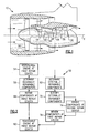
- Figure 1 schematically illustrates an example gas turbine engine 10 including (in serial flow communication) a fan section 14, a low pressure compressor 18, a high pressure compressor 22, a combustor 26, a high pressure turbine 30, and a low pressure turbine 34.
- the gas turbine engine 10 is circumferentially disposed about an engine centerline X.
- the compressors 18, 22 pressurize air that the fan section 14 pulls into the gas turbine engine 10. Pressurized air is then mixed with fuel and burned in the combustor 26. Hot combustion gases generated within the combustor 26 flow through high and low pressure turbines 30, 34, which extract energy from the hot combustion gases. The turbines 30, 34 utilize the extracted energy to power the high pressure compressor 22 and the low pressure compressor 18 through shafts 38,42.
- an example reverse engineering method 50 includes disassembling the gas turbine engine 10 at a first repair center at 54 after the first repair center assumes control of components within the gas turbine engine 10.
- repair centers often coordinate modifications, service, and repair of various types of gas turbine engines. Often, one or more manufacturers that produce engine 10 components also own or manage the repair center.
- the method is used to reverse engineer components within the gas turbine engine 10.
- the method 50 would extend to other engines or assemblies for any application.
- Disassembly separates components of the gas turbine engine 10 into a group of internally repairable components at 58 and a group of externally repairable components at 62.
- the internally repairable components at 58 may be retained for modification.
- the internally repairable components at 58 are distributed to a different company for modification. Disassembly often generates revenue for the repair center as owners of the engine 10 compensate the repair center for disassembling the engine 10.
- Example criteria used when determining the internally repairable components at 58 includes determining whether a component can be modified, serviced, or repaired at the first repair center, or estimating whether the cost of modifying, servicing, or repairing a component at the first engine center would exceed a threshold value.
- the low pressure compressor 18 is an internally repairable component at 58. Accordingly, modifications and repairs to the low pressure compressor 18 are made at the first repair center at 66. Example modifications and repairs include replacing worn blade tips within the low pressure compressor 18.
- the externally repairable components include the high pressure turbine 30.
- the first repair center may lack knowledge to profitably repair the high pressure turbine 30 as a manufacturer of the high pressure turbine 30 was not associated with the first repair center, for example. Lacking such knowledge results in lost revenue for the first repair center.
- Figure 3 illustrates an example database 100 used for recording identification information for the component and for compiling data to identify the externally repairable components.
- the example database 100 includes a part number 104, a serial number 108, and a distress code 112, which corresponds to a key detailing a needed repair. For example, if the database 100 notes "3" as the distress code 112, the key would indicate that the needed repair is an outwardly bulging or inward collapsing airfoil.
- a user of the method 50 would know how to associate particular distress codes 112 with certain repairs. The convention for associating the distress code 112 with the repair is developed by the user in one example.
- the database also links to a recorded photograph 120 for identifying the externally repairable components, as shown in Figure 4 .
- the photographed component corresponds to the appropriate part number 104 within database 100 in a known manner, such as by a hyperlink connection for example.
- the photograph 120 provides visual detail relating to the area needing repair 124. Recording information about the at least one potential repair may utilize comparisons between the eventual repaired component and the photograph 120.
- the externally repairable components move to a second repair center at 74. Once repaired, the externally repairable components return to the first repair center for evaluation and review at 78. Accordingly, after assuming control of the engine at 54, the first repair center surrenders control of the externally repairable component to the second repair center at 74. The first repair center then reassumes control of the externally repairable components after repair at the second repair center at 78. Evaluations of the repairs may take place at the first repair center.
- the database 100 ( Figures 3 and 4 ) facilitates evaluating and reviewing the newly repaired part because the information in the database can be compared to the repaired part, including the photographed part prior to repair. Evaluation and review at 78 may include noting repair techniques utilized by the second repair center. Destructive and nondestructive testing may help analyze such techniques.
- Evaluation and review of repairs at 78 may result in altered repair procedures by the manufacture associated with the first repair center, which potentially increases the number of repairable components at 58 for that manufacturer.
- altered repaired procedures may change the criteria used to determine the internally repairable components at 58.
- Future repair procedures may involve retaining more internally repairable components at 58 based upon reviewing the components at 78 after modification. The identification information facilitates the review. More internally repairable components at 58 increases revenue for the first repair center.
- Future procedures, repairs or other modifications at 74 can be altered based upon reviewing the components at 78 after modification. In one example, based upon reviewing the components at 78, more components may be retained by the first repair center in future methods. In another example, repair or modification procedures are altered at the first repair center based upon reviewing the components at 78.
- both the internally repairable components and the externally reparable components reviewed are reassembled within the within the engine at 82 at the first repair center.
Landscapes
- Engineering & Computer Science (AREA)
- General Engineering & Computer Science (AREA)
- Mechanical Engineering (AREA)
- Manufacturing & Machinery (AREA)
- Quality & Reliability (AREA)
- Physics & Mathematics (AREA)
- General Physics & Mathematics (AREA)
- Automation & Control Theory (AREA)
- Management, Administration, Business Operations System, And Electronic Commerce (AREA)
Abstract
Description
- This invention relates generally to reverse engineering component modifications, wherein identification information for a component is recorded prior to modifying the component.
- As known, reverse engineering a component facilitates developing and refining other components. Companies within some industries reverse engineer competitor components to improve their own components. In addition to the overall component design, reverse engineering often helps improve component manufacturing systems and processes, for example. Although many companies find reverse engineering beneficial, reverse engineering can be expensive and time consuming. Expending too many resources reverse engineering may negate some of the benefits.
- Companies within some industries, such as the aerospace industry, manufacture components that require periodic service, repair, or both. Gas turbine engines and other systems used within these industries often include many different components from many different companies.
- Initially developing and manufacturing the components may result in particular knowledge that is useful when servicing and repairing the components. Thus, servicing and repairing systems typically involves distributing components within the system to the many different companies for service and repair. The component developing and manufacturing company is often also the component servicing and repairing company.
- An example method of reverse engineering component modifications includes recording identification information for components and distributing a portion of the components for modification. The method receives the components after modification and reviews the components using the identification information.
- The example method of reverse engineering a component repair may include assuming control of a component, recording identification information for the component, and surrendering control of the component for a repair. The method then reassumes control of the component and evaluates the repair.
- The example method of reverse engineering competitor repairs may also include identifying at least one potential repair on a part, recording information about the potential repair, and relying on a competitor to repair the potential repair. The method reviews the repaired part using the information.
- The various features and advantages of this invention will become apparent to those skilled in the art from the following detailed description of an embodiment of the invention. The drawings accompanying the detailed description can be briefly described as follows:
-
Figure 1 shows a schematic sectional view of an example gas turbine engine; -
Figure 2 shows the flow of an example method for reverse engineering components of theFigure 1 engine; -
Figure 3 shows an example database for identifying components using theFigure 2 method; and -
Figure 4 shows an example repair identified using theFigure 2 method. -
Figure 1 schematically illustrates an examplegas turbine engine 10 including (in serial flow communication) afan section 14, alow pressure compressor 18, ahigh pressure compressor 22, acombustor 26, ahigh pressure turbine 30, and alow pressure turbine 34. Thegas turbine engine 10 is circumferentially disposed about an engine centerline X. - During operation, the
compressors fan section 14 pulls into thegas turbine engine 10. Pressurized air is then mixed with fuel and burned in thecombustor 26. Hot combustion gases generated within thecombustor 26 flow through high andlow pressure turbines turbines high pressure compressor 22 and thelow pressure compressor 18 throughshafts - Referring now to
Figure 2 with continuing reference toFigure 1 , the flow of an examplereverse engineering method 50 includes disassembling thegas turbine engine 10 at a first repair center at 54 after the first repair center assumes control of components within thegas turbine engine 10. As known, repair centers often coordinate modifications, service, and repair of various types of gas turbine engines. Often, one or more manufacturers that produceengine 10 components also own or manage the repair center. - In this example, the method is used to reverse engineer components within the
gas turbine engine 10. However, those skilled in the art and having the benefit of this description will understand that themethod 50 would extend to other engines or assemblies for any application. - Disassembly separates components of the
gas turbine engine 10 into a group of internally repairable components at 58 and a group of externally repairable components at 62. The internally repairable components at 58 may be retained for modification. In another example, the internally repairable components at 58 are distributed to a different company for modification. Disassembly often generates revenue for the repair center as owners of theengine 10 compensate the repair center for disassembling theengine 10. - Example criteria used when determining the internally repairable components at 58 includes determining whether a component can be modified, serviced, or repaired at the first repair center, or estimating whether the cost of modifying, servicing, or repairing a component at the first engine center would exceed a threshold value.
- In this example, the
low pressure compressor 18 is an internally repairable component at 58. Accordingly, modifications and repairs to thelow pressure compressor 18 are made at the first repair center at 66. Example modifications and repairs include replacing worn blade tips within thelow pressure compressor 18. - Because repairing or otherwise modifying components of the
engine 10 generates revenue for the repair center, many repair centers desire to repair as many components as possible at the repair center. - In this example, the externally repairable components include the
high pressure turbine 30. The first repair center may lack knowledge to profitably repair thehigh pressure turbine 30 as a manufacturer of thehigh pressure turbine 30 was not associated with the first repair center, for example. Lacking such knowledge results in lost revenue for the first repair center. - After determining the externally repairable components at 62, the
method 50 identifies those components at 70.Figure 3 illustrates anexample database 100 used for recording identification information for the component and for compiling data to identify the externally repairable components. As shown, theexample database 100 includes apart number 104, a serial number 108, and adistress code 112, which corresponds to a key detailing a needed repair. For example, if thedatabase 100 notes "3" as thedistress code 112, the key would indicate that the needed repair is an outwardly bulging or inward collapsing airfoil. A user of themethod 50 would know how to associateparticular distress codes 112 with certain repairs. The convention for associating thedistress code 112 with the repair is developed by the user in one example. - The database also links to a recorded
photograph 120 for identifying the externally repairable components, as shown inFigure 4 . The photographed component corresponds to theappropriate part number 104 withindatabase 100 in a known manner, such as by a hyperlink connection for example. Thephotograph 120 provides visual detail relating to thearea needing repair 124. Recording information about the at least one potential repair may utilize comparisons between the eventual repaired component and thephotograph 120. - Referring again to
Figures 1 and 2 , the externally repairable components move to a second repair center at 74. Once repaired, the externally repairable components return to the first repair center for evaluation and review at 78. Accordingly, after assuming control of the engine at 54, the first repair center surrenders control of the externally repairable component to the second repair center at 74. The first repair center then reassumes control of the externally repairable components after repair at the second repair center at 78. Evaluations of the repairs may take place at the first repair center. The database 100 (Figures 3 and 4 ) facilitates evaluating and reviewing the newly repaired part because the information in the database can be compared to the repaired part, including the photographed part prior to repair. Evaluation and review at 78 may include noting repair techniques utilized by the second repair center. Destructive and nondestructive testing may help analyze such techniques. - Evaluation and review of repairs at 78 may result in altered repair procedures by the manufacture associated with the first repair center, which potentially increases the number of repairable components at 58 for that manufacturer. As an example, altered repaired procedures may change the criteria used to determine the internally repairable components at 58. Future repair procedures may involve retaining more internally repairable components at 58 based upon reviewing the components at 78 after modification. The identification information facilitates the review. More internally repairable components at 58 increases revenue for the first repair center. Future procedures, repairs or other modifications at 74 can be altered based upon reviewing the components at 78 after modification. In one example, based upon reviewing the components at 78, more components may be retained by the first repair center in future methods. In another example, repair or modification procedures are altered at the first repair center based upon reviewing the components at 78.
- After review, both the internally repairable components and the externally reparable components reviewed are reassembled within the within the engine at 82 at the first repair center.
- Although a preferred embodiment of this invention has been disclosed, a worker of ordinary skill in this art would recognize that certain modifications would come within the scope of this invention. For that reason, the following claims should be studied to determine the true scope and content of this invention.
Claims (15)
- A method of reverse engineering component modifications, comprising(a) recording identification information for a plurality of components;(b) distributing a first portion of the plurality of components for modification;(c) receiving the first portion of the plurality of components after modification; and(d) reviewing the first portion of the plurality of components after modification using the identification information.
- The method of claim 1, including the step of:retaining a second portion of the plurality of components for modification.
- The method of claim 1 or 2, including the step of:repeating steps (a) through (c) and retaining types of components that would previously have been in the first portion in the second portion based on a prior said step (d).
- The method of claim 2 or 3, including the step of:(f) altering modifications to the second portion of the plurality of components based on said step (d).
- The method of any preceding claim, wherein said step (b) includes distributing the first portion of the plurality of components to a different company for modification.
- The method of any preceding claim, wherein the identification information includes at least one of a photograph (120), a part number (104), and a serial number (108).
- The method of any preceding claim, wherein the modification of step (b) comprises a repair.
- The method of any preceding claim, wherein said step (d) includes at least one of destructive testing and nondestructive testing.
- A method of reverse engineering a component repair, comprising(a) assuming control of a component;(b) recording identification information for the component;(c) surrendering control of the component for a repair;(d) reassuming control of component; and(e) evaluating the repair.
- The method of claim 9, including the step of:retaining control of or altering a repair to another component for repair based on said step (e).
- The method of any preceding claim, wherein the component or components comprises a gas turbine engine component or components.
- A method of reverse engineering competitor repairs, comprising:(a) identifying at least one potential repair on at least one part;(b) recording information about the at least one potential repair;(c) relying on a another company to repair the at least one potential repair; and(d) reviewing the repair to the at least one part using the information.
- The method of claim 12, wherein said step (b) includes recording a photograph (120) of the at least one potential repair.
- The method of claim 13, wherein said step (b) includes comparing the repair to the photograph (120).
- The method of claim 12, 13 or 14, wherein said step (d) includes testing repairs to the component.
Applications Claiming Priority (1)
| Application Number | Priority Date | Filing Date | Title |
|---|---|---|---|
| US12/014,971 US20090178278A1 (en) | 2008-01-16 | 2008-01-16 | Method of reverse engineering |
Publications (1)
| Publication Number | Publication Date |
|---|---|
| EP2081095A1 true EP2081095A1 (en) | 2009-07-22 |
Family
ID=40568788
Family Applications (1)
| Application Number | Title | Priority Date | Filing Date |
|---|---|---|---|
| EP09250090A Withdrawn EP2081095A1 (en) | 2008-01-16 | 2009-01-14 | Method of reverse engineering |
Country Status (2)
| Country | Link |
|---|---|
| US (1) | US20090178278A1 (en) |
| EP (1) | EP2081095A1 (en) |
Cited By (1)
| Publication number | Priority date | Publication date | Assignee | Title |
|---|---|---|---|---|
| FR3115018A1 (en) * | 2020-10-08 | 2022-04-15 | Safran Aircraft Engines | Method for checking the operability of a mechanical part of a turbojet engine for aircraft |
Citations (3)
| Publication number | Priority date | Publication date | Assignee | Title |
|---|---|---|---|---|
| US20020147518A1 (en) | 2001-04-06 | 2002-10-10 | Nguyen Tri Minh | Apparatus and method for monitoring manufacturing status |
| WO2004096487A1 (en) * | 2003-04-30 | 2004-11-11 | Mtu Aero Engines Gmbh | Method for repairing and/or modifying components of a gas turbine |
| US6922601B1 (en) | 2004-03-16 | 2005-07-26 | Hitachi Global Storage Technologies Netherlands, B.V. | System for yield improvement of manufactured products |
Family Cites Families (28)
| Publication number | Priority date | Publication date | Assignee | Title |
|---|---|---|---|---|
| US4128929A (en) * | 1977-03-15 | 1978-12-12 | Demusis Ralph T | Method of restoring worn turbine components |
| US4098450A (en) * | 1977-03-17 | 1978-07-04 | General Electric Company | Superalloy article cleaning and repair method |
| US4285459A (en) * | 1979-07-31 | 1981-08-25 | Chromalloy American Corporation | High temperature braze repair of superalloys |
| US4339745A (en) * | 1980-05-14 | 1982-07-13 | General Electric Company | Optical character recognition |
| DE3274629D1 (en) * | 1981-01-12 | 1987-01-22 | Refurbished Turbine Components | Turbine blade repair |
| US5191534A (en) * | 1990-08-21 | 1993-03-02 | International Business Machines Corporation | Engineering and manufacturing change control mechanism |
| US5408412A (en) * | 1992-04-09 | 1995-04-18 | United Technologies Corporation | Engine fault diagnostic system |
| WO1994020918A1 (en) * | 1993-03-11 | 1994-09-15 | Fibercraft/Descon Engineering, Inc. | Design and engineering project management system |
| US5485390A (en) * | 1993-11-30 | 1996-01-16 | The United States Of America As Represented By The Secrectary Of The Air Force | Inductive-deductive process design for machined parts |
| US5864482A (en) * | 1996-05-06 | 1999-01-26 | Amadasoft America, Inc. | Apparatus and method for managing distributing design and manufacturing information throughout a sheet metal production facility |
| US5799293A (en) * | 1996-11-04 | 1998-08-25 | Ford Global Technologies, Inc. | Method for optimizing the design of a product using knowledge-based engineering techniques |
| US5758416A (en) * | 1996-12-05 | 1998-06-02 | General Electric Company | Method for repairing a turbine engine vane segment |
| US6172327B1 (en) * | 1998-07-14 | 2001-01-09 | General Electric Company | Method for laser twist welding of compressor blisk airfoils |
| US6015167A (en) * | 1998-08-14 | 2000-01-18 | United Technologies Corporation | System and method of employing a single bar code for coordinating shipping and receiving information |
| US6065344A (en) * | 1998-10-20 | 2000-05-23 | General Electric Co. | Apparatus and methods for cooling an ultrasonic inspection transducer for turbine rotor wheel repair |
| US20020007289A1 (en) * | 2000-07-11 | 2002-01-17 | Malin Mark Elliott | Method and apparatus for processing automobile repair data and statistics |
| US6909800B2 (en) * | 2000-12-15 | 2005-06-21 | United Technologies Corporation | Process and apparatus for locating coated cooling holes on turbine vanes |
| US7219043B2 (en) * | 2002-02-05 | 2007-05-15 | General Electric Company | Method and system for reverse and re-engineering parts |
| US6701615B2 (en) * | 2002-03-08 | 2004-03-09 | General Electric Company | Inspection and sorting system and method for part repair |
| CA2417074C (en) * | 2003-01-24 | 2009-07-21 | Pratt & Whitney Canada Corp. | Method and system for trend detection and analysis |
| DE10319015B4 (en) * | 2003-04-27 | 2006-04-13 | Mtu Aero Engines Gmbh | Process for the maintenance of gas turbines |
| US20050065842A1 (en) * | 2003-07-28 | 2005-03-24 | Richard Summers | System and method for coordinating product inspection, repair and product maintenance |
| DE10340827A1 (en) * | 2003-09-04 | 2005-03-31 | Rolls-Royce Deutschland Ltd & Co Kg | Repair method for a blade of a fluid flow machine |
| FR2859933B1 (en) * | 2003-09-19 | 2006-02-10 | Snecma Moteurs | METHOD FOR MANUFACTURING OR REPAIRING A MONOBLOC AUBING DISK |
| WO2008094221A1 (en) * | 2006-09-26 | 2008-08-07 | Pas Technologies Inc. | Method of repairing a stationary airfoil array directing three-dimensional flow |
| US7720649B2 (en) * | 2007-03-20 | 2010-05-18 | United Technologies Corporation | Reverse engineering method for disk and blade attachments |
| US7719434B2 (en) * | 2007-03-30 | 2010-05-18 | United Technologies Corporation | Method for identifying critical features as a function of process |
| US20090106130A1 (en) * | 2007-10-17 | 2009-04-23 | United Technologies Corp. | Systems and Methods Involving Rotable Components |
-
2008
- 2008-01-16 US US12/014,971 patent/US20090178278A1/en not_active Abandoned
-
2009
- 2009-01-14 EP EP09250090A patent/EP2081095A1/en not_active Withdrawn
Patent Citations (3)
| Publication number | Priority date | Publication date | Assignee | Title |
|---|---|---|---|---|
| US20020147518A1 (en) | 2001-04-06 | 2002-10-10 | Nguyen Tri Minh | Apparatus and method for monitoring manufacturing status |
| WO2004096487A1 (en) * | 2003-04-30 | 2004-11-11 | Mtu Aero Engines Gmbh | Method for repairing and/or modifying components of a gas turbine |
| US6922601B1 (en) | 2004-03-16 | 2005-07-26 | Hitachi Global Storage Technologies Netherlands, B.V. | System for yield improvement of manufactured products |
Cited By (1)
| Publication number | Priority date | Publication date | Assignee | Title |
|---|---|---|---|---|
| FR3115018A1 (en) * | 2020-10-08 | 2022-04-15 | Safran Aircraft Engines | Method for checking the operability of a mechanical part of a turbojet engine for aircraft |
Also Published As
| Publication number | Publication date |
|---|---|
| US20090178278A1 (en) | 2009-07-16 |
Similar Documents
| Publication | Publication Date | Title |
|---|---|---|
| CN103384859B (en) | Method and system for forecasting current maintenance operations for an aircraft engine | |
| US20090048730A1 (en) | Method and system for planning repair of an engine | |
| US6339878B1 (en) | Method of repairing an airfoil | |
| US9569397B2 (en) | Methods and systems for maintenance of turbomachinery | |
| US11447271B2 (en) | Aircraft component repair scheduling system and process | |
| US6643570B2 (en) | Aircraft engine reliability business model | |
| JP4078671B2 (en) | Plant maintenance management method | |
| EP2613019A2 (en) | Method and system for maintenance of turbomachinery | |
| US11281821B2 (en) | Aircraft component qualification system and process for target based inventory qualification | |
| US8291589B2 (en) | Method for establishing a location of an elevated stress region | |
| Abd Elhalim et al. | An efficient maintenance plan using proposed framework of rcm made simple approach | |
| EP3719256B1 (en) | Aircraft component repair system and process | |
| US11755791B2 (en) | Aircraft component qualification system and process | |
| CN109791567B (en) | Method and system for recording endoscopic examination data | |
| EP2081095A1 (en) | Method of reverse engineering | |
| Stock et al. | Going back in time to improve design: the elemental function-failure design method | |
| US20140053403A1 (en) | Method for extending an original service life of gas turbine components | |
| JPH11141352A (en) | Apparatus and method for maintenance management of gas turbine hot parts | |
| Houck et al. | A fully coupled aero, thermal, and structural lifetime model for root cause failure analysis and robust redesign of an industrial f class gas turbine blade | |
| JPH10176546A (en) | Gas turbine high temperature component life extension method and apparatus | |
| US20220357229A1 (en) | Methods of identifying unbalance of engine rotors based on engine vibration | |
| EP4650569A2 (en) | Process of preparing a vane ring | |
| JPH04265425A (en) | Using limit estimating device for part of gas turbine | |
| Konoplianchenko et al. | Feature of heavy-duty gas turbine compressor reengineering | |
| Fitzgerald et al. | Cost-Benefit Analysis (CBA) of the Total Integrated Engine Revitalization (TIGER) Condition-Based Overhaul (CBO) Process for the M1 Abrams AGT 1500 Turbine Engine at the Army Depot Level of Maintenance |
Legal Events
| Date | Code | Title | Description |
|---|---|---|---|
| PUAI | Public reference made under article 153(3) epc to a published international application that has entered the european phase |
Free format text: ORIGINAL CODE: 0009012 |
|
| AK | Designated contracting states |
Kind code of ref document: A1 Designated state(s): AT BE BG CH CY CZ DE DK EE ES FI FR GB GR HR HU IE IS IT LI LT LU LV MC MK MT NL NO PL PT RO SE SI SK TR |
|
| AX | Request for extension of the european patent |
Extension state: AL BA RS |
|
| 17P | Request for examination filed |
Effective date: 20090817 |
|
| 17Q | First examination report despatched |
Effective date: 20090924 |
|
| AKX | Designation fees paid |
Designated state(s): DE GB |
|
| STAA | Information on the status of an ep patent application or granted ep patent |
Free format text: STATUS: THE APPLICATION HAS BEEN WITHDRAWN |
|
| 18W | Application withdrawn |
Effective date: 20120801 |