EP2080940A1 - Face seal for gas turbine engine - Google Patents
Face seal for gas turbine engine Download PDFInfo
- Publication number
- EP2080940A1 EP2080940A1 EP09250079A EP09250079A EP2080940A1 EP 2080940 A1 EP2080940 A1 EP 2080940A1 EP 09250079 A EP09250079 A EP 09250079A EP 09250079 A EP09250079 A EP 09250079A EP 2080940 A1 EP2080940 A1 EP 2080940A1
- Authority
- EP
- European Patent Office
- Prior art keywords
- seal
- face
- outer diameter
- inner diameter
- ratio
- Prior art date
- Legal status (The legal status is an assumption and is not a legal conclusion. Google has not performed a legal analysis and makes no representation as to the accuracy of the status listed.)
- Granted
Links
Images
Classifications
-
- F—MECHANICAL ENGINEERING; LIGHTING; HEATING; WEAPONS; BLASTING
- F16—ENGINEERING ELEMENTS AND UNITS; GENERAL MEASURES FOR PRODUCING AND MAINTAINING EFFECTIVE FUNCTIONING OF MACHINES OR INSTALLATIONS; THERMAL INSULATION IN GENERAL
- F16J—PISTONS; CYLINDERS; SEALINGS
- F16J15/00—Sealings
- F16J15/16—Sealings between relatively-moving surfaces
- F16J15/34—Sealings between relatively-moving surfaces with slip-ring pressed against a more or less radial face on one member
- F16J15/3404—Sealings between relatively-moving surfaces with slip-ring pressed against a more or less radial face on one member and characterised by parts or details relating to lubrication, cooling or venting of the seal
-
- F—MECHANICAL ENGINEERING; LIGHTING; HEATING; WEAPONS; BLASTING
- F16—ENGINEERING ELEMENTS AND UNITS; GENERAL MEASURES FOR PRODUCING AND MAINTAINING EFFECTIVE FUNCTIONING OF MACHINES OR INSTALLATIONS; THERMAL INSULATION IN GENERAL
- F16J—PISTONS; CYLINDERS; SEALINGS
- F16J15/00—Sealings
- F16J15/16—Sealings between relatively-moving surfaces
- F16J15/34—Sealings between relatively-moving surfaces with slip-ring pressed against a more or less radial face on one member
- F16J15/3464—Mounting of the seal
- F16J15/3468—Means for controlling the deformations of the contacting faces
Definitions
- This disclosure relates to a face seal for a gas turbine engine.
- a face seal that is installed within an engine bearing compartment extends between first and second seal end faces.
- One of the seal end faces contacts a rotating seal face plate.
- the seal face plate is mounted for rotation with a rotor shaft.
- the end face that contacts the seal face plate is referred to as the "nose.”
- a face seal for a gas turbine engine comprises a seal body that has a contact face to engage a rotating surface.
- the contact face is defined as an area extending radially between an inner diameter of the seal body and an outer diameter of the seal body at one seal end.
- the ratio of the outer diameter to the inner diameter is at least 1.054.
- a seal face plate is supported for rotation relative to a non-rotating engine structure.
- the seal body has a central bore extending between first and second seal end faces.
- One of the first and second seal end faces comprises the contact face that engages the seal face plate.
- a resilient member exerts a load against the other of the first and second seal end faces to press the contact face against the seal face plate.
- Figure 1 illustrates selected portions of an example gas turbine engine 10, such as a turbofan gas turbine engine used for propulsion.
- the turbine engine 10 is circumferentially disposed about an engine centerline 12.
- the turbine engine 10 includes a fan 14, a compressor section 16, a combustion section 18, and a turbine section 20.
- the combustion section 18 and the turbine section 20 include corresponding blades 22 and vanes 24.
- air compressed in the compressor section 16 is mixed with fuel and burned in the combustion section 18 to produce hot gasses that are expanded in the turbine section 20.
- Figure 1 is a somewhat schematic presentation for illustrative purposes only and is not a limitation on the disclosed examples. Additionally, there are various types of gas turbine engines, many of which could benefit from the examples disclosed herein and are not limited to the designs shown.
- a gas turbine engine may contain a reduction gearbox disposed between the turbine section 20 and the fan 14, allowing the fan 14 to turn at a different speed than the turbine.
- Figure 2 illustrates a rotating component 30 that is rotatable about an axis defined by the engine centerline 12 ( Figure 1 ).
- a seal face plate 32 also mounted for rotation about the axis.
- a bearing 34 supports the rotating component 30 for rotation relative to a non-rotating engine structure 36.
- the seal face plate 32 has a fore face 38 that engages an inner race 40 of the bearing 34 and an aft face 42 that faces a high pressure area 44 of the gas turbine engine 10.
- a face seal 50 is positioned within this high pressure area 44 and includes a first seal end face 52 that engages the aft face 42 of the seal face plate 32 and a second seal end face 54 that faces opposite of the first seal end face 52. It should be understood that only the upper cross-section of bearing 34, seal face plate 32, and face seal 50 are shown in Figure 2 , with the lower cross-section being similarly configured to that of the upper cross-section as these components extend around the axis.
- the face seal 50 includes a seal body 56 with a central bore 58 that surrounds the axis.
- the face seal 50 is made from a carbon based material as known.
- the seal body 56 extends axially between the first 52 and second 54 seal end faces in a direction that is generally parallel to the axis.
- a resilient member such as a load spring 60 for example, is used to exert a spring force against the second seal end face 54.
- the load spring 60 is supported by a non-rotating component 62 that has one portion that is spaced axially aft of the second seal end face 54 and another portion which extends into the central bore 58.
- the load spring 60 applies an axial spring force to push the first seal end face 52 into direct contact with the aft face 42 of the seal face plate 32.
- the first seal end face 52 comprises a contact face 68 ( Figure 3 ) that engages a rotating component, i.e. the seal face plate 32.
- the contact face 68 is defined as a nose area extending radially between an inner diameter D1 of the seal body 56 and an outer diameter D2 of the seal body 56.
- the ratio of the outer diameter D2 to the inner diameter D 1 is at least 1.054. In one example, the ratio is greater than 1.060. In another example, the ratio is between 1.060 and 1.071.
- the inner diameter D1 of the seal body 56 is less than 5.734 inches (14.564 centimeters) and the outer diameter is greater than 6.038 inches (15.337 centimeters).
- the contact area between the face seal 50 and the seal face plate 32 has increased by approximately 33% compared to prior configurations.
- This contact area increase of approximately 33% impacts the tribology of corresponding mating surfaces of the face seal 50 and the seal face plate 32 such that the resulting carbon wear performance is greatly improved by providing a significant reduction in the seal face wear rate.
Landscapes
- Engineering & Computer Science (AREA)
- General Engineering & Computer Science (AREA)
- Mechanical Engineering (AREA)
- Mechanical Sealing (AREA)
- Sealing Devices (AREA)
Abstract
Description
- This disclosure relates to a face seal for a gas turbine engine.
- A face seal that is installed within an engine bearing compartment extends between first and second seal end faces. One of the seal end faces contacts a rotating seal face plate. The seal face plate is mounted for rotation with a rotor shaft. The end face that contacts the seal face plate is referred to as the "nose."
- Future aircraft engine products require cycles that have significantly higher rotor speeds than traditionally defined cycles. Higher rotor speeds accordingly result in higher bearing compartment seal rubbing speeds. Traditionally, to reduce friction and wear, the width of the nose has been minimized as much as possible. In one known configuration, the industry calls for nose widths to be .150 inches (.381 centimeters) or less.
- In the past, improved carbon materials have been used to increase seal wear life. However, current carbon materials do not provide the desired wear life for future higher rotor speed requirements.
- Accordingly, there is a need to provide an improved face seal that can provide a desired seal wear life at high rotor speeds, as well as addressing the other short comings discussed above.
- A face seal for a gas turbine engine comprises a seal body that has a contact face to engage a rotating surface. The contact face is defined as an area extending radially between an inner diameter of the seal body and an outer diameter of the seal body at one seal end. The ratio of the outer diameter to the inner diameter is at least 1.054.
- In one example, a seal face plate is supported for rotation relative to a non-rotating engine structure. The seal body has a central bore extending between first and second seal end faces. One of the first and second seal end faces comprises the contact face that engages the seal face plate. A resilient member exerts a load against the other of the first and second seal end faces to press the contact face against the seal face plate.
- The various features and advantages of this invention will become apparent to those skilled in the art from the following detailed description of the currently preferred embodiment. The drawings that accompany the detailed description can be briefly described as follows.
-
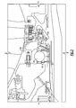
Figure 1 is a highly schematic view of a cross-section of a gas turbine engine. -
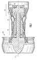
Figure 2 is a schematic view of a partial cross-section of a shaft, bearing, and face seal. -
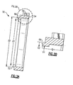
Figure 3A is a cross-sectional view of the face seal. -
Figure 3B is a magnified view of a portion of the face seal as indicated inFigure 3A . -
Figure 1 illustrates selected portions of an examplegas turbine engine 10, such as a turbofan gas turbine engine used for propulsion. In this example, theturbine engine 10 is circumferentially disposed about anengine centerline 12. Theturbine engine 10 includes afan 14, acompressor section 16, acombustion section 18, and aturbine section 20. Thecombustion section 18 and theturbine section 20 includecorresponding blades 22 andvanes 24. As is known, air compressed in thecompressor section 16 is mixed with fuel and burned in thecombustion section 18 to produce hot gasses that are expanded in theturbine section 20. -
Figure 1 is a somewhat schematic presentation for illustrative purposes only and is not a limitation on the disclosed examples. Additionally, there are various types of gas turbine engines, many of which could benefit from the examples disclosed herein and are not limited to the designs shown. For example, a gas turbine engine may contain a reduction gearbox disposed between theturbine section 20 and thefan 14, allowing thefan 14 to turn at a different speed than the turbine. -
Figure 2 illustrates arotating component 30 that is rotatable about an axis defined by the engine centerline 12 (Figure 1 ). A seal face plate 32 also mounted for rotation about the axis. Abearing 34 supports the rotatingcomponent 30 for rotation relative to anon-rotating engine structure 36. The seal face plate 32 has afore face 38 that engages aninner race 40 of the bearing 34 and an aft face 42 that faces a high pressure area 44 of thegas turbine engine 10. - A
face seal 50 is positioned within this high pressure area 44 and includes a firstseal end face 52 that engages the aft face 42 of the seal face plate 32 and a secondseal end face 54 that faces opposite of the firstseal end face 52. It should be understood that only the upper cross-section ofbearing 34, seal face plate 32, andface seal 50 are shown inFigure 2 , with the lower cross-section being similarly configured to that of the upper cross-section as these components extend around the axis. - The
face seal 50 includes aseal body 56 with acentral bore 58 that surrounds the axis. Theface seal 50 is made from a carbon based material as known. Theseal body 56 extends axially between the first 52 and second 54 seal end faces in a direction that is generally parallel to the axis. A resilient member, such as aload spring 60 for example, is used to exert a spring force against the secondseal end face 54. Theload spring 60 is supported by anon-rotating component 62 that has one portion that is spaced axially aft of the secondseal end face 54 and another portion which extends into thecentral bore 58. Theload spring 60 applies an axial spring force to push the firstseal end face 52 into direct contact with the aft face 42 of the seal face plate 32. - As such, the first
seal end face 52 comprises a contact face 68 (Figure 3 ) that engages a rotating component, i.e. the seal face plate 32. Thecontact face 68 is defined as a nose area extending radially between an inner diameter D1 of theseal body 56 and an outer diameter D2 of theseal body 56. - The ratio of the outer diameter D2 to the inner diameter D 1 is at least 1.054. In one example, the ratio is greater than 1.060. In another example, the ratio is between 1.060 and 1.071.
- In one example, the inner diameter D1 of the
seal body 56 is less than 5.734 inches (14.564 centimeters) and the outer diameter is greater than 6.038 inches (15.337 centimeters). - As such, the contact area between the
face seal 50 and the seal face plate 32 has increased by approximately 33% compared to prior configurations. This contact area increase of approximately 33% impacts the tribology of corresponding mating surfaces of theface seal 50 and the seal face plate 32 such that the resulting carbon wear performance is greatly improved by providing a significant reduction in the seal face wear rate. - High speed seal testing has been conducted for applications up to 535 feet per second (163 meters per second) of seal rub velocity with seals having the 33% increased contact area. The tests show that the decrease in seal face contact stress for these seals results in a seal wear life that improves by a factor of 10. As such, a significant increase in seal wear life is provided with minimal cost impact.
- Although a combination of features is shown in the illustrated examples, not all of them need to be combined to realize the benefits of various embodiments of this disclosure. In other words, a system designed according to an embodiment of this disclosure will not necessarily include all of the features shown in any one of the Figures or all of the portions schematically shown in the Figures. Moreover, selected features of one example embodiment may be combined with selected features of other example embodiments.
- The preceding description is exemplary rather than limiting in nature. Variations and modifications to the disclosed examples may become apparent to those skilled in the art that do not necessarily depart from the essence of this disclosure. The scope of legal protection given to this disclosure can only be determined by studying the following claims.
Claims (10)
- A face seal for a gas turbine engine comprising:a seal body (56) having a contact face (52) to engage a rotating surface (42) wherein said contact face (52) is defined as an area extending radially between an inner diameter (D1) of said seal body (56) and an outer diameter (D2) of said seal body (56) at one seal end, and wherein a ratio of said outer diameter (D2) to said inner diameter (D1) is at least 1.054.
- The face seal according to claim 1 wherein said ratio is greater than 1.060.
- The face seal according to claim 2 wherein said ratio is between 1.060 and 1.071.
- The face seal according to claim 1, 2 or 3 wherein said inner diameter (D1) is less than 5.734 inches (14.564 centimeters) and said outer diameter (D2) is greater than 6.038 inches (15.337 centimeters).
- The face seal according to any preceding claim wherein said seal body (56) is comprised of a carbon based material.
- A face seal assembly for a gas turbine engine comprising:a seal face plate (32) supported for rotation relative to a non-rotating engine structure (36);a seal body (56) having a central bore extend between first (52) and second (54) seal end faces wherein one of said first (52) and said second (54) seal end faces comprises a contact (52) face that engages said seal face plate (32), with said contact face (52) being defined as an area extending radially between an inner diameter (D1) of said seal body (56) and an outer diameter (D2) of said seal body (56), and wherein a ratio of said outer diameter (D2) to said inner diameter (D1) is at least 1.054; anda resilient member exerting a load against the other of said first (52) and second (54) seal end faces to press said contact face (52) against said seal face plate (32).
- The face seal assembly according to claim 6 wherein said ratio is greater than 1.060.
- The face seal assembly according to claim 6 or 7 wherein said ratio is between 1.060 and 1.071.
- The face seal assembly according to claim 6, 7 or 8 wherein said inner diameter (D1) is less than 5.734 inches (14.564 centimeters) and said outer diameter (D2) is greater than 6.038 inches (15.337 centimeters).
- The face seal assembly according to any of claims 6 to 8, wherein said seal body (56) is comprised of a carbon based material.
Applications Claiming Priority (1)
| Application Number | Priority Date | Filing Date | Title |
|---|---|---|---|
| US12/015,715 US7946590B2 (en) | 2008-01-17 | 2008-01-17 | Face seal for gas turbine engine |
Publications (2)
| Publication Number | Publication Date |
|---|---|
| EP2080940A1 true EP2080940A1 (en) | 2009-07-22 |
| EP2080940B1 EP2080940B1 (en) | 2012-10-17 |
Family
ID=40568736
Family Applications (1)
| Application Number | Title | Priority Date | Filing Date |
|---|---|---|---|
| EP09250079A Active EP2080940B1 (en) | 2008-01-17 | 2009-01-14 | Face seal for gas turbine engine |
Country Status (2)
| Country | Link |
|---|---|
| US (1) | US7946590B2 (en) |
| EP (1) | EP2080940B1 (en) |
Cited By (1)
| Publication number | Priority date | Publication date | Assignee | Title |
|---|---|---|---|---|
| EP2256383A3 (en) * | 2009-05-27 | 2013-04-03 | United Technologies Corporation | Face seal for gas turbine engine |
Families Citing this family (16)
| Publication number | Priority date | Publication date | Assignee | Title |
|---|---|---|---|---|
| US8821113B2 (en) | 2010-12-21 | 2014-09-02 | Hamilton Sundstrand Corporation | Air cycle machine seal land |
| US8770928B2 (en) | 2010-12-21 | 2014-07-08 | Hamilton Sundstrand Corporation | Air cycle machine seal plate and seal land |
| CN102913621B (en) | 2011-08-05 | 2015-11-25 | 哈米尔顿森德斯特兰德公司 | Carbon Sealing O type ring cavity size is arranged |
| US9316119B2 (en) | 2011-09-15 | 2016-04-19 | United Technologies Corporation | Turbomachine secondary seal assembly |
| US8845282B2 (en) * | 2011-09-28 | 2014-09-30 | United Technologies Corporation | Seal plate with cooling passage |
| US8616777B1 (en) | 2012-11-16 | 2013-12-31 | Pratt & Whitney Canada Corp. | Bearing assembly with inner ring |
| WO2014107161A1 (en) * | 2013-01-04 | 2014-07-10 | United Technologies Corporation | Seal assembly for arranging between a stator and a rotor |
| EP3524797A3 (en) | 2013-10-22 | 2019-10-16 | United Technologies Corporation | Piloted retaining plate for a face seal arrangement |
| US10287981B2 (en) | 2014-03-31 | 2019-05-14 | United Technologies Corporation | Seal assembly with cooling feature |
| US9926797B2 (en) | 2015-01-22 | 2018-03-27 | United Technologies Corporation | Flange trapped seal configuration |
| US10161256B2 (en) | 2015-01-22 | 2018-12-25 | Untied Technologies Corporation | Seal with backup seal |
| US10215098B2 (en) | 2015-01-22 | 2019-02-26 | United Technologies Corporation | Bearing compartment seal |
| US9909438B2 (en) | 2016-04-12 | 2018-03-06 | United Technologies Corporation | Hydrodynamic carbon face seal pressure booster |
| US10145255B2 (en) * | 2017-01-13 | 2018-12-04 | United Technologies Corporation | Constant speed 2 piece ring seal arrangement |
| US11035253B2 (en) | 2019-02-05 | 2021-06-15 | Raytheon Technologies Corporation | Face seal with damper |
| US10975723B2 (en) | 2019-02-26 | 2021-04-13 | Raytheon Technologies Corporation | Gas turbine engine including seal plate providing increased cooling adjacent contact area |
Citations (3)
| Publication number | Priority date | Publication date | Assignee | Title |
|---|---|---|---|---|
| US4026564A (en) | 1975-12-23 | 1977-05-31 | Atomic Energy Of Canada Limited | Rotary shaft face seal |
| GB2285101A (en) | 1993-12-23 | 1995-06-28 | Crane John Uk Ltd | Seal for use with liquids |
| US5501471A (en) | 1992-06-11 | 1996-03-26 | Nippon Pillar Packing Co., Ltd. | Mechanical seal with blade-like sealing end |
Family Cites Families (14)
| Publication number | Priority date | Publication date | Assignee | Title |
|---|---|---|---|---|
| US3915521A (en) * | 1974-09-30 | 1975-10-28 | United Technologies Corp | Lubricated radial bearing assembly |
| JPS5351965Y2 (en) * | 1975-03-27 | 1978-12-12 | ||
| US4407512A (en) * | 1976-01-02 | 1983-10-04 | John Crane-Houdaille, Inc. | High pressure rotary mechanical seal |
| US4142731A (en) * | 1977-05-13 | 1979-03-06 | Tsentralny Nauchno-Issledovatelsky Avtomobilny I Avtomotorny Institut Nami | End-type seal |
| US4406459A (en) * | 1982-06-18 | 1983-09-27 | United Technologies Corporation | Oil weepage return for carbon seal plates |
| US5088890A (en) * | 1989-12-11 | 1992-02-18 | Sundstrand Corporation | Seal construction for use in a turbine engine |
| JP3555683B2 (en) * | 1992-08-11 | 2004-08-18 | ユナイテッド・テクノロジーズ・コーポレイション | Seal assembly for rotating machine |
| US5490679A (en) * | 1993-12-20 | 1996-02-13 | John Crane Inc. | Seal ring design |
| US6131914A (en) * | 1996-08-30 | 2000-10-17 | United Technologies Corporation | Gas turbine engine bearing compartment seal |
| US6676369B2 (en) * | 2002-03-26 | 2004-01-13 | General Electric Company | Aspirating face seal with axially extending seal teeth |
| US6758477B2 (en) * | 2002-03-26 | 2004-07-06 | General Electric Company | Aspirating face seal with axially biasing one piece annular spring |
| US20050206088A1 (en) * | 2004-03-16 | 2005-09-22 | Anderson James H | Bearing seal with backup device |
| US7225626B2 (en) * | 2004-08-16 | 2007-06-05 | Honeywell International, Inc. | Thermal management of a gas turbine bearing compartment utilizing separate lubrication and cooling circuits |
| US7410341B2 (en) * | 2005-06-22 | 2008-08-12 | Honeywell International, Inc. | Internally-cooled seal housing for turbine engine |
-
2008
- 2008-01-17 US US12/015,715 patent/US7946590B2/en active Active
-
2009
- 2009-01-14 EP EP09250079A patent/EP2080940B1/en active Active
Patent Citations (3)
| Publication number | Priority date | Publication date | Assignee | Title |
|---|---|---|---|---|
| US4026564A (en) | 1975-12-23 | 1977-05-31 | Atomic Energy Of Canada Limited | Rotary shaft face seal |
| US5501471A (en) | 1992-06-11 | 1996-03-26 | Nippon Pillar Packing Co., Ltd. | Mechanical seal with blade-like sealing end |
| GB2285101A (en) | 1993-12-23 | 1995-06-28 | Crane John Uk Ltd | Seal for use with liquids |
Cited By (1)
| Publication number | Priority date | Publication date | Assignee | Title |
|---|---|---|---|---|
| EP2256383A3 (en) * | 2009-05-27 | 2013-04-03 | United Technologies Corporation | Face seal for gas turbine engine |
Also Published As
| Publication number | Publication date |
|---|---|
| US7946590B2 (en) | 2011-05-24 |
| US20090184475A1 (en) | 2009-07-23 |
| EP2080940B1 (en) | 2012-10-17 |
Similar Documents
| Publication | Publication Date | Title |
|---|---|---|
| US7946590B2 (en) | Face seal for gas turbine engine | |
| US7984911B2 (en) | Face seal for gas turbine engine | |
| US10066496B2 (en) | Gas turbine engine and seal assembly therefore | |
| US8777229B2 (en) | Liftoff carbon seal | |
| EP3232011B1 (en) | Hydrodynamic carbon face seal pressure booster | |
| US10539034B2 (en) | Radial seal with offset relief cut | |
| US10370996B2 (en) | Floating, non-contact seal with offset build clearance for load imbalance | |
| EP2888451B1 (en) | Spring carrier and removable seal carrier | |
| EP2570612B1 (en) | Turbomachine secondary seal assembly | |
| US9022390B2 (en) | Threaded seal for a gas turbine engine | |
| EP3067579B1 (en) | Bearing arrangement for a gas turbine engine with two rolling bearings and a centring spring integral with both outer rings | |
| US9512735B2 (en) | Sliding seal | |
| US9482158B2 (en) | Turbomachine hybrid lift-off face seal | |
| US20190226585A1 (en) | Hydrodynamic Intershaft Piston Ring Seal | |
| EP3048343B1 (en) | Multi-stage inter shaft ring seal | |
| EP3048344B1 (en) | Seal housing pre-taper | |
| EP3163103B1 (en) | Bearing device and rotary machine | |
| US20180291755A1 (en) | Insulated seal seat | |
| US11933180B2 (en) | Labyrinth seal | |
| EP3841286B1 (en) | Secondary seal in a non-contact seal assembly | |
| US20150098816A1 (en) | System and method for controlling backbone bending in a gas turbine engine | |
| US20090285690A1 (en) | Axial blade slot pressure face with undercut |
Legal Events
| Date | Code | Title | Description |
|---|---|---|---|
| PUAI | Public reference made under article 153(3) epc to a published international application that has entered the european phase |
Free format text: ORIGINAL CODE: 0009012 |
|
| AK | Designated contracting states |
Kind code of ref document: A1 Designated state(s): AT BE BG CH CY CZ DE DK EE ES FI FR GB GR HR HU IE IS IT LI LT LU LV MC MK MT NL NO PL PT RO SE SI SK TR |
|
| AX | Request for extension of the european patent |
Extension state: AL BA RS |
|
| 17P | Request for examination filed |
Effective date: 20090817 |
|
| 17Q | First examination report despatched |
Effective date: 20091120 |
|
| AKX | Designation fees paid |
Designated state(s): DE GB |
|
| GRAP | Despatch of communication of intention to grant a patent |
Free format text: ORIGINAL CODE: EPIDOSNIGR1 |
|
| GRAS | Grant fee paid |
Free format text: ORIGINAL CODE: EPIDOSNIGR3 |
|
| GRAA | (expected) grant |
Free format text: ORIGINAL CODE: 0009210 |
|
| AK | Designated contracting states |
Kind code of ref document: B1 Designated state(s): DE GB |
|
| REG | Reference to a national code |
Ref country code: GB Ref legal event code: FG4D |
|
| REG | Reference to a national code |
Ref country code: DE Ref legal event code: R096 Ref document number: 602009010452 Country of ref document: DE Effective date: 20121213 |
|
| PLBE | No opposition filed within time limit |
Free format text: ORIGINAL CODE: 0009261 |
|
| STAA | Information on the status of an ep patent application or granted ep patent |
Free format text: STATUS: NO OPPOSITION FILED WITHIN TIME LIMIT |
|
| 26N | No opposition filed |
Effective date: 20130718 |
|
| REG | Reference to a national code |
Ref country code: DE Ref legal event code: R097 Ref document number: 602009010452 Country of ref document: DE Effective date: 20130718 |
|
| REG | Reference to a national code |
Ref country code: DE Ref legal event code: R082 Ref document number: 602009010452 Country of ref document: DE Representative=s name: SCHMITT-NILSON SCHRAUD WAIBEL WOHLFROM PATENTA, DE |
|
| REG | Reference to a national code |
Ref country code: DE Ref legal event code: R082 Ref document number: 602009010452 Country of ref document: DE Representative=s name: SCHMITT-NILSON SCHRAUD WAIBEL WOHLFROM PATENTA, DE Ref country code: DE Ref legal event code: R081 Ref document number: 602009010452 Country of ref document: DE Owner name: UNITED TECHNOLOGIES CORP. (N.D.GES.D. STAATES , US Free format text: FORMER OWNER: UNITED TECHNOLOGIES CORPORATION, HARTFORD, CONN., US |
|
| REG | Reference to a national code |
Ref country code: DE Ref legal event code: R081 Ref document number: 602009010452 Country of ref document: DE Owner name: RAYTHEON TECHNOLOGIES CORPORATION (N.D.GES.D.S, US Free format text: FORMER OWNER: UNITED TECHNOLOGIES CORP. (N.D.GES.D. STAATES DELAWARE), FARMINGTON, CONN., US Ref country code: DE Ref legal event code: R081 Ref document number: 602009010452 Country of ref document: DE Owner name: RTX CORPORATION (N.D.GES.D. STAATES DELAWARE),, US Free format text: FORMER OWNER: UNITED TECHNOLOGIES CORP. (N.D.GES.D. STAATES DELAWARE), FARMINGTON, CONN., US |
|
| P01 | Opt-out of the competence of the unified patent court (upc) registered |
Effective date: 20230519 |
|
| REG | Reference to a national code |
Ref country code: DE Ref legal event code: R081 Ref document number: 602009010452 Country of ref document: DE Owner name: RTX CORPORATION (N.D.GES.D. STAATES DELAWARE),, US Free format text: FORMER OWNER: RAYTHEON TECHNOLOGIES CORPORATION (N.D.GES.D.STAATES DELAWARE), ARLINGTON, VA, US |
|
| PGFP | Annual fee paid to national office [announced via postgrant information from national office to epo] |
Ref country code: GB Payment date: 20251220 Year of fee payment: 18 |
|
| PGFP | Annual fee paid to national office [announced via postgrant information from national office to epo] |
Ref country code: DE Payment date: 20251217 Year of fee payment: 18 |