EP2080903A1 - Fail-safe system for controlling wind turbines - Google Patents
Fail-safe system for controlling wind turbines Download PDFInfo
- Publication number
- EP2080903A1 EP2080903A1 EP08001065A EP08001065A EP2080903A1 EP 2080903 A1 EP2080903 A1 EP 2080903A1 EP 08001065 A EP08001065 A EP 08001065A EP 08001065 A EP08001065 A EP 08001065A EP 2080903 A1 EP2080903 A1 EP 2080903A1
- Authority
- EP
- European Patent Office
- Prior art keywords
- control unit
- network
- functions
- critical
- wind turbine
- Prior art date
- Legal status (The legal status is an assumption and is not a legal conclusion. Google has not performed a legal analysis and makes no representation as to the accuracy of the status listed.)
- Granted
Links
- 230000006870 function Effects 0.000 claims abstract description 57
- 238000013523 data management Methods 0.000 claims abstract description 6
- 238000000034 method Methods 0.000 claims description 11
- 238000004891 communication Methods 0.000 claims description 4
- 238000005259 measurement Methods 0.000 claims description 4
- 239000007787 solid Substances 0.000 claims description 4
- 230000003287 optical effect Effects 0.000 claims description 3
- 238000013500 data storage Methods 0.000 claims description 2
- 238000012546 transfer Methods 0.000 claims description 2
- 238000012545 processing Methods 0.000 description 5
- 238000012423 maintenance Methods 0.000 description 4
- 238000013459 approach Methods 0.000 description 3
- 230000015556 catabolic process Effects 0.000 description 2
- 238000006731 degradation reaction Methods 0.000 description 2
- 230000000694 effects Effects 0.000 description 2
- 230000002452 interceptive effect Effects 0.000 description 2
- 238000002955 isolation Methods 0.000 description 2
- 238000012544 monitoring process Methods 0.000 description 2
- 230000002411 adverse Effects 0.000 description 1
- 230000001010 compromised effect Effects 0.000 description 1
- 230000002950 deficient Effects 0.000 description 1
- 230000001419 dependent effect Effects 0.000 description 1
- 238000013461 design Methods 0.000 description 1
- 125000000524 functional group Chemical group 0.000 description 1
- 230000033001 locomotion Effects 0.000 description 1
- 238000000926 separation method Methods 0.000 description 1
Images
Classifications
-
- F—MECHANICAL ENGINEERING; LIGHTING; HEATING; WEAPONS; BLASTING
- F03—MACHINES OR ENGINES FOR LIQUIDS; WIND, SPRING, OR WEIGHT MOTORS; PRODUCING MECHANICAL POWER OR A REACTIVE PROPULSIVE THRUST, NOT OTHERWISE PROVIDED FOR
- F03D—WIND MOTORS
- F03D7/00—Controlling wind motors
- F03D7/02—Controlling wind motors the wind motors having rotation axis substantially parallel to the air flow entering the rotor
- F03D7/04—Automatic control; Regulation
- F03D7/042—Automatic control; Regulation by means of an electrical or electronic controller
- F03D7/047—Automatic control; Regulation by means of an electrical or electronic controller characterised by the controller architecture, e.g. multiple processors or data communications
-
- F—MECHANICAL ENGINEERING; LIGHTING; HEATING; WEAPONS; BLASTING
- F05—INDEXING SCHEMES RELATING TO ENGINES OR PUMPS IN VARIOUS SUBCLASSES OF CLASSES F01-F04
- F05B—INDEXING SCHEME RELATING TO WIND, SPRING, WEIGHT, INERTIA OR LIKE MOTORS, TO MACHINES OR ENGINES FOR LIQUIDS COVERED BY SUBCLASSES F03B, F03D AND F03G
- F05B2270/00—Control
- F05B2270/10—Purpose of the control system
- F05B2270/101—Purpose of the control system to control rotational speed (n)
- F05B2270/1011—Purpose of the control system to control rotational speed (n) to prevent overspeed
-
- F—MECHANICAL ENGINEERING; LIGHTING; HEATING; WEAPONS; BLASTING
- F05—INDEXING SCHEMES RELATING TO ENGINES OR PUMPS IN VARIOUS SUBCLASSES OF CLASSES F01-F04
- F05B—INDEXING SCHEME RELATING TO WIND, SPRING, WEIGHT, INERTIA OR LIKE MOTORS, TO MACHINES OR ENGINES FOR LIQUIDS COVERED BY SUBCLASSES F03B, F03D AND F03G
- F05B2270/00—Control
- F05B2270/10—Purpose of the control system
- F05B2270/107—Purpose of the control system to cope with emergencies
-
- Y—GENERAL TAGGING OF NEW TECHNOLOGICAL DEVELOPMENTS; GENERAL TAGGING OF CROSS-SECTIONAL TECHNOLOGIES SPANNING OVER SEVERAL SECTIONS OF THE IPC; TECHNICAL SUBJECTS COVERED BY FORMER USPC CROSS-REFERENCE ART COLLECTIONS [XRACs] AND DIGESTS
- Y02—TECHNOLOGIES OR APPLICATIONS FOR MITIGATION OR ADAPTATION AGAINST CLIMATE CHANGE
- Y02E—REDUCTION OF GREENHOUSE GAS [GHG] EMISSIONS, RELATED TO ENERGY GENERATION, TRANSMISSION OR DISTRIBUTION
- Y02E10/00—Energy generation through renewable energy sources
- Y02E10/70—Wind energy
- Y02E10/72—Wind turbines with rotation axis in wind direction
Definitions
- the invention relates to a wind turbine control system with at least a first and a second control unit coupled to each other over a first network.
- each particular component in the system is provided with a guaranteed life-time, after which the respective component is to be exchanged - the guaranteed life-time of a component being much lower than its actual life-time. While this approach provides for a very high reliability when the system is used, it requires a significant amount of maintenance, and thus, downtime. When, however, trying to reduce maintenance efforts, for instance by providing the system components with the highest possible life-time, the components need to be even further overdimensioned, so that the overall technical effort remains very high.
- signal processing means in module A may be of the same type as in module B, however, the signal processing means of module B can not take over the signal processing of module A in case module A fails.
- each of the modules associated to the various functions have to be dimensioned to provide a high life-time, resulting in high cost and technical effort.
- the invention according to claim 1 teaches a wind turbine control system with at least a first and a second control unit coupled to each other over a first network, characterized in that the first control unit is configured as a critical control unit, comprising a first set of functions comprising critical control functions for the operation of a wind turbine; the second control unit is configured as a secondary control unit, comprising a second set of functions comprising non-critical control functions and data management functions.
- each of a plurality of control modules comprises functions that are critical to the wind turbine.
- Such critical functions may comprise functions that are necessary to avoid mechanical or electrical damages to the wind turbine or elementary user interface functions for influencing the wind turbine by an operator.
- non-critical control functions By concentrating, at the same time, non-critical control functions to a second control unit, it is provided to keep the critical control unit as free as possible from computational load of non-critical processes. First, the risk of a non-critical process interfering with a critical process and thereby causing a failure of the critical control functions is thus minimized. Second, computational capacity of the critical unit, which may run on a high-reliability subsystem and thus may be more expensive, is saved. Examples of such non-critical functions that, however, produce high computational load are the logging of measurement data, or providing advanced user-interface functions such as through a web server.
- the mean time between failures of the first control unit is larger than the mean time between failures of the second control unit, thus making use of the technically efficient concentration of critical functions to the first control unit. While particularly reliable hard- and software may be used for the first unit, universal-purpose standard computing platforms, for instance for embedded systems, may be used for the second unit.
- control functions of the first set may also be redundantly included in the second set, to provide graceful degradation within the overall control system.
- the first control unit is configured to satisfy real-time conditions. This may include using a real-time operating system and using appropriate software and hardware components to provide the critical control functions.
- the first control unit can be embodied to comprise a solid-state data store and may be configured to use the solid-state data store as a mass data storage.
- Such solid-state data store may comprise a solid state disc and/or a compact flash card.
- the data management functions comprise logging and/or retrieving data collected from the first control unit.
- the second set of functions to be provided by the second control unit may comprise user interface functions, such as servicing hypertext transfer protocol requests by a web server.
- the user interface functions embodied in the second unit are more advanced and provide further data access and analysis in a conveniently accessible form.
- the second control unit may be coupled to a second network.
- a failure in the second network does not afflict communication on the first network.
- it can be embodied as an optical communication network.
- the second network can comprise a local area network and/or a wide area network and/or at least one virtual local area network.
- the first control unit is coupled to the second network as well and the critical control functions comprise providing an interface for operating the turbine, a redundant user access point is provided through which an external operator or control system can influence the wind turbine.
- the critical control functions can comprise one or more of the following functions:
- the first and/or second network may comprise a process data network
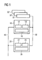
- FIG. 1 shows a schematic overview of an embodiment of the proposed wind turbine control system.
- a critical control unit 10 comprises a set of critical control functions 12, a solid state disk 14 as mass storage and operates on a real-time system platform 16 comprised in the unit.
- Critical control unit 10 is connected to secondary control unit 20 via process data network 30.
- Secondary control unit 20 comprises a set of non-critical control functions 22, a computer hard disk 24 as mass storage and a standard embedded system platform 26.
- I/O stations 32, 32', 32'' are connected to process data network 30 to communicate to critical control unit 10 and secondary control unit 20.
- These I/O stations may be different kinds of passive distributed I/O stations (e.g. standard digital and analog I/O), or intelligent units performing special functions (e.g. grid monitoring or pitch control).
- two possible custom designed units may be present among the I/O stations, namely a hub computer and a G-sensor module (accelerometer module).
- the hub computer would be present to be able to interface to the pitch system of the wind turbine's rotor.
- the G-sensor would, for example, be included on the hub computer to provide additional signals used in the pitch system. Such signals would represent motions of the wind turbine's tower.
- the G-sensor could be placed in the nacelle or the tower.
- I/O stations may be a grid measuring and controlling module, a converter complising a generator inverter and a grid inverter, etc. Both critical control unit 10 and secondary control unit 20 are further connected to external network 40.
- Critical control unit 10 performs all control functions that are critical to the operation of the turbine. This particularly comprises such functions that prevent damage to the otherwise uncontrolled turbine.
- the critical control unit runs application software that is considered to be of primary importance for wind turbine operation, performs the actual controlling via distributed I/O stations 32, 32', 32'' and possibly further distributed intelligent control units, provides a primary interface for influencing the wind turbine by an external operator or other system components over networks 30 and/or 40, provides an interface for providing measurement data (and other) to other system components over networks 30 and/or 40, and acts as a controller device (master device) in the process data network 30.
- the critical control unit uses flash-based memory 14 as a mass storage device, such as a Compact Flash-card or any type of solid state disk. Optionally, it may be equipped with a redundant array of independent disks (RAID).
- the real-time system platform 16 is based on an Intel processor with corresponding BIOS-operated main board architecture in connection with a real-time operating system such as the QNX system.
- control unit 10 is equipped with a PROFINET IRT controller. Further, an Ethernet controller located in the unit serves to connect to external network 40. Heat-generating elements in the unit are passively cooled in order to fully avoid the use of moving or rotating parts in the system.
- critical control unit 10 is enhanced by avoiding mechanical wear, and at the same time, concentrating all critical control functions in this unit while keeping it free from secondary control functions and secondary software applications, and the unit is enabled to match the real-time requirements induced by its control tasks. Due to the focus of functionality provided in this unit, its reliability can be enhanced in a particularly effective manner by using parts with greater guaranteed life time only for critical functions.
- Secondary control unit 20 uses relatively inexpensive processor and mass-storage devices (for instance, RAID), so that comparatively large calculating capacity can be provided at low cost. Secondary control unit 20 can further run a variety of secondary software applications without the risk of interfering with critical control functions, or overloading the critical control unit. In order to reduce the negative effects of vibrations in the wind turbine setting, the secondary control unit 20 can be located at the tower base of a wind turbine. As embedded platform, Windows XP Embedded can be used on a standard Intel architecture. Secondary control unit 20 can provide data management functions such as collecting data from critical control unit 10 and storing, retrieving and processing them, as well as advanced user interface functions through a web server.
- RAID mass-storage devices
- critical control unit 10 If certain critical functions of the critical control unit 10 are embodied in secondary control unit 20 as well, so that the secondary control unit can take over certain critical functions in case of failure of the critical control unit, the system provides additional fault-tolerance and graceful degradation.
- Internal network 30 is an industrial standard processing network (field bus) and is of high bandwidth, so that the life span of the network is not compromised due to bandwidth resources becoming too small. Industrial standard components used throughout the present embodiments can be maintained relatively quickly and easily. Further, the field bus system may interface to other field bus systems via bus couplers, so that a high degree of scalability is achieved. Internal network 30 provides the bandwidth to carry the total system busload while providing real-time capabilities. In configurations where critical control functions are not embodied in the secondary unit as well, for providing fault tolerant takeover, it is sufficient to only connect critical control unit 10 with the I/O stations. Where such takeover is implemented, secondary unit 20 is connected to the process network as well.
- field bus industrial standard processing network
- I/O stations 32, 32', 32'' provide interfaces with transducers and actuators in the wind turbine.
- different types of I/O stations can be used, depending on the particular needs of interfacing with the respective sensor/actor.
- External network 40 is an Ethernet network and provides external access to wind turbine control system and other components within the wind turbine.
- the external network may extend across an entire wind turbine park and can be of any network topology. Since both critical control unit 10 and secondary control unit 20 are connected to the external network, a redundant network access point is provided, so that both of the control units can always be reached, also in case one of the control units fails.
- External network can be implemented as an optical Ethernet, so that a reliable and economical connection is provided which is immune to electrical influence, such as lightning.
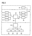
- FIG 2 shows a schematic overview of the system environment in which the embodiment is deployed. Reference numerals identical to those in figure 1 refer to identical elements. Thus, critical control unit 10, secondary control unit 20, I/O stations 32 and 32' are connected via internal process network 30, and critical control unit 10 and secondary control unit 20 both are connected to external network 40, as shown in figure 1 . Control units 10 and 20, as well as I/O station 32, are located at the wind turbine tower base, while I/O station 32' is located at the wind turbine nacelle.
- External network 40 comprises a first portion to connect the control units as well as IP Phone 52, TCM Server 54 (TCM: Wind T urbine C ondtion M onitoring Sytem), and customer units 56 and 58 with a virtual local area network (VLAN) switch 50.
- the VLAN switch serves to separate the network traffic into a number of logically independent networks, so that network security and performance are enhanced.
- VLAN switch 50 is connected to VLAN switch 60 over a second portion of the external network, i.e. wind farm network 65.
- a third portion of the external network is embodied by outside connecting networks 67, which may comprise internet, customer intranets, and non-real time administrative networks of the wind turbine park, respectively used to connect the wind turbine devices to customer site 62, system operator site 64, wind turbine park server 66, and wind turbine park pilot 68.
- outside connecting networks 67 may comprise internet, customer intranets, and non-real time administrative networks of the wind turbine park, respectively used to connect the wind turbine devices to customer site 62, system operator site 64, wind turbine park server 66, and wind turbine park pilot 68.
- the embodiment described herein thus provides a fail-safe and fault-tolerant wind turbine control system that ensures safe and fast operation and which is, at the same time, easy to maintain, upgrade and upscale. It provides for easy connection to internal and external controllers and devices.
Abstract
Description
- The invention relates to a wind turbine control system with at least a first and a second control unit coupled to each other over a first network.
- When operating wind turbines, for instance in complex arrangements such as wind turbine parks, it is desirable to ensure a maximum of error-free operation. Thus, down times due to system faults need to be minimized, and also the time and effort necessary for maintenance and repair is to be kept as low as possible.
- For ensuring error-free operation, systems designed according to the safe-life-approach are known in the art, for instance in aircraft design. Here, each particular component in the system is provided with a guaranteed life-time, after which the respective component is to be exchanged - the guaranteed life-time of a component being much lower than its actual life-time. While this approach provides for a very high reliability when the system is used, it requires a significant amount of maintenance, and thus, downtime. When, however, trying to reduce maintenance efforts, for instance by providing the system components with the highest possible life-time, the components need to be even further overdimensioned, so that the overall technical effort remains very high.
- Another approach is known from published patent application
US 2006/0100748 A1 . Here a number of sensor/actor units is integrated with its respective control unit, so that the overall wind turbine control is modularized and each module is tightly coupled to its respective functional group. Consequently, when a first sensor/actor/control module becomes defective (or obsolete), it can be exchanged (or updated) without having to touch the remaining sensor/actor/control modules. Further, such a solution provides fail-safety features in view of fault isolation and fault containment. Regarding fault isolation, such a modularization enables proper identification of the faulty control module. Regarding fault containment, it potentially inhibits a control module failure (for instance, an electrical failure) from affecting further modules. A specific module of a first vendor could generally be exchanged for one of another vendor, without having to alter the remaining modules. - However, due to the functional separation of such a control system, much technical effort is spent on redundant features which are necessary in each of the modules, without significantly profiting from that redundancy in terms of increased fault tolerance. For instance, signal processing means in module A may be of the same type as in module B, however, the signal processing means of module B can not take over the signal processing of module A in case module A fails. Moreover, in order to achieve a maximum of uninterrupted uptime, each of the modules associated to the various functions have to be dimensioned to provide a high life-time, resulting in high cost and technical effort.
- It is therefore an object of the present invention to provide a wind turbine control system that provides improved stability upon failure of control components while enabling to reduce the maintenance frequency in a technically economical manner.
- This object is achieved by the subject of claim 1.
- The invention according to claim 1 teaches a wind turbine control system with at least a first and a second control unit coupled to each other over a first network, characterized in that the first control unit is configured as a critical control unit, comprising a first set of functions comprising critical control functions for the operation of a wind turbine; the second control unit is configured as a secondary control unit, comprising a second set of functions comprising non-critical control functions and data management functions.
- By concentrating the critical control functions at the critical control unit, the overall probability of harmful system failure is reduced as compared to systems where each of a plurality of control modules comprises functions that are critical to the wind turbine. Such critical functions may comprise functions that are necessary to avoid mechanical or electrical damages to the wind turbine or elementary user interface functions for influencing the wind turbine by an operator.
- By concentrating, at the same time, non-critical control functions to a second control unit, it is provided to keep the critical control unit as free as possible from computational load of non-critical processes. First, the risk of a non-critical process interfering with a critical process and thereby causing a failure of the critical control functions is thus minimized. Second, computational capacity of the critical unit, which may run on a high-reliability subsystem and thus may be more expensive, is saved. Examples of such non-critical functions that, however, produce high computational load are the logging of measurement data, or providing advanced user-interface functions such as through a web server.
- Moreover, with the present invention, redundant technical components that do not significantly serve to improve system reliability are avoided.
- The invention can be embodied according to the features provided in the dependent claims.
- In an embodiment, the mean time between failures of the first control unit is larger than the mean time between failures of the second control unit, thus making use of the technically efficient concentration of critical functions to the first control unit. While particularly reliable hard- and software may be used for the first unit, universal-purpose standard computing platforms, for instance for embedded systems, may be used for the second unit.
- Further, control functions of the first set may also be redundantly included in the second set, to provide graceful degradation within the overall control system.
- In an embodiment, the first control unit is configured to satisfy real-time conditions. This may include using a real-time operating system and using appropriate software and hardware components to provide the critical control functions.
- In order to avoid the use of rotating parts or parts that are subject to mechanical wear in another respect, the first control unit can be embodied to comprise a solid-state data store and may be configured to use the solid-state data store as a mass data storage. Such solid-state data store may comprise a solid state disc and/or a compact flash card.
- In an embodiment, the data management functions comprise logging and/or retrieving data collected from the first control unit. Further, the second set of functions to be provided by the second control unit may comprise user interface functions, such as servicing hypertext transfer protocol requests by a web server. In contrast to the basic user interface functions embodied in the critical control unit, the user interface functions embodied in the second unit are more advanced and provide further data access and analysis in a conveniently accessible form.
- For providing access to components that are external to the control system and its interface to the wind turbine, the second control unit may be coupled to a second network. Thus, a failure in the second network does not afflict communication on the first network. To even reduce the risk of failures in the second network, it can be embodied as an optical communication network. The second network can comprise a local area network and/or a wide area network and/or at least one virtual local area network.
- If the the first control unit is coupled to the second network as well and the critical control functions comprise providing an interface for operating the turbine, a redundant user access point is provided through which an external operator or control system can influence the wind turbine.
- Generally, the critical control functions can comprise one or more of the following functions:
- execute critical application software for controlling the wind turbine;
- communicate with sensors/actors of the wind turbine;
- provide measurement data over an interface;
- act as a controller device in the first network.
- In order to meet real-time requirements on the network communication level as well, the first and/or second network may comprise a process data network
- The invention and its embodiments are explained in more detail below, using the following figures:
- Fig. 1
- shows a schematic overview of an embodiment of the invention, and
- Fig. 2
- shows a schematic overview of the system environment in which the embodiment is deployed.
-
Figure 1 shows a schematic overview of an embodiment of the proposed wind turbine control system. Acritical control unit 10 comprises a set ofcritical control functions 12, asolid state disk 14 as mass storage and operates on a real-time system platform 16 comprised in the unit.Critical control unit 10 is connected tosecondary control unit 20 viaprocess data network 30.Secondary control unit 20 comprises a set ofnon-critical control functions 22, a computerhard disk 24 as mass storage and a standard embeddedsystem platform 26. - I/
O stations 32, 32', 32'' are connected toprocess data network 30 to communicate tocritical control unit 10 andsecondary control unit 20. These I/O stations may be different kinds of passive distributed I/O stations (e.g. standard digital and analog I/O), or intelligent units performing special functions (e.g. grid monitoring or pitch control). For example, two possible custom designed units may be present among the I/O stations, namely a hub computer and a G-sensor module (accelerometer module). The hub computer would be present to be able to interface to the pitch system of the wind turbine's rotor. The G-sensor would, for example, be included on the hub computer to provide additional signals used in the pitch system. Such signals would represent motions of the wind turbine's tower. Alternatively to putting the G-sensor in the hub, the G-sensor could be placed in the nacelle or the tower. Further possible I/O stations may be a grid measuring and controlling module, a converter complising a generator inverter and a grid inverter, etc. Bothcritical control unit 10 andsecondary control unit 20 are further connected toexternal network 40. -
Critical control unit 10 performs all control functions that are critical to the operation of the turbine. This particularly comprises such functions that prevent damage to the otherwise uncontrolled turbine. The critical control unit runs application software that is considered to be of primary importance for wind turbine operation, performs the actual controlling via distributed I/O stations 32, 32', 32'' and possibly further distributed intelligent control units, provides a primary interface for influencing the wind turbine by an external operator or other system components overnetworks 30 and/or 40, provides an interface for providing measurement data (and other) to other system components overnetworks 30 and/or 40, and acts as a controller device (master device) in theprocess data network 30. - The critical control unit uses flash-based
memory 14 as a mass storage device, such as a Compact Flash-card or any type of solid state disk. Optionally, it may be equipped with a redundant array of independent disks (RAID). The real-time system platform 16 is based on an Intel processor with corresponding BIOS-operated main board architecture in connection with a real-time operating system such as the QNX system. In order to connect to processdata network 30,control unit 10 is equipped with a PROFINET IRT controller. Further, an Ethernet controller located in the unit serves to connect toexternal network 40. Heat-generating elements in the unit are passively cooled in order to fully avoid the use of moving or rotating parts in the system. - Thus, the reliability of
critical control unit 10 is enhanced by avoiding mechanical wear, and at the same time, concentrating all critical control functions in this unit while keeping it free from secondary control functions and secondary software applications, and the unit is enabled to match the real-time requirements induced by its control tasks. Due to the focus of functionality provided in this unit, its reliability can be enhanced in a particularly effective manner by using parts with greater guaranteed life time only for critical functions. -
Secondary control unit 20, on the other hand, uses relatively inexpensive processor and mass-storage devices (for instance, RAID), so that comparatively large calculating capacity can be provided at low cost.Secondary control unit 20 can further run a variety of secondary software applications without the risk of interfering with critical control functions, or overloading the critical control unit. In order to reduce the negative effects of vibrations in the wind turbine setting, thesecondary control unit 20 can be located at the tower base of a wind turbine. As embedded platform, Windows XP Embedded can be used on a standard Intel architecture.Secondary control unit 20 can provide data management functions such as collecting data fromcritical control unit 10 and storing, retrieving and processing them, as well as advanced user interface functions through a web server. - If certain critical functions of the
critical control unit 10 are embodied insecondary control unit 20 as well, so that the secondary control unit can take over certain critical functions in case of failure of the critical control unit, the system provides additional fault-tolerance and graceful degradation. -
Internal network 30 is an industrial standard processing network (field bus) and is of high bandwidth, so that the life span of the network is not compromised due to bandwidth resources becoming too small. Industrial standard components used throughout the present embodiments can be maintained relatively quickly and easily. Further, the field bus system may interface to other field bus systems via bus couplers, so that a high degree of scalability is achieved.Internal network 30 provides the bandwidth to carry the total system busload while providing real-time capabilities. In configurations where critical control functions are not embodied in the secondary unit as well, for providing fault tolerant takeover, it is sufficient to only connectcritical control unit 10 with the I/O stations. Where such takeover is implemented,secondary unit 20 is connected to the process network as well. - I/
O stations 32, 32', 32'' provide interfaces with transducers and actuators in the wind turbine. In the system, different types of I/O stations can be used, depending on the particular needs of interfacing with the respective sensor/actor. -
External network 40 is an Ethernet network and provides external access to wind turbine control system and other components within the wind turbine. The external network may extend across an entire wind turbine park and can be of any network topology. Since bothcritical control unit 10 andsecondary control unit 20 are connected to the external network, a redundant network access point is provided, so that both of the control units can always be reached, also in case one of the control units fails. By separating the external network from the internal network, errors in one of the networks will not propagate through the entire system and will thus not adversely effect components in the other network. For instance, high network traffic on the external network will not congest the internal network. External network can be implemented as an optical Ethernet, so that a reliable and economical connection is provided which is immune to electrical influence, such as lightning. -
Figure 2 shows a schematic overview of the system environment in which the embodiment is deployed. Reference numerals identical to those infigure 1 refer to identical elements. Thus,critical control unit 10,secondary control unit 20, I/O stations 32 and 32' are connected viainternal process network 30, andcritical control unit 10 andsecondary control unit 20 both are connected toexternal network 40, as shown infigure 1 .Control units O station 32, are located at the wind turbine tower base, while I/O station 32' is located at the wind turbine nacelle. -
External network 40 comprises a first portion to connect the control units as well asIP Phone 52, TCM Server 54 (TCM: Wind Turbine Condtion Monitoring Sytem), andcustomer units 56 and 58 with a virtual local area network (VLAN)switch 50. The VLAN switch serves to separate the network traffic into a number of logically independent networks, so that network security and performance are enhanced.VLAN switch 50 is connected toVLAN switch 60 over a second portion of the external network, i.e.wind farm network 65. A third portion of the external network is embodied by outside connectingnetworks 67, which may comprise internet, customer intranets, and non-real time administrative networks of the wind turbine park, respectively used to connect the wind turbine devices tocustomer site 62,system operator site 64, windturbine park server 66, and windturbine park pilot 68. - The embodiment described herein thus provides a fail-safe and fault-tolerant wind turbine control system that ensures safe and fast operation and which is, at the same time, easy to maintain, upgrade and upscale. It provides for easy connection to internal and external controllers and devices.
Claims (15)
- A wind turbine control system with at least a first (10) and a second (20) control unit coupled to each other over a first network (30),
characterized in that- the first control unit (10) is configured as a critical control unit, comprising a first set of functions (12) comprising critical control functions for the operation of a wind turbine;- the second control unit (20) is configured as a secondary control unit, comprising a second set of functions (22) comprising non-critical control functions and data management functions. - The system according to claim 1, characterized in that the mean time between failures of the first control unit is larger than the mean time between failures of the second control unit.
- The system according to claims 1 or 2, characterized in that the first control unit is configured to satisfy real-time conditions.
- The system according to any one of claims 1 to 3, characterized in that the first control unit comprises a real-time operating system (16).
- The system according to any one of claims 1 to 4, characterized in that the first control unit comprises a solid-state data store (14) and is configured to use the solid-state data store as a mass data storage.
- The system according to claim 5, characterized in that the solid-state data store comprises a solid state disc and/or a compact flash card.
- The system according to any one of claims 1 to 6, characterized in that the data management functions comprises logging and/or retrieving data collected from the first control unit.
- The system according to any one of claims 1 to 7, characterized in that the second set of functions comprises user interface functions.
- The system according to claim 8, characterized in that the user interface functions comprise servicing hypertext transfer protocol requests.
- The system according to any one of claims 1 to 9, characterized in that the second control unit is coupled to a second network (40).
- The system according to claim 10, characterized in that the second network is an optical communication network.
- The system according to claims 10 or 11, characterized in that the second network comprises a local area network and/or a wide are network and/or at least one virtual local area network.
- The system according to any one of claims 10 to 12, characterized in that the first control unit is coupled to the second network and the critical control functions comprise providing an interface for operating the turbine.
- The system according to any one of claims 1 to 13, characterized in that the critical control functions comprise one or more of the following functions:- execute critical application software for controlling the wind turbine;- communicate with sensors and/or actuators of the wind turbine;- provide measurement data over an interface;- act as a controller device in the first network.
- The system according to any one of claims 1 to 14, characterized in that the first and/or second network comprise a process data network.
Priority Applications (4)
| Application Number | Priority Date | Filing Date | Title |
|---|---|---|---|
| DK08001065.5T DK2080903T4 (en) | 2008-01-21 | 2008-01-21 | Reliable system for controlling wind turbines |
| EP08001065.5A EP2080903B2 (en) | 2008-01-21 | 2008-01-21 | Fail-safe system for controlling wind turbines |
| US12/319,491 US8086326B2 (en) | 2008-01-21 | 2009-01-08 | Fail-safe system for controlling wind turbines |
| CN200910005083.2A CN101493073B (en) | 2008-01-21 | 2009-01-21 | Fail-safe system for controlling wind turbines |
Applications Claiming Priority (1)
| Application Number | Priority Date | Filing Date | Title |
|---|---|---|---|
| EP08001065.5A EP2080903B2 (en) | 2008-01-21 | 2008-01-21 | Fail-safe system for controlling wind turbines |
Publications (3)
| Publication Number | Publication Date |
|---|---|
| EP2080903A1 true EP2080903A1 (en) | 2009-07-22 |
| EP2080903B1 EP2080903B1 (en) | 2017-03-22 |
| EP2080903B2 EP2080903B2 (en) | 2020-02-12 |
Family
ID=39767154
Family Applications (1)
| Application Number | Title | Priority Date | Filing Date |
|---|---|---|---|
| EP08001065.5A Active EP2080903B2 (en) | 2008-01-21 | 2008-01-21 | Fail-safe system for controlling wind turbines |
Country Status (4)
| Country | Link |
|---|---|
| US (1) | US8086326B2 (en) |
| EP (1) | EP2080903B2 (en) |
| CN (1) | CN101493073B (en) |
| DK (1) | DK2080903T4 (en) |
Cited By (7)
| Publication number | Priority date | Publication date | Assignee | Title |
|---|---|---|---|---|
| CN102094754A (en) * | 2009-12-14 | 2011-06-15 | 谭宗享 | Electronic brake system for wind driven generator |
| WO2011160702A1 (en) * | 2010-06-22 | 2011-12-29 | Siemens Aktiengesellschaft | Wind park network system |
| WO2012130244A2 (en) | 2011-03-30 | 2012-10-04 | Vestas Wind Systems A/S | Wind turbine control system with decentralized voting |
| WO2013110272A1 (en) * | 2012-01-27 | 2013-08-01 | Kk-Electronic A/S | Modular control system for a wind turbine or a wind power park and wind turbine or wind power park with such control system |
| EP2626552A1 (en) * | 2012-02-10 | 2013-08-14 | Siemens Aktiengesellschaft | Wind turbine control system |
| EP2290597A3 (en) * | 2009-08-31 | 2014-02-26 | General Electric Company | System and method for wind turbine health management |
| WO2014121795A1 (en) | 2013-02-07 | 2014-08-14 | Kk-Electronic A/S | Method, system and controller for controlling a wind turbine |
Families Citing this family (9)
| Publication number | Priority date | Publication date | Assignee | Title |
|---|---|---|---|---|
| CN102414629B (en) * | 2009-04-30 | 2014-09-24 | 维斯塔斯风力系统集团公司 | Network in wind turbine |
| US20110054825A1 (en) * | 2009-08-28 | 2011-03-03 | General Electric Company | System and method for managing wind turbines |
| US7933744B2 (en) * | 2009-08-28 | 2011-04-26 | General Electric Company | System and method for managing wind turbines and enhanced diagnostics |
| CN102155354A (en) * | 2011-05-03 | 2011-08-17 | 国网电力科学研究院 | Safety chain control system for wind generating set |
| US8977403B2 (en) * | 2011-06-22 | 2015-03-10 | Mitsubishi Heavy Industries, Ltd. | Remote monitoring apparatus, wind turbine generator system, and method of controlling remote monitoring apparatus |
| US9080553B2 (en) * | 2012-01-20 | 2015-07-14 | General Electric Company | Method and apparatus for control of redundant devices in a wind turbine |
| CN104018986B (en) | 2013-02-28 | 2017-03-29 | 国际商业机器公司 | Method and apparatus for controlling blower fan |
| JP6171443B2 (en) * | 2013-03-21 | 2017-08-02 | 富士通株式会社 | Data transfer control method, relay device, and data transfer control device |
| CN110824991B (en) * | 2019-11-14 | 2020-12-08 | 武汉伊科设备制造有限公司 | Remote automatic control system and control method for windmill |
Citations (4)
| Publication number | Priority date | Publication date | Assignee | Title |
|---|---|---|---|---|
| WO2004114493A2 (en) | 2003-06-16 | 2004-12-29 | Repower Systems Ag | Wind farm |
| US20050090937A1 (en) | 2003-10-22 | 2005-04-28 | Gary Moore | Wind turbine system control |
| US20050194787A1 (en) | 2003-12-23 | 2005-09-08 | Voith Turbo Gmbh & Co. Kg | Control system for a wind power plant with hydrodynamic gear |
| EP1752660A1 (en) | 2005-08-12 | 2007-02-14 | General Electric Company | Wind turbine over-voltage protection |
Family Cites Families (24)
| Publication number | Priority date | Publication date | Assignee | Title |
|---|---|---|---|---|
| AT391385B (en) | 1988-12-23 | 1990-09-25 | Elin Union Ag | CONTROL AND CONTROL SYSTEM FOR A WIND TURBINE |
| US20020029097A1 (en) | 2000-04-07 | 2002-03-07 | Pionzio Dino J. | Wind farm control system |
| US6995666B1 (en) * | 2002-10-16 | 2006-02-07 | Luttrell Clyde K | Cellemetry-operated railroad switch heater |
| DE10300174B3 (en) | 2003-01-08 | 2004-12-23 | Nordex Energy Gmbh | Wind turbine with at least two components and a data network |
| US6925385B2 (en) * | 2003-05-16 | 2005-08-02 | Seawest Holdings, Inc. | Wind power management system and method |
| DE102004056223B4 (en) | 2004-11-17 | 2008-11-27 | Nordex Energy Gmbh | Device and method for functional testing of a wind turbine |
| DE102004060943A1 (en) * | 2004-12-17 | 2006-07-06 | Repower Systems Ag | Wind farm power control and method |
| ES2552691T3 (en) | 2004-12-30 | 2015-12-01 | Vestas Wind Systems A/S | Wind turbine comprising a multiplied redundancy control system and method to control a wind turbine |
| US8649911B2 (en) * | 2005-06-03 | 2014-02-11 | General Electric Company | System and method for operating a wind farm under high wind speed conditions |
| DE102005053185A1 (en) | 2005-11-04 | 2007-05-10 | Nordex Energy Gmbh | Method for transmitting data to a wind turbine and wind turbine itself |
| DE102006007536A1 (en) | 2006-02-16 | 2007-08-30 | Aloys Wobben | Wind turbine with flight lighting device |
| US7505833B2 (en) * | 2006-03-29 | 2009-03-17 | General Electric Company | System, method, and article of manufacture for controlling operation of an electrical power generation system |
| US7346462B2 (en) * | 2006-03-29 | 2008-03-18 | General Electric Company | System, method, and article of manufacture for determining parameter values associated with an electrical grid |
| DE102007026176A1 (en) | 2007-01-04 | 2008-07-17 | Dewind Ltd. | SCADA unit |
| EP2111509B2 (en) * | 2007-01-15 | 2022-11-09 | Vestas Wind Systems A/S | A system and method for monitoring and control of wind farms |
| PT2167868E (en) * | 2007-07-17 | 2014-06-04 | Laufer Wind Group Llc | Method and system for reducing light pollution |
| US7745948B2 (en) * | 2007-11-28 | 2010-06-29 | General Electric Company | Emergency pitch drive unit for a wind turbine |
| CN101919132B (en) * | 2007-12-28 | 2013-10-16 | 维斯塔斯风力系统有限公司 | Apparatus and method for operating a wind turbine under low utility grid voltage conditions |
| US8392030B2 (en) * | 2008-04-17 | 2013-03-05 | Levant Power Corporation | System and method for control for regenerative energy generators |
| US20100318233A1 (en) * | 2009-04-22 | 2010-12-16 | Yuki Yunes | Remote energy monitoring and reporting system |
| US7962246B2 (en) * | 2009-06-22 | 2011-06-14 | General Electric Company | Method and apparatus for operating a wind turbine during a loss of communication |
| US20110020122A1 (en) * | 2009-07-24 | 2011-01-27 | Honeywell International Inc. | Integrated condition based maintenance system for wind turbines |
| US7895016B2 (en) * | 2009-08-31 | 2011-02-22 | General Electric Company | System and method for wind turbine health management |
| US20100280673A1 (en) * | 2009-10-07 | 2010-11-04 | Ge Wind Energy Gmbh | Systems and Methods for Analyzing Reporting Data |
-
2008
- 2008-01-21 DK DK08001065.5T patent/DK2080903T4/en active
- 2008-01-21 EP EP08001065.5A patent/EP2080903B2/en active Active
-
2009
- 2009-01-08 US US12/319,491 patent/US8086326B2/en active Active
- 2009-01-21 CN CN200910005083.2A patent/CN101493073B/en active Active
Patent Citations (5)
| Publication number | Priority date | Publication date | Assignee | Title |
|---|---|---|---|---|
| WO2004114493A2 (en) | 2003-06-16 | 2004-12-29 | Repower Systems Ag | Wind farm |
| US20060214428A1 (en) * | 2003-06-16 | 2006-09-28 | Repower Systems Ag | Wind farm |
| US20050090937A1 (en) | 2003-10-22 | 2005-04-28 | Gary Moore | Wind turbine system control |
| US20050194787A1 (en) | 2003-12-23 | 2005-09-08 | Voith Turbo Gmbh & Co. Kg | Control system for a wind power plant with hydrodynamic gear |
| EP1752660A1 (en) | 2005-08-12 | 2007-02-14 | General Electric Company | Wind turbine over-voltage protection |
Non-Patent Citations (2)
| Title |
|---|
| HSIUNG CHENG LIN: "Web-based remote online maximum wind power monitoring and control system", COMPUTER APPLICATIONS AND ENGINEERING EDUCATION, vol. 15, no. 2, 24 July 2007 (2007-07-24), pages 155 - 165, XP002498131, DOI: doi:10.1002/cae.20106 |
| HSIUNG CHENG LIN: "Web-based remote online maximum wind power monitoring and control system", COMPUTER APPLICATIONS IN ENGINEERING EDUCATION, vol. 15, no. 2, 24 July 2007 (2007-07-24), Published online, pages 155 - 165, XP002498131 * |
Cited By (11)
| Publication number | Priority date | Publication date | Assignee | Title |
|---|---|---|---|---|
| EP2290597A3 (en) * | 2009-08-31 | 2014-02-26 | General Electric Company | System and method for wind turbine health management |
| CN102094754A (en) * | 2009-12-14 | 2011-06-15 | 谭宗享 | Electronic brake system for wind driven generator |
| CN102094754B (en) * | 2009-12-14 | 2013-10-16 | 谭宗享 | Electronic brake system for wind driven generator |
| WO2011160702A1 (en) * | 2010-06-22 | 2011-12-29 | Siemens Aktiengesellschaft | Wind park network system |
| WO2012130244A2 (en) | 2011-03-30 | 2012-10-04 | Vestas Wind Systems A/S | Wind turbine control system with decentralized voting |
| WO2013110272A1 (en) * | 2012-01-27 | 2013-08-01 | Kk-Electronic A/S | Modular control system for a wind turbine or a wind power park and wind turbine or wind power park with such control system |
| EP2626552A1 (en) * | 2012-02-10 | 2013-08-14 | Siemens Aktiengesellschaft | Wind turbine control system |
| US9562516B2 (en) | 2012-02-10 | 2017-02-07 | Siemens Aktiengesellschaft | Wind turbine control system |
| WO2014121795A1 (en) | 2013-02-07 | 2014-08-14 | Kk-Electronic A/S | Method, system and controller for controlling a wind turbine |
| CN104968931A (en) * | 2013-02-07 | 2015-10-07 | Kk风能解决方案公司 | Method, system and controller for controlling a wind turbine |
| CN104968931B (en) * | 2013-02-07 | 2018-01-19 | Kk风能解决方案公司 | For controlling the method, system and controller of wind turbine |
Also Published As
| Publication number | Publication date |
|---|---|
| US20090187283A1 (en) | 2009-07-23 |
| CN101493073A (en) | 2009-07-29 |
| CN101493073B (en) | 2014-04-30 |
| EP2080903B1 (en) | 2017-03-22 |
| US8086326B2 (en) | 2011-12-27 |
| DK2080903T4 (en) | 2020-04-20 |
| EP2080903B2 (en) | 2020-02-12 |
| DK2080903T3 (en) | 2017-05-22 |
Similar Documents
| Publication | Publication Date | Title |
|---|---|---|
| US8086326B2 (en) | Fail-safe system for controlling wind turbines | |
| EP2599995B1 (en) | Wind turbine control system | |
| US7949434B2 (en) | Method for controlling a wind energy park | |
| EP2728175A1 (en) | Operation monitoring system, operation monitoring method, and program | |
| CN102402395A (en) | Quorum disk-based non-interrupted operation method for high availability system | |
| CN111309477A (en) | Satellite on-orbit data processing system and method | |
| DK2607690T3 (en) | Control system for a wind farm | |
| CN103064769A (en) | Dual hot standby server system | |
| CN101689114A (en) | Dynamic cli mapping for clustered software entities | |
| CN103850802A (en) | TTP/C (time-triggered protocol communication) bus-based electronic controller and FADEC (full authority digital engine control) system | |
| WO2013182197A1 (en) | Control system for a wind turbine | |
| RU89257U1 (en) | DISTRIBUTED INFORMATION-MANAGEMENT SYSTEM BASED ON INTELLIGENT SENSORS | |
| EP2157805A2 (en) | Multiple-protection system and control method in a communication device | |
| CN106246465B (en) | Wind turbine generator set wind speed and wind direction acquisition method and wind turbine generator set system | |
| KR101521817B1 (en) | Management system for main controller with a wind turbine and method thereof | |
| CN106095642A (en) | A kind of fan failure solution based on RMC management | |
| KR101294343B1 (en) | Method for Managing Wind Power Control System for High Availability in Wind Farm | |
| CN107423167A (en) | A kind of ISCSI target redundancy control methods and system based on dual control storage | |
| KR20230064270A (en) | Apparatus, method and system for high-speed control platform for voltage direct current transmission network | |
| CN110650609B (en) | Cloud server of distributed storage | |
| CN1658617A (en) | High-reliability system of machine group and design method thereof | |
| KR101407966B1 (en) | High availability Database System for managing Wind Turbine | |
| US20230048480A1 (en) | Network for multi-rotor wind turbine arrangement | |
| WO2013162090A1 (en) | Middleware for controlling failure endurance of wind power generation control system | |
| CN117891638A (en) | Distributed computing platform health management method and system |
Legal Events
| Date | Code | Title | Description |
|---|---|---|---|
| PUAI | Public reference made under article 153(3) epc to a published international application that has entered the european phase |
Free format text: ORIGINAL CODE: 0009012 |
|
| AK | Designated contracting states |
Kind code of ref document: A1 Designated state(s): AT BE BG CH CY CZ DE DK EE ES FI FR GB GR HR HU IE IS IT LI LT LU LV MC MT NL NO PL PT RO SE SI SK TR |
|
| AX | Request for extension of the european patent |
Extension state: AL BA MK RS |
|
| 17P | Request for examination filed |
Effective date: 20091207 |
|
| 17Q | First examination report despatched |
Effective date: 20100113 |
|
| AKX | Designation fees paid |
Designated state(s): AT BE BG CH CY CZ DE DK EE ES FI FR GB GR HR HU IE IS IT LI LT LU LV MC MT NL NO PL PT RO SE SI SK TR |
|
| RAP1 | Party data changed (applicant data changed or rights of an application transferred) |
Owner name: SIEMENS AKTIENGESELLSCHAFT |
|
| GRAP | Despatch of communication of intention to grant a patent |
Free format text: ORIGINAL CODE: EPIDOSNIGR1 |
|
| GRAJ | Information related to disapproval of communication of intention to grant by the applicant or resumption of examination proceedings by the epo deleted |
Free format text: ORIGINAL CODE: EPIDOSDIGR1 |
|
| GRAP | Despatch of communication of intention to grant a patent |
Free format text: ORIGINAL CODE: EPIDOSNIGR1 |
|
| INTG | Intention to grant announced |
Effective date: 20160926 |
|
| INTG | Intention to grant announced |
Effective date: 20161010 |
|
| GRAS | Grant fee paid |
Free format text: ORIGINAL CODE: EPIDOSNIGR3 |
|
| GRAA | (expected) grant |
Free format text: ORIGINAL CODE: 0009210 |
|
| AK | Designated contracting states |
Kind code of ref document: B1 Designated state(s): AT BE BG CH CY CZ DE DK EE ES FI FR GB GR HR HU IE IS IT LI LT LU LV MC MT NL NO PL PT RO SE SI SK TR |
|
| REG | Reference to a national code |
Ref country code: GB Ref legal event code: FG4D |
|
| REG | Reference to a national code |
Ref country code: CH Ref legal event code: EP |
|
| REG | Reference to a national code |
Ref country code: AT Ref legal event code: REF Ref document number: 878064 Country of ref document: AT Kind code of ref document: T Effective date: 20170415 |
|
| REG | Reference to a national code |
Ref country code: IE Ref legal event code: FG4D |
|
| REG | Reference to a national code |
Ref country code: DE Ref legal event code: R096 Ref document number: 602008049299 Country of ref document: DE |
|
| REG | Reference to a national code |
Ref country code: DK Ref legal event code: T3 Effective date: 20170517 |
|
| REG | Reference to a national code |
Ref country code: NL Ref legal event code: MP Effective date: 20170322 |
|
| PG25 | Lapsed in a contracting state [announced via postgrant information from national office to epo] |
Ref country code: HR Free format text: LAPSE BECAUSE OF FAILURE TO SUBMIT A TRANSLATION OF THE DESCRIPTION OR TO PAY THE FEE WITHIN THE PRESCRIBED TIME-LIMIT Effective date: 20170322 Ref country code: NO Free format text: LAPSE BECAUSE OF FAILURE TO SUBMIT A TRANSLATION OF THE DESCRIPTION OR TO PAY THE FEE WITHIN THE PRESCRIBED TIME-LIMIT Effective date: 20170622 Ref country code: FI Free format text: LAPSE BECAUSE OF FAILURE TO SUBMIT A TRANSLATION OF THE DESCRIPTION OR TO PAY THE FEE WITHIN THE PRESCRIBED TIME-LIMIT Effective date: 20170322 Ref country code: GR Free format text: LAPSE BECAUSE OF FAILURE TO SUBMIT A TRANSLATION OF THE DESCRIPTION OR TO PAY THE FEE WITHIN THE PRESCRIBED TIME-LIMIT Effective date: 20170623 Ref country code: LT Free format text: LAPSE BECAUSE OF FAILURE TO SUBMIT A TRANSLATION OF THE DESCRIPTION OR TO PAY THE FEE WITHIN THE PRESCRIBED TIME-LIMIT Effective date: 20170322 |
|
| REG | Reference to a national code |
Ref country code: LT Ref legal event code: MG4D |
|
| REG | Reference to a national code |
Ref country code: AT Ref legal event code: MK05 Ref document number: 878064 Country of ref document: AT Kind code of ref document: T Effective date: 20170322 |
|
| RAP2 | Party data changed (patent owner data changed or rights of a patent transferred) |
Owner name: SIEMENS AKTIENGESELLSCHAFT |
|
| PG25 | Lapsed in a contracting state [announced via postgrant information from national office to epo] |
Ref country code: SE Free format text: LAPSE BECAUSE OF FAILURE TO SUBMIT A TRANSLATION OF THE DESCRIPTION OR TO PAY THE FEE WITHIN THE PRESCRIBED TIME-LIMIT Effective date: 20170322 Ref country code: BG Free format text: LAPSE BECAUSE OF FAILURE TO SUBMIT A TRANSLATION OF THE DESCRIPTION OR TO PAY THE FEE WITHIN THE PRESCRIBED TIME-LIMIT Effective date: 20170622 Ref country code: LV Free format text: LAPSE BECAUSE OF FAILURE TO SUBMIT A TRANSLATION OF THE DESCRIPTION OR TO PAY THE FEE WITHIN THE PRESCRIBED TIME-LIMIT Effective date: 20170322 |
|
| PG25 | Lapsed in a contracting state [announced via postgrant information from national office to epo] |
Ref country code: NL Free format text: LAPSE BECAUSE OF FAILURE TO SUBMIT A TRANSLATION OF THE DESCRIPTION OR TO PAY THE FEE WITHIN THE PRESCRIBED TIME-LIMIT Effective date: 20170322 |
|
| REG | Reference to a national code |
Ref country code: CH Ref legal event code: NV Representative=s name: SIEMENS SCHWEIZ AG, CH Ref country code: CH Ref legal event code: PCOW Free format text: NEW ADDRESS: WERNER-VON-SIEMENS-STRASSE 1, 80333 MUENCHEN (DE) |
|
| PG25 | Lapsed in a contracting state [announced via postgrant information from national office to epo] |
Ref country code: SK Free format text: LAPSE BECAUSE OF FAILURE TO SUBMIT A TRANSLATION OF THE DESCRIPTION OR TO PAY THE FEE WITHIN THE PRESCRIBED TIME-LIMIT Effective date: 20170322 Ref country code: EE Free format text: LAPSE BECAUSE OF FAILURE TO SUBMIT A TRANSLATION OF THE DESCRIPTION OR TO PAY THE FEE WITHIN THE PRESCRIBED TIME-LIMIT Effective date: 20170322 Ref country code: CZ Free format text: LAPSE BECAUSE OF FAILURE TO SUBMIT A TRANSLATION OF THE DESCRIPTION OR TO PAY THE FEE WITHIN THE PRESCRIBED TIME-LIMIT Effective date: 20170322 Ref country code: AT Free format text: LAPSE BECAUSE OF FAILURE TO SUBMIT A TRANSLATION OF THE DESCRIPTION OR TO PAY THE FEE WITHIN THE PRESCRIBED TIME-LIMIT Effective date: 20170322 Ref country code: RO Free format text: LAPSE BECAUSE OF FAILURE TO SUBMIT A TRANSLATION OF THE DESCRIPTION OR TO PAY THE FEE WITHIN THE PRESCRIBED TIME-LIMIT Effective date: 20170322 Ref country code: ES Free format text: LAPSE BECAUSE OF FAILURE TO SUBMIT A TRANSLATION OF THE DESCRIPTION OR TO PAY THE FEE WITHIN THE PRESCRIBED TIME-LIMIT Effective date: 20170322 |
|
| PG25 | Lapsed in a contracting state [announced via postgrant information from national office to epo] |
Ref country code: IS Free format text: LAPSE BECAUSE OF FAILURE TO SUBMIT A TRANSLATION OF THE DESCRIPTION OR TO PAY THE FEE WITHIN THE PRESCRIBED TIME-LIMIT Effective date: 20170722 Ref country code: PT Free format text: LAPSE BECAUSE OF FAILURE TO SUBMIT A TRANSLATION OF THE DESCRIPTION OR TO PAY THE FEE WITHIN THE PRESCRIBED TIME-LIMIT Effective date: 20170724 Ref country code: PL Free format text: LAPSE BECAUSE OF FAILURE TO SUBMIT A TRANSLATION OF THE DESCRIPTION OR TO PAY THE FEE WITHIN THE PRESCRIBED TIME-LIMIT Effective date: 20170322 |
|
| REG | Reference to a national code |
Ref country code: DE Ref legal event code: R026 Ref document number: 602008049299 Country of ref document: DE |
|
| PLBI | Opposition filed |
Free format text: ORIGINAL CODE: 0009260 |
|
| PLBI | Opposition filed |
Free format text: ORIGINAL CODE: 0009260 |
|
| PLAX | Notice of opposition and request to file observation + time limit sent |
Free format text: ORIGINAL CODE: EPIDOSNOBS2 |
|
| REG | Reference to a national code |
Ref country code: FR Ref legal event code: PLFP Year of fee payment: 11 |
|
| 26 | Opposition filed |
Opponent name: VESTAS WIND SYSTEMS A/S Effective date: 20171220 |
|
| 26 | Opposition filed |
Opponent name: ENERCON GMBH Effective date: 20171222 |
|
| PG25 | Lapsed in a contracting state [announced via postgrant information from national office to epo] |
Ref country code: IT Free format text: LAPSE BECAUSE OF FAILURE TO SUBMIT A TRANSLATION OF THE DESCRIPTION OR TO PAY THE FEE WITHIN THE PRESCRIBED TIME-LIMIT Effective date: 20170322 Ref country code: SI Free format text: LAPSE BECAUSE OF FAILURE TO SUBMIT A TRANSLATION OF THE DESCRIPTION OR TO PAY THE FEE WITHIN THE PRESCRIBED TIME-LIMIT Effective date: 20170322 |
|
| PLBB | Reply of patent proprietor to notice(s) of opposition received |
Free format text: ORIGINAL CODE: EPIDOSNOBS3 |
|
| REG | Reference to a national code |
Ref country code: CH Ref legal event code: PL |
|
| PG25 | Lapsed in a contracting state [announced via postgrant information from national office to epo] |
Ref country code: LU Free format text: LAPSE BECAUSE OF NON-PAYMENT OF DUE FEES Effective date: 20180121 |
|
| REG | Reference to a national code |
Ref country code: IE Ref legal event code: MM4A |
|
| REG | Reference to a national code |
Ref country code: BE Ref legal event code: MM Effective date: 20180131 |
|
| PG25 | Lapsed in a contracting state [announced via postgrant information from national office to epo] |
Ref country code: LI Free format text: LAPSE BECAUSE OF NON-PAYMENT OF DUE FEES Effective date: 20180131 Ref country code: CH Free format text: LAPSE BECAUSE OF NON-PAYMENT OF DUE FEES Effective date: 20180131 Ref country code: BE Free format text: LAPSE BECAUSE OF NON-PAYMENT OF DUE FEES Effective date: 20180131 |
|
| PG25 | Lapsed in a contracting state [announced via postgrant information from national office to epo] |
Ref country code: IE Free format text: LAPSE BECAUSE OF NON-PAYMENT OF DUE FEES Effective date: 20180121 |
|
| PG25 | Lapsed in a contracting state [announced via postgrant information from national office to epo] |
Ref country code: MC Free format text: LAPSE BECAUSE OF FAILURE TO SUBMIT A TRANSLATION OF THE DESCRIPTION OR TO PAY THE FEE WITHIN THE PRESCRIBED TIME-LIMIT Effective date: 20170322 |
|
| RAP2 | Party data changed (patent owner data changed or rights of a patent transferred) |
Owner name: SIEMENS GAMESA RENEWABLE ENERGY A/S |
|
| REG | Reference to a national code |
Ref country code: DE Ref legal event code: R081 Ref document number: 602008049299 Country of ref document: DE Owner name: SIEMENS GAMESA RENEWABLE ENERGY A/S, DK Free format text: FORMER OWNER: SIEMENS AKTIENGESELLSCHAFT, 80333 MUENCHEN, DE |
|
| PUAH | Patent maintained in amended form |
Free format text: ORIGINAL CODE: 0009272 |
|
| STAA | Information on the status of an ep patent application or granted ep patent |
Free format text: STATUS: PATENT MAINTAINED AS AMENDED |
|
| REG | Reference to a national code |
Ref country code: GB Ref legal event code: 732E Free format text: REGISTERED BETWEEN 20200102 AND 20200108 |
|
| PG25 | Lapsed in a contracting state [announced via postgrant information from national office to epo] |
Ref country code: MT Free format text: LAPSE BECAUSE OF NON-PAYMENT OF DUE FEES Effective date: 20180121 |
|
| 27A | Patent maintained in amended form |
Effective date: 20200212 |
|
| AK | Designated contracting states |
Kind code of ref document: B2 Designated state(s): AT BE BG CH CY CZ DE DK EE ES FI FR GB GR HR HU IE IS IT LI LT LU LV MC MT NL NO PL PT RO SE SI SK TR |
|
| REG | Reference to a national code |
Ref country code: DE Ref legal event code: R102 Ref document number: 602008049299 Country of ref document: DE |
|
| PG25 | Lapsed in a contracting state [announced via postgrant information from national office to epo] |
Ref country code: TR Free format text: LAPSE BECAUSE OF FAILURE TO SUBMIT A TRANSLATION OF THE DESCRIPTION OR TO PAY THE FEE WITHIN THE PRESCRIBED TIME-LIMIT Effective date: 20170322 |
|
| REG | Reference to a national code |
Ref country code: DK Ref legal event code: T4 Effective date: 20200417 |
|
| PG25 | Lapsed in a contracting state [announced via postgrant information from national office to epo] |
Ref country code: HU Free format text: LAPSE BECAUSE OF FAILURE TO SUBMIT A TRANSLATION OF THE DESCRIPTION OR TO PAY THE FEE WITHIN THE PRESCRIBED TIME-LIMIT; INVALID AB INITIO Effective date: 20080121 |
|
| PG25 | Lapsed in a contracting state [announced via postgrant information from national office to epo] |
Ref country code: CY Free format text: LAPSE BECAUSE OF FAILURE TO SUBMIT A TRANSLATION OF THE DESCRIPTION OR TO PAY THE FEE WITHIN THE PRESCRIBED TIME-LIMIT Effective date: 20170322 |
|
| REG | Reference to a national code |
Ref country code: DE Ref legal event code: R082 Ref document number: 602008049299 Country of ref document: DE Representative=s name: SAUTHOFF, KARSTEN, DIPL.-ING. UNIV., DE |
|
| PGFP | Annual fee paid to national office [announced via postgrant information from national office to epo] |
Ref country code: FR Payment date: 20230123 Year of fee payment: 16 Ref country code: DK Payment date: 20230123 Year of fee payment: 16 |
|
| PGFP | Annual fee paid to national office [announced via postgrant information from national office to epo] |
Ref country code: GB Payment date: 20230124 Year of fee payment: 16 Ref country code: DE Payment date: 20230119 Year of fee payment: 16 |
|
| P01 | Opt-out of the competence of the unified patent court (upc) registered |
Effective date: 20230530 |