EP2080625A1 - Double-sided image forming apparatus and method - Google Patents
Double-sided image forming apparatus and method Download PDFInfo
- Publication number
- EP2080625A1 EP2080625A1 EP09000429A EP09000429A EP2080625A1 EP 2080625 A1 EP2080625 A1 EP 2080625A1 EP 09000429 A EP09000429 A EP 09000429A EP 09000429 A EP09000429 A EP 09000429A EP 2080625 A1 EP2080625 A1 EP 2080625A1
- Authority
- EP
- European Patent Office
- Prior art keywords
- recording
- image forming
- belt
- recording medium
- drum
- Prior art date
- Legal status (The legal status is an assumption and is not a legal conclusion. Google has not performed a legal analysis and makes no representation as to the accuracy of the status listed.)
- Granted
Links
- 238000000034 method Methods 0.000 title claims description 11
- 238000011144 upstream manufacturing Methods 0.000 claims abstract description 26
- 230000032258 transport Effects 0.000 claims abstract description 17
- 239000007788 liquid Substances 0.000 claims description 39
- 238000007599 discharging Methods 0.000 claims description 30
- 238000001035 drying Methods 0.000 claims description 14
- 238000005192 partition Methods 0.000 claims description 9
- 230000001154 acute effect Effects 0.000 claims description 5
- 239000000976 ink Substances 0.000 description 48
- 239000003086 colorant Substances 0.000 description 14
- 239000012530 fluid Substances 0.000 description 11
- 239000000463 material Substances 0.000 description 11
- 230000007246 mechanism Effects 0.000 description 11
- 230000009467 reduction Effects 0.000 description 8
- 230000008901 benefit Effects 0.000 description 6
- 238000007639 printing Methods 0.000 description 6
- 238000000926 separation method Methods 0.000 description 4
- 239000011347 resin Substances 0.000 description 3
- 229920005989 resin Polymers 0.000 description 3
- 239000000758 substrate Substances 0.000 description 3
- 230000008859 change Effects 0.000 description 2
- 238000005530 etching Methods 0.000 description 2
- 238000007667 floating Methods 0.000 description 2
- 239000008187 granular material Substances 0.000 description 2
- 230000005484 gravity Effects 0.000 description 2
- 229910052736 halogen Inorganic materials 0.000 description 2
- 150000002367 halogens Chemical class 0.000 description 2
- 230000003287 optical effect Effects 0.000 description 2
- 239000000843 powder Substances 0.000 description 2
- 230000000644 propagated effect Effects 0.000 description 2
- 230000001902 propagating effect Effects 0.000 description 2
- 230000008961 swelling Effects 0.000 description 2
- 230000002378 acidificating effect Effects 0.000 description 1
- 230000004888 barrier function Effects 0.000 description 1
- 238000004040 coloring Methods 0.000 description 1
- 238000004891 communication Methods 0.000 description 1
- 230000003247 decreasing effect Effects 0.000 description 1
- 239000007772 electrode material Substances 0.000 description 1
- 230000008030 elimination Effects 0.000 description 1
- 238000003379 elimination reaction Methods 0.000 description 1
- 239000003049 inorganic solvent Substances 0.000 description 1
- 229910001867 inorganic solvent Inorganic materials 0.000 description 1
- 239000004973 liquid crystal related substance Substances 0.000 description 1
- 229910001338 liquidmetal Inorganic materials 0.000 description 1
- 238000004519 manufacturing process Methods 0.000 description 1
- QSHDDOUJBYECFT-UHFFFAOYSA-N mercury Chemical compound [Hg] QSHDDOUJBYECFT-UHFFFAOYSA-N 0.000 description 1
- 229910052753 mercury Inorganic materials 0.000 description 1
- 229910052751 metal Inorganic materials 0.000 description 1
- 239000002184 metal Substances 0.000 description 1
- 239000003960 organic solvent Substances 0.000 description 1
- 230000010355 oscillation Effects 0.000 description 1
- 239000002245 particle Substances 0.000 description 1
- 230000008569 process Effects 0.000 description 1
- 230000001681 protective effect Effects 0.000 description 1
- 230000005855 radiation Effects 0.000 description 1
- 238000007789 sealing Methods 0.000 description 1
- 239000011343 solid material Substances 0.000 description 1
- 229910052724 xenon Inorganic materials 0.000 description 1
- FHNFHKCVQCLJFQ-UHFFFAOYSA-N xenon atom Chemical compound [Xe] FHNFHKCVQCLJFQ-UHFFFAOYSA-N 0.000 description 1
Images


Classifications
-
- B—PERFORMING OPERATIONS; TRANSPORTING
- B41—PRINTING; LINING MACHINES; TYPEWRITERS; STAMPS
- B41J—TYPEWRITERS; SELECTIVE PRINTING MECHANISMS, i.e. MECHANISMS PRINTING OTHERWISE THAN FROM A FORME; CORRECTION OF TYPOGRAPHICAL ERRORS
- B41J11/00—Devices or arrangements of selective printing mechanisms, e.g. ink-jet printers or thermal printers, for supporting or handling copy material in sheet or web form
- B41J11/007—Conveyor belts or like feeding devices
-
- B—PERFORMING OPERATIONS; TRANSPORTING
- B41—PRINTING; LINING MACHINES; TYPEWRITERS; STAMPS
- B41J—TYPEWRITERS; SELECTIVE PRINTING MECHANISMS, i.e. MECHANISMS PRINTING OTHERWISE THAN FROM A FORME; CORRECTION OF TYPOGRAPHICAL ERRORS
- B41J3/00—Typewriters or selective printing or marking mechanisms characterised by the purpose for which they are constructed
- B41J3/54—Typewriters or selective printing or marking mechanisms characterised by the purpose for which they are constructed with two or more sets of type or printing elements
- B41J3/543—Typewriters or selective printing or marking mechanisms characterised by the purpose for which they are constructed with two or more sets of type or printing elements with multiple inkjet print heads
-
- B—PERFORMING OPERATIONS; TRANSPORTING
- B41—PRINTING; LINING MACHINES; TYPEWRITERS; STAMPS
- B41J—TYPEWRITERS; SELECTIVE PRINTING MECHANISMS, i.e. MECHANISMS PRINTING OTHERWISE THAN FROM A FORME; CORRECTION OF TYPOGRAPHICAL ERRORS
- B41J3/00—Typewriters or selective printing or marking mechanisms characterised by the purpose for which they are constructed
- B41J3/60—Typewriters or selective printing or marking mechanisms characterised by the purpose for which they are constructed for printing on both faces of the printing material
Definitions
- all of the rear-side image forming units disposed downstream of at least the most upstream front-side image forming unit and the other front-side image forming units are each configured such that the number of drums is one and the number of rollers is two, namely, so as to include one drum and two rollers.
- those image forming units have a three-axis structure. Accordingly, the flexibility in design of the entire structure can be increased. Consequently, a space for arrangement of other components, e.g., a drying section which will be described later, can be easily ensured.
- the most upstream front-side image forming unit may have the three-axis structure in which the number of drums is one and the number of rollers is two.
- each image forming unit further include a sensor that detects the position of the recording medium such that the sensor is disposed upstream of the recording section.
- the line head 19K has a plurality of nozzles arranged in the direction intersecting (perpendicular to) the sheet transporting direction such that the length of arrangement of the nozzles allows for recording across a maximum width of the recording sheet P. Those nozzles simultaneously discharge a necessary amount of ink droplets to necessary portions in the recording sheet P, so that minute ink dots are formed in the recording sheet P. Consequently, recording in black for characters or an image to be recorded on the recording sheet P can be performed during only one pass in which the recording sheet P is allowed to once pass through a transport path between the line head 19K and the belt 15.
- line heads 19Y, 19M, 19C, and 19K and the line heads 119Y, 119M, 119C, and 119K will be referred to as line heads 19 and 119 unless the different ink colors are especially distinguished from one another.
- the double-sided image forming apparatus with the above-described structure (i.e., including the first front-side recording unit 1A, the first rear-side recording unit 1B, the second front-side recording unit 2A, the second rear-side recording unit 2B, the third front-side recording unit 3A, the third rear-side recording unit 3B, the fourth front-side recording unit 4A, and the fourth rear-side recording unit 4B), when recording is started, a recording sheet P is fed from the gate rollers 17 onto the drum 13 disposed on the upstream side in the sheet transporting direction in the first front-side recording unit 1A in FIG. 1 .
- the recording sheet P is mounted on the belt 15 such that the sheet is in tight contact with (or adheres to) the belt 15 due to the adhesion properties of the surface of the belt 15.
- the "front side” of the recording sheet P is subjected to recording in yellow through the line head 19Y and the recording sheet P is then transferred to the fourth rear-side recording unit 4B.
- the "rear side” of the recording sheet P is subjected to recording in yellow through the line head 119Y. Consequently, recording on a color-by-color basis, i.e., recording in all of four ink colors on the recording sheet P is finished.
- the "front side” and the “rear side” of a recording sheet are alternately subjected to recording in the four ink colors (black, cyan, magenta, and yellow) on the color-by-color basis through the first front-side recording unit 1A, the first rear-side recording unit 1B, the second front-side recording unit 2A, the second rear-side recording unit 2B, the third front-side recording unit 3A, the third rear-side recording unit 3B, the fourth front-side recording unit 4A, and the fourth rear-side recording unit 4B in the order of the front side, the rear side, the front side, and the rear side such that the first front-side recording unit 1A performs recording in black on the front side of the recording sheet, the first rear-side recording unit 1B performs recording in black on the rear side thereof, the second front-side recording unit 2A performs recording in cyan on the front side thereof, the second rear-side recording unit 2B performs recording in cyan on the rear side thereof, and so fourth.
- the drums 13 and 113 having the large inertia may be continuously driven at constant speed during recording without being stopped, the stop becoming a cause of reducing the recording position accuracy.
- the drums can be stably rotated, so that the high recording position accuracy can be ensured.
- both side faces (extending perpendicular to the drawing sheet of FIG. 5 ) of the printer 31 are closed by side plates 32 so that the air is not leaked out from the drum 13 excluding portions for emitting the air.
- a clearance between each side plate 32 and each of movable members, i.e., the drum 13, a roller 14, and the belt 15 is sealed with, for example, a contact seal or a well-known sealing member having a labyrinth structure.
- the negative pressure in the belt chamber 36 causes suction air current flowing from the outer curved surface of the belt 15 through the suction holes 15a of the belt 15 to the belt chamber 36.
- a recording sheet P subjected to recording is transported on the belt 15 while being attracted to the upper surface of the belt 15 by suction.
- air current (wind) having a predetermined force is applied to a recorded portion, which has been subjected to recording, of the recording sheet on the upper portion of the belt 15, the recorded portion does not curl upward away from the upper surface of the belt 15 and the recording sheet is stably transported. Accordingly, a portion that is being or to be subjected to recording in the recording sheet P can be prevented from shifting relative to the drum 13 due to the curling of the recorded portion in the recording sheet P.
- the recording sheet P is attracted onto the belt 15 by suction. Since the recording sheet P can be mounted onto the downwardly facing surface, located on the lower side in the direction of gravity, of the belt 15, gate rollers 17 are arranged under the drum 13 such that the distance between the drum 13 and the rollers 17 is longer than that in the first embodiment. Accordingly, the position at which the recording sheet P is fed to the drum 13 is shifted lower than that in the first embodiment relative to the outer curved surface of the drum 13, so that the amount of wrap of the recording sheet P around the drum 13 can be increased.
- the second embodiment has the following advantages.
- the recording sheet P Since the recording sheet P is attracted to the belt 15 by suction, the recording sheet P can be mounted on the downwardly facing surface of the belt 15 against gravity. Accordingly, the amount of wrap of the belt 15 around the outer curved surface of the drum 13 and the amount of wrap (or the length of wrap) of the recording sheet P around the belt 15 can be ensured to be large (or long) in the direction along the circumference of the drum 13.
- an arrangement area for the line head 19 which should be arranged so as to face a portion, around which a recording sheet P wraps, of the outer curved surface of the drum 13 can be provided such that the length of the arrangement area in the direction along the circumference of the drum 13 is long.
- FIG. 6 is a schematic sectional side elevation view of the double-sided image forming apparatus according to the third embodiment.
- the four front-side recording units 1A, 2A, 3A, and 4A each include one drum 13 and two rollers.
- the four rear-side recording units 1B, 2B, 3B, and 4B each include one drum 113 and two rollers.
- the four front-side recording units 1A, 2A, 3A, and 4A each include a first roller 141 and a second roller 142 and the four rear-side recording units 1B, 2B, 3B, and 4B each include a first roller 1141 and a second roller 1142.
- each recording unit has a three-axis structure.
- the transfer section 4 is located between the first roller 141, serving as a section 6 that separates a recording sheet P, in the first front-side recording unit 1A and the second roller 1142, serving as a section 8 that receives the recording sheet P, in the first rear-side recording unit 1B.
- An angle ⁇ 1 formed by the belt 15 wrapping around the first roller 141, serving as the separating section 6, is an acute angle.
- An angle ⁇ 2 formed by the belt 115 wrapping around the second roller 1142, serving as the receiving section 8, is an obtuse angle.
- a halogen lamp serving as a drying section 61
- a protective barrier 90 that protects heat transfer is disposed near the drying section 61 so as to be located upstream from the drying section 61.
- the drying section 61 may include a light dryer, such as a xenon lamp, a mercury lamp that emits ultraviolet light curing UV curable ink, or an LED lamp.
- heat of radiation a current of normal temperature air, or a current of warm air approximately ranging from 60 to 250 °C may be used.
- the third negative pressure section 73 is separated from the first negative pressure section 71 and the second negative pressure section 72 by a partition 63.
- the partition 63 is disposed so that the first negative pressure section 71 and the second negative pressure section 72 are brought under negative pressure by negative pressure generated due to discharge of a gas into the drum 13 through the suction holes (13b) of the drum 13 and suction force is generated through the suction holes (15a) in the part, upstream of the other part wrapping around the drum 13, of the belt 15.
- the space 47 enclosed by the partition 63 and the belt 15 is substantially hermetically sealed.
- a belt speed sensor 80 is disposed near the line head 19K so as to be located upstream of the line head 19K.
- the belt speed sensor 80 determines actual speed of the belt 15 so that ink discharge timing can be controlled at high accuracy.
- the structure of the first rear-side recording unit 1B is the same as that of the first front-side recording unit 1A.
- the first front-side recording unit 1A carries out recording on the "front side" of a recording sheet P.
- the first rear-side recording unit 1B carries out recording on the "rear side” thereof. Accordingly, the same components, constituting the first rear-side recording unit 1B, as those of the unit 1A are designated by the same reference numerals and explanation of the components of the unit 1B is omitted.
- the third embodiment has the following advantages.
- the recording sheet P is shifted from such a both sides supported mode to a single side supported mode in which one side of the sheet is held only by the belt 115 of the first rear-side recording unit 1B disposed downstream of the transfer section 4. Consequently, the recording sheet P is smoothly transferred from, for example, the belt 15 of the first front-side recording unit 1A to the belt 115 of the first rear-side recording unit 1B, thus preventing a reduction in recording quality caused by sheet transfer between the adjacent recording units.
- first front-side recording unit 1A, the first rear-side recording unit 1B, the second front-side recording unit 2A, the second rear-side recording unit 2B, the third front-side recording unit 3A, the third rear-side recording unit 3B, the fourth front-side recording unit 4A, and the fourth rear-side recording unit 4B each include the one drum (13 or 113) and the two rollers (141 and 142 or 1141 and 1142), i.e., each have the three-axis structure.
- the flexibility in design of the entire structure can be increased. Consequently, a space for arrangement of other components, e.g., drying sections 61 and 161 and sensors 65 and 165, can be easily ensured.
- the transfer section 4 is located between, for example, the first roller 141, serving as the section 6 for separating a recording sheet P, in the first front-side recording unit 1A and the second roller 1142, serving as the section 8 for receiving the recording sheet P, in the first rear-side recording unit 1B.
- the angle ⁇ 1 formed by the belt 15 wrapping around the first roller 141, serving as the separating section 6, is the acute angle.
- the angle ⁇ 2 formed by the belt 115 wrapping around the second roller 1142, serving as the receiving section 8, is the obtuse angle.
- Each third negative pressure section (73, 173) is separated from the corresponding first negative pressure section (71, 171) and the corresponding second negative pressure section (72, 172) through the partition (63, 163).
- heat applied to the belt (15, 115) for drying can be eliminated by suction exhaust stream, serving as a negative pressure generating source of the third negative pressure section (73, 173), so that the heat is not propagated toward the drum (13, 113). Consequently, unnecessary heat can be prevented from propagating to the drum (13, 113).
- any trouble such as nozzle clogging, caused by propagation of unnecessary heat through a recording head located near the drum (13, 113) can be prevented.
- a transporting member is not limited to a belt.
- a transporting member using a roller or a guide may be used.
- the invention may be applied to, for example, a liquid state material ejecting apparatus that ejects a liquid state material containing a dispersed or dissolved material, such as an electrode material or a coloring material (pixel material) used in manufacture of a liquid crystal display, an electroluminescent (EL) display, or a surface emission display, a liquid ejecting apparatus that ejects liquid of transparent resin, such as UV curable resin, onto a substrate to form a micro hemispherical lens (optical lens) used in an optical communication element, a liquid ejecting apparatus that ejects an acidic or alkaline etching solution to etch a substrate, and a fluid state material ejecting apparatus that ejects a fluid state material, such as gel (e.g., physical gel).
- a fluid state material ejecting apparatus that ejects a liquid state material containing a dispersed or dissolved material, such as an electrode material or a coloring material (pixel material) used in manufacture of
- Predetermined patterns including a wiring pattern, an electrode pattern, a pixel pattern, an etching pattern, and an arrangement pattern
- a recording medium such as a substrate
- the term "fluid” conceptually excludes a fluid composed of only gas and includes, for example, a liquid (e.g., an inorganic solvent, an organic solvent, a solution, a liquid resin, or a liquid metal (metal melt)), a powder and granular material, or a fluid state material.
Landscapes
- Ink Jet (AREA)
- Handling Of Cut Paper (AREA)
- Accessory Devices And Overall Control Thereof (AREA)
- Dot-Matrix Printers And Others (AREA)
Abstract
Description
- The present invention relates to a double-sided image forming apparatus including front-side image forming units and rear-side image forming units such that those units are arranged in the transporting direction in which a recording medium is transported, each unit being of a line recording type, for example, a line printer, and also relates to a double-sided image forming method.
- As for an example of related-art double-sided image forming apparatuses, for example,
JP-A-2004-195956 - The endless belt is stretched between a pair of rollers and is driven by rotation of the rollers. The line recording head is disposed so as to face the flat upper surface of the endless belt stretched between the rollers. The recording medium is held on the belt by electrostatic attraction or negative pressure suction.
-
JP-A-2003-94615 - In the double-sided image forming apparatus disclosed in
JP-A-2004-195956 - In addition, although the recording medium is attracted on the belt, the belt is relatively easy to vibrate because recording is performed on part, mounted on the belt stretched between the rollers, of the recording medium. Unfortunately, ink droplets are applied to the vibrating recording medium. Furthermore, in the arrangement in which the belt is stretched between the rollers, the belt and rollers for supporting and transporting a recording medium are not expected to have a large inertia. Accordingly, a fluctuation in speed may easily occur. For those reasons mentioned above, the accuracy of position of an ink dot may easily vary. It is therefore difficult to obtain high recording quality. In double-sided recording, since a recording medium is in the above-described "both sides non-identical condition" during recording of the "rear side" of the recording medium, the recording quality of the front side of the recording medium may more easily differ from that of the rear side thereof.
- The drum printer disclosed in
JP-A-2003-94615 - When double-sided recording is carried out on a recording medium using the above related-art drum printer, the following issue may arise.
- The printer has a structure in that two drums are arranged in contact with each other as in, for example, an offset press and the gripping mechanism transfers a recording medium to the drums. In this structure, since the two drums are in contact with each other, the recording medium is attached to the drum for rear-side recording while ink on the front side of the medium is not sufficiently dried. Disadvantageously, it results in a reduction in image quality on the front side of the medium.
- An advantage of some aspects of the invention is to provide a double-sided image forming apparatus in which ink adhesion can progress evenly on both sides of a recording medium, a cause of curling of the recording medium can be therefore eliminated, and recording quality of the "front side" of the recording medium hardly differs from that of the "rear side" thereof.
- According to an aspect of the invention, a double-sided image forming apparatus includes front-side image forming units and rear-side image forming units arranged in the transporting direction in which a recording medium is transported. Each of the front-side image forming units and the rear-side image forming units includes an endless belt that transports the recording medium and a recording section that performs recording on the recording medium transported on the belt. The recording medium held and transported on the belt of one of the adjacent front-side image forming unit and rear-side image forming unit is transferred to the other image forming unit such that part, passed under the recording section of the one image forming unit, of the recording medium is transported onto part of the belt of the other image forming unit, the part of the belt being upstream of the recording section of the other image forming unit. The recording section of each of the front-side image forming units and the rear-side image forming units is configured to perform recording in a single color. The front-side image forming units and the rear-side image forming units are arranged so that the front side and the rear side of the recording medium are alternately subjected to recording on a color-by-color basis in the order of the front side, the rear side, the front side, and the rear side.
- According to this aspect, the recording section of each of the front-side image forming units and the rear-side image forming units is configured to perform recording in a single color. The front-side image forming units and the rear-side image forming units are arranged so that the front and rear sides of the recording medium are alternately subjected to recording on the color-by-color basis in the order of the front side, the rear side, the front side, and the rear side. In other words, recording is not performed in such a manner that recording on the "rear side" of the recording medium is performed after completion of recording on the "front side" thereof. Recording in different ink colors is performed on the color-by-color basis in the order of the front side and the rear side such that recording is performed on the "front side" and the "rear side" of the recording medium in a single color and recording is performed on the "front side" and the "rear side" thereof in another single color.
- In related-art double-sided recording, recording on the "front side" of a recording medium is carried out in the both sides identical condition in which ink is not discharged to each of the front and rear sides of the recording medium but recording on the "rear side" thereof is carried out in the both sides non-identical condition in which ink has been discharged to only the "front side" of the recording medium. According to this aspect of the invention, the degree of non-identity in the both sides non-identical condition can be remarkably reduced. Consequently, ink adhesion can progress evenly on both of the front and rear sides of the recording medium, thus eliminating a cause of curling of the recording medium and reducing the difference in recording quality between the front and rear sides of the recording medium.
- It is preferable that each front-side image forming unit and the following rear-side image forming unit be configured to perform recording on the front and rear sides of the recording medium in the same color.
- In this case, since the "front side" and the following "rear side" of the recording medium are subjected to recording in the same color, the front and rear sides, applied with the same color ink, of the recording medium have the same degree of change in state, such as distortion or swelling, depending on the combination of the kind of ink and the type of recording medium, so that the changed states of the front and rear sides are easily cancelled out. Accordingly, when the "front side" of the recording medium is then subjected to recording with an ink of another color, the recording medium can be set in a condition close to the "both sides identical condition". Advantageously, the difference in recording quality between the front and rear sides of the recording medium can be further reduced.
- It is preferable that each of the front-side image forming units and the rear-side image forming units include a drum, a roller having a smaller diameter than the drum, the endless belt stretched between the drum and the roller, a driving source that rotates the drum to rotate the belt, and the recording section of a line recording type, the recording section facing the outer curved surface of the drum so as to perform recording on the recording medium held on part, wrapping around the drum, of the belt. The recording medium held and transported on the belt of one of the adjacent front-side image forming unit and rear-side image forming unit may be transferred to the other image forming unit such that part, passed under the recording section of the one image forming unit, of the recording medium is transported onto part of the belt of the other image forming unit, the part of the belt being upstream of the recording section of the other image forming unit and wrapping around the drum of the other image forming unit.
- In this specification, the "drum" is not limited to a drum having the same configuration as that of a drum configured such that a recording medium is allowed to be in contact with the surface of the drum, the surface of the drum is used as a platen, and recording is performed on the recording medium on the surface (i.e., smoothed curved surface) of the drum. In other words, since the drum is wrapped with the belt, the drum may be configured such that recording similar to that on the surface of the drum can be performed on the surface of the belt wrapping around the drum. The drum may include a drum whose surface is not inevitably smoothed.
- The following advantages are further obtained. The recording section of the line recording type performs recording on the fed recording medium on the outer surface of part, wrapping around the drum, of the belt. Since the drum has a larger diameter and a larger inertia than the roller, the drum can rotate stably in rotating at constant speed. Accordingly, part, on the belt wrapping around the drum, of the recording medium is stably transported without being vibrated or fluctuated in speed. Since recording is performed on the stably transported part of the recording medium, high recording position accuracy can be ensured and high image quality double-sided recording can be performed. In addition, since the recording medium is transported on the belt, such a transporting mechanism is simple. The mass of the drum also affects the inertia. Therefore, it is preferred to set the outer diameter of the drum in consideration of the mass thereof so that the motion of the belt is significantly affected by the drum rather than by the roller.
- If a serial recording method is used, the drum has to be driven intermittently to intermittently transport a recording medium. In this case, the large inertia leads to reduced stop position accuracy. In contrast, since the recording section of the line recording type is used in this aspect, the drum may be driven at constant speed during recording. Advantageously, the recording medium can be stably transported and the above-described advantages can be obtained.
- In the apparatus according to this aspect, preferably, a transfer section where the recording medium is transferred between the adjacent image forming units is provided by surface contact between the belts of the adjacent front-side image forming unit and rear-side image forming unit, the surface contact having a predetermined area extending in the transporting direction.
- In this case, the transfer section where the recording medium is transferred between the image forming units is provided by surface contact between the belts of the adjacent front-side image forming unit and rear-side image forming unit, the surface contact having a predetermined area extending in the transporting direction. Accordingly, in the transfer section, the front and rear sides of the recording medium are supported by the belts. After that, the recording medium is shifted from such a both sides supported mode to a single side supported mode in which, for example, the medium is held only by the belt of the rear-side image forming unit. Consequently, the recording medium is smoothly transferred from, for example, the belt of the front-side image forming unit to the belt of the following rear-side image forming unit, thus preventing a reduction in recording quality caused by sheet transfer between the adjacent image forming units.
- Preferably, all of the rear-side image forming units disposed downstream of at least the most upstream front-side image forming unit and the other front-side image forming units are each configured such that the number of drums is one and the number of rollers is two. The transfer section may be disposed between the roller, serving as a separating section that separates the recording medium, in one of the adjacent image forming units and the roller, serving as a receiving section that receives the recording medium, in the other image forming unit. An angle formed by the belt wrapping around the roller, serving as the separating section, may be an acute angle and an angle formed by the belt wrapping around the roller, serving as the receiving section, may be an obtuse angle.
- In this case, all of the rear-side image forming units disposed downstream of at least the most upstream front-side image forming unit and the other front-side image forming units are each configured such that the number of drums is one and the number of rollers is two, namely, so as to include one drum and two rollers. In other words, those image forming units have a three-axis structure. Accordingly, the flexibility in design of the entire structure can be increased. Consequently, a space for arrangement of other components, e.g., a drying section which will be described later, can be easily ensured. As a matter of course, the most upstream front-side image forming unit may have the three-axis structure in which the number of drums is one and the number of rollers is two.
- In addition, the transfer section is disposed between the roller, serving as the separating section that separates the recording medium, in one of the adjacent image forming units and the roller, serving as the receiving section that receives the recording medium, in the other image forming unit. The angle formed by the belt wrapping around the roller, serving as the separating section, is the acute angle and the angle formed by the belt wrapping around the roller, serving as the receiving section, is the obtuse angle. Accordingly, in a case where the recording medium, whose front side has been subjected to recording in the front-side image forming unit, enters the transfer section toward the following rear-side image forming unit, if the leading edge of the recording medium floats, the above-described obtuse-angle arrangement can easily eliminate the floating of the recording medium so that the recording medium enters the transfer section. After that, the recording medium can be easily separated from the belt of the front-side image forming unit in the exit of the transfer section by the acute-angle arrangement and be smoothly transported such that the medium is held only by the belt of the rear-side image forming unit.
- It is preferable that the apparatus further include a drying section disposed between the recording section of one of the adjacent image forming units and the roller, serving as the receiving section, of the other image forming unit.
- In this case, since the recorded side of the recording medium is dried by the drying section and the next recording is performed on the recording medium, a reduction in recording quality can be prevented.
- It is preferred that the apparatus further include a first negative pressure section that attracts the recording medium to at least part, wrapping around the drum, of the belt by negative pressure suction. Each of the front-side image forming units and the rear-side image forming units may include a second negative pressure section and a third negative pressure section in a space provided on the inside of the belt and on the outside of the drum, the second negative pressure section attracting the recording medium to the outer surface of part, located upstream of the part wrapping around the drum, of the belt by negative pressure suction, the third negative pressure section attracting the recording medium to the outer surface of part, located downstream of the part wrapping around the drum, of the belt by negative pressure suction. The third negative pressure section may be separated from the first and second negative pressure sections through a partition. A space enclosed by at least the partition and the belt may be substantially hermetically sealed.
- In this case, since the recording medium is attracted to at least part, wrapping around the drum, of the belt by suction under negative pressure through the first negative pressure section, the recording medium can be effectively prevented from shifting relative to the outer curved surface of the drum driven stably. Advantageously, shifting of the recording medium relative to the drum (or the belt) can be effectively prevented, so that high recording position accuracy can be easily obtained.
- In addition, since the front-side image forming units and the rear-side image forming units each include the second and third negative pressure sections that attract the recording medium to the outer surface of the belt by negative pressure suction, the recording medium can be transported on the belt while being held tightly on the belt and the transfer of the recording medium can be smoothly implemented.
- Furthermore, the third negative pressure section is separated from the first and second negative pressure sections through the partition. In particular, therefore, in the arrangement of the components including the drying section, heat applied to the belt for drying can be eliminated due to suction exhaust stream, serving as a negative pressure generating source of the third negative pressure section, so that the heat is not propagated toward the drum. Consequently, unnecessary heat can be prevented from propagating to the drum. Thus, any trouble, such as nozzle clogging, caused by propagation of unnecessary heat through the recording section located near the drum can be prevented.
- It is preferred that each image forming unit further include a sensor that detects the position of the recording medium such that the sensor is disposed upstream of the recording section.
- In this case, each image forming unit can independently grasp the leading edge of a recording medium using the sensor before start of recording. Advantageously, a recording position can be prevented from being shifted.
- According to another aspect of the invention, there is provided a double-sided image forming apparatus for discharging different kinds of liquids to each of the front and rear sides of a recording medium to form images. The apparatus includes a first discharging unit that discharges one of the liquids to the front side of the recording medium, a second discharging unit that discharges one of the liquids to the rear side of the recording medium processed through the first discharging unit, a third discharging unit that discharges one of the liquids to the front side of the recording medium processed through the second discharging unit, the one liquid being not discharged by the first discharging unit, and a fourth discharging unit that discharges one of the liquids to the rear side of the recording medium processed through the third discharging unit, the one liquid being not discharged by the second discharging unit.
- According to further another aspect of the invention, there is provided double-sided image forming method for discharging different kinds of liquids to the front and rear sides of a recording medium to form images. The method includes the steps of (a) discharging one of the liquids to the front side of the recording medium, (b) discharging one of the liquids to the rear side of the recording medium processed in step (a), (c) discharging one of the liquids to the front side of the recording medium processed in step (b), the one liquid being not discharged in step (a), and (d) discharging one of the liquids to the rear side of the recording medium processed in step (c), the one liquid being not discharged in step (b).
- The invention will be described with reference to the accompanying drawings, wherein like numbers reference like elements.
-
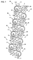
FIG. 1 is a schematic sectional side elevation view of a substantial portion of a double-sided image forming apparatus according to a first embodiment of the invention. -
FIG. 2 is a plan view of a first front-side recording unit inFIG. 1 . -
FIG. 3 is a schematic sectional side elevation view of a first front-side recording unit in accordance with a second embodiment of the invention. -
FIG. 4 is a schematic side view of the first front-side recording unit in accordance with the second embodiment. -
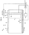
FIG. 5 is a schematic plan view of the first front-side recording unit in accordance with the second embodiment. -
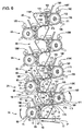
FIG. 6 is a schematic sectional side elevation view of a double-sided image forming apparatus according to a third embodiment of the invention. - A first embodiment of the invention will be described with reference to
FIGS. 1 and2 . -
FIG. 1 is a schematic sectional side elevation view of a substantial portion of a double-sided image forming apparatus including front-side recording units and rear-side recording units which are of an ink jet type and of a line recording type.FIG. 2 is a plan view of one front-side recording unit inFIG. 1 . InFIG. 1 , a recording sheet of paper (hereinafter, referred to as "recording sheet") is transported upwardly from below to the left, to the right, and so on.FIG. 2 illustrates a recording sheet which is being transported just after the start of printing. - Referring to
FIG. 1 , the double-sided image forming apparatus according to this embodiment includes a first front-side recording unit 1A, a first rear-side recording unit 1B, a second front-side recording unit 2A, a second rear-side recording unit 2B, a third front-side recording unit 3A, a third rear-side recording unit 3B, a fourth front-side recording unit 4A, and a fourth rear-side recording unit 4B in that order from upstream to downstream in the sheet transporting direction in which the recording sheet is transported. In this embodiment, the four front-side recording units side recording units - As shown in
FIGS. 1 and2 , a line printer (hereinafter, simply referred to as "printer") 11, serving as the first front-side recording unit 1A, includes abelt transport 12 for transporting a recording sheet P. Thebelt transport 12 has a driving drum (hereinafter, simply referred to as "drum") 13 disposed on the upstream side in the sheet transporting direction, a driven roller (hereinafter, referred to as "roller") 14 placed on the downstream side in the sheet transporting direction, and an endless belt (hereinafter, simply referred to as "belt") 15 stretched between thedrum 13 and theroller 14. Arotating shaft 13a of thedrum 13 and arotating shaft 14a of theroller 14 are rotatably supported by bearings (not shown), respectively. - The
drum 13 has an outer diameter and surface configuration similar to those of a related-art drum used for performing recording on a recording sheet P on the surface (smoothly curved) of the drum while the sheet is in contact with the surface of the drum and the drum surface is used as a platen. Certainly, thedrum 13 is not limited to this configuration. Since thedrum 13 is used while being wrapped with thebelt 15, thedrum 13 may have a configuration in which recording can be performed on the surface of thebelt 15 wrapping around thedrum 13 in a manner similar to that on the above-described smoothly curved surface of the drum. Therefore, it is not necessary that thedrum 13 have a smooth surface. - The
drum 13 is connected to an output shaft of anelectric motor 16 shown inFIG. 2 directly or through a speed reducing mechanism (not shown) such that theelectric motor 16 can transfer power to thedrum 13. When theelectric motor 16, serving as a driving source, is driven forward, thedrum 13 is rotated, so that thebelt 15 rotates in the direction in which the recording sheet P can be transported from the upstream side to the downstream side. A pair ofgate rollers 17, constituting a feeder, is arranged upstream of thebelt transport 12 in the sheet transporting direction and is located under thedrum 13. The recording sheet P is fed onto thebelt 15 so as to be transported on thebelt 15 wrapping around thedrum 13 by rotation of thegate rollers 17. - The
gate rollers 17 correct a skew of the recording sheet P when the leading edge of the recording sheet P is struck against the surfaces of thegate rollers 17. In addition, thegate rollers 17 adjust the time at which driving of the rollers is started in order to feed the recording sheet P so as to mount the sheet onto a target position in thebelt 15. Thebelt 15 has an endless form obtained by, for example, connecting both ends of the belt. The recording sheet P is fed so as not to be mounted on the joint of thebelt 15. - The
belt 15 is made of rubber. In this embodiment, the surface of the rubber belt has well-known adhesion properties such that the belt can hold the recording sheet P. Obviously, well-known electrostatic attraction or negative pressure suction, which will be described later, may be used to hold the recording sheet P on the surface of thebelt 15. - A line recording type recording head (hereinafter, referred to as "line head") 19K, serving as a recording member, is disposed above the
drum 13 so as to face the outer curved surface of thedrum 13. Theline head 19K discharges ink droplets of black (K). The ink to be discharged is supplied from an ink tank (not shown) of black (K) ink through an ink supply tube to theline head 19K. - The
line head 19K has a plurality of nozzles arranged in the direction intersecting (perpendicular to) the sheet transporting direction such that the length of arrangement of the nozzles allows for recording across a maximum width of the recording sheet P. Those nozzles simultaneously discharge a necessary amount of ink droplets to necessary portions in the recording sheet P, so that minute ink dots are formed in the recording sheet P. Consequently, recording in black for characters or an image to be recorded on the recording sheet P can be performed during only one pass in which the recording sheet P is allowed to once pass through a transport path between theline head 19K and thebelt 15. - So long as the
line head 19K includes a plurality of unit heads arranged in different positions in the direction (along the width of the recording sheet P) intersecting the sheet transporting direction such that printing across the whole width of the recording sheet P can be performed by the unit heads, at least some of the unit heads may be disposed in different positions in the sheet transporting direction. - Referring to
FIG. 2 , a magneticlinear encoder 20 is disposed on one side of thebelt 15. The magneticlinear encoder 20 includes a magneticlinear scale 21 and amagnetic sensor 22. The magneticlinear scale 21 is disposed on the whole of the periphery of the side of the belt. Themagnetic sensor 22 detects a magnetic pattern magnetized with a predetermined pitch on the magneticlinear scale 21 and reproduces the pattern. Themagnetic sensor 22 outputs an encoder signal including pulses whose number is proportional to the amount of rotation of thebelt 15. Theprinter 11 further includes acontroller 23 serving as a control section. Thecontroller 23 controls theelectric motor 16 in accordance with the encoder signal supplied from themagnetic sensor 22 so as to drive theelectric motor 16 at constant speed corresponding to a recording mode at that time. Thecontroller 23 also controls ejection timing of ink droplets on the basis of a recording reference pulse (ejection timing signal) generated on the basis of the encoder signal through an internal circuit so that the ink droplets are ejected to the transported sheet in a proper position. - In
FIGS. 1 and2 , the ratio of the diameters of thedrum 13 and theroller 14 is schematically shown. Thedrum 13 actually has a diameter that is three to ten times as large as that of theroller 14. For example, when the diameter of theroller 14 is 3 cm, it is preferred that the diameter of thedrum 13 range from 9 to 30 cm. The reason why the ratio of the diameters is set as described above is as follows: The large diameter of thedrum 13 ensures a large inertia in order to obtain stable rotation and also ensures provision of an area for arrangement of theline head 19K performing printing on the outer curved surface of the drum. - The mass of the
drum 13 also affects the inertia. It is therefore preferred to set the outer diameter of thedrum 13 in consideration of the mass so that the motion of thebelt 15 is significantly affected by thedrum 13 rather than by theroller 14. - When the recording sheet P, transported on the
belt 15, reaches theroller 14, the recording sheet P has to be removed from thebelt 15. In this embodiment, the curvature of part, wrapping around theroller 14, of thebelt 15 is determined so that the recording sheet P self-strips from thebelt 15 due to the stiffness of the recording sheet P. The curvature of thebelt 15 necessary for self-stripping of the recording sheet P is determined from the stiffness of the recording sheet P and the diameter of theroller 14 is then determined so as to obtain this curvature. Strippingpawls 24 for forcibly stripping the recording sheet P are disposed near a self-stripping position for the recording sheet P and downstream of the self-stripping position in the sheet transporting direction. The strippingpawls 24 are arranged in the direction along the width of thebelt 15. The strippingpawls 24 are come into contact with parts of the recording sheet P, which does not perform self-stripping, in the direction along the width of the sheet, thereby stripping the recording sheet P from thebelt 15. The strippingpawls 24 may be arranged in the self-stripping position. - The structure of a line printer (hereinafter, simply referred to as "printer") 111, serving as the first rear-
side recording unit 1B, will be described below. The first rear-side recording unit 1B also has abelt transport 112 having the same configuration as that of thebelt transport 12 in the first front-side recording unit 1A. Thebelt transport 112 has a driving drum (hereinafter, referred to as "drum") 113 disposed on the upstream side in the sheet transporting direction, a driven roller (hereinafter, referred to as "roller") 114 placed on the downstream side in the sheet transporting direction, and an endless belt (hereinafter, simply referred to as "belt") 115 stretched between thedrum 113 and theroller 114. Arotating shaft 113a of thedrum 113 and arotating shaft 114a of theroller 114 are rotatably supported by bearings (not shown), respectively. - The
printer 111 further has aline head 119K corresponding to theline head 19K and strippingpawls 124 corresponding to the strippingpawls 24. In addition, theprinter 111 includes an electric motor corresponding to theelectric motor 16, a magnetic linear encoder (including a magnetic linear scale and a magnetic sensor) corresponding to the magneticlinear encoder 20, and a controller corresponding to thecontroller 23. The electric motor, the magnetic linear encoder, and the controller in theprinter 111 are not shown inFIG. 1 . - Referring to
FIG. 1 , the recording sheet P transported while being held on the surface of thebelt 15 of the first front-side recording unit 1A is transferred to the first rear-side recording unit 1B such that part, passed under theline head 19K, of the recording sheet P is transported onto part of thebelt 115 of the first rear-side recording unit 1B, the part of thebelt 115 being upstream of theline head 119K and wrapping around thedrum 113 in the first rear-side recording unit 1B. - The second front-
side recording unit 2A has the same structure as that of the first front-side recording unit 1A, except that aline head 19C of cyan (C) is included instead of theline head 19K. Accordingly, the same components are designated by the same reference numerals and explanation of those components is omitted. The second rear-side recording unit 2B has the same structure as that of the first rear-side recording unit 1B, except that aline head 119C of cyan (C) is included instead of theline head 119K. Accordingly, the same components are designated by the same reference numerals and explanation of those components is omitted. - The third front-
side recording unit 3A has the same structure as that of the first front-side recording unit 1A, except that aline head 19M of magenta (M) is included instead of theline head 19K. Accordingly, the same components are designated by the same reference numerals and explanation of those components is omitted. The third rear-side recording unit 3B has the same structure as that of the first rear-side recording unit 1B, except that aline head 119M of magenta (M) is included instead of theline head 119K. Accordingly, the same components are designated by the same reference numerals and explanation of those components is omitted. - The fourth front-
side recording unit 4A has the same structure as that of the first front-side recording unit 1A, except that aline head 19Y of yellow (Y) is included instead of theline head 19K. Accordingly, the same components are designated by the same reference numerals and explanation of those components is omitted. The fourth rear-side recording unit 4B has the same structure as that of the first rear-side recording unit 1B, except that aline head 119Y of yellow (Y) is included instead of theline head 119K. Accordingly, the same components are designated by the same reference numerals and explanation of those components is omitted. In the following description, the line heads 19Y, 19M, 19C, and 19K and the line heads 119Y, 119M, 119C, and 119K will be referred to as line heads 19 and 119 unless the different ink colors are especially distinguished from one another. - In the double-sided image forming apparatus with the above-described structure (i.e., including the first front-
side recording unit 1A, the first rear-side recording unit 1B, the second front-side recording unit 2A, the second rear-side recording unit 2B, the third front-side recording unit 3A, the third rear-side recording unit 3B, the fourth front-side recording unit 4A, and the fourth rear-side recording unit 4B), when recording is started, a recording sheet P is fed from thegate rollers 17 onto thedrum 13 disposed on the upstream side in the sheet transporting direction in the first front-side recording unit 1A inFIG. 1 . The recording sheet P is mounted on thebelt 15 such that the sheet is in tight contact with (or adheres to) thebelt 15 due to the adhesion properties of the surface of thebelt 15. - The
belt 15 is driven by the force of the drivingdrum 13, so that thebelt 15 rotates so as to follow the motion of thedrum 13. Since the motion of thebelt 15 depends on thedrum 13, the motion of the recording sheet P mounted on thebelt 15 also depends on thedrum 13. Thedrum 13, which has the large inertia, stably rotates during rotating at constant speed. Even when a fluctuation in speed occurs in the driven roller, the rotation of thebelt 15 on thedrum 13 is stable. Accordingly, this fluctuation hardly causes vibration of thebelt 15. Consequently, transport by the belt is remarkably stable, thus achieving high-speed and high-image-quality printing. - The orientation of the
belt 15 depends on thedrum 13 because the amount of wrap of thebelt 15 around thedrum 13 is larger than that around theroller 14. If a fluctuation in speed occurs in the driven roller having a smaller diameter, thebelt 15 is stably rotated, so that thebelt 15 hardly meanders. - Even when the
belt 15 skews relative to thedrum 13, the recording sheet P is moved so as to follow thedrum 13 irrespective of thebelt 15 interposing between the recording sheet P and thedrum 13. In other words, even when thebelt 15 skews relative to thedrum 13 and the recording sheet P skews relative to the skewingbelt 15, the recording sheet P is mounted on thebelt 15 so as not to skew relative to thedrum 13. Consequently, if thebelt 15 on which the recording sheet P is mounted skews, the recording sheet P is stably transported so as to follow thedrum 13 so long as the recording sheet P is fed onto thebelt 15 on thedrum 13 while being held in a correct orientation and position. - Since the
line printer 11, serving as the first front-side recording unit 1A, is configured to perform recording using the line recordingtype line head 19K, theprinter 11 carries out recording onto the front side of a recording sheet P while rotating thedrum 13 at constant rotational speed. If theprinter 11 uses a serial recording method, each time a serial recording head moves in the thrust direction of the drum for scanning, the drum having the large inertia alternates between driving and stopping. This results in a reduction in stop position accuracy of the drum. In contrast, in the use of the line head, since recording can be performed while thedrum 13 is being rotated at constant speed, stable rotation of thedrum 13 increases the transport position accuracy of a recording sheet P, so that high image quality recording can be performed on the recording sheet P. In this instance, recording is performed at high speed. Printing of one sheet of paper by the first front-side recording unit 1A is finished for a period of time (for example, 0.1 to 5 seconds) during which thedrum 13 rotates once or twice. - The recording sheet P whose "front side" has been subjected to recording in black by the
line head 19K is transported to a position corresponding to theroller 14 disposed on the downstream side of the sheet transporting direction inFIG. 1 while being mounted on thebelt 15. The recording sheet P self-strips from the curved surface of thebelt 15 in which the curvature significantly varies depending on the diameter of theroller 14 and is then transferred to the first rear-side recording unit 1B. The recording sheet P stuck on thebelt 15 is bent so that the recording sheet P peels off (self-strips from) thebelt 15 only due to the stiffness of the sheet. Thus, the recording sheet P is removed from thebelt 15. If part of the recording sheet P does not self-strip, the part is peeled off by the strippingpawls 24. - As shown in
FIG. 1 , the recording sheet P, which has been transferred to the first rear-side recording unit 1B, is transported on part, wrapping around thedrum 113, of thebelt 115, the part being upstream of theline head 119K in the first rear-side recording unit 1B. The "rear side" of the recording sheet P is subjected to recording in black by theline head 119K and is then transported on thebelt 115 to a position corresponding to theroller 114 on the downstream side in the sheet transporting direction inFIG. 1 . In this position, the recording sheet P self-strips from the curved surface of thebelt 115 in which the curvature of thebelt 115 significantly varies depending on the diameter of theroller 114, alternatively, the recording sheet P is peeled off by the strippingpawls 124. After that, the recording sheet P is then transferred to the second front-side recording unit 2A. - In the second front-
side recording unit 2A, the "front side" of the recording sheet P is subjected to recording in cyan through theline head 19C and the recording sheet P is then transferred to the second rear-side recording unit 2B. In the second rear-side recording unit 2B, the "rear side" of the recording sheet P is subjected to recording in cyan through theline head 119C and the recording sheet P is then transferred to the third front-side recording unit 3A. - In the third front-
side recording unit 3A, the "front side" of the recording sheet P is subjected to recording in magenta through theline head 19M and the recording sheet P is then transferred to the third rear-side recording unit 3B. In the third rear-side recording unit 3B, the "rear side" of the recording sheet P is subjected to recording in magenta through theline head 119M and the recording sheet P is then transferred to the fourth front-side recording unit 4A. - In the fourth front-
side recording unit 4A, the "front side" of the recording sheet P is subjected to recording in yellow through theline head 19Y and the recording sheet P is then transferred to the fourth rear-side recording unit 4B. In the fourth rear-side recording unit 4B, the "rear side" of the recording sheet P is subjected to recording in yellow through theline head 119Y. Consequently, recording on a color-by-color basis, i.e., recording in all of four ink colors on the recording sheet P is finished. The resultant recording sheet P self-strips from the curved surface of thebelt 115, alternatively, the recording sheet P is peeled from thebelt 115 by the strippingpawls 124 and is then ejected to the outside of the double-sided image forming apparatus. - As described in detail above, the first embodiment has the following advantages.
- The "front side" and the "rear side" of a recording sheet are alternately subjected to recording in the four ink colors (black, cyan, magenta, and yellow) on the color-by-color basis through the first front-
side recording unit 1A, the first rear-side recording unit 1B, the second front-side recording unit 2A, the second rear-side recording unit 2B, the third front-side recording unit 3A, the third rear-side recording unit 3B, the fourth front-side recording unit 4A, and the fourth rear-side recording unit 4B in the order of the front side, the rear side, the front side, and the rear side such that the first front-side recording unit 1A performs recording in black on the front side of the recording sheet, the first rear-side recording unit 1B performs recording in black on the rear side thereof, the second front-side recording unit 2A performs recording in cyan on the front side thereof, the second rear-side recording unit 2B performs recording in cyan on the rear side thereof, and so fourth. - Consequently, ink adhesion on both of the "front side" and the "rear side" of the recording sheet P can progress evenly, thus eliminating a cause of curling of the recording sheet and reducing the difference in recording quality between the "front side" and the "rear side" thereof.
- Since the "front side" and the following "rear side" of the recording sheet P are subjected to recording in the same color, the front and rear sides, applied with the same color ink, e.g., black ink, of the recording sheet have the same degree of change in state, such as distortion or swelling, caused by the ink adhesion to the recording sheet, so that the changed states of the front and rear sides are easily cancelled out. Accordingly, when the "front side" of the recording sheet P is then subjected to recording with the cyan ink, the recording sheet P can be set in a condition close to the "both sides identical condition". Advantageously, the difference in recording quality between the front and rear sides of the recording sheet P can be further reduced.
- The fed recording sheet P is subjected to recording through the line heads 19 and 119 such that part, located above the stably rotating drum (13, 113) having the large diameter and large inertia, of the recording sheet is subjected to recording. Accordingly, recording can be performed at high recording position accuracy. In addition, since the line heads 19 and 119 are used as recording members, recording can be carried out while the
drums drums - Since the
belts belts - The
rollers drums belts JP-A-2003-94615 - The diameter of each of the
drums rollers drums rollers line printers drums - As for each
belt 15 stretched between thedrum 13 and theroller 14 and eachbelt 115 stretched between thedrum 113 and theroller 114, even when the suspended part of the belt vibrates or the belt oscillates due to a fluctuation in speed of the corresponding roller having a small inertia every speed fluctuation cycle, such vibration or oscillation does not propagate through part, held on the belt wrapping around the drum, of the recording sheet P. Advantageously, this results in an increase in recording quality in double-sided recording. - A double-sided image forming apparatus according to a second embodiment of the invention will be described with reference to
FIGS. 3 to 5 . -
FIG. 3 is a schematic sectional side elevation view of a first front-side recording unit included in the double-sided image forming apparatus according to the second embodiment.FIG. 4 is a schematic side view of the first front-side recording unit.FIG. 5 is a plan view of the first front-side recording unit. In the double-sided image forming apparatus according to the second embodiment, a first rear-side recording unit, a second front-side recording unit, a second rear-side recording unit, a third front-side recording unit, a third rear-side recording unit, a fourth front-side recording unit, and a fourth rear-side recording unit basically have the same structure as that of the first front-side recording unit. Accordingly, those components are not shown inFIGS. 3 to 5 and explanation of the components is omitted. - A feature of the double-sided image forming apparatus according to the second embodiment is that negative pressure suction is used in belts, this feature being different from that of the first embodiment.
- Referring to
FIG. 3 , a line printer (hereinafter, simply referred to as "printer") 31, serving as the first front-side recording unit 1A, includes adrum 13. Thedrum 13 hasmany suction holes 13b such that the suction holes 13b are scattered over the whole outer curved surface of thedrum 13. Abelt 15 also hasmany suction holes 15a such that thesuction holes 15a are scattered over the whole of thebelt 15. Thedrum 13 and thebelt 15 are configured so that at least some of the suction holes 13b of thedrum 13 always communicate with at least some of the suction holes 15a of thebelt 15 even when part, wrapping around thedrum 13, of thebelt 15 slightly shifts relative to thedrum 13. For this purpose, for example, the suction holes 13b may be arranged at random in thedrum 13 and thesuction holes 15a may be arranged at random in thebelt 15. Alternatively, the diameter of each suction hole in one of thedrum 13 and thebelt 15 may be larger than the diameter of each suction hole in the other one. - As shown in
FIG. 4 and5 , both side faces (extending perpendicular to the drawing sheet ofFIG. 5 ) of theprinter 31 are closed byside plates 32 so that the air is not leaked out from thedrum 13 excluding portions for emitting the air. A clearance between eachside plate 32 and each of movable members, i.e., thedrum 13, aroller 14, and thebelt 15 is sealed with, for example, a contact seal or a well-known sealing member having a labyrinth structure. - Referring to
FIG. 5 , the side plate 32 (upper side plate inFIG. 5 ) is connected to one end of apipe 33 that communicates with the internal space of thedrum 13. The other end of thepipe 33 is connected to afan 34. Thecontroller 23 drives thefan 34, so that the air in adrum chamber 35, serving as the internal space of thedrum 13, is sucked and discharged to the outside of thedrum 13. Thus, the inside of thedrum 13 is held at negative pressure. Abelt chamber 36, serving as a substantially closed space, is enclosed by the twoside plates 32, thedrum 13, and theroller 14. Thebelt chamber 36 communicates with the inside of thedrum 13 through the suction holes 13b. Therefore, when the inside of thedrum 13 is held at negative pressure, the inside of thebelt chamber 36 is also held at negative pressure. - The negative pressure in the
belt chamber 36 causes suction air current flowing from the outer curved surface of thebelt 15 through the suction holes 15a of thebelt 15 to thebelt chamber 36. A recording sheet P subjected to recording is transported on thebelt 15 while being attracted to the upper surface of thebelt 15 by suction. For example, when air current (wind) having a predetermined force is applied to a recorded portion, which has been subjected to recording, of the recording sheet on the upper portion of thebelt 15, the recorded portion does not curl upward away from the upper surface of thebelt 15 and the recording sheet is stably transported. Accordingly, a portion that is being or to be subjected to recording in the recording sheet P can be prevented from shifting relative to thedrum 13 due to the curling of the recorded portion in the recording sheet P. - The recording sheet P is attracted onto the
belt 15 by suction. Since the recording sheet P can be mounted onto the downwardly facing surface, located on the lower side in the direction of gravity, of thebelt 15,gate rollers 17 are arranged under thedrum 13 such that the distance between thedrum 13 and therollers 17 is longer than that in the first embodiment. Accordingly, the position at which the recording sheet P is fed to thedrum 13 is shifted lower than that in the first embodiment relative to the outer curved surface of thedrum 13, so that the amount of wrap of the recording sheet P around thedrum 13 can be increased. - In the
printer 31, thefan 34 is driven to discharge the air from the inside of thedrum 13, thus causing air current flowing into the inside of thedrum 13 through the suction holes 13b of thedrum 13 and the suction holes 15a of thebelt 15. Consequently, the recording sheet P is transported on thebelt 15 while being attracted to thebelt 15 by suction. Since the recording sheet P is prevented from shifting relative to thedrum 13, the recording sheet P can be stably transported with high reliability. - When the recording sheet P is transported up to a position corresponding to the
roller 14 located on the downstream side in the sheet transporting direction (left inFIG. 3 ), the suction holes 15a of part, wrapping around theroller 14, of thebelt 15 are closed by the outer curved surface of theroller 14, so that suction force is not allowed to act on the recording sheet P on thebelt 15. Consequently, the recording sheet P can be easily peeled from thebelt 15 by elimination of the suction force due to closing the suction holes 15a and self-stripping of the recording sheet P due to theroller 14. Since stripping pawls (separation pawls) 24 are arranged in the same way as the first embodiment, even if a portion of the recording sheet P does not self-strip from thebelt 15, the portion can be reliably peeled off by the strippingpawls 24. - The second embodiment has the following advantages.
- The inside of the
drum 13 is brought under negative pressure by driving thefan 34, so that the recording sheet P is attracted to part, wrapping around thedrum 13, of thebelt 15 by suction through the suction holes 13b of thedrum 13 and the suction holes 15a of thebelt 15. Consequently, the recording sheet P can be more reliably prevented from shifting relative to thedrum 13. Advantageously, the high recording position accuracy for the recording sheet P can be maintained. - The
belt chamber 36 communicating with the inside (i.e., the drum chamber 35) of thedrum 13 through thesuction holes 13b is also brought under negative pressure. Accordingly, the recording sheet P, which has been subjected to recording, can be transported while being attracted to thebelt 15 by suction. Furthermore, since the suction holes 15a of thebelt 15 are closed by the outer curved surface of theroller 14 in a zone where the recording sheet P self-strips, suction force does not act on the recording sheet P on thebelt 15, so that the recording sheet P can easily self-strip. - Since the recording sheet P is attracted to the
belt 15 by suction, the recording sheet P can be mounted on the downwardly facing surface of thebelt 15 against gravity. Accordingly, the amount of wrap of thebelt 15 around the outer curved surface of thedrum 13 and the amount of wrap (or the length of wrap) of the recording sheet P around thebelt 15 can be ensured to be large (or long) in the direction along the circumference of thedrum 13. Thus, an arrangement area for the line head 19 which should be arranged so as to face a portion, around which a recording sheet P wraps, of the outer curved surface of thedrum 13 can be provided such that the length of the arrangement area in the direction along the circumference of thedrum 13 is long. Advantageously, when it is necessary to arrange many line heads 19 because the number of ink colors is increased to five or more, such an arrangement area can be ready for the many line heads 19. In a case where the number of line heads is not increased, the flexibility in selection of the arrangement position of the line head 19 can be increased. - A double-sided image forming apparatus according to a third embodiment of the invention will be described with reference to
FIG. 6. FIG. 6 is a schematic sectional side elevation view of the double-sided image forming apparatus according to the third embodiment. - Referring to
FIG. 6 , like as the double-sided image forming apparatuses according to the foregoing embodiments, the double-sided image forming apparatus according to this embodiment includes a first front-side recording unit 1A, a first rear-side recording unit 1B, a second front-side recording unit 2A, a second rear-side recording unit 2B, a third front-side recording unit 3A, a third rear-side recording unit 3B, a fourth front-side recording unit 4A, and a fourth rear-side recording unit 4B in the sheet transporting direction in which a recording sheet P is transported, those units being of the line recording type. - In this embodiment, the four front-
side recording units drum 13 and two rollers. Similarly, the four rear-side recording units drum 113 and two rollers. Specifically, the four front-side recording units first roller 141 and asecond roller 142 and the four rear-side recording units first roller 1141 and asecond roller 1142. In other words, each recording unit has a three-axis structure. - The first front-
side recording unit 1A and the first rear-side recording unit 1B will be described below. Since the second front-side recording unit 2A, the third front-side recording unit 3A, and the fourth front-side recording unit 4A have the same structure as that of the first front-side recording unit 1A and the second rear-side recording unit 2B, the third rear-side recording unit 3B, and the fourth rear-side recording unit 4B have the same structure as that of the first rear-side recording unit 1B, the same components as those of the first front-side recording unit 1A and the first rear-side recording unit 1B are designated by the same reference numerals and explanation of thoseunits - A
transfer section 4 where a recording sheet P is to be transferred between the units is provided by surface contact between abelt 15 of the first front-side recording unit 1A and abelt 115 of the first rear-side recording unit 1B, the surface contact having a predetermined area extending in the sheet transporting direction. - The
transfer section 4 is located between thefirst roller 141, serving as a section 6 that separates a recording sheet P, in the first front-side recording unit 1A and thesecond roller 1142, serving as asection 8 that receives the recording sheet P, in the first rear-side recording unit 1B. An angle θ1 formed by thebelt 15 wrapping around thefirst roller 141, serving as the separating section 6, is an acute angle. An angle θ2 formed by thebelt 115 wrapping around thesecond roller 1142, serving as the receivingsection 8, is an obtuse angle. - In this embodiment, a halogen lamp, serving as a drying
section 61, is disposed between aline head 19K of the first front-side recording unit 1A and thesecond roller 1142, serving as the receivingmember 8, in the first rear-side recording unit 1B. In addition, aprotective barrier 90 that protects heat transfer is disposed near the dryingsection 61 so as to be located upstream from the dryingsection 61. Instead of the halogen lamp, the dryingsection 61 may include a light dryer, such as a xenon lamp, a mercury lamp that emits ultraviolet light curing UV curable ink, or an LED lamp. Alternatively, heat of radiation, a current of normal temperature air, or a current of warm air approximately ranging from 60 to 250 °C may be used. - The first front-
side recording unit 1A further includes a firstnegative pressure section 71 that attracts a recording sheet P to at least part, wrapping around thedrum 13, of thebelt 15 by negative pressure suction. The firstnegative pressure section 71 includes suction holes 13b and 15a, apipe 33, afan 34, and twoside plates 32 similar to those in the second embodiment (FIG. 3 ), those components of thesection 71 being not shown inFIG. 6 . - The first front-
side recording unit 1A further includes a secondnegative pressure section 72 and a thirdnegative pressure section 73 in aspace 47 that is provided on the inside of thebelt 15 and on the outside of thedrum 13. The secondnegative pressure section 72 attracts a recording sheet P to the outer surface of part, located upstream of the part wrapping around thedrum 13, of thebelt 15 by negative pressure suction. The thirdnegative pressure section 73 attracts the recording sheet P to the outer surface of part, located downstream of the part wrapping around thedrum 13, of thebelt 15 by negative pressure suction. - The third
negative pressure section 73 is separated from the firstnegative pressure section 71 and the secondnegative pressure section 72 by apartition 63. In this embodiment, thepartition 63 is disposed so that the firstnegative pressure section 71 and the secondnegative pressure section 72 are brought under negative pressure by negative pressure generated due to discharge of a gas into thedrum 13 through the suction holes (13b) of thedrum 13 and suction force is generated through the suction holes (15a) in the part, upstream of the other part wrapping around thedrum 13, of thebelt 15. Thespace 47 enclosed by thepartition 63 and thebelt 15 is substantially hermetically sealed. - A
sensor 65 for detecting the position of a recording sheet P is disposed upstream of theline head 19K. Thesensor 65 detects the leading edge of the recording sheet P and the first front-side recording unit 1A can perform recording on the recording sheet P. Advantageously, recording on the "front side" of the sheet can be performed with high recording position accuracy. - In this embodiment, a
belt speed sensor 80 is disposed near theline head 19K so as to be located upstream of theline head 19K. Thebelt speed sensor 80 determines actual speed of thebelt 15 so that ink discharge timing can be controlled at high accuracy. - The structure of the first rear-
side recording unit 1B is the same as that of the first front-side recording unit 1A. The first front-side recording unit 1A carries out recording on the "front side" of a recording sheet P. In contrast, the first rear-side recording unit 1B carries out recording on the "rear side" thereof. Accordingly, the same components, constituting the first rear-side recording unit 1B, as those of theunit 1A are designated by the same reference numerals and explanation of the components of theunit 1B is omitted. - The third embodiment has the following advantages.
- According to this embodiment, each
transfer section 4 for a recording sheet P is provided by surface contact between thebelts side recording unit 1A and the first rear-side recording unit 1B (or the first rear-side recording unit 1B and the second front-side recording unit 2A, or the second front-side recording unit 2A and the second rear-side recording unit 2B, ...), the surface contact having a predetermined area extending in the sheet transporting direction. Accordingly, in eachtransfer section 4, the front and rear sides of a recording sheet P are supported by thebelts belt 115 of the first rear-side recording unit 1B disposed downstream of thetransfer section 4. Consequently, the recording sheet P is smoothly transferred from, for example, thebelt 15 of the first front-side recording unit 1A to thebelt 115 of the first rear-side recording unit 1B, thus preventing a reduction in recording quality caused by sheet transfer between the adjacent recording units. - In addition, the first front-
side recording unit 1A, the first rear-side recording unit 1B, the second front-side recording unit 2A, the second rear-side recording unit 2B, the third front-side recording unit 3A, the third rear-side recording unit 3B, the fourth front-side recording unit 4A, and the fourth rear-side recording unit 4B each include the one drum (13 or 113) and the two rollers (141 and 142 or 1141 and 1142), i.e., each have the three-axis structure. Advantageously, the flexibility in design of the entire structure can be increased. Consequently, a space for arrangement of other components, e.g., dryingsections sensors - The
transfer section 4 is located between, for example, thefirst roller 141, serving as the section 6 for separating a recording sheet P, in the first front-side recording unit 1A and thesecond roller 1142, serving as thesection 8 for receiving the recording sheet P, in the first rear-side recording unit 1B. The angle θ1 formed by thebelt 15 wrapping around thefirst roller 141, serving as the separating section 6, is the acute angle. The angle θ2 formed by thebelt 115 wrapping around thesecond roller 1142, serving as the receivingsection 8, is the obtuse angle. Consequently, in a case where a recording sheet P, whose "front side" has been subjected to recording in the first front-side recording unit 1A, enters thetransfer section 4 toward the first rear-side recording unit 1B, if the leading edge of the recording sheet P floats, the above-described obtuse-angle arrangement can easily eliminate the floating of the recording sheet P so that the recording sheet P enters thetransfer section 4. After that, the recording sheet P can be easily separated from thebelt 15 of the first front-side recording unit 1A in the exit of thetransfer section 4 by the above-described acute-angle arrangement and be smoothly transported such that the sheet is held only by thebelt 115 of the first rear-side recording unit 1B. - In this embodiment, one recorded side of each recording sheet P is dried by the drying section (61, 161) and, after that, the other side thereof is subjected to recording. Accordingly, a reduction in recording quality can be prevented.
- Each recording sheet P is attracted to at least part, wrapping around the drum (13, 113), of the belt (15, 115) by suction under negative pressure generated by the first negative pressure section (71, 171). Consequently, the recording sheet P can be effectively prevented from shifting relative to the outer curved surface of the drum (13, 113) driven stably. Advantageously, shifting of the recording sheet P relative to the drum (or belt) can be effectively prevented, thus easily obtaining high recording position accuracy.
- For example, the first front-
side recording unit 1A and the first rear-side recording unit 1B each have the second negative pressure section (72, 172) and the third negative pressure section (73, 173) for attracting a recording sheet P to the outer surface of the belt (15, 115). Accordingly, the recording sheet P can be transported while being held on the belt (15, 115) and be smoothly transferred between the recording units. - Each third negative pressure section (73, 173) is separated from the corresponding first negative pressure section (71, 171) and the corresponding second negative pressure section (72, 172) through the partition (63, 163). In particular, therefore, in the arrangement of the components including the drying section (61, 161), heat applied to the belt (15, 115) for drying can be eliminated by suction exhaust stream, serving as a negative pressure generating source of the third negative pressure section (73, 173), so that the heat is not propagated toward the drum (13, 113). Consequently, unnecessary heat can be prevented from propagating to the drum (13, 113). Thus, any trouble, such as nozzle clogging, caused by propagation of unnecessary heat through a recording head located near the drum (13, 113) can be prevented.
- The above-described embodiments have been described with respect to the double-sided image forming apparatus for performing recording with inks of four different colors. However, the number of ink colors is not limited to four. The number of ink colors may be adequately set. For example, three colors, six colors, or eight colors may be used. The number of combination of the front-side recording unit and the rear-side recording unit may be increased or decreased depending on the number of ink colors, so that the double-sided image forming apparatus can be easily ready for multicolor recording. As a matter of course, the order of colors is not limited to that (black → cyan → magenta → yellow) in the foregoing embodiments.
- The invention may be applied to a recording apparatus for ejecting a pretreatment liquid or an overcoat liquid instead of ink.
- The above-described embodiments have been described with respect to the double-sided image forming apparatus in which a recording medium is transported by the belts while being transferred between the recording units. A transporting member is not limited to a belt. A transporting member using a roller or a guide may be used.
- The invention is not limited to an ink jet printer. The invention may be applied to a thermal transfer printer and may also be applied to a copy machine.
- A fluid-ejecting image forming apparatus is not limited to an ink jet printer. The apparatus may be embodied as a fluid ejecting apparatus that ejects or discharges a fluid other than ink, the fluid including a liquid, a liquid state material containing particles of a functional material dispersed therein or mixed therewith, a fluid state material, such as gel, or a solid material, such as a powder and granular material including toner, capable of flowing as a fluid and being ejected.
- The invention may be applied to, for example, a liquid state material ejecting apparatus that ejects a liquid state material containing a dispersed or dissolved material, such as an electrode material or a coloring material (pixel material) used in manufacture of a liquid crystal display, an electroluminescent (EL) display, or a surface emission display, a liquid ejecting apparatus that ejects liquid of transparent resin, such as UV curable resin, onto a substrate to form a micro hemispherical lens (optical lens) used in an optical communication element, a liquid ejecting apparatus that ejects an acidic or alkaline etching solution to etch a substrate, and a fluid state material ejecting apparatus that ejects a fluid state material, such as gel (e.g., physical gel).
- Predetermined patterns (including a wiring pattern, an electrode pattern, a pixel pattern, an etching pattern, and an arrangement pattern), each of which is formed by landing an ejected fluid on a recording medium, such as a substrate, in the above-described apparatuses are included in images formed by recording in this specification. The term "fluid" conceptually excludes a fluid composed of only gas and includes, for example, a liquid (e.g., an inorganic solvent, an organic solvent, a solution, a liquid resin, or a liquid metal (metal melt)), a powder and granular material, or a fluid state material.
Claims (10)
- A double-sided image forming apparatus comprising:front-side image forming units and rear-side image forming units arranged in the transporting direction in which a recording medium is transported, whereineach of the front-side image forming units and the rear-side image forming units includes:an endless belt that transports the recording medium; anda recording section that performs recording on the recording medium transported on the belt,the recording medium held and transported on the belt of one of the adjacent front-side image forming unit and rear-side image forming unit is transferred to the other image forming unit such that part, passed under the recording section of the one image forming unit, of the recording medium is transported onto part of the belt of the other image forming unit, the part of the belt being upstream of the recording section of the other image forming unit,the recording section of each of the front-side image forming units and the rear-side image forming units is configured to perform recording in a single color, andthe front-side image forming units and the rear-side image forming units are arranged so that the front side and the rear side of the recording medium are alternately subjected to recording on a color-by-color basis in the order of the front side, the rear side, the front side, and the rear side.
- The apparatus according to Claim 1, wherein each front-side image forming unit and the following rear-side image forming unit are configured to perform recording on the front and rear sides of the recording medium in the same color.
- The apparatus according to Claim 1 or 2, wherein
each of the front-side image forming units and the rear-side image forming units includes:a drum;a roller having a smaller diameter than the drum;the endless belt stretched between the drum and the roller;a driving source that rotates the drum to rotate the belt; andthe recording section of a line recording type, the recording section facing the outer curved surface of the drum so as to perform recording on the recording medium held on part, wrapping around the drum, of the belt, andthe recording medium held and transported on the belt of one of the adjacent front-side image forming unit and rear-side image forming unit is transferred to the other image forming unit such that part, passed under the recording section of the one image forming unit, of the recording medium is transported onto part of the belt of the other image forming unit, the part of the belt being upstream of the recording section of the other image forming unit and wrapping around the drum of the other image forming unit. - The apparatus according to Claim 3, wherein a transfer section where the recording medium is transferred between the adjacent image forming units is provided by surface contact between the belts of the adjacent front-side image forming unit and rear-side image forming unit, the surface contact having a predetermined area extending in the transporting direction.
- The apparatus according to Claim 4, wherein
all of the rear-side image forming units disposed downstream of at least the most upstream front-side image forming unit and the other front-side image forming units are each configured such that the number of drums is one and the number of rollers is two,
the transfer section is disposed between the roller, serving as a separating section that separates the recording medium, in one of the adjacent image forming units and the roller, serving as a receiving section that receives the recording medium, in the other image forming unit, and
an angle formed by the belt wrapping around the roller, serving as the separating section, is an acute angle and an angle formed by the belt wrapping around the roller, serving as the receiving section, is an obtuse angle. - The apparatus according to Claim 5, further comprising:a drying section disposed between the recording section of one of the adjacent image forming units and the roller, serving as the receiving section, of the other image forming unit.
- The apparatus according to Claim 3, further comprising:a first negative pressure section that attracts the recording medium to at least part, wrapping around the drum, of the belt by negative pressure suction, whereineach of the front-side image forming units and the rear-side image forming units includes a second negative pressure section and a third negative pressure section in a space provided on the inside of the belt and on the outside of the drum, the second negative pressure section attracting the recording medium to the outer surface of part, located upstream of the part wrapping around the drum, of the belt by negative pressure suction, the third negative pressure section attracting the recording medium to the outer surface of part, located downstream of the part wrapping around the drum, of the belt by negative pressure suction,the third negative pressure section is separated from the first and second negative pressure sections through a partition, anda space enclosed by at least the partition and the belt is substantially hermetically sealed.
- The apparatus according to any one of the preceding claims, wherein each image forming unit further includes a sensor that detects the position of the recording medium such that the sensor is disposed upstream of the recording section.
- A double-sided image forming apparatus for discharging different kinds of liquids to each of the front and rear sides of a recording medium to form images, the apparatus comprising:a first discharging unit that discharges one of the liquids to the front side of the recording medium;a second discharging unit that discharges one of the liquids to the rear side of the recording medium processed through the first discharging unit;a third discharging unit that discharges one of the liquids to the front side of the recording medium processed through the second discharging unit, the one liquid being not discharged by the first discharging unit; anda fourth discharging unit that discharges one of the liquids to the rear side of the recording medium processed through the third discharging unit, the one liquid being not discharged by the second discharging unit.
- A double-sided image forming method for discharging different kinds of liquids to the front and rear sides of a recording medium to form images, the method comprising the steps of:(a) discharging one of the liquids to the front side of the recording medium;(b) discharging one of the liquids to the rear side of the recording medium processed in step (a);(c) discharging one of the liquids to the front side of the recording medium processed in step (b), the one liquid being not discharged in step (a); and(d) discharging one of the liquids to the rear side of the recording medium processed in step (c), the one liquid being not discharged in step (b).
Applications Claiming Priority (1)
| Application Number | Priority Date | Filing Date | Title |
|---|---|---|---|
| JP2008007664A JP2009166375A (en) | 2008-01-17 | 2008-01-17 | Double-sided image forming apparatus and double-sided image forming method |
Publications (2)
| Publication Number | Publication Date |
|---|---|
| EP2080625A1 true EP2080625A1 (en) | 2009-07-22 |
| EP2080625B1 EP2080625B1 (en) | 2011-05-25 |
Family
ID=40377280
Family Applications (1)
| Application Number | Title | Priority Date | Filing Date |
|---|---|---|---|
| EP09000429A Ceased EP2080625B1 (en) | 2008-01-17 | 2009-01-14 | Double-sided image forming apparatus and method |
Country Status (3)
| Country | Link |
|---|---|
| US (1) | US20090185844A1 (en) |
| EP (1) | EP2080625B1 (en) |
| JP (1) | JP2009166375A (en) |
Families Citing this family (5)
| Publication number | Priority date | Publication date | Assignee | Title |
|---|---|---|---|---|
| JP2011121680A (en) * | 2009-12-09 | 2011-06-23 | Seiko Epson Corp | Conveyed medium conveying device and image forming device |
| US9145006B1 (en) | 2014-11-14 | 2015-09-29 | Eastman Kodak Company | Duplex printer for sheet and web printing |
| US9096084B1 (en) | 2014-11-14 | 2015-08-04 | Eastman Kodak Company | Printer for sheet and web printing |
| US9145007B1 (en) | 2014-11-14 | 2015-09-29 | Eastman Kodak Company | Duplex printer with print belts for sheet and web printing |
| JP7552236B2 (en) | 2020-10-13 | 2024-09-18 | 株式会社リコー | Sheet material conveying device, sheet material heating device, drying device, liquid ejection device, printing device |
Citations (3)
| Publication number | Priority date | Publication date | Assignee | Title |
|---|---|---|---|---|
| JP2003063707A (en) * | 2001-08-24 | 2003-03-05 | Hitachi Koki Co Ltd | Recording device |
| JP2003094615A (en) | 2001-09-20 | 2003-04-03 | Olympus Optical Co Ltd | Ink jet printer |
| JP2004195956A (en) | 2002-10-22 | 2004-07-15 | Ricoh Co Ltd | Ink jet recording device, copier and recording medium |
Family Cites Families (5)
| Publication number | Priority date | Publication date | Assignee | Title |
|---|---|---|---|---|
| JPH08174941A (en) * | 1994-12-27 | 1996-07-09 | Mita Ind Co Ltd | Image recording device |
| JPH08319051A (en) * | 1995-03-17 | 1996-12-03 | Toray Ind Inc | Printing apparatus and printing method |
| US6477950B1 (en) * | 2000-04-12 | 2002-11-12 | Michael Alan Feilen | Apparatus and method for duplex printing of a sheet-like substrate |
| JP2002001938A (en) * | 2000-06-20 | 2002-01-08 | Noritsu Koki Co Ltd | Image forming device |
| JP2003182031A (en) * | 2001-12-14 | 2003-07-03 | Komori Corp | Coating equipment |
-
2008
- 2008-01-17 JP JP2008007664A patent/JP2009166375A/en not_active Withdrawn
-
2009
- 2009-01-09 US US12/351,434 patent/US20090185844A1/en not_active Abandoned
- 2009-01-14 EP EP09000429A patent/EP2080625B1/en not_active Ceased
Patent Citations (3)
| Publication number | Priority date | Publication date | Assignee | Title |
|---|---|---|---|---|
| JP2003063707A (en) * | 2001-08-24 | 2003-03-05 | Hitachi Koki Co Ltd | Recording device |
| JP2003094615A (en) | 2001-09-20 | 2003-04-03 | Olympus Optical Co Ltd | Ink jet printer |
| JP2004195956A (en) | 2002-10-22 | 2004-07-15 | Ricoh Co Ltd | Ink jet recording device, copier and recording medium |
Also Published As
| Publication number | Publication date |
|---|---|
| US20090185844A1 (en) | 2009-07-23 |
| JP2009166375A (en) | 2009-07-30 |
| EP2080625B1 (en) | 2011-05-25 |
Similar Documents
| Publication | Publication Date | Title |
|---|---|---|
| US7722180B2 (en) | Liquid droplet discharge apparatus including duplex recording medium transport unit | |
| EP2067628B1 (en) | Double-sided recording apparatus | |
| JP5304430B2 (en) | Printing device | |
| EP2080625B1 (en) | Double-sided image forming apparatus and method | |
| JP2009279808A (en) | Correction information forming device, image forming apparatus and program | |
| US20090189967A1 (en) | Inkjet recording apparatus | |
| US20110134200A1 (en) | Apparatus for transporting transportation target medium and image formation apparatus | |
| JP5573450B2 (en) | Recording device | |
| US20210402809A1 (en) | Inkjet recording device | |
| US7954815B2 (en) | Segmented rigid plate belt transport with a high motion quality drive mechanism | |
| JP2005170547A5 (en) | ||
| US12091280B2 (en) | Conveyance apparatus | |
| JP2008073958A (en) | Image recorder | |
| JP4487526B2 (en) | Recording device | |
| JP2008222418A (en) | Inkjet recording device | |
| JP5353593B2 (en) | Image forming apparatus and double-sided image forming apparatus | |
| JP4720925B2 (en) | Inkjet recording device | |
| WO2019116788A1 (en) | Image forming device | |
| JP6252460B2 (en) | Inkjet recording device | |
| JP6027501B2 (en) | Inkjet recording device | |
| WO2007052513A1 (en) | Ink jet printer and printing method | |
| JP2006334943A (en) | Inkjet recording apparatus | |
| JP2005231126A (en) | Image forming apparatus | |
| JP2009073589A (en) | Line recording type image forming apparatus and image forming method | |
| JP2015189079A (en) | Image formation device and image formation method |
Legal Events
| Date | Code | Title | Description |
|---|---|---|---|
| PUAI | Public reference made under article 153(3) epc to a published international application that has entered the european phase |
Free format text: ORIGINAL CODE: 0009012 |
|
| AK | Designated contracting states |
Kind code of ref document: A1 Designated state(s): AT BE BG CH CY CZ DE DK EE ES FI FR GB GR HR HU IE IS IT LI LT LU LV MC MK MT NL NO PL PT RO SE SI SK TR |
|
| AX | Request for extension of the european patent |
Extension state: AL BA RS |
|
| 17P | Request for examination filed |
Effective date: 20090728 |
|
| AKX | Designation fees paid |
Designated state(s): DE FR GB |
|
| GRAP | Despatch of communication of intention to grant a patent |
Free format text: ORIGINAL CODE: EPIDOSNIGR1 |
|
| GRAS | Grant fee paid |
Free format text: ORIGINAL CODE: EPIDOSNIGR3 |
|
| GRAA | (expected) grant |
Free format text: ORIGINAL CODE: 0009210 |
|
| AK | Designated contracting states |
Kind code of ref document: B1 Designated state(s): DE FR GB |
|
| REG | Reference to a national code |
Ref country code: GB Ref legal event code: FG4D |
|
| REG | Reference to a national code |
Ref country code: DE Ref legal event code: R096 Ref document number: 602009001309 Country of ref document: DE Effective date: 20110707 |
|
| PLBE | No opposition filed within time limit |
Free format text: ORIGINAL CODE: 0009261 |
|
| STAA | Information on the status of an ep patent application or granted ep patent |
Free format text: STATUS: NO OPPOSITION FILED WITHIN TIME LIMIT |
|
| 26N | No opposition filed |
Effective date: 20120228 |
|
| REG | Reference to a national code |
Ref country code: DE Ref legal event code: R097 Ref document number: 602009001309 Country of ref document: DE Effective date: 20120228 |
|
| REG | Reference to a national code |
Ref country code: FR Ref legal event code: PLFP Year of fee payment: 8 |
|
| REG | Reference to a national code |
Ref country code: FR Ref legal event code: PLFP Year of fee payment: 9 |
|
| REG | Reference to a national code |
Ref country code: FR Ref legal event code: PLFP Year of fee payment: 10 |
|
| PGFP | Annual fee paid to national office [announced via postgrant information from national office to epo] |
Ref country code: FR Payment date: 20201210 Year of fee payment: 13 |
|
| PGFP | Annual fee paid to national office [announced via postgrant information from national office to epo] |
Ref country code: DE Payment date: 20201229 Year of fee payment: 13 Ref country code: GB Payment date: 20210106 Year of fee payment: 13 |
|
| REG | Reference to a national code |
Ref country code: DE Ref legal event code: R119 Ref document number: 602009001309 Country of ref document: DE |
|
| GBPC | Gb: european patent ceased through non-payment of renewal fee |
Effective date: 20220114 |
|
| PG25 | Lapsed in a contracting state [announced via postgrant information from national office to epo] |
Ref country code: GB Free format text: LAPSE BECAUSE OF NON-PAYMENT OF DUE FEES Effective date: 20220114 Ref country code: DE Free format text: LAPSE BECAUSE OF NON-PAYMENT OF DUE FEES Effective date: 20220802 |
|
| PG25 | Lapsed in a contracting state [announced via postgrant information from national office to epo] |
Ref country code: FR Free format text: LAPSE BECAUSE OF NON-PAYMENT OF DUE FEES Effective date: 20220131 |