EP2079919B1 - Crankcase and internal combustion engine unit - Google Patents
Crankcase and internal combustion engine unit Download PDFInfo
- Publication number
- EP2079919B1 EP2079919B1 EP06812996.4A EP06812996A EP2079919B1 EP 2079919 B1 EP2079919 B1 EP 2079919B1 EP 06812996 A EP06812996 A EP 06812996A EP 2079919 B1 EP2079919 B1 EP 2079919B1
- Authority
- EP
- European Patent Office
- Prior art keywords
- crankcase
- combustion engine
- fan
- carburettor
- engine unit
- Prior art date
- Legal status (The legal status is an assumption and is not a legal conclusion. Google has not performed a legal analysis and makes no representation as to the accuracy of the status listed.)
- Active
Links
- 238000002485 combustion reaction Methods 0.000 title claims description 21
- 238000001816 cooling Methods 0.000 claims description 36
- 244000025254 Cannabis sativa Species 0.000 claims description 2
- 230000002000 scavenging effect Effects 0.000 claims description 2
- 239000003570 air Substances 0.000 description 24
- 238000010438 heat treatment Methods 0.000 description 7
- 238000013021 overheating Methods 0.000 description 3
- 239000000446 fuel Substances 0.000 description 2
- 238000007373 indentation Methods 0.000 description 2
- 230000005855 radiation Effects 0.000 description 2
- 239000012080 ambient air Substances 0.000 description 1
- 230000005540 biological transmission Effects 0.000 description 1
- 230000015572 biosynthetic process Effects 0.000 description 1
- 230000001419 dependent effect Effects 0.000 description 1
- 239000000203 mixture Substances 0.000 description 1
- 238000000465 moulding Methods 0.000 description 1
Images



Classifications
-
- F—MECHANICAL ENGINEERING; LIGHTING; HEATING; WEAPONS; BLASTING
- F02—COMBUSTION ENGINES; HOT-GAS OR COMBUSTION-PRODUCT ENGINE PLANTS
- F02F—CYLINDERS, PISTONS OR CASINGS, FOR COMBUSTION ENGINES; ARRANGEMENTS OF SEALINGS IN COMBUSTION ENGINES
- F02F7/00—Casings, e.g. crankcases
- F02F7/0065—Shape of casings for other machine parts and purposes, e.g. utilisation purposes, safety
- F02F7/007—Adaptations for cooling
-
- F—MECHANICAL ENGINEERING; LIGHTING; HEATING; WEAPONS; BLASTING
- F01—MACHINES OR ENGINES IN GENERAL; ENGINE PLANTS IN GENERAL; STEAM ENGINES
- F01P—COOLING OF MACHINES OR ENGINES IN GENERAL; COOLING OF INTERNAL-COMBUSTION ENGINES
- F01P5/00—Pumping cooling-air or liquid coolants
- F01P5/02—Pumping cooling-air; Arrangements of cooling-air pumps, e.g. fans or blowers
- F01P5/06—Guiding or ducting air to, or from, ducted fans
-
- F—MECHANICAL ENGINEERING; LIGHTING; HEATING; WEAPONS; BLASTING
- F02—COMBUSTION ENGINES; HOT-GAS OR COMBUSTION-PRODUCT ENGINE PLANTS
- F02B—INTERNAL-COMBUSTION PISTON ENGINES; COMBUSTION ENGINES IN GENERAL
- F02B63/00—Adaptations of engines for driving pumps, hand-held tools or electric generators; Portable combinations of engines with engine-driven devices
- F02B63/02—Adaptations of engines for driving pumps, hand-held tools or electric generators; Portable combinations of engines with engine-driven devices for hand-held tools
Definitions
- the invention relates to an air-cooled combustion engine unit for a hand-held working machine, such as a brushcutter or a trimmer comprising at least one engine cylinder, a crankcase a carburettor and a muffler.
- the crankcase comprises a crankcase chamber, a fan wheel side with a fan scroll and a fan wheel with fan blades arranged in the fan scroll, a clutch side opposite the fan wheel side and, between the fan wheel side and the clutch side. It further comprises a number of crankcase walls, a cylinder connection side with opening for at least a connecting rod, and a carburettor side.
- the invention also relates to a handheld working machine, for example a brushcutter or a trimmer, with a rotating working tool, for example a saw blade, for clearing of smaller trees, bushes, brush or grass.
- crankcase chamber and the crankcase walls of conventionally designed crankcases for combustion engines are significantly heated during engine operation.
- This can imply problems.
- the main bearings i.e. the crankshaft bearings that are arranged inside the crankcase chamber
- can overheat particularly the main bearing on the clutch side runs the risk of overheating
- partly the carburettor can overheat through heat radiation from the crankcase side that is facing the carburettor. Heating of the carburettor from the crankcase can become particularly troublesome during a break, e.g. due to refuelling or any other reason, when the engine's fan wheel is at a standstill and therefore no cooling-air circulation takes place.
- Heating of the carburettor due to such after-heating can result in formation of fuel vapour bubbles in the carburettor. In turn, this can result in that the engine becomes difficult or impossible to restart without a long period of cooling, which constitutes a serious inconvenience.
- Combustion engine units in modern brushcutters and trimmers are examples of working machines where this type of problem can appear.
- the engine unit is characterised in that, the engine is a two-stroke engine of the crankcase scavenging type, i.e. that at least the combustion air for the engine flows through its crankcase and in that, through a crankcase wall on at least said carburettor side between the fan wheel side and the clutch side, one or more cooling ducts extends between one or more inlet openings for cooling air in the fan scroll and one or more outlet openings for the cooling air exiting in a clutch housing, for cooling of the wall on said carburettor side between the fan wheel side and the clutch side.
- the fan wheel can, but needs necessarily not, be integrated in a flywheel.
- a separate flywheel can for instance be arranged on the clutch side.
- a crankcase according to the preferred embodiment of the invention is generally designated 1 in the drawing figures.
- a fan wheel side 2 shown as a frontal view in Fig. 1 , there is a fan wheel 3 in a fan scroll 4, Fig.2 .
- the fan wheel 3 is in a conventional way provided with fan blades 5 and forms together with the fan scroll a centrifugal fan, that is driving cooling air out through an outlet section 6 in the fan scroll 4 for cooling of primarily an engine cylinder 8 (schematically shown in Fig. 1 ), that is an integral part of a combustion engine.
- the fan wheel 3 is, when the engine is running, rotated by a crankshaft 10, that extends through the crankcase 1.
- clutch side 11 Fig. 5
- the not shown centrifugal clutch is, when assembled, arranged in a clutch housing 12, that, when assembled, normally is covered by a not shown clutch cover.
- crankcase 1 forms a part of a combustion engine unit, generally designated 14 in Fig. 1 .
- unit 14 includes, apart from crankcase 1 and cylinder 8, also a carburettor 15 or other arrangement for supply of air/fuel mixture to the cylinder 8 and a muffler 16.
- Cylinder 8 is connected to crankcase 1 on one of the sides of the crankcase between the fan wheel side 2 and the clutch side 11, here designated cylinder connection side 17. Two other sides are designated; carburettor side 18, on which the carburettor 15 is connected and muffler side 19, on which side the muffler 16 is arranged at a short distance from the crankcase.
- a crankcase chamber is designated 20.
- the crankshaft 10 is suspended in the crankcase chamber 20 by means of two main bearings, namely a first main bearing 23 fitted in a crankcase gable 25 on the clutch side 11 and a second main bearing 24 fitted in an opposite crankcase gable 26 on the fan wheel side 2.
- the main bearings 23 and 24, and in particular the first main bearing 23, constitute critical elements in the crankcase design due to the risk of overheating.
- Crankcase 1 consists of two halves 1A and IB, Fig. 6 . Both halves 1A and IB, that are separately cast, are joined together to one unit by means of a screw fasteners and are in contact with each other in a contact plane 1C.
- crankcase 1 has double walls in the area of the crankcase chamber 20 on the carburettor side 18, Fig. 6 .
- An inner wall is designated 30 and an outer wall is designated 31.
- a cooling air duct 32 that extends outside the crankcase chamber 20 within the area of at least essentially the entire part of the carburettor side 18 that is exposed towards the carburettor 15, i.e. that corresponds to the extent of the carburettor.
- this area has been indicated by broken lines and designated 33.
- the inner and outer walls of the antechamber 36 are designated 37 and 38 respectively.
- the inner wall 37 forms an extension of the inner wall 30 of channel 32.
- An inlet opening 41 in the cover 40 is directed against the direction of air flow in the outlet section 6.
- the plane of the inlet opening 41, Fig 3 can be, but need not be, essentially perpendicular to the bottom wall of fan scroll 4 in the area of outlet section 6.
- a couple of side walls extend backwards, curved so that one side 42 connects to the fan wheel's 3 circular curvature and so that the opposite side 43 connects to the widening curvature of the outlet section.
- the roof 44 of the air inlet cover 40 is initially almost plane and is then curving down towards the bottom wall of outlet section 6.
- On the roof of the air inlet cover 40 there is a flange 46, that continuously extends in a curvature backwards in the outlet section 6 behind the cover.
- the cover 40 is bolted in the bottom wall of the outlet section 6.
- a screw hole in the wall and a seat 45 for the screw head is shown in Fig. 3 .
- the cooling air duct 32 is provided with an outlet opening 50 in the crankcase gable 25 on the clutch side, Fig. 4 and Fig. 6 .
- an evacuation opening 51 is arranged for guiding the cooling air away from the housing 12 on the clutch side, that is covered by the not shown centrifugal clutch, within which area 12 also the outlet opening 50 of the cooling air duct 32 is located.
- the described unit 14 and the arrangement work in the following manner.
- the fan wheel 3 is driven by the crankshaft 10.
- the crankcase chamber 20, including its walls and bearings 23, 24, is heated mainly due to the chamber's communication with the cylinder 8.
- the inner and outer crankcase walls 30 and 31 respectively are cooled by the cooling air pushed by the fan blades 5 into the cover 40 and further via the antechamber 36 into the cooling air duct 32, that prevents its walls 30, 31 from heating up to a disturbingly high temperature.
- only a sub-flow of the air that is set into motion by the fan blades 5 of the fan wheel is driven into the cover 40 and further through the chamber 36 and cooling air duct 32.
- the main flow is blown out through the mouth of the outlet section 6 in order to cool the outside of cylinder 8 in a normal manner.
- the arc-shaped flange 46 on the roof of the cover and behind the cover 40 is thus contributing to direct the airflow and create desired fan operation in the outlet section for cooling of the cylinder 8.
- the diverted cooling air flows out through opening 50 in the clutch housing 12 and contributes to cool the centrifugal clutch under the not shown clutch cover and finally leaves the clutch housing 12 through the evacuation opening 51 to be spread into the ambient air.
- the cooling of the inner wall 30 on the carburettor side contributes to keep the temperature of the crankcase chamber 20 at a moderately high level, with the intent to prevent the main bearings 23 and 24 from overheating.
- the outer wall 31 in the area of the crankcase chamber 20 has however been continuously cooled by means of cooling air that flows through the cooling air duct 32, which prevents or at least strongly counteracts the heating of the carburettor due to the after-heat from the crankcase while the engine and consequently the fan wheel and its fan blades are at a standstill.
- the inner wall 30 in the area of the cooling air duct 32 has also been cooled during the operation of the machine, which also counteracts damage particularly to the main bearings 23, 24 due to after-heating during short operational interruptions.
Landscapes
- Engineering & Computer Science (AREA)
- Chemical & Material Sciences (AREA)
- Combustion & Propulsion (AREA)
- Mechanical Engineering (AREA)
- General Engineering & Computer Science (AREA)
- Structures Of Non-Positive Displacement Pumps (AREA)
- Cylinder Crankcases Of Internal Combustion Engines (AREA)
Description
- The invention relates to an air-cooled combustion engine unit for a hand-held working machine, such as a brushcutter or a trimmer comprising at least one engine cylinder, a crankcase a carburettor and a muffler. The crankcase comprises a crankcase chamber, a fan wheel side with a fan scroll and a fan wheel with fan blades arranged in the fan scroll, a clutch side opposite the fan wheel side and, between the fan wheel side and the clutch side. It further comprises a number of crankcase walls, a cylinder connection side with opening for at least a connecting rod, and a carburettor side. The invention also relates to a handheld working machine, for example a brushcutter or a trimmer, with a rotating working tool, for example a saw blade, for clearing of smaller trees, bushes, brush or grass.
- Both the crankcase chamber and the crankcase walls of conventionally designed crankcases for combustion engines are significantly heated during engine operation. This can imply problems. Partly the main bearings, i.e. the crankshaft bearings that are arranged inside the crankcase chamber, can overheat, particularly the main bearing on the clutch side runs the risk of overheating, partly the carburettor can overheat through heat radiation from the crankcase side that is facing the carburettor. Heating of the carburettor from the crankcase can become particularly troublesome during a break, e.g. due to refuelling or any other reason, when the engine's fan wheel is at a standstill and therefore no cooling-air circulation takes place. Heating of the carburettor due to such after-heating can result in formation of fuel vapour bubbles in the carburettor. In turn, this can result in that the engine becomes difficult or impossible to restart without a long period of cooling, which constitutes a serious inconvenience. The more compact design of the engine units due to ergonomic or other reasons, the more the problem is accentuated. Combustion engine units in modern brushcutters and trimmers are examples of working machines where this type of problem can appear.
-
US 2004/206312 discloses a combustion engine unit of the type specified above. However the disclosed combustion engine lacks arrangement for effectively cooling the carburettor of the engine. - The purpose of the invention is to remedy the above mentioned problem. According to a first aspect of the invention, the engine unit is characterised in that, the engine is a two-stroke engine of the crankcase scavenging type, i.e. that at least the combustion air for the engine flows through its crankcase and in that, through a crankcase wall on at least said carburettor side between the fan wheel side and the clutch side, one or more cooling ducts extends between one or more inlet openings for cooling air in the fan scroll and one or more outlet openings for the cooling air exiting in a clutch housing, for cooling of the wall on said carburettor side between the fan wheel side and the clutch side.
- The fan wheel can, but needs necessarily not, be integrated in a flywheel. A separate flywheel can for instance be arranged on the clutch side.
- Further aspects and characteristics of the invention are defined in the dependent patent claims and are described in the following description of a preferred embodiment.
- In the following description of a preferred embodiment, reference will be made to the appended drawings in different drawing figures, of which
-
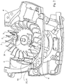
Fig. 1 , partly schematically, shows a combustion engine unit according to the invention, comprising a crankcase, viewed towards the fan wheel side, and a symbolically illustrated carburettor, engine cylinder and muffler, -
Fig. 2 shows a perspective view of the crankcase as well as the fan wheel in a view from the rear/below, -
Fig. 3 shows a detail inFig. 2 in larger scale, -
Fig. 4 shows a frontal view of the crankcase, i.e. towards the clutch side, -
Fig. 5 shows the crankcase towards the side that is directed towards the carburettor, and -
Fig. 6 shows a cross sectional view of the crankcase and the fan wheel along the line VI-VI inFig. 5 . - In all figures, the covers surrounding at least the crankcase and the carburettor have been removed.
- A crankcase according to the preferred embodiment of the invention is generally designated 1 in the drawing figures. On a
fan wheel side 2,Fig. 5 , shown as a frontal view inFig. 1 , there is afan wheel 3 in afan scroll 4,Fig.2 . Thefan wheel 3 is in a conventional way provided withfan blades 5 and forms together with the fan scroll a centrifugal fan, that is driving cooling air out through anoutlet section 6 in thefan scroll 4 for cooling of primarily an engine cylinder 8 (schematically shown inFig. 1 ), that is an integral part of a combustion engine. - The
fan wheel 3 is, when the engine is running, rotated by acrankshaft 10, that extends through thecrankcase 1. On the side, here designatedclutch side 11,Fig. 5 , that is located opposite thefan wheel side 2, there is a not shown centrifugal clutch for the crankshaft's 10 driving of a working tool, for example a rotating saw blade on a brushcutter via a transmission. The not shown centrifugal clutch is, when assembled, arranged in aclutch housing 12, that, when assembled, normally is covered by a not shown clutch cover. - The
crankcase 1 forms a part of a combustion engine unit, generally designated 14 inFig. 1 . Included inunit 14 are, apart fromcrankcase 1 andcylinder 8, also a carburettor 15 or other arrangement for supply of air/fuel mixture to thecylinder 8 and amuffler 16.Cylinder 8 is connected tocrankcase 1 on one of the sides of the crankcase between thefan wheel side 2 and theclutch side 11, here designatedcylinder connection side 17. Two other sides are designated;carburettor side 18, on which the carburettor 15 is connected andmuffler side 19, on which side themuffler 16 is arranged at a short distance from the crankcase. - A crankcase chamber is designated 20. A
connecting rod 21, that is connected to a not shown piston in the schematically showncylinder 8, extends through a not shown opening in the crankcase wall on thecylinder connection side 17 for driving of thecrankshaft 10 in a conventional way via acrank elbow 22,Fig. 6 . Thecrankshaft 10 is suspended in thecrankcase chamber 20 by means of two main bearings, namely a first main bearing 23 fitted in acrankcase gable 25 on theclutch side 11 and a second main bearing 24 fitted in anopposite crankcase gable 26 on thefan wheel side 2. Themain bearings - Crankcase 1 consists of two
halves 1A and IB,Fig. 6 . Bothhalves 1A and IB, that are separately cast, are joined together to one unit by means of a screw fasteners and are in contact with each other in a contact plane 1C. - According to the invention,
crankcase 1 has double walls in the area of thecrankcase chamber 20 on thecarburettor side 18,Fig. 6 . An inner wall is designated 30 and an outer wall is designated 31. Between theinner wall 30 and theouter wall 31 there is acooling air duct 32, that extends outside thecrankcase chamber 20 within the area of at least essentially the entire part of thecarburettor side 18 that is exposed towards the carburettor 15, i.e. that corresponds to the extent of the carburettor. InFig. 5 this area has been indicated by broken lines and designated 33. In theoutlet section 6 of the fan scroll 4 there is an inlet opening 35,Fig. 1 andFig. 6 , to anantechamber 36 to thecooling air duct 32. The inner and outer walls of theantechamber 36 are designated 37 and 38 respectively. Theinner wall 37 forms an extension of theinner wall 30 ofchannel 32. Over the inlet opening 35 there is a nozzle, that forms anair inlet cover 40 made of moulding plastic, recessed in anindentation 47 in the bottom of theoutlet section 6, the indentation adapted to the shape of thecover 40. An inlet opening 41 in thecover 40 is directed against the direction of air flow in theoutlet section 6. The plane of the inlet opening 41,Fig 3 , can be, but need not be, essentially perpendicular to the bottom wall of fan scroll 4 in the area ofoutlet section 6. From the inlet opening 41, a couple of side walls extend backwards, curved so that oneside 42 connects to the fan wheel's 3 circular curvature and so that theopposite side 43 connects to the widening curvature of the outlet section. Theroof 44 of theair inlet cover 40 is initially almost plane and is then curving down towards the bottom wall ofoutlet section 6. On the roof of theair inlet cover 40, there is aflange 46, that continuously extends in a curvature backwards in theoutlet section 6 behind the cover. Thecover 40 is bolted in the bottom wall of theoutlet section 6. A screw hole in the wall and aseat 45 for the screw head is shown inFig. 3 . - In its other end, the
cooling air duct 32 is provided with an outlet opening 50 in thecrankcase gable 25 on the clutch side,Fig. 4 andFig. 6 . In thesame crankcase gable 25 on the clutch side, inside the not shown centrifugal clutch, at a distance from the outlet opening 50, anevacuation opening 51 is arranged for guiding the cooling air away from thehousing 12 on the clutch side, that is covered by the not shown centrifugal clutch, within whicharea 12 also the outlet opening 50 of thecooling air duct 32 is located. - The described
unit 14 and the arrangement work in the following manner. With the engine operating, thefan wheel 3 is driven by thecrankshaft 10. Thecrankcase chamber 20, including its walls andbearings cylinder 8. At the same time, however, the inner andouter crankcase walls fan blades 5 into thecover 40 and further via theantechamber 36 into the coolingair duct 32, that prevents itswalls fan blades 5 of the fan wheel is driven into thecover 40 and further through thechamber 36 and coolingair duct 32. The main flow is blown out through the mouth of theoutlet section 6 in order to cool the outside ofcylinder 8 in a normal manner. The arc-shapedflange 46 on the roof of the cover and behind thecover 40 is thus contributing to direct the airflow and create desired fan operation in the outlet section for cooling of thecylinder 8. From the coolingair duct 32, the diverted cooling air flows out through opening 50 in theclutch housing 12 and contributes to cool the centrifugal clutch under the not shown clutch cover and finally leaves theclutch housing 12 through the evacuation opening 51 to be spread into the ambient air. While the engine is running, the cooling of theinner wall 30 on the carburettor side contributes to keep the temperature of thecrankcase chamber 20 at a moderately high level, with the intent to prevent themain bearings - As mentioned in the introduction, shorter operational interruptions with this type of machines can often be an inconvenient problem due to heating through radiation from the crankcase wall on the carburettor side of the crankcase. The
outer wall 31 in the area of thecrankcase chamber 20 has however been continuously cooled by means of cooling air that flows through the coolingair duct 32, which prevents or at least strongly counteracts the heating of the carburettor due to the after-heat from the crankcase while the engine and consequently the fan wheel and its fan blades are at a standstill. Theinner wall 30 in the area of the coolingair duct 32 has also been cooled during the operation of the machine, which also counteracts damage particularly to themain bearings
Claims (10)
- An air-cooled combustion engine unit for a hand-held working machine, such as a brushcutter or a trimmer comprising at least an engine cylinder (8), a crankcase (1) a carburettor (15) and a muffler (16), the crankcase (1) comprising a crankcase chamber (20), a fan wheel side (2) with a fan scroll (4) and a fan wheel (3) with fan blades (5) arranged in the fan scroll (4), a clutch side (11) opposite the fan wheel side (2) and, between the fan wheel side (2) and the clutch side (11), a number of crankcase walls, a cylinder connection side (17) with opening for at least a connecting rod (21), and a carburettor side (18) characterized in that the engine is a two-stroke engine of the crankcase scavenging type, i.e. that at least the combustion air for the engine flows through its crankcase and in that, through a crankcase wall on at least said carburettor side (18) between the fan wheel side (2) and the clutch side (11), one or more cooling ducts (32) extends between one or more inlet openings (35) for cooling air in the fan scroll (4) and one or more outlet openings (50) for the cooling air exiting in a clutch housing (12), for cooling of the wall on said carburettor side (18) between the fan wheel side (2) and the clutch side (11).
- A combustion engine unit according to claim 1, characterized in that the crankcase wall (30,31) on said carburettor side has double walls, comprising an inner wall (30) directed towards a crankcase chamber (20) and an outer wall (31), whereby a space between the walls (30,31) form a slit shaped cooling duct (32).
- A combustion engine unit according to claim 1 or 2, characterized in that said one or more inlet openings (35) for cooling air in the fan scroll are covered by an inlet cover (40) for cooling air for diversion of a sub-flow of the air, that, by the fan wheel, is blown out through the outlet section of the fan scroll.
- A combustion engine unit according to claim 3, characterized in that said inlet cover is arranged in the outlet section (6) of the fan scroll.
- A combustion engine unit according to claim 4, characterized in that the mouth of the inlet cover is essentially transversely located in relation to the bottom of the fan scroll in the area of the outlet section (6).
- A combustion engine unit according to any one of the claims 1-5, characterized in that an evacuation opening (51) is arranged at the bottom of the clutch housing (12) at a distance from said one or more outlet openings (50) for the cooling air, for evacuation of the spent cooling air from the clutch housing.
- A combustion engine unit according to claims 1-2, characterized in that the cooling air duct (32) extends outside the crankcase chamber (20) within the area of the entire part of the carburettor side (18) that is exposed towards the carburettor.
- A combustion engine unit according to any one of claims 1-7, characterized in that said one or more cooling ducts in the crankcase wall extend along an area (33) of the crankcase wall, that corresponds to at least a significant portion of the extent of the carburettor.
- A combustion engine unit according to any one of the claims 1-8, characterized in that a sub-flow of the air that is blown out by the fan wheel through the outlet section (6) of the fan scroll is diverted to said one or more cooling ducts, while the remaining air is blown out through the outlet section for cooling of the engine cylinder.
- A handheld working machine, such as a brushcutter or a trimmer, comprising a rotating working tool, for example a saw blade, for clearing of smaller trees, bushes, brush and/or grass, characterized in that the rotating working tool is driven by a combustion engine unit according to any one of the claims 1-9.
Applications Claiming Priority (1)
| Application Number | Priority Date | Filing Date | Title |
|---|---|---|---|
| PCT/SE2006/001273 WO2008057015A1 (en) | 2006-11-08 | 2006-11-08 | Crankcase and internal combustion engine unit |
Publications (3)
| Publication Number | Publication Date |
|---|---|
| EP2079919A1 EP2079919A1 (en) | 2009-07-22 |
| EP2079919A4 EP2079919A4 (en) | 2010-05-12 |
| EP2079919B1 true EP2079919B1 (en) | 2019-01-16 |
Family
ID=39364750
Family Applications (1)
| Application Number | Title | Priority Date | Filing Date |
|---|---|---|---|
| EP06812996.4A Active EP2079919B1 (en) | 2006-11-08 | 2006-11-08 | Crankcase and internal combustion engine unit |
Country Status (2)
| Country | Link |
|---|---|
| EP (1) | EP2079919B1 (en) |
| WO (1) | WO2008057015A1 (en) |
Families Citing this family (2)
| Publication number | Priority date | Publication date | Assignee | Title |
|---|---|---|---|---|
| DE202008003781U1 (en) * | 2008-03-18 | 2009-08-13 | Dolmar Gmbh | Device for cleaning intake air |
| FR3016396A1 (en) * | 2014-01-13 | 2015-07-17 | Rdmo | PUMP BODY INTEGRATED IN THE CASING OF A LIQUID COOLING ENGINE |
Family Cites Families (9)
| Publication number | Priority date | Publication date | Assignee | Title |
|---|---|---|---|---|
| DE317842C (en) * | ||||
| US3747649A (en) * | 1971-02-08 | 1973-07-24 | Outboard Marine Corp | Crankshaft magneto system |
| DE19618669A1 (en) * | 1996-05-09 | 1997-11-13 | Stihl Maschf Andreas | Hand held tool e.g. cutters, chain saw, disk grinder etc. |
| JPH1077835A (en) * | 1996-08-30 | 1998-03-24 | Fuji Heavy Ind Ltd | Cooling device for air-cooled engine |
| US6314922B1 (en) * | 1998-07-23 | 2001-11-13 | Andreas Stihl Ag & Co. | Hand-held working tool |
| JP3803526B2 (en) * | 2000-03-16 | 2006-08-02 | 本田技研工業株式会社 | Side valve engine |
| DE10021705B4 (en) * | 2000-05-04 | 2018-01-11 | Andreas Stihl Ag & Co. | Hand-held implement |
| JP2002371846A (en) * | 2001-06-15 | 2002-12-26 | Mitsubishi Heavy Ind Ltd | Cooling device for air cooled engine |
| JP2004324420A (en) * | 2003-04-21 | 2004-11-18 | Kioritz Corp | Air-cooled 4-cycle engine |
-
2006
- 2006-11-08 EP EP06812996.4A patent/EP2079919B1/en active Active
- 2006-11-08 WO PCT/SE2006/001273 patent/WO2008057015A1/en not_active Ceased
Also Published As
| Publication number | Publication date |
|---|---|
| WO2008057015A1 (en) | 2008-05-15 |
| EP2079919A1 (en) | 2009-07-22 |
| EP2079919A4 (en) | 2010-05-12 |
Similar Documents
| Publication | Publication Date | Title |
|---|---|---|
| US6640443B2 (en) | Manually guided implement | |
| US9010299B2 (en) | Engine tool | |
| JP5608452B2 (en) | Work machine engine and work machine using the same | |
| JP4280142B2 (en) | Vertical liquid cooling engine | |
| CN102428255A (en) | Four-cycle engine, bush cutter and engine-driven tool having same | |
| JP5872775B2 (en) | Brush cutter | |
| US5533869A (en) | Power tool exhaust cooling system | |
| US20140000537A1 (en) | Power Tool | |
| JP5819160B2 (en) | Backpack type work machine | |
| EP3263857B1 (en) | Engine and engine-driven working machine | |
| EP2079919A1 (en) | Crankcase and internal combustion engine unit | |
| JP3754610B2 (en) | Foreign matter entrainment prevention device for working engine | |
| CN102562249B (en) | Cooling structure in air-cooled combustion engine | |
| CN212306156U (en) | Grass trimmer operation end and grass trimmer | |
| JP3819591B2 (en) | Air-cooled engine | |
| JP5825951B2 (en) | Engine for portable work machines | |
| JP3726065B2 (en) | Engine cooling structure | |
| CN111148891B (en) | Universal engine | |
| JPH0744735Y2 (en) | Wind guide structure of in-line 2-cylinder engine | |
| US20250065485A1 (en) | Work apparatus with internal combustion engine | |
| JP5263709B2 (en) | 2-cycle engine | |
| JP6572678B2 (en) | Engine and engine working machine | |
| CN111075549B (en) | Universal engine | |
| CN110805484B (en) | Universal engine | |
| JP3441209B2 (en) | Muffler protector structure for work machine engine |
Legal Events
| Date | Code | Title | Description |
|---|---|---|---|
| PUAI | Public reference made under article 153(3) epc to a published international application that has entered the european phase |
Free format text: ORIGINAL CODE: 0009012 |
|
| 17P | Request for examination filed |
Effective date: 20090419 |
|
| AK | Designated contracting states |
Kind code of ref document: A1 Designated state(s): AT BE BG CH CY CZ DE DK EE ES FI FR GB GR HU IE IS IT LI LT LU LV MC NL PL PT RO SE SI SK TR |
|
| A4 | Supplementary search report drawn up and despatched |
Effective date: 20100413 |
|
| DAX | Request for extension of the european patent (deleted) | ||
| 17Q | First examination report despatched |
Effective date: 20160502 |
|
| STAA | Information on the status of an ep patent application or granted ep patent |
Free format text: STATUS: EXAMINATION IS IN PROGRESS |
|
| GRAP | Despatch of communication of intention to grant a patent |
Free format text: ORIGINAL CODE: EPIDOSNIGR1 |
|
| STAA | Information on the status of an ep patent application or granted ep patent |
Free format text: STATUS: GRANT OF PATENT IS INTENDED |
|
| INTG | Intention to grant announced |
Effective date: 20180802 |
|
| GRAS | Grant fee paid |
Free format text: ORIGINAL CODE: EPIDOSNIGR3 |
|
| GRAA | (expected) grant |
Free format text: ORIGINAL CODE: 0009210 |
|
| STAA | Information on the status of an ep patent application or granted ep patent |
Free format text: STATUS: THE PATENT HAS BEEN GRANTED |
|
| AK | Designated contracting states |
Kind code of ref document: B1 Designated state(s): AT BE BG CH CY CZ DE DK EE ES FI FR GB GR HU IE IS IT LI LT LU LV MC NL PL PT RO SE SI SK TR |
|
| REG | Reference to a national code |
Ref country code: GB Ref legal event code: FG4D |
|
| REG | Reference to a national code |
Ref country code: CH Ref legal event code: EP |
|
| REG | Reference to a national code |
Ref country code: IE Ref legal event code: FG4D |
|
| REG | Reference to a national code |
Ref country code: DE Ref legal event code: R096 Ref document number: 602006057320 Country of ref document: DE |
|
| REG | Reference to a national code |
Ref country code: AT Ref legal event code: REF Ref document number: 1089877 Country of ref document: AT Kind code of ref document: T Effective date: 20190215 |
|
| REG | Reference to a national code |
Ref country code: NL Ref legal event code: MP Effective date: 20190116 |
|
| REG | Reference to a national code |
Ref country code: LT Ref legal event code: MG4D |
|
| PG25 | Lapsed in a contracting state [announced via postgrant information from national office to epo] |
Ref country code: NL Free format text: LAPSE BECAUSE OF FAILURE TO SUBMIT A TRANSLATION OF THE DESCRIPTION OR TO PAY THE FEE WITHIN THE PRESCRIBED TIME-LIMIT Effective date: 20190116 |
|
| REG | Reference to a national code |
Ref country code: AT Ref legal event code: MK05 Ref document number: 1089877 Country of ref document: AT Kind code of ref document: T Effective date: 20190116 |
|
| PG25 | Lapsed in a contracting state [announced via postgrant information from national office to epo] |
Ref country code: PT Free format text: LAPSE BECAUSE OF FAILURE TO SUBMIT A TRANSLATION OF THE DESCRIPTION OR TO PAY THE FEE WITHIN THE PRESCRIBED TIME-LIMIT Effective date: 20190516 Ref country code: ES Free format text: LAPSE BECAUSE OF FAILURE TO SUBMIT A TRANSLATION OF THE DESCRIPTION OR TO PAY THE FEE WITHIN THE PRESCRIBED TIME-LIMIT Effective date: 20190116 Ref country code: FI Free format text: LAPSE BECAUSE OF FAILURE TO SUBMIT A TRANSLATION OF THE DESCRIPTION OR TO PAY THE FEE WITHIN THE PRESCRIBED TIME-LIMIT Effective date: 20190116 Ref country code: LT Free format text: LAPSE BECAUSE OF FAILURE TO SUBMIT A TRANSLATION OF THE DESCRIPTION OR TO PAY THE FEE WITHIN THE PRESCRIBED TIME-LIMIT Effective date: 20190116 Ref country code: PL Free format text: LAPSE BECAUSE OF FAILURE TO SUBMIT A TRANSLATION OF THE DESCRIPTION OR TO PAY THE FEE WITHIN THE PRESCRIBED TIME-LIMIT Effective date: 20190116 Ref country code: SE Free format text: LAPSE BECAUSE OF FAILURE TO SUBMIT A TRANSLATION OF THE DESCRIPTION OR TO PAY THE FEE WITHIN THE PRESCRIBED TIME-LIMIT Effective date: 20190116 |
|
| PG25 | Lapsed in a contracting state [announced via postgrant information from national office to epo] |
Ref country code: BG Free format text: LAPSE BECAUSE OF FAILURE TO SUBMIT A TRANSLATION OF THE DESCRIPTION OR TO PAY THE FEE WITHIN THE PRESCRIBED TIME-LIMIT Effective date: 20190416 Ref country code: GR Free format text: LAPSE BECAUSE OF FAILURE TO SUBMIT A TRANSLATION OF THE DESCRIPTION OR TO PAY THE FEE WITHIN THE PRESCRIBED TIME-LIMIT Effective date: 20190417 Ref country code: IS Free format text: LAPSE BECAUSE OF FAILURE TO SUBMIT A TRANSLATION OF THE DESCRIPTION OR TO PAY THE FEE WITHIN THE PRESCRIBED TIME-LIMIT Effective date: 20190516 Ref country code: LV Free format text: LAPSE BECAUSE OF FAILURE TO SUBMIT A TRANSLATION OF THE DESCRIPTION OR TO PAY THE FEE WITHIN THE PRESCRIBED TIME-LIMIT Effective date: 20190116 |
|
| REG | Reference to a national code |
Ref country code: DE Ref legal event code: R097 Ref document number: 602006057320 Country of ref document: DE |
|
| PG25 | Lapsed in a contracting state [announced via postgrant information from national office to epo] |
Ref country code: CZ Free format text: LAPSE BECAUSE OF FAILURE TO SUBMIT A TRANSLATION OF THE DESCRIPTION OR TO PAY THE FEE WITHIN THE PRESCRIBED TIME-LIMIT Effective date: 20190116 Ref country code: RO Free format text: LAPSE BECAUSE OF FAILURE TO SUBMIT A TRANSLATION OF THE DESCRIPTION OR TO PAY THE FEE WITHIN THE PRESCRIBED TIME-LIMIT Effective date: 20190116 Ref country code: IT Free format text: LAPSE BECAUSE OF FAILURE TO SUBMIT A TRANSLATION OF THE DESCRIPTION OR TO PAY THE FEE WITHIN THE PRESCRIBED TIME-LIMIT Effective date: 20190116 Ref country code: SK Free format text: LAPSE BECAUSE OF FAILURE TO SUBMIT A TRANSLATION OF THE DESCRIPTION OR TO PAY THE FEE WITHIN THE PRESCRIBED TIME-LIMIT Effective date: 20190116 Ref country code: DK Free format text: LAPSE BECAUSE OF FAILURE TO SUBMIT A TRANSLATION OF THE DESCRIPTION OR TO PAY THE FEE WITHIN THE PRESCRIBED TIME-LIMIT Effective date: 20190116 Ref country code: AT Free format text: LAPSE BECAUSE OF FAILURE TO SUBMIT A TRANSLATION OF THE DESCRIPTION OR TO PAY THE FEE WITHIN THE PRESCRIBED TIME-LIMIT Effective date: 20190116 Ref country code: EE Free format text: LAPSE BECAUSE OF FAILURE TO SUBMIT A TRANSLATION OF THE DESCRIPTION OR TO PAY THE FEE WITHIN THE PRESCRIBED TIME-LIMIT Effective date: 20190116 |
|
| PLBE | No opposition filed within time limit |
Free format text: ORIGINAL CODE: 0009261 |
|
| STAA | Information on the status of an ep patent application or granted ep patent |
Free format text: STATUS: NO OPPOSITION FILED WITHIN TIME LIMIT |
|
| 26N | No opposition filed |
Effective date: 20191017 |
|
| PG25 | Lapsed in a contracting state [announced via postgrant information from national office to epo] |
Ref country code: SI Free format text: LAPSE BECAUSE OF FAILURE TO SUBMIT A TRANSLATION OF THE DESCRIPTION OR TO PAY THE FEE WITHIN THE PRESCRIBED TIME-LIMIT Effective date: 20190116 |
|
| PG25 | Lapsed in a contracting state [announced via postgrant information from national office to epo] |
Ref country code: TR Free format text: LAPSE BECAUSE OF FAILURE TO SUBMIT A TRANSLATION OF THE DESCRIPTION OR TO PAY THE FEE WITHIN THE PRESCRIBED TIME-LIMIT Effective date: 20190116 |
|
| REG | Reference to a national code |
Ref country code: CH Ref legal event code: PL |
|
| PG25 | Lapsed in a contracting state [announced via postgrant information from national office to epo] |
Ref country code: MC Free format text: LAPSE BECAUSE OF FAILURE TO SUBMIT A TRANSLATION OF THE DESCRIPTION OR TO PAY THE FEE WITHIN THE PRESCRIBED TIME-LIMIT Effective date: 20190116 Ref country code: LU Free format text: LAPSE BECAUSE OF NON-PAYMENT OF DUE FEES Effective date: 20191108 Ref country code: LI Free format text: LAPSE BECAUSE OF NON-PAYMENT OF DUE FEES Effective date: 20191130 Ref country code: CH Free format text: LAPSE BECAUSE OF NON-PAYMENT OF DUE FEES Effective date: 20191130 |
|
| REG | Reference to a national code |
Ref country code: BE Ref legal event code: MM Effective date: 20191130 |
|
| GBPC | Gb: european patent ceased through non-payment of renewal fee |
Effective date: 20191108 |
|
| PG25 | Lapsed in a contracting state [announced via postgrant information from national office to epo] |
Ref country code: FR Free format text: LAPSE BECAUSE OF NON-PAYMENT OF DUE FEES Effective date: 20191130 Ref country code: IE Free format text: LAPSE BECAUSE OF NON-PAYMENT OF DUE FEES Effective date: 20191108 Ref country code: GB Free format text: LAPSE BECAUSE OF NON-PAYMENT OF DUE FEES Effective date: 20191108 |
|
| PG25 | Lapsed in a contracting state [announced via postgrant information from national office to epo] |
Ref country code: BE Free format text: LAPSE BECAUSE OF NON-PAYMENT OF DUE FEES Effective date: 20191130 |
|
| PG25 | Lapsed in a contracting state [announced via postgrant information from national office to epo] |
Ref country code: CY Free format text: LAPSE BECAUSE OF FAILURE TO SUBMIT A TRANSLATION OF THE DESCRIPTION OR TO PAY THE FEE WITHIN THE PRESCRIBED TIME-LIMIT Effective date: 20190116 |
|
| PG25 | Lapsed in a contracting state [announced via postgrant information from national office to epo] |
Ref country code: HU Free format text: LAPSE BECAUSE OF FAILURE TO SUBMIT A TRANSLATION OF THE DESCRIPTION OR TO PAY THE FEE WITHIN THE PRESCRIBED TIME-LIMIT; INVALID AB INITIO Effective date: 20061108 |
|
| P01 | Opt-out of the competence of the unified patent court (upc) registered |
Effective date: 20230419 |
|
| PGFP | Annual fee paid to national office [announced via postgrant information from national office to epo] |
Ref country code: DE Payment date: 20241014 Year of fee payment: 19 |