EP2078885A1 - Device for purging contaminants from a lubricant pocket of a limited slip differential - Google Patents
Device for purging contaminants from a lubricant pocket of a limited slip differential Download PDFInfo
- Publication number
- EP2078885A1 EP2078885A1 EP20080171756 EP08171756A EP2078885A1 EP 2078885 A1 EP2078885 A1 EP 2078885A1 EP 20080171756 EP20080171756 EP 20080171756 EP 08171756 A EP08171756 A EP 08171756A EP 2078885 A1 EP2078885 A1 EP 2078885A1
- Authority
- EP
- European Patent Office
- Prior art keywords
- differential transmission
- valve element
- lubricant
- assembly
- case
- Prior art date
- Legal status (The legal status is an assumption and is not a legal conclusion. Google has not performed a legal analysis and makes no representation as to the accuracy of the status listed.)
- Granted
Links
- 239000000314 lubricant Substances 0.000 title claims abstract description 43
- 238000010926 purge Methods 0.000 title claims abstract description 12
- 239000000356 contaminant Substances 0.000 title claims abstract description 9
- 230000005540 biological transmission Effects 0.000 claims abstract description 58
- 230000004044 response Effects 0.000 claims abstract description 5
- 239000012530 fluid Substances 0.000 claims description 5
- 230000009699 differential effect Effects 0.000 claims description 3
- 230000009471 action Effects 0.000 claims description 2
- 230000000670 limiting effect Effects 0.000 claims description 2
- 230000004913 activation Effects 0.000 claims 1
- 230000002708 enhancing effect Effects 0.000 claims 1
- 230000033001 locomotion Effects 0.000 description 4
- 238000005461 lubrication Methods 0.000 description 4
- 230000000712 assembly Effects 0.000 description 2
- 238000000429 assembly Methods 0.000 description 2
- 230000001050 lubricating effect Effects 0.000 description 2
- 230000002411 adverse Effects 0.000 description 1
- 238000001816 cooling Methods 0.000 description 1
- 230000007812 deficiency Effects 0.000 description 1
- 230000005484 gravity Effects 0.000 description 1
- 230000007774 longterm Effects 0.000 description 1
- 239000000463 material Substances 0.000 description 1
- 230000007246 mechanism Effects 0.000 description 1
- 239000002184 metal Substances 0.000 description 1
- 238000000034 method Methods 0.000 description 1
- 238000012986 modification Methods 0.000 description 1
- 230000004048 modification Effects 0.000 description 1
- 230000003071 parasitic effect Effects 0.000 description 1
- 230000036961 partial effect Effects 0.000 description 1
- 230000009467 reduction Effects 0.000 description 1
- 230000002829 reductive effect Effects 0.000 description 1
- 230000000717 retained effect Effects 0.000 description 1
- 230000000979 retarding effect Effects 0.000 description 1
- 230000007704 transition Effects 0.000 description 1
Images



Classifications
-
- F—MECHANICAL ENGINEERING; LIGHTING; HEATING; WEAPONS; BLASTING
- F16—ENGINEERING ELEMENTS AND UNITS; GENERAL MEASURES FOR PRODUCING AND MAINTAINING EFFECTIVE FUNCTIONING OF MACHINES OR INSTALLATIONS; THERMAL INSULATION IN GENERAL
- F16H—GEARING
- F16H48/00—Differential gearings
- F16H48/38—Constructional details
-
- F—MECHANICAL ENGINEERING; LIGHTING; HEATING; WEAPONS; BLASTING
- F16—ENGINEERING ELEMENTS AND UNITS; GENERAL MEASURES FOR PRODUCING AND MAINTAINING EFFECTIVE FUNCTIONING OF MACHINES OR INSTALLATIONS; THERMAL INSULATION IN GENERAL
- F16H—GEARING
- F16H57/00—General details of gearing
- F16H57/04—Features relating to lubrication or cooling or heating
- F16H57/0467—Elements of gearings to be lubricated, cooled or heated
- F16H57/0469—Bearings or seals
-
- F—MECHANICAL ENGINEERING; LIGHTING; HEATING; WEAPONS; BLASTING
- F16—ENGINEERING ELEMENTS AND UNITS; GENERAL MEASURES FOR PRODUCING AND MAINTAINING EFFECTIVE FUNCTIONING OF MACHINES OR INSTALLATIONS; THERMAL INSULATION IN GENERAL
- F16H—GEARING
- F16H57/00—General details of gearing
- F16H57/04—Features relating to lubrication or cooling or heating
- F16H57/0402—Cleaning of lubricants, e.g. filters or magnets
-
- F—MECHANICAL ENGINEERING; LIGHTING; HEATING; WEAPONS; BLASTING
- F16—ENGINEERING ELEMENTS AND UNITS; GENERAL MEASURES FOR PRODUCING AND MAINTAINING EFFECTIVE FUNCTIONING OF MACHINES OR INSTALLATIONS; THERMAL INSULATION IN GENERAL
- F16H—GEARING
- F16H57/00—General details of gearing
- F16H57/04—Features relating to lubrication or cooling or heating
- F16H57/048—Type of gearings to be lubricated, cooled or heated
- F16H57/0482—Gearings with gears having orbital motion
- F16H57/0483—Axle or inter-axle differentials
-
- F—MECHANICAL ENGINEERING; LIGHTING; HEATING; WEAPONS; BLASTING
- F16—ENGINEERING ELEMENTS AND UNITS; GENERAL MEASURES FOR PRODUCING AND MAINTAINING EFFECTIVE FUNCTIONING OF MACHINES OR INSTALLATIONS; THERMAL INSULATION IN GENERAL
- F16H—GEARING
- F16H61/00—Control functions within control units of change-speed- or reversing-gearings for conveying rotary motion ; Control of exclusively fluid gearing, friction gearing, gearings with endless flexible members or other particular types of gearing
- F16H61/38—Control of exclusively fluid gearing
- F16H61/40—Control of exclusively fluid gearing hydrostatic
- F16H61/4165—Control of cooling or lubricating
-
- F—MECHANICAL ENGINEERING; LIGHTING; HEATING; WEAPONS; BLASTING
- F16—ENGINEERING ELEMENTS AND UNITS; GENERAL MEASURES FOR PRODUCING AND MAINTAINING EFFECTIVE FUNCTIONING OF MACHINES OR INSTALLATIONS; THERMAL INSULATION IN GENERAL
- F16H—GEARING
- F16H57/00—General details of gearing
- F16H57/04—Features relating to lubrication or cooling or heating
- F16H57/042—Guidance of lubricant
- F16H57/043—Guidance of lubricant within rotary parts, e.g. axial channels or radial openings in shafts
-
- F—MECHANICAL ENGINEERING; LIGHTING; HEATING; WEAPONS; BLASTING
- F16—ENGINEERING ELEMENTS AND UNITS; GENERAL MEASURES FOR PRODUCING AND MAINTAINING EFFECTIVE FUNCTIONING OF MACHINES OR INSTALLATIONS; THERMAL INSULATION IN GENERAL
- F16H—GEARING
- F16H57/00—General details of gearing
- F16H57/04—Features relating to lubrication or cooling or heating
- F16H57/0467—Elements of gearings to be lubricated, cooled or heated
- F16H57/0473—Friction devices, e.g. clutches or brakes
-
- Y—GENERAL TAGGING OF NEW TECHNOLOGICAL DEVELOPMENTS; GENERAL TAGGING OF CROSS-SECTIONAL TECHNOLOGIES SPANNING OVER SEVERAL SECTIONS OF THE IPC; TECHNICAL SUBJECTS COVERED BY FORMER USPC CROSS-REFERENCE ART COLLECTIONS [XRACs] AND DIGESTS
- Y10—TECHNICAL SUBJECTS COVERED BY FORMER USPC
- Y10T—TECHNICAL SUBJECTS COVERED BY FORMER US CLASSIFICATION
- Y10T137/00—Fluid handling
- Y10T137/2496—Self-proportioning or correlating systems
- Y10T137/2559—Self-controlled branched flow systems
- Y10T137/2562—Dividing and recombining
-
- Y—GENERAL TAGGING OF NEW TECHNOLOGICAL DEVELOPMENTS; GENERAL TAGGING OF CROSS-SECTIONAL TECHNOLOGIES SPANNING OVER SEVERAL SECTIONS OF THE IPC; TECHNICAL SUBJECTS COVERED BY FORMER USPC CROSS-REFERENCE ART COLLECTIONS [XRACs] AND DIGESTS
- Y10—TECHNICAL SUBJECTS COVERED BY FORMER USPC
- Y10T—TECHNICAL SUBJECTS COVERED BY FORMER US CLASSIFICATION
- Y10T137/00—Fluid handling
- Y10T137/2496—Self-proportioning or correlating systems
- Y10T137/2559—Self-controlled branched flow systems
- Y10T137/2574—Bypass or relief controlled by main line fluid condition
- Y10T137/2579—Flow rate responsive
- Y10T137/2589—Pilot valve operated
Definitions
- the invention relates to a device for purging contaminants from lubricant pockets of a limited slip differential transmission. Furthermore the invention relates to a differential transmission with such a device.
- Transmissions of this type have a carrier that receives input from a pinion gear and provides a drive for planet gears meshing with sun gears attached to output shafts connected to wheels on opposite sides of a vehicle.
- the limited slip assembly involves retarding the pure differential movement of the output shafts to the different wheels.
- a limited slip assembly When a limited slip assembly is employed in such a transmission, it is usually in the form of a series of clutch disk surfaces alternately connected to a carrier for the differential and to one of the output shafts.
- the chamber for such disks forms a pocket for lubricant. As such, any debris generated by engagement and disengagement of the clutch disks tends to collect in the pocket, thereby having an adverse impact on the long term durability of the transmission.
- the invention in one form includes a device for purging contaminants from a lubricant pocket of a limited slip differential transmission having a sealed, pressurized system for rotating and inter-engaging parts of the differential transmission.
- the device comprises a valve element displaceable between a first and second position in response to a control feature of said differential transmission. Passages are formed in the differential transmission between the lubricant pockets and a sump chamber for said differential transmission.
- the valve element is interposed in the passages and configured to permit flow from said lubricant pocket to said sump chamber as said valve element displaces between said first and second position.
- the invention in another form, includes a differential transmission having a case journaled for rotation about a main axis.
- First and second rotatable output shafts are received by the case and journaled about said main axis and have first and second bevel sun gears affixed thereto, respectively.
- a plurality of bevel planet gears each rotatably mounted on the case in meshing engagement with the first and second bevel sun gears.
- An assembly is provided for selectively engaging said case and one of said sun gears for limiting differential action.
- a system is provided for supplying pressurized lubricant to journal the case, gears and the selectively engageable assembly, the differential transmission being arranged to seal the case, gears and selectively engageable assembly.
- the differential transmission has a passage from the selectively engageable assembly to the sump chamber.
- a valve element is interposed in the passage and displaceable between a first and second position in response to engagement and disengagement of the selectively engageable assembly.
- the valve element is configured to permit flow of pressurized lubricant from the selectively engageable assembly to the sump chamber as said valve element is displaceable between said first and second positions to purge contaminants from the selectively engageable assembly.
- Fig. 1 shows a differential transmission 10 used to transfer the torque output of a pinion gear (not shown) to a pair of output shafts 12 and 14.
- Differential transmission 10 has a central housing 16 and a pair of end plates 18 and 20 forming part of a housing for the transmission 10. Additional transmission features such as speed reduction, brakes, etc. are not shown to simplify the discussion of the present invention.
- the differential transmission 10 has a closed system (which is indicated in Fig.
- a carrier 38 is journaled by means of bearing assemblies 28 and 30, respectively.
- Output shafts 12 and 14 have secured to their ends bevel sun gears 32 and 34, respectively.
- Sun gears 32 and 34 intermesh with a plurality of bevel planet gears 36 journaled for rotation on the carrier 38.
- Carrier 38 provides a mounting for a pinion gear 40 that meshes with the pinion gear (not shown) by means of appropriate fasteners 42 that extend through housing 37, also connected to carrier 38.
- the carrier 38, planet gears 36 and sun gears 32 and 34 provide a differential rotation so that the output shafts 12 and 14 may rotate at different RPMs when a vehicle in which the differential transmission 10 is mounted navigates a corner.
- differential transmission 10 When the differential transmission 10 is installed in an agricultural or off-road industrial vehicle, there are frequently times when traction on one or more of the wheels powered by output shafts 12 and 14 is reduced which causes a normal differential to send all the power to the wheel that has the greatest velocity. In order to minimize this condition, a limited slip differential assembly 44 is employed.
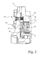
- Limited slip differential assembly 44 is shown in greater detail in Fig. 2 in which a series of clutch disks 46 and 48 are interdigitated and respectively fixed to the carrier 38 and the one of the sun gear 32.
- the clutch disks 46 and 48 are normally held in a position where they slide relative to one another except when an operational situation requires that a limited slip condition be induced.
- a metal diaphragm 50 is displaced against the pack of clutch disks 46 and 48 to cause them to reduce relative rotation between carrier 38 and sun gear 32 to thereby minimize the differential action.
- Annular diaphragm 50 may be actuated by any one of a number means but as herein shown it is actuated by pressure within chamber 52 to urge the diaphragm 50 to the right as shown in Fig. 2 to engage the clutch disks 46 and 48.
- the differential transmission 10 is of the closed type where pressure to the bearings 28 and 30, gears 32, 34 and 36, and clutch disks 46 and 48 is supplied through inlet 26 to provide a constant emersion and lubricant to enable journaling and to remove heat from the gears 32, 34 and 36 meshing and the friction caused by operation under load. While the bearings 28 and 30 and other elements in the differential transmission 10 have a flow of lubricant to the sump chamber 22, the clutch disks 46 and 48 are in a lubricant pocket 54 from which there is no natural flow of lubricant, particularly at the outer periphery thereof.
- a system for purging the lubricant pocket 54 from lubricating fluid is indicated generally at reference sign 56.
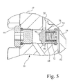
- the system indicated at 56 is shown particularly in Figs. 3 , 4 and 5 .
- the system 56 includes a radially outward passage 58 in housing 37 connected to an annular groove 60 and an annular passage 62 to the outer periphery of the lubricant pocket 54.
- a spool valve 64 is displaceable in a bore 65 that intersects annular groove 60 and annular passage 62. Spool valve 64 is retained within the bore 65 by an appropriate cap screw 66 threaded into housing 37 and sealed by means of o-ring 68.
- Spool valve 64 has an interior recess 70 receiving a spring 72 that urges valve element 64 against cap screw 66.
- An appropriate retaining element 74 is positioned in bore 64 to provide an abutment for spring 72.
- Valve element 64 has a port 76 positioned so that when valve element 64 is intermediate the position illustrated in Fig. 3 and the position shown in Fig. 5 , port 76 registers with groove 60 and permits pressurized lubricant to flow from passage 62 through the interior recess 70 of valve element 64 through groove 60 out radially outward passage 58. This position is shown in detail in Fig. 4 showing the establishment of the flow path to the exterior.
- valve element 64 is displaced to the position permitting a purging of the pressurized lubricant by pressure acting on the end 78 of spool valve 64. This pressure is transmitted to the end 78 of spool valve 64 by a passage 80 connected to chamber 52 providing the actuation for the clutch disks 46 and 48 to minimize relative slippage. Although it is illustrated as having hydraulic pressure to actuate the pack of clutch disks 46 and 48, and therefore the movement of the spool valve 64 to permit flow of pressurized fluid. It should be apparent to those skilled in the art that other forms of actuation may be employed with equal results.
- the transmission 10 operates as a pure differential transmission in which case the clutch disks 46 and 48 are slipping relative to one another and the valve element 64 is in the position illustrated in Fig. 3 .
- pressure is applied to chamber 52 to move annular diaphragm 50 to engage clutch disks 46 and 48 to limit the slippage of the differential transmission 10.
- the pressure in passage 80 applies across the end 78 urging valve element 64 to the position illustrated in Fig. 5 .
- the valve element 64 causes port 76 to align with groove 60 thus permitting a flow of pressurized fluid radially outward through passage 58 and finally to the sump chamber 22.
Landscapes
- Engineering & Computer Science (AREA)
- General Engineering & Computer Science (AREA)
- Mechanical Engineering (AREA)
- General Details Of Gearings (AREA)
- Retarders (AREA)
- Hydraulic Clutches, Magnetic Clutches, Fluid Clutches, And Fluid Joints (AREA)
- Mechanical Operated Clutches (AREA)
Abstract
Description
- The invention relates to a device for purging contaminants from lubricant pockets of a limited slip differential transmission. Furthermore the invention relates to a differential transmission with such a device.
- Differential transmissions have been in existence since the early 30's and particularly with a limited slip assembly that enables transfer of applied torque from a wheel that is slipping to a wheel that has traction. Transmissions of this type have a carrier that receives input from a pinion gear and provides a drive for planet gears meshing with sun gears attached to output shafts connected to wheels on opposite sides of a vehicle. The limited slip assembly involves retarding the pure differential movement of the output shafts to the different wheels.
- In the past, such differential transmissions have been lubricated by what is known as a splash lubrication system. In this system, the lower half of the assembly is immersed in lubricant so that the motion of the gears propels the lubricant up into the gear assemblies to provide lubrication. This particular type of lubrication, while simple, has a deficiency in that it generates parasitic losses because of the resistance of the movement of the gears through the lubricant. In addition, centrifugal force may cause the lubricant to be propelled away from the surfaces to be journaled and provide a potential failure mode.
- In an attempt to eliminate problems of this type, so-called dry sump transmissions have been employed in which lubricant is pressurized and fed to sealed journals and other components for the rotating parts. The sealed arrangement causes the pressurized lubricant to be passed through bearing surfaces and through a normal leakage path to a sump chamber where the lubricant is re-pressurized for delivery to the journaling surfaces.
- When a limited slip assembly is employed in such a transmission, it is usually in the form of a series of clutch disk surfaces alternately connected to a carrier for the differential and to one of the output shafts. In a differential transmission having a closed system, the chamber for such disks forms a pocket for lubricant. As such, any debris generated by engagement and disengagement of the clutch disks tends to collect in the pocket, thereby having an adverse impact on the long term durability of the transmission.
- What is needed therefore in the art is a differential transmission of the above type that provides a purging of material in the above situation.
- The invention in one form includes a device for purging contaminants from a lubricant pocket of a limited slip differential transmission having a sealed, pressurized system for rotating and inter-engaging parts of the differential transmission. The device comprises a valve element displaceable between a first and second position in response to a control feature of said differential transmission. Passages are formed in the differential transmission between the lubricant pockets and a sump chamber for said differential transmission. The valve element is interposed in the passages and configured to permit flow from said lubricant pocket to said sump chamber as said valve element displaces between said first and second position.
- In another form, the invention includes a differential transmission having a case journaled for rotation about a main axis. First and second rotatable output shafts are received by the case and journaled about said main axis and have first and second bevel sun gears affixed thereto, respectively. A plurality of bevel planet gears, each rotatably mounted on the case in meshing engagement with the first and second bevel sun gears. An assembly is provided for selectively engaging said case and one of said sun gears for limiting differential action. A system is provided for supplying pressurized lubricant to journal the case, gears and the selectively engageable assembly, the differential transmission being arranged to seal the case, gears and selectively engageable assembly. The differential transmission has a passage from the selectively engageable assembly to the sump chamber. A valve element is interposed in the passage and displaceable between a first and second position in response to engagement and disengagement of the selectively engageable assembly. The valve element is configured to permit flow of pressurized lubricant from the selectively engageable assembly to the sump chamber as said valve element is displaceable between said first and second positions to purge contaminants from the selectively engageable assembly.
- For a complete understanding of the objects, techniques, and structure of the invention reference should be made to the following detailed description and accompanying drawings:
- Fig. 1
- is a cross-sectional view of a limited slip differential transmission with which the present invention is used,
- Fig. 2
- is an enlarged partial section view of a system for supplying pressurized lubricant to rotating and inter-engaging parts of the differential transmission, and
- Figs. 3 - 5
- show an even larger cross-section view of the system shown in
Fig. 2 in various stages of actuation. -
Fig. 1 shows a differential transmission 10 used to transfer the torque output of a pinion gear (not shown) to a pair of output shafts 12 and 14. Differential transmission 10 has a central housing 16 and a pair ofend plates 18 and 20 forming part of a housing for the transmission 10. Additional transmission features such as speed reduction, brakes, etc. are not shown to simplify the discussion of the present invention. As described later, the differential transmission 10 has a closed system (which is indicated inFig. 2 at reference sign 56) for lubricating the rotating end inter-engaging parts and the lubricant passing through the various components flows by gravity to a sump chamber 22 for collection through appropriate filters viaoutlet 24 to a pump (not shown) that provides pressurized lubricant to a lubricant path through inlet 26. - A
carrier 38 is journaled by means ofbearing assemblies 28 and 30, respectively. Output shafts 12 and 14 have secured to their endsbevel sun gears gears bevel planet gears 36 journaled for rotation on thecarrier 38.Carrier 38 provides a mounting for apinion gear 40 that meshes with the pinion gear (not shown) by means of appropriate fasteners 42 that extend throughhousing 37, also connected tocarrier 38. Thecarrier 38,planet gears 36 andsun gears - When the differential transmission 10 is installed in an agricultural or off-road industrial vehicle, there are frequently times when traction on one or more of the wheels powered by output shafts 12 and 14 is reduced which causes a normal differential to send all the power to the wheel that has the greatest velocity. In order to minimize this condition, a limited slip
differential assembly 44 is employed. - Limited slip
differential assembly 44 is shown in greater detail inFig. 2 in which a series ofclutch disks carrier 38 and the one of thesun gear 32. Theclutch disks metal diaphragm 50 is displaced against the pack ofclutch disks carrier 38 andsun gear 32 to thereby minimize the differential action.Annular diaphragm 50 may be actuated by any one of a number means but as herein shown it is actuated by pressure withinchamber 52 to urge thediaphragm 50 to the right as shown inFig. 2 to engage theclutch disks bearings 28 and 30,gears clutch disks gears bearings 28 and 30 and other elements in the differential transmission 10 have a flow of lubricant to the sump chamber 22, theclutch disks lubricant pocket 54 from which there is no natural flow of lubricant, particularly at the outer periphery thereof. - In accordance with the present invention, a system for purging the
lubricant pocket 54 from lubricating fluid is indicated generally atreference sign 56. The system indicated at 56 is shown particularly inFigs. 3 ,4 and5 . Thesystem 56 includes a radiallyoutward passage 58 inhousing 37 connected to anannular groove 60 and anannular passage 62 to the outer periphery of thelubricant pocket 54. Aspool valve 64 is displaceable in abore 65 that intersectsannular groove 60 andannular passage 62.Spool valve 64 is retained within thebore 65 by anappropriate cap screw 66 threaded intohousing 37 and sealed by means of o-ring 68.Spool valve 64 has aninterior recess 70 receiving aspring 72 that urgesvalve element 64 againstcap screw 66. Anappropriate retaining element 74 is positioned inbore 64 to provide an abutment forspring 72.Valve element 64 has aport 76 positioned so that whenvalve element 64 is intermediate the position illustrated inFig. 3 and the position shown inFig. 5 ,port 76 registers withgroove 60 and permits pressurized lubricant to flow frompassage 62 through theinterior recess 70 ofvalve element 64 throughgroove 60 out radiallyoutward passage 58. This position is shown in detail inFig. 4 showing the establishment of the flow path to the exterior. - The
valve element 64 is displaced to the position permitting a purging of the pressurized lubricant by pressure acting on theend 78 ofspool valve 64. This pressure is transmitted to theend 78 ofspool valve 64 by apassage 80 connected tochamber 52 providing the actuation for theclutch disks clutch disks spool valve 64 to permit flow of pressurized fluid. It should be apparent to those skilled in the art that other forms of actuation may be employed with equal results. - In operation, the transmission 10 operates as a pure differential transmission in which case the
clutch disks valve element 64 is in the position illustrated inFig. 3 . Through appropriate control mechanisms, pressure is applied tochamber 52 to moveannular diaphragm 50 to engageclutch disks passage 80 applies across theend 78 urgingvalve element 64 to the position illustrated inFig. 5 . In the transition between the positions ofFigs. 3 and5 thevalve element 64 causesport 76 to align withgroove 60 thus permitting a flow of pressurized fluid radially outward throughpassage 58 and finally to the sump chamber 22. This permits any accumulated debris entrapped in the radially outward outer portions oflubricant pocket 54 to be purged and appropriately filtered to remove contaminants. Because thespool valve 64 aligns thepassages passages case parts lubricant pocket 54. - Having described the preferred embodiment, it will become apparent that various modifications can be made without departing from the scope of the invention as defined in the accompanying claims.
Claims (19)
- A device for purging contaminants from a lubricant pocket of a limited slip differential transmission having a sealed, pressurized system (56) for rotating and inter-engaging parts (46, 48) of said differential transmission (10), said device comprising a valve element (64) displaceable between a first and second position in response to a control feature of said differential transmission (10); passages (58, 62) formed in differential transmission (10) between said lubricant pocket (54) and a sump chamber (22) for said differential transmission (10), said valve element (64) being interposed in said passages (58, 62) and configured to permit flow from said lubricant pocket (54) to said sump chamber (22) as said valve element (64) displaces between said first and second position.
- The device according to claim 1, characterized in that said inter-engaging parts (46, 48) are in said lubricant pocket (54).
- The device according to claim 2, characterized in that said inter-engaging parts (46, 48) form a limited slip assembly (44) for said differential transmission (10).
- The device according to claim 1, characterized in that said valve element is a spool valve (64) and said passages (58, 62) are connected through said spool valve (64) in between said first and second positions.
- The device according to claim 4, characterized in that said spool valve (64) is urged by a spring (72) to a position where the passage (62) is not connected to said sump chamber (22).
- The device according to claim 5, characterized in that said inter-engaging parts (46, 48) are pressure activated for engagement and said pressure acts against said spring (72).
- The device according to claim 1, characterized in that said passages (58, 62) and valve element (64) are positioned on a rotating part (37, 38) in said differential transmission (10) thereby enhancing the purging of said lubricant through centrifugal force.
- The device according to claim 7, characterized in that said rotating part is a case (37, 38) for said differential transmission (10).
- The device according to claim 8, characterized in that said inter-engaging parts are a series of adjacent clutch disks (46, 48) immersed in pressurized lubricant.
- The device according to claim 9, characterized in that said inter-engaging clutch disks (46, 48) are activated by fluid pressure to engage.
- A differential transmission comprising a case (37, 38) journaled for rotation about a main axis; first and second rotatable output shafts (12, 14) received by the case (37, 38) and journaled about said main axis and having first and second bevel sun gears (32, 34) affixed thereto, respectively; a plurality of bevel planet gears (36), each rotatably mounted on said case (37, 38) in meshing engagement with said first and second bevel sun gears (32, 34); an assembly (44) selectively engagable between said case (37, 38) and one of said sun gears (32, 34) for limiting differential action; a system (56) for supplying pressurized lubricant to journal said case (37, 38), gears (32, 34, 36) and said selectively engageable assembly (44), said differential transmission (10) being arranged to seal said case (37, 38), gears (32, 34, 36) and selectively engageable assembly (44); said differential transmission (10) having a sump chamber (22) for receiving lubricant from said case (37, 38) and gears (32, 34, 36); said differential transmission (10) having a passage (58) from said selectively engageable assembly (44) to said sump chamber (22); and a valve element (64) interposed in said passage (58) and displaceable between a first and second position in response to engagement and disengagement of said selectively engageable assembly (44), said valve element (64) being configured to permit flow of pressurized lubricant from said selectively engageable assembly (44) and said sump chamber (22) as said valve element (64) is displaceable between said first and second positions to purge contaminants from said selectively engageable assembly (44).
- The differential transmission according to claim 11, characterized in that said valve element comprises a spool valve (64) displaceable between said first and second position.
- The differential transmission according to claim 12, characterized in that said spool valve (64) is urged to one of said two positions.
- The differential transmission according to claim 11, characterized in that said selectively engagable assembly (44) is pressure activated, said valve element (64) is urged to one of said positions by a spring (72) and said pressure acts on said valve element (64) against the action of said spring (72).
- The differential transmission according to claim 11, characterized in that said passages (58, 62) and said valve element (64) are positioned on said case (37, 38) whereby centrifugal forces assist in the purging of lubricant from said selectively engagable assembly (44).
- The differential transmission according to claim 15, characterized in that said selectively engagable assembly (44) comprises a plurality of clutch disks (46, 48) selectively inter-connected with said case (37, 38) and one of said output shafts (12, 14), said clutch disks (46, 48) immersed in pressurized lubricant.
- The differential transmission according to claim 16, characterized in that said clutch disks (46, 48) are fluid pressure activated to engage and said valve element (64) is responsive to said activation pressure.
- The differential transmission according to claim 17, characterized in that said valve element (64) has an interior recess (70) and a port (76) connecting said passage (62) from said clutch disks (46, 48) to said sump chamber (22) when the valve element (64) is in a position intermediate said first and second positions.
- The differential transmission according to claim 18, characterized in that said valve element (64) is urged by a spring (72) to one of said positions and is responsive to pressure to be displaced to the other of said positions.
Applications Claiming Priority (1)
| Application Number | Priority Date | Filing Date | Title |
|---|---|---|---|
| US11/970,569 US7918315B2 (en) | 2008-01-08 | 2008-01-08 | Differential transmission with cleaning feature |
Publications (2)
| Publication Number | Publication Date |
|---|---|
| EP2078885A1 true EP2078885A1 (en) | 2009-07-15 |
| EP2078885B1 EP2078885B1 (en) | 2010-12-08 |
Family
ID=40532218
Family Applications (1)
| Application Number | Title | Priority Date | Filing Date |
|---|---|---|---|
| EP20080171756 Not-in-force EP2078885B1 (en) | 2008-01-08 | 2008-12-16 | Device for purging contaminants from a lubricant pocket of a limited slip differential |
Country Status (14)
| Country | Link |
|---|---|
| US (1) | US7918315B2 (en) |
| EP (1) | EP2078885B1 (en) |
| JP (1) | JP5457683B2 (en) |
| KR (1) | KR20090076810A (en) |
| CN (1) | CN101482173B (en) |
| AR (1) | AR070096A1 (en) |
| AU (1) | AU2008264207B2 (en) |
| BR (1) | BRPI0805639A2 (en) |
| CA (1) | CA2647923A1 (en) |
| DE (1) | DE602008003889D1 (en) |
| MX (1) | MX2009000091A (en) |
| NZ (1) | NZ573897A (en) |
| RU (1) | RU2481515C2 (en) |
| ZA (1) | ZA200900160B (en) |
Cited By (1)
| Publication number | Priority date | Publication date | Assignee | Title |
|---|---|---|---|---|
| CN105443720A (en) * | 2015-12-17 | 2016-03-30 | 长安大学 | Limited slip differential (LSD) shell body of formula of society of automotive engineers (FSAE) racing car transmission system |
Families Citing this family (9)
| Publication number | Priority date | Publication date | Assignee | Title |
|---|---|---|---|---|
| EP2037144B1 (en) * | 2007-09-14 | 2014-05-14 | Schaeffler Technologies GmbH & Co. KG | Locking of a friction coupling assembly using a return valve |
| US8475319B2 (en) * | 2010-05-13 | 2013-07-02 | Deere & Company | Final drive comprising a lubrication system |
| US8740741B2 (en) * | 2011-09-09 | 2014-06-03 | Deere & Company | Effective cooling system for limited slip differential assembly |
| EP3353447B1 (en) * | 2015-09-24 | 2021-06-09 | Eaton Intelligent Power Limited | Electro-hydraulic limited slip differential system |
| US10451172B2 (en) * | 2016-01-18 | 2019-10-22 | Deere & Company | Transmission cooling arrangement with overhead spray |
| WO2018060446A1 (en) * | 2016-09-29 | 2018-04-05 | Borgwarner Sweden Ab | A lubrication system for an axle drive |
| CN111480469A (en) * | 2020-05-13 | 2020-08-04 | 曲伟 | Garden shears |
| CN112128358B (en) * | 2020-10-26 | 2024-11-29 | 株洲齿轮有限责任公司 | Internal lubrication oil duct of gearbox differential mechanism |
| KR102415216B1 (en) * | 2022-03-30 | 2022-07-01 | 이병준 | three-wheeled vehicle differential locking system |
Citations (3)
| Publication number | Priority date | Publication date | Assignee | Title |
|---|---|---|---|---|
| US2991664A (en) * | 1957-10-18 | 1961-07-11 | Gen Motors Corp | Fluid lock differential |
| JPH05170002A (en) | 1991-12-18 | 1993-07-09 | Hino Motors Ltd | Wet type multi-disk clutch lubrication device for electronically controlled differential limiter |
| EP1739328A2 (en) * | 2005-06-27 | 2007-01-03 | Eaton Corporation | Improved coupling device independent of differential speed |
Family Cites Families (16)
| Publication number | Priority date | Publication date | Assignee | Title |
|---|---|---|---|---|
| US3314495A (en) * | 1964-12-07 | 1967-04-18 | Trw Inc | Valving system for power steering pump |
| JPS4911089B1 (en) * | 1969-06-30 | 1974-03-14 | ||
| US3894446A (en) * | 1974-06-03 | 1975-07-15 | Twin Disc Inc | Power transmission having friction clutch bias differential with automatic clutch release |
| US4412459A (en) | 1981-04-15 | 1983-11-01 | Eaton Corporation | Controlled differential |
| SU1115928A1 (en) * | 1983-04-21 | 1984-09-30 | Белорусский Ордена Трудового Красного Знамени Политехнический Институт | Wheeled vehicle driving axle differential lock mechanism |
| JPS6167631A (en) * | 1984-09-07 | 1986-04-07 | Aisin Warner Ltd | Differential gear restricting apparatus for car |
| JPS6338764A (en) * | 1986-08-04 | 1988-02-19 | Asano Haguruma Kosakusho:Kk | Lubricating mechanism for differential-limiting device |
| US4972762A (en) | 1989-03-06 | 1990-11-27 | Kubik Philip A | Warm-up circuit for hydraulic pilot control system |
| JPH05106710A (en) * | 1991-10-17 | 1993-04-27 | Hino Motors Ltd | Differential limiting device |
| US5595214A (en) * | 1993-02-10 | 1997-01-21 | Asha Corporation | Hydraulic coupling for vehicle drivetrain |
| US6120408A (en) * | 1999-03-08 | 2000-09-19 | Mclaren Automotive Group, Inc. | Limited slip differential with temperature compensating valve |
| US6206163B1 (en) * | 1999-11-13 | 2001-03-27 | Borgwarner Inc. | Flow control capsule for clutch lubrication and cooling |
| JP2001165196A (en) * | 1999-12-06 | 2001-06-19 | Toyota Central Res & Dev Lab Inc | Cooling mechanism for wet clutch |
| US6397590B1 (en) | 2000-05-15 | 2002-06-04 | Hr Textron Inc. | Hydraulic warming system for use in low ambient temperature applications |
| RU2240457C1 (en) * | 2003-05-12 | 2004-11-20 | Ульяновский государственный технический университет | Vehicle differential |
| US7353927B2 (en) * | 2005-09-28 | 2008-04-08 | Dana Automotive Systems Group, Llc. | Electro-magnetic actuator for torque coupling with variable pressure-control spool valve |
-
2008
- 2008-01-08 US US11/970,569 patent/US7918315B2/en not_active Expired - Fee Related
- 2008-12-16 EP EP20080171756 patent/EP2078885B1/en not_active Not-in-force
- 2008-12-16 DE DE200860003889 patent/DE602008003889D1/en active Active
- 2008-12-23 NZ NZ573897A patent/NZ573897A/en not_active IP Right Cessation
- 2008-12-24 AU AU2008264207A patent/AU2008264207B2/en not_active Expired - Fee Related
- 2008-12-24 CA CA 2647923 patent/CA2647923A1/en not_active Abandoned
- 2008-12-26 BR BRPI0805639-0A patent/BRPI0805639A2/en not_active IP Right Cessation
- 2008-12-30 RU RU2008152845/11A patent/RU2481515C2/en not_active IP Right Cessation
-
2009
- 2009-01-05 AR ARP090100011 patent/AR070096A1/en unknown
- 2009-01-06 CN CN200910000335.2A patent/CN101482173B/en not_active Expired - Fee Related
- 2009-01-06 KR KR1020090000692A patent/KR20090076810A/en not_active Ceased
- 2009-01-07 MX MX2009000091A patent/MX2009000091A/en active IP Right Grant
- 2009-01-07 JP JP2009001255A patent/JP5457683B2/en not_active Expired - Fee Related
- 2009-01-08 ZA ZA200900160A patent/ZA200900160B/en unknown
Patent Citations (3)
| Publication number | Priority date | Publication date | Assignee | Title |
|---|---|---|---|---|
| US2991664A (en) * | 1957-10-18 | 1961-07-11 | Gen Motors Corp | Fluid lock differential |
| JPH05170002A (en) | 1991-12-18 | 1993-07-09 | Hino Motors Ltd | Wet type multi-disk clutch lubrication device for electronically controlled differential limiter |
| EP1739328A2 (en) * | 2005-06-27 | 2007-01-03 | Eaton Corporation | Improved coupling device independent of differential speed |
Cited By (1)
| Publication number | Priority date | Publication date | Assignee | Title |
|---|---|---|---|---|
| CN105443720A (en) * | 2015-12-17 | 2016-03-30 | 长安大学 | Limited slip differential (LSD) shell body of formula of society of automotive engineers (FSAE) racing car transmission system |
Also Published As
| Publication number | Publication date |
|---|---|
| RU2481515C2 (en) | 2013-05-10 |
| JP5457683B2 (en) | 2014-04-02 |
| AU2008264207B2 (en) | 2014-10-09 |
| RU2008152845A (en) | 2010-07-10 |
| US7918315B2 (en) | 2011-04-05 |
| CN101482173B (en) | 2014-04-09 |
| CN101482173A (en) | 2009-07-15 |
| ZA200900160B (en) | 2010-09-29 |
| CA2647923A1 (en) | 2009-07-08 |
| KR20090076810A (en) | 2009-07-13 |
| DE602008003889D1 (en) | 2011-01-20 |
| AU2008264207A1 (en) | 2009-07-23 |
| BRPI0805639A2 (en) | 2010-09-14 |
| NZ573897A (en) | 2011-01-28 |
| AR070096A1 (en) | 2010-03-17 |
| US20090173579A1 (en) | 2009-07-09 |
| JP2009162383A (en) | 2009-07-23 |
| EP2078885B1 (en) | 2010-12-08 |
| MX2009000091A (en) | 2009-08-28 |
Similar Documents
| Publication | Publication Date | Title |
|---|---|---|
| EP2078885B1 (en) | Device for purging contaminants from a lubricant pocket of a limited slip differential | |
| US9249873B2 (en) | Power transmitting component with torque transfer device configured with drag reduction system | |
| JP5394486B2 (en) | Power transmission device | |
| US8235198B2 (en) | Hydraulic clutch assembly for a motor vehicle driveline | |
| DE112012000684T5 (en) | Power transmission device | |
| EP2836741B1 (en) | Limited-slip driveline apparatus | |
| JP4048950B2 (en) | Planetary gear for automatic transmission | |
| US9885404B2 (en) | Power transfer device | |
| WO2010113018A1 (en) | Hydraulic coupling having improved hydraulic porting path design | |
| CN105190105A (en) | Oil pump, and motive power transmission device equipped with same | |
| CN100535481C (en) | Vehicular automatic transmission | |
| CN104854377A (en) | Clutch cooling system | |
| MX2012010908A (en) | Hydraulic coupling having improved hydraulic porting path design. | |
| US8887880B2 (en) | Simplified cooling circuit for powertrain braking system | |
| EP3353447B1 (en) | Electro-hydraulic limited slip differential system | |
| CN101918739B (en) | Lubricating device for variable speed transmission | |
| US9145966B2 (en) | Hydraulic pump configuration for automatic transmission | |
| JP4814772B2 (en) | Lubrication structure of differential equipment | |
| JP3771956B2 (en) | Power transmission device | |
| CN110081144B (en) | Hydraulic control unit for a limited slip differential | |
| JP5037562B2 (en) | Torque converter stator shaft flange structure | |
| JP2002081463A (en) | Wet friction plate | |
| JP3186972B2 (en) | Automatic transmission lubrication system | |
| JP4832980B2 (en) | Lubrication structure of differential equipment | |
| US5960919A (en) | Automatic transmission with a separator for removing oil from the surface of a rotary member |
Legal Events
| Date | Code | Title | Description |
|---|---|---|---|
| PUAI | Public reference made under article 153(3) epc to a published international application that has entered the european phase |
Free format text: ORIGINAL CODE: 0009012 |
|
| AK | Designated contracting states |
Kind code of ref document: A1 Designated state(s): AT BE BG CH CY CZ DE DK EE ES FI FR GB GR HR HU IE IS IT LI LT LU LV MC MT NL NO PL PT RO SE SI SK TR |
|
| AX | Request for extension of the european patent |
Extension state: AL BA MK RS |
|
| 17P | Request for examination filed |
Effective date: 20100115 |
|
| 17Q | First examination report despatched |
Effective date: 20100208 |
|
| AKX | Designation fees paid |
Designated state(s): DE FR |
|
| GRAP | Despatch of communication of intention to grant a patent |
Free format text: ORIGINAL CODE: EPIDOSNIGR1 |
|
| GRAS | Grant fee paid |
Free format text: ORIGINAL CODE: EPIDOSNIGR3 |
|
| GRAA | (expected) grant |
Free format text: ORIGINAL CODE: 0009210 |
|
| AK | Designated contracting states |
Kind code of ref document: B1 Designated state(s): DE FR |
|
| REF | Corresponds to: |
Ref document number: 602008003889 Country of ref document: DE Date of ref document: 20110120 Kind code of ref document: P |
|
| PLBE | No opposition filed within time limit |
Free format text: ORIGINAL CODE: 0009261 |
|
| STAA | Information on the status of an ep patent application or granted ep patent |
Free format text: STATUS: NO OPPOSITION FILED WITHIN TIME LIMIT |
|
| 26N | No opposition filed |
Effective date: 20110909 |
|
| REG | Reference to a national code |
Ref country code: DE Ref legal event code: R097 Ref document number: 602008003889 Country of ref document: DE Effective date: 20110909 |
|
| PGFP | Annual fee paid to national office [announced via postgrant information from national office to epo] |
Ref country code: FR Payment date: 20131217 Year of fee payment: 6 |
|
| REG | Reference to a national code |
Ref country code: FR Ref legal event code: ST Effective date: 20150831 |
|
| PG25 | Lapsed in a contracting state [announced via postgrant information from national office to epo] |
Ref country code: FR Free format text: LAPSE BECAUSE OF NON-PAYMENT OF DUE FEES Effective date: 20141231 |
|
| PGFP | Annual fee paid to national office [announced via postgrant information from national office to epo] |
Ref country code: DE Payment date: 20211119 Year of fee payment: 14 |
|
| REG | Reference to a national code |
Ref country code: DE Ref legal event code: R119 Ref document number: 602008003889 Country of ref document: DE |
|
| PG25 | Lapsed in a contracting state [announced via postgrant information from national office to epo] |
Ref country code: DE Free format text: LAPSE BECAUSE OF NON-PAYMENT OF DUE FEES Effective date: 20230701 |