EP2078863A1 - Compressor - Google Patents
Compressor Download PDFInfo
- Publication number
- EP2078863A1 EP2078863A1 EP07830377A EP07830377A EP2078863A1 EP 2078863 A1 EP2078863 A1 EP 2078863A1 EP 07830377 A EP07830377 A EP 07830377A EP 07830377 A EP07830377 A EP 07830377A EP 2078863 A1 EP2078863 A1 EP 2078863A1
- Authority
- EP
- European Patent Office
- Prior art keywords
- rotor
- center axis
- plane
- gate
- gate rotor
- Prior art date
- Legal status (The legal status is an assumption and is not a legal conclusion. Google has not performed a legal analysis and makes no representation as to the accuracy of the status listed.)
- Granted
Links
- 230000006835 compression Effects 0.000 claims description 25
- 238000007906 compression Methods 0.000 claims description 25
- 230000000694 effects Effects 0.000 description 12
- 239000012530 fluid Substances 0.000 description 5
- 230000012447 hatching Effects 0.000 description 4
- 230000002093 peripheral effect Effects 0.000 description 3
- 238000011144 upstream manufacturing Methods 0.000 description 3
- 230000001154 acute effect Effects 0.000 description 1
- 230000003247 decreasing effect Effects 0.000 description 1
- 238000003754 machining Methods 0.000 description 1
- 239000003507 refrigerant Substances 0.000 description 1
Images



Classifications
-
- F—MECHANICAL ENGINEERING; LIGHTING; HEATING; WEAPONS; BLASTING
- F04—POSITIVE - DISPLACEMENT MACHINES FOR LIQUIDS; PUMPS FOR LIQUIDS OR ELASTIC FLUIDS
- F04C—ROTARY-PISTON, OR OSCILLATING-PISTON, POSITIVE-DISPLACEMENT MACHINES FOR LIQUIDS; ROTARY-PISTON, OR OSCILLATING-PISTON, POSITIVE-DISPLACEMENT PUMPS
- F04C18/00—Rotary-piston pumps specially adapted for elastic fluids
- F04C18/48—Rotary-piston pumps with non-parallel axes of movement of co-operating members
- F04C18/50—Rotary-piston pumps with non-parallel axes of movement of co-operating members the axes being arranged at an angle of 90 degrees
- F04C18/52—Rotary-piston pumps with non-parallel axes of movement of co-operating members the axes being arranged at an angle of 90 degrees of intermeshing engagement type, i.e. with engagement of co-operating members similar to that of toothed gearing
-
- F—MECHANICAL ENGINEERING; LIGHTING; HEATING; WEAPONS; BLASTING
- F04—POSITIVE - DISPLACEMENT MACHINES FOR LIQUIDS; PUMPS FOR LIQUIDS OR ELASTIC FLUIDS
- F04C—ROTARY-PISTON, OR OSCILLATING-PISTON, POSITIVE-DISPLACEMENT MACHINES FOR LIQUIDS; ROTARY-PISTON, OR OSCILLATING-PISTON, POSITIVE-DISPLACEMENT PUMPS
- F04C18/00—Rotary-piston pumps specially adapted for elastic fluids
- F04C18/48—Rotary-piston pumps with non-parallel axes of movement of co-operating members
- F04C18/54—Rotary-piston pumps with non-parallel axes of movement of co-operating members the axes being arranged otherwise than at an angle of 90 degrees
- F04C18/56—Rotary-piston pumps with non-parallel axes of movement of co-operating members the axes being arranged otherwise than at an angle of 90 degrees of intermeshing engagement type, i.e. with engagement of co-operating members similar to that of toothed gearing
-
- F—MECHANICAL ENGINEERING; LIGHTING; HEATING; WEAPONS; BLASTING
- F01—MACHINES OR ENGINES IN GENERAL; ENGINE PLANTS IN GENERAL; STEAM ENGINES
- F01C—ROTARY-PISTON OR OSCILLATING-PISTON MACHINES OR ENGINES
- F01C3/00—Rotary-piston machines or engines with non-parallel axes of movement of co-operating members
- F01C3/02—Rotary-piston machines or engines with non-parallel axes of movement of co-operating members the axes being arranged at an angle of 90 degrees
- F01C3/025—Rotary-piston machines or engines with non-parallel axes of movement of co-operating members the axes being arranged at an angle of 90 degrees of intermeshing engagement type, i.e. with engagement of co-operating members similar to that of toothed gearing
Definitions
- the present invention relates to a compressor to be used in, for example, air conditioners, refrigerators and the like.
- a compressor including a disc-shaped screw rotor which rotates about a center axis and which has, in its end face in a center-axis direction, a plurality of spirally extending groove portions radially outward from the center axis, and a gate rotor which rotates about a center axis and which has a plurality of tooth portions arrayed circumferentially on its outer circumference, the groove portions of the screw rotor and the tooth portions of the gate rotor being engaged with each other to form a compression chamber (see JP 60-10161 B ).
- this compressor is a so-called PP type single screw compressor.
- PP type means that the screw rotor is formed into a plate-like shape and moreover the gate rotor is formed into a plate-like shape.
- side faces of the gate rotor tooth portions are given a maximum angle and a minimum angle each of which is formed by a gate rotor tooth-portion side face and a screw rotor groove wall surface on a plane which orthogonally intersects with the gate rotor plane and which contains a rotational direction of a tooth center line extending radial direction of the gate rotor (hereinafter, angles formed between the maximum angle and the minimum angle will be referred to as edge angles of the gate rotor; see edge angles ⁇ 1, ⁇ 2 of Fig. 20 ).
- edge angles of gate rotor seal portions to be engaged with the side faces of the screw rotor groove portion become acute, so that a blow hole (leak clearance) present at an engagement portion between the screw rotor groove portion and the gate rotor tooth portion becomes larger. This would result in a lowered compression efficiency.
- an object of the present invention is to provide a compressor in which the blow hole is made smaller so as to improve the compression efficiency.
- a compressor comprising: a disc-shaped screw rotor which rotates about a center axis and which has, in at least one end face thereof in a direction along the center axis, a plurality of spirally extending groove portions radially outward from the center axis; and a gate rotor which rotates about a center axis and which has a plurality of tooth portions arrayed circumferentially on its outer circumference, the groove portions of the screw rotor and the tooth portions of the gate rotor being engaged with each other to form a compression chamber, wherein a variation width of an inclination angle to which a side face of a groove portion of the screw rotor to be in contact with the tooth portions of the gate rotor is inclined against a circumferential direction of the gate rotor, the variation being over a range from radially outer side to inner side of the screw rotor, is made smaller than a variation width resulting when all the tooth portions of the gate rotor
- the variation width of the inclination angle to which the side face of the groove portion of the screw rotor to be in contact with the tooth portions of the gate rotor is inclined against the circumferential direction of the gate rotor, the variation being over a range from radially outer side to inner side of the screw rotor; is made smaller than a variation width resulting when all the tooth portions of the gate rotor overlap with a plane containing the screw rotor center axis.
- edge angles of the seal portions of the gate rotor to be engaged with side faces of the groove portion of the screw rotor can be made obtuse, so that the blow holes (leak clearances) present at engagement portions between the groove portion of the screw rotor and the tooth portions of the gate rotor can be made smaller, allowing the compression efficiency to be improved.
- wear of the seal portions of the gate rotor can be reduced, allowing an improvement in durability to be achieved.
- a compressor comprising: a disc-shaped screw rotor which rotates about a center axis and which has, in at least one end face thereof in a direction along the center axis, a plurality of spirally extending groove portions (10) radially outward from the center axis; and a gate rotor which rotates about a center axis and which has a plurality of tooth portions arrayed circumferentially on its outer circumference, the groove portions of the screw rotor and the tooth portions of the gate rotor being engaged with each other to form a compression chamber, wherein with respect to a first plane containing the screw rotor center axis, a second plane which intersects orthogonally with the screw rotor center axis, and a third plane which intersects orthogonally with the first plane (S1) and the second plane, the gate rotor center axis is on the third plane, and at least one of all the tooth portions of the gate rotor does not overlap with the first plane as viewed in
- the gate rotor center axis is on the third plane, and at least one of all the tooth portions of the gate rotor does not overlap with the first plane as viewed in a direction orthogonal to the third plane. Therefore, the side face of the groove portion of the screw rotor to be in contact with the tooth portions of the gate rotor can be set at approximately 90° against the rotational direction of the gate rotor (i.e. circumferential direction of the gate rotor) in its portion to be in contact with the side face of the groove portion of the screw rotor.
- the variation width of an angle formed by the side face of the groove portion of the screw rotor (hereinafter, referred to as screw rotor groove inclination angle) against a plane orthogonally intersecting with the rotational direction of the gate rotor (the circumferential direction of the gate rotor) can be made smaller.
- edge angles of the seal portions of the gate rotor to be engaged with side faces of the groove portion of the screw rotor can be made obtuse, so that the blow holes (leak clearances) present at engagement portions between the groove portion of the screw rotor and the tooth portions of the gate rotor can be made smaller, allowing the compression efficiency to be improved.
- wear of the seal portions of the gate rotor can be reduced, allowing an improvement in durability to be achieved.
- a distance from an intersection point between a gate rotor plane formed by the first plane side end face of every tooth portion of the gate rotor and the gate rotor center axis (2a) to the first plane is 0.05 to 0.4 time as large as an outer diameter of the tooth portion of the gate rotor.
- a distance from an intersection point between a gate rotor plane formed by the first plane side end face of every tooth portion of the gate rotor and the gate rotor center axis to the first plane is 0.05 to 0.4 time as large as an outer diameter of the tooth portion of the gate rotor. Therefore, the variation width of the screw rotor groove inclination angle can be made even smaller.
- the gate rotor center axis is inclined by 5° to 30° against the second plane so that a tooth portion of the gate rotor closer to the screw rotor becomes closer to the screw rotor center axis than a tooth portion of the gate rotor farther from the screw rotor.
- the gate rotor center axis is inclined by 5° to 30° against the second plane so that a tooth portion of the gate rotor closer to the screw rotor becomes closer to the screw rotor center axis than a tooth portion of the gate rotor farther from the screw rotor. Therefore, the variation width of the screw rotor groove inclination angle can be made even smaller.
- a distance between the gate rotor center axis and the screw rotor center axis is 0.7 to 1.2 times as large as an outer diameter of the gate rotor.
- a distance L between the gate rotor center axis and the screw rotor center axis is 0.7 to 1.2 times as large as an outer diameter D of the gate rotor. Therefore, the distance L can be made smaller, allowing a downsizing to be achieved.
- seal portions of the tooth portions of the gate rotor to be in contact with the groove portions of the screw rotor are formed into a curved-surface shape.
- the seal portions of the tooth portions of the gate rotor to be in contact with the groove portion of the screw rotor are formed into a curved-surface shape, leakage of the compressed fluid from engagement portions between the tooth portions of the gate rotor and the groove portion of the screw rotor can be reduced, so that the compression efficiency can be improved.
- the variation width of the inclination angle to which the side face of the groove portion of the screw rotor to be in contact with the tooth portions of the gate rotor is inclined against the circumferential direction of the gate rotor, the variation being over a range from radially outer side to inner side of the screw rotor, is made smaller than a variation width resulting when all the tooth portions of the gate rotor overlap with a plane containing the screw rotor center axis. Therefore, the blow holes can be made smaller, allowing the compression efficiency to be improved.
- the gate rotor center axis is on the third plane, and at least one of all the tooth portions of the gate rotor does not overlap with the first plane as viewed in a direction orthogonal to the third plane. Therefore, the blow holes can be made smaller, allowing the compression efficiency to be improved.
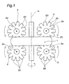
- Fig. 1 shows a simplified structural view which is an embodiment of the compressor of the invention.
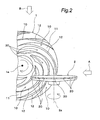
- Fig. 2 shows a partial enlarged view of the compressor.
- the compressor includes: a disc-shaped screw rotor 1 which rotates about a center axis 1a and which has, in its end face in a direction along the center axis 1a, a plurality of spirally extending groove portions 10 radially outward from the center axis 1a; and a disc-shaped gate rotor 2 which rotates about a center axis 2a and which has a plurality of tooth portions 20 arrayed circumferentially on its outer circumference, the groove portions 10 of the screw rotor 1 and the tooth portions 20 of the gate rotor 2 being engaged with each other to form a compression chamber 30.
- this compressor is a so-called PP-type single screw compressor.
- the term 'PP-type' means that the screw rotor 1 is formed into a plate-like shape while the gate rotor 2 is formed into a plate-like shape.
- This compressor is to be used in, for example, air conditioners, refrigerators and the like.
- the groove portions 10 are formed in each of two end faces of the screw rotor 1.
- the gate rotor 2 is provided two in number on each end face of the screw rotor 1. Then, as the screw rotor 1 rotates about the screw rotor center axis 1a along a direction indicated by an arrow, each gate rotor 2 subordinately rotates about the gate rotor center axis 2a along an arrow direction by mutual engagement of the groove portions 10 and the tooth portions 20.
- a plurality of thread ridges 12 spirally extending radially outward from the screw rotor center axis 1a, where the groove portions 10 are formed between neighboring ones of the thread ridges 12, 12.
- a casing (not shown) which has grooves that allow the gate rotors 2 to rotate.
- a space closed by the groove portion 10, the tooth portion 20 and the casing serves as the compression chamber 30.
- a suction port (not shown) communicating with the groove portions 10 on the outer peripheral side of the screw rotor 1.
- a discharge port (not shown) communicating with the groove portions 10 on the center side of the screw rotor 1.
- a fluid such as refrigerant gas introduced to the groove portion 10 through the suction port is compressed in the compression chamber 30 as the capacity of the compression chamber 30 is reduced by rotation of the screw rotor 1 and the gate rotor 2. Then, the compressed fluid is discharged through the discharge port.
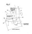
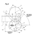
- a first plane S1 containing the screw rotor center axis 1a there are defined a first plane S1 containing the screw rotor center axis 1a, a second plane S2 orthogonally intersecting with the screw rotor center axis 1a, and a third plane S3 orthogonally intersecting with the two planes of the first plane S1 and the second plane S2.
- the second plane S2 is coincident with the axial end face of the screw rotor 1.
- Fig. 3 is a view taken along an arrow A direction of Fig. 2
- Fig. 4 is a view taken along an arrow B direction of Fig. 2 .
- the gate rotor center axis 2a is on the third plane S3. None of the tooth portions 20 of the gate rotor 2 overlaps with the first plane S1 as viewed in a direction orthogonal to the third plane S3.
- a distance d from an intersection point between a gate rotor plane SG formed by an first plane S1 side end face of every tooth portion 20 of the gate rotor 2 and the gate rotor center axis 2a to the first plane S1 (hereinafter, referred to as positional-shift distance d) is 0.05 to 0.4 time as large as an outer diameter D of the tooth portion 20 of the gate rotor 2 (0.05D ⁇ d ⁇ 0.4D).
- the gate rotor center axis 2a is inclined against the second plane S2 so that a tooth portion 20 of the gate rotor 2 closer to the screw rotor 1 becomes closer to the screw rotor center axis 1a than a tooth portion 20 of the gate rotor 2 farther from the screw rotor 1.
- An inclination angle ⁇ of the gate rotor center axis 2a is 5° - 30°.
- an engagement depth of the tooth portions 20 with the groove portions 10 is 0.2 time as large as an outer diameter D of the gate rotor 2.
- axis-to-axis distance L a distance L between the gate rotor center axis 2a and the screw rotor center axis 1a (hereinafter, referred to as axis-to-axis distance L) is 0.7 to 1.2 time as large as the outer diameter D of the gate rotor 2 (0.7D ⁇ L ⁇ 1.2D).
- an angle that a center line of the tooth portion 20 engaged with the groove portion 10 forms against a reference line parallel to the axial end face (second plane S2) of the screw rotor 1 is referred to as a gate rotor engagement angle ⁇ , and the angle of the center line (an intermediate line between leading side and unleading side) of the tooth portion 20 is measured from the reference line on a side of engagement starting.
- Fig. 5 shows, in a tooth portion 20 of the gate rotor 2, a minimum diameter, an intermediate diameter and a maximum diameter of engagement of the gate rotor 2, the engagement being done with the groove portions 10 of the screw rotor 1. Also in the tooth portion 20, a side face on the downstream side of the rotational direction of the gate rotor 2 is assumed as a leading-side side face 20a while a side face on the upstream side of the rotational direction of the gate rotor 2 is assumed as an unleading-side side face 20b.
- Figs. 6 to 9 show relationships between the gate rotor engagement angle ⁇ (see Fig. 4 ) and the screw rotor groove inclination angle ⁇ when the positional-shift distance d of the gate rotor center axis 2a (see Fig. 3 ) is changed as 0D, 0.1D, 0.2D and 0.3D with the inclination angle ⁇ of the gate rotor center axis 2a (see Fig. 3 ) set at 12°
- the figures are plotted engagement maximum diameters and intermediate diameters (see Fig. 5 ) of the gate rotor 2 with respect to the leading-side side face 20a and the unleading-side side face 20b (see Fig. 5 ), respectively.
- the number of groove portions 10 of the screw rotor 1 is three, and the number of tooth portions 20 of the gate rotor 2 is twelve.
- the screw rotor groove inclination angle ⁇ refers to an angle ⁇ formed by the side face 11 of a groove portion 10 of the screw rotor 1 against a plane St which orthogonally intersects with the rotational direction (indicated by an arrow RG) of the gate rotor 2 (i.e. a circumferential direction of the gate rotor 2) at a contact portion of the side face 11 of the groove portion 10 and the tooth portion 20 of the gate rotor 2.
- the screw rotor groove inclination angle ⁇ is expressed in positive values (+ direction) on the gate rotor rotational direction (arrow RG direction) side, and in negative values (- direction) on the side opposite to the gate rotor rotational direction (arrow RG direction).
- Fig. 6 shows a chart when the positional-shift distance d is 0D, where variation widths of the screw rotor groove inclination angle ⁇ become larger with respect to engagement maximum diameters and intermediate diameters of the gate rotor 2 in the leading-side side face 20a and the unleading-side side face 20b, respectively.
- Fig. 7 shows a chart when the positional-shift distance d is 0.1D, where variation widths of the screw rotor groove inclination angle ⁇ are smaller than those of the screw rotor groove inclination angle ⁇ shown in Fig. 6 .
- Fig. 8 shows a chart when the positional-shift distance d is 0.2D, where variation widths of the screw rotor groove inclination angle ⁇ are smaller than those of the screw rotor groove inclination angle ⁇ shown in Fig. 7 .
- Fig. 9 shows a chart when the positional-shift distance d is 0.3D, where variation widths of the screw rotor groove inclination angle ⁇ are smaller than those of the screw rotor groove inclination angle ⁇ shown in Fig. 6 .
- Figs. 10 to 13 show relationships between the gate rotor engagement angle ⁇ and the screw rotor groove inclination angle ⁇ when the inclination angle ⁇ of the gate rotor center axis 2a is changed as 0°, 5°, 12° and 20° with the positional-shift distance d set at 0D.
- the rest of the conditions are similar to those of Figs. 6 to 9 .
- Fig. 10 shows a chart when the inclination angle ⁇ of the gate rotor center axis 2a is 0°
- Fig. 11 shows a chart when the inclination angle ⁇ of the gate rotor center axis 2a is 5°
- Fig. 12 shows a chart when the inclination angle ⁇ of the gate rotor center axis 2a is 12°
- Fig. 13 shows a chart when the inclination angle ⁇ of the gate rotor center axis 2a is 20°, where the variation width of the screw rotor groove inclination angle ⁇ becomes smaller as the inclination angle ⁇ of the gate rotor center axis 2a becomes larger.
- Figs. 14 to 19 show relationships between the gate rotor engagement angle ⁇ and the screw rotor groove inclination angle ⁇ when the positional-shift distance d is changed as 0D, 0.05D, 0.1D, 0.15D, 0.2D and 0.3D with the inclination angle ⁇ of the gate rotor center axis 2a set at 0°.
- the rest of the conditions are similar to those of Figs. 6 to 9 .
- Fig. 14 shows a chart when the positional-shift distance d is 0D
- Fig. 15 shows a chart when the positional-shift distance d is 0.05D
- Fig. 16 shows a chart when the positional-shift distance d is 0.1D
- Fig. 17 shows a chart when the positional-shift distance d is 0.15D
- Fig. 18 shows a chart when the positional-shift distance d is 0.2D
- Fig. 19 shows a chart when the positional-shift distance d is 0.3D, where the variation width of the screw rotor groove inclination angle ⁇ is smaller when the positional-shift distance d is larger than 0D.
- seal portions 21a, 21b of the tooth portions 20 of the gate rotor 2 to be in contact with the groove portions 10 of the screw rotor 1 are formed into a curved-surface shape.
- a leading-side seal portion 21a is formed at the leading-side side face 20a of the tooth portion 20, while an unleading-side seal portion 21b is formed at the unleading-side side face 20b of the tooth portion 20.
- the screw rotor 1 moves along a downward-pointed arrow RS direction, while the gate rotor 2 moves along a leftward-pointed arrow RG direction.
- blow holes (leak clearances) 40, 50 shown by hatching are present.
- a leading-side blow hole 40 (shown by hatching) is present on an upstream side (compression chamber 30 side shown by hatching) of the leading-side seal portion 21a in the moving direction of the screw rotor 1
- an unleading-side blow hole 50 (shown by hatching) is present on an upstream side (the compression chamber 30 side) of the unleading-side seal portion 21b in the moving direction of the screw rotor 1.
- the fluid compressed in the compression chamber 30 passes through the blow holes 40, 50 to leak outside the casing 3 (shown by imaginary line).
- a degree of leakage effect of the leading-side blow hole 40 see Fig. 20
- a degree of leakage effect of the unleading-side blow hole 50 see Fig. 20
- a total degree of leakage effect of the leading-side blow hole 40 and the unleading-side blow hole 50 are shown.
- degree of leakage effect refers to a degree obtained by converting areas of the leading-side blow hole 40 and the unleading-side blow hole 50 into corresponding leak amounts, respectively, wherein a degree of 100 corresponds to a leak amounts when the positional-shift distance d is 0D (as in the conventional case).
- Fig. 21 shows degrees of leakage effect when the number of groove portions 10 of the screw rotor 1 is three and the number of tooth portions 20 of the gate rotor 2 is twelve. As the positional-shift distance d becomes larger, the degree of leakage effect becomes smaller, so that the compression efficiency is improved.
- Fig. 22 shows degrees of leakage effect when the number of groove portions 10 of the screw rotor 1 is six and the number of tooth portions 20 of the gate rotor 2 is twelve. As the positional-shift distance d becomes larger, the degree of leakage effect becomes smaller, so that the compression efficiency is improved.
- the changing width of the screw rotor groove inclination angle ⁇ during the course from suction to discharge becomes 16.0° at the leading-side side face 20a and 15.6° at the unleading-side side face 20b.
- the variation width of the inclination angle of the side faces 11 of the groove portion 10 of the screw rotor 1 to be in contact with the tooth portion 20 of the gate rotor 2, the inclination being against the circumferential direction of the gate rotor 2 and the variation width measuring from a radially outer side of the screw rotor 1 to its inner side, is made smaller, as compared with the variation width resulting when all the tooth portions of the gate rotor 2 overlap with the first plane S1 containing the screw rotor center axis 1a.
- the term, “circumferential direction of the gate rotor 2,” can be reworded as the rotational direction of the tooth portion 20 of the gate rotor 2 to be in contact with the side faces 11 of the groove portion 10 of the screw rotor 1.
- the term, “variation width of the screw rotor 1 from a radially outer side of the screw rotor 1 to its inner side,” refers to a variation width of the inclination angles of all the groove portions 10 from radially outer side to inner side of the screw rotor 1 to be concurrently in contact with the tooth portions 20 of the gate rotor 2.
- edge angles ⁇ 1, ⁇ 2 (see Fig. 20 ) of the seal portions of the gate rotor 2 to be engaged with the side faces of the groove portions 10 of the screw rotor 1 can be made obtuse, so that the blow holes (leak clearances) present at engagement portions between the groove portions 10 of the screw rotor 1 and the tooth portions 20 of the gate rotor 2 can be made smaller.
- the compression efficiency can be improved.
- wear of the seal portions of the gate rotor 2 can be reduced, allowing an improvement in durability to be achieved.
- the positional-shift distance d is 0.05 to 0.4 time as large as the outer diameter D of the tooth portion 20 of the gate rotor as viewed in the direction orthogonal to the third plane S3, the variation width of the screw rotor groove inclination angle ⁇ can be made even smaller.
- the gate rotor center axis 2a is inclined by 5° to 30° against the second plane S2 so that a tooth portion 20 of the gate rotor 2 closer to the screw rotor 1 becomes closer to the screw rotor center axis 1a than a tooth portion 20 of the gate rotor 2 farther from the screw rotor 1. Therefore, the variation width of the screw rotor groove inclination angle ⁇ can be made even smaller.
- the velocity of the screw rotor 1 engaged with the gate rotor 2 has large differences between outer peripheral portions and central portion.
- the rotational speed of the gate rotor 2 becomes larger relative to the rotational speed of the screw rotor 1, so that the screw rotor groove inclination angle ⁇ is varied to a large extent.
- the variation width of the screw rotor groove inclination angle ⁇ can be made smaller without increasing the outer diameter of the screw rotor 1.
- the distance L between the gate rotor center axis 2a and the screw rotor center axis 1a is 0.7 to 1.2 times as large as the outer diameter D of the gate rotor 2. Therefore, the distance L can be made smaller, allowing a downsizing to be achieved.
- the changing width of the screw rotor groove inclination angle ⁇ can be made small, the variation width of the contact angle between the gate rotor 2 and the screw rotor 1 can be suppressed even if the distance L is reduced.
- the downsizing can be achieved while the compression efficiency is maintained.
- seal portions 21a, 21b of the tooth portions 20 of the gate rotor 2 to be in contact with the groove portions 10 of the screw rotor 1 are formed into a curved-surface shape, leaks of the compressed fluid from engagement portions between the tooth portions 20 of the gate rotor 2 and the groove portions 10 of the screw rotor 1 can be reduced, so that the compression efficiency can be improved.
- the seal portions 21a, 21b of the gate rotor 2 can be formed into a curved-surface shape. More specifically, without increasing the thickness of the gate rotor 2, maximum and minimum values of the inclination angle of the seal portions 21a, 21b can be fulfilled by machining the groove portions 10 of the screw rotor 1 with an end mill and by forming the seal portions 21a, 21b of the tooth portions 20 of the gate rotor 2 into a curved-surface shape with an end mill.
- the groove portion 10 may be provided only in one of the end faces of the screw rotor 1.
- the number of the gate rotors 2 may be freely increased or decreased.
- the seal portions 21a, 21b of the tooth portions 20 of the gate rotor 2 to be in contact with the groove portions 10 of the screw rotor 1 may also be formed into an acute-angle shape.
- the screw rotor 1 and the gate rotor 2 may be rotated in opposite directions.
Landscapes
- Engineering & Computer Science (AREA)
- Mechanical Engineering (AREA)
- General Engineering & Computer Science (AREA)
- Applications Or Details Of Rotary Compressors (AREA)
Abstract
Description
- The present invention relates to a compressor to be used in, for example, air conditioners, refrigerators and the like.
- Conventionally, there has been provided a compressor including a disc-shaped screw rotor which rotates about a center axis and which has, in its end face in a center-axis direction, a plurality of spirally extending groove portions radially outward from the center axis, and a gate rotor which rotates about a center axis and which has a plurality of tooth portions arrayed circumferentially on its outer circumference, the groove portions of the screw rotor and the tooth portions of the gate rotor being engaged with each other to form a compression chamber (see
JP 60-10161 B - That is, this compressor is a so-called PP type single screw compressor. The term "PP type" means that the screw rotor is formed into a plate-like shape and moreover the gate rotor is formed into a plate-like shape.
- Then, as viewed in a direction orthogonal to the screw rotor center axis and the gate rotor center axis, all the tooth portions of the gate rotor overlap with the screw rotor center axis. That is, the tooth portions of the gate rotor are engaged with the groove portions of the screw rotor along the radial direction of the screw rotor.
- With a view to preventing interferences between the screw rotor and the gate rotor, side faces of the gate rotor tooth portions are given a maximum angle and a minimum angle each of which is formed by a gate rotor tooth-portion side face and a screw rotor groove wall surface on a plane which orthogonally intersects with the gate rotor plane and which contains a rotational direction of a tooth center line extending radial direction of the gate rotor (hereinafter, angles formed between the maximum angle and the minimum angle will be referred to as edge angles of the gate rotor; see edge angles δ1, δ2 of
Fig. 20 ). - However, with the conventional compressor described above, since all the tooth portions of the gate rotor are aligned with the screw rotor center axis as viewed in a direction orthogonal to the screw rotor center axis and the gate rotor center axis, angles formed by side faces of the screw rotor groove against side faces of the gate rotor tooth portions on the plane orthogonally intersecting with the gate rotor plane and containing the rotational direction of the gate rotor tooth center line involves a larger difference between a maximum value and a minimum value.
- As a result of this, edge angles of gate rotor seal portions to be engaged with the side faces of the screw rotor groove portion become acute, so that a blow hole (leak clearance) present at an engagement portion between the screw rotor groove portion and the gate rotor tooth portion becomes larger. This would result in a lowered compression efficiency.
- Accordingly, an object of the present invention is to provide a compressor in which the blow hole is made smaller so as to improve the compression efficiency.
- In order to achieve the above object, there is provided a compressor comprising: a disc-shaped screw rotor which rotates about a center axis and which has, in at least one end face thereof in a direction along the center axis, a plurality of spirally extending groove portions radially outward from the center axis; and a gate rotor which rotates about a center axis and which has a plurality of tooth portions arrayed circumferentially on its outer circumference, the groove portions of the screw rotor and the tooth portions of the gate rotor being engaged with each other to form a compression chamber, wherein
a variation width of an inclination angle to which a side face of a groove portion of the screw rotor to be in contact with the tooth portions of the gate rotor is inclined against a circumferential direction of the gate rotor, the variation being over a range from radially outer side to inner side of the screw rotor,
is made smaller than
a variation width resulting when all the tooth portions of the gate rotor overlap with a plane containing the screw rotor center axis. - According to the compressor of this invention, the variation width of the inclination angle to which the side face of the groove portion of the screw rotor to be in contact with the tooth portions of the gate rotor is inclined against the circumferential direction of the gate rotor, the variation being over a range from radially outer side to inner side of the screw rotor; is made smaller than a variation width resulting when all the tooth portions of the gate rotor overlap with a plane containing the screw rotor center axis. Therefore, edge angles of the seal portions of the gate rotor to be engaged with side faces of the groove portion of the screw rotor can be made obtuse, so that the blow holes (leak clearances) present at engagement portions between the groove portion of the screw rotor and the tooth portions of the gate rotor can be made smaller, allowing the compression efficiency to be improved. Besides, wear of the seal portions of the gate rotor can be reduced, allowing an improvement in durability to be achieved.
- Also, there is provided a compressor comprising: a disc-shaped screw rotor which rotates about a center axis and which has, in at least one end face thereof in a direction along the center axis, a plurality of spirally extending groove portions (10) radially outward from the center axis; and a gate rotor which rotates about a center axis and which has a plurality of tooth portions arrayed circumferentially on its outer circumference, the groove portions of the screw rotor and the tooth portions of the gate rotor being engaged with each other to form a compression chamber, wherein
with respect to a first plane containing the screw rotor center axis, a second plane which intersects orthogonally with the screw rotor center axis, and a third plane which intersects orthogonally with the first plane (S1) and the second plane,
the gate rotor center axis is on the third plane, and
at least one of all the tooth portions of the gate rotor does not overlap with the first plane as viewed in a direction orthogonal to the third plane. - According to the compressor of this invention, the gate rotor center axis is on the third plane, and at least one of all the tooth portions of the gate rotor does not overlap with the first plane as viewed in a direction orthogonal to the third plane. Therefore, the side face of the groove portion of the screw rotor to be in contact with the tooth portions of the gate rotor can be set at approximately 90° against the rotational direction of the gate rotor (i.e. circumferential direction of the gate rotor) in its portion to be in contact with the side face of the groove portion of the screw rotor. Thus, the variation width of an angle formed by the side face of the groove portion of the screw rotor (hereinafter, referred to as screw rotor groove inclination angle) against a plane orthogonally intersecting with the rotational direction of the gate rotor (the circumferential direction of the gate rotor) can be made smaller.
- Therefore, edge angles of the seal portions of the gate rotor to be engaged with side faces of the groove portion of the screw rotor can be made obtuse, so that the blow holes (leak clearances) present at engagement portions between the groove portion of the screw rotor and the tooth portions of the gate rotor can be made smaller, allowing the compression efficiency to be improved. Besides, wear of the seal portions of the gate rotor can be reduced, allowing an improvement in durability to be achieved.
- In one embodiment of the invention, as viewed in the direction orthogonal to the third plane, a distance from an intersection point between a gate rotor plane formed by the first plane side end face of every tooth portion of the gate rotor and the gate rotor center axis (2a) to the first plane is 0.05 to 0.4 time as large as an outer diameter of the tooth portion of the gate rotor.
- According to the compressor of this embodiment, as viewed in the direction orthogonal to the third plane, a distance from an intersection point between a gate rotor plane formed by the first plane side end face of every tooth portion of the gate rotor and the gate rotor center axis to the first plane is 0.05 to 0.4 time as large as an outer diameter of the tooth portion of the gate rotor. Therefore, the variation width of the screw rotor groove inclination angle can be made even smaller.
- In one embodiment of the invention, as viewed in the direction orthogonal to the third plane, the gate rotor center axis is inclined by 5° to 30° against the second plane so that a tooth portion of the gate rotor closer to the screw rotor becomes closer to the screw rotor center axis than a tooth portion of the gate rotor farther from the screw rotor.
- According to the compressor of this embodiment, as viewed in the direction orthogonal to the third plane, the gate rotor center axis is inclined by 5° to 30° against the second plane so that a tooth portion of the gate rotor closer to the screw rotor becomes closer to the screw rotor center axis than a tooth portion of the gate rotor farther from the screw rotor. Therefore, the variation width of the screw rotor groove inclination angle can be made even smaller.
- In one embodiment of the invention, as viewed in a direction orthogonal to the first plane, a distance between the gate rotor center axis and the screw rotor center axis is 0.7 to 1.2 times as large as an outer diameter of the gate rotor.
- According to the compressor of this embodiment, as viewed in a direction orthogonal to the first plane, a distance L between the gate rotor center axis and the screw rotor center axis is 0.7 to 1.2 times as large as an outer diameter D of the gate rotor. Therefore, the distance L can be made smaller, allowing a downsizing to be achieved.
- In one embodiment of the invention, seal portions of the tooth portions of the gate rotor to be in contact with the groove portions of the screw rotor are formed into a curved-surface shape.
- According to the compressor of this embodiment, since the seal portions of the tooth portions of the gate rotor to be in contact with the groove portion of the screw rotor are formed into a curved-surface shape, leakage of the compressed fluid from engagement portions between the tooth portions of the gate rotor and the groove portion of the screw rotor can be reduced, so that the compression efficiency can be improved.
- According to the compressor of the invention, the variation width of the inclination angle to which the side face of the groove portion of the screw rotor to be in contact with the tooth portions of the gate rotor is inclined against the circumferential direction of the gate rotor, the variation being over a range from radially outer side to inner side of the screw rotor, is made smaller than a variation width resulting when all the tooth portions of the gate rotor overlap with a plane containing the screw rotor center axis. Therefore, the blow holes can be made smaller, allowing the compression efficiency to be improved.
- Also, according to the compressor of the invention, the gate rotor center axis is on the third plane, and at least one of all the tooth portions of the gate rotor does not overlap with the first plane as viewed in a direction orthogonal to the third plane. Therefore, the blow holes can be made smaller, allowing the compression efficiency to be improved.
-
-
Fig. 1 is a simplified structural view showing an embodiment of the compressor of the invention; -
Fig. 2 is a partial enlarged view of the compressor; -
Fig. 3 is a simplified side view of the compressor; -
Fig. 4 is a simplified plan view of the compressor; -
Fig. 5 is a enlarged plan view of the compressor; -
Fig. 6 is a graph showing a relationship between a gate rotor engagement angle γ and a screw rotor groove inclination angle β under the condition that a gate-rotor center axis inclination angle α is 12° and a positional-shift distance d is 0D; -
Fig. 7 is a graph showing a relationship between a gate rotor engagement angle γ and a screw rotor groove inclination angle β under the condition that a gate-rotor center axis inclination angle α is 12° and a positional-shift distance d is 0.1D; -
Fig. 8 is a graph showing a relationship between a gate rotor engagement angle γ and a screw rotor groove inclination angle β under the condition that a gate-rotor center axis inclination angle α is 12° and a positional-shift distance d is 0.2D; -
Fig. 9 is a graph showing a relationship between a gate rotor engagement angle γ and a screw rotor groove inclination angle β under the condition that a gate-rotor center axis inclination angle α is 12° and a positional-shift distance d is 0.3D; -
Fig. 10 is a graph showing a relationship between a gate rotor engagement angle γ and a screw rotor groove inclination angle β under the condition that a gate-rotor center axis inclination angle α is 0° and a positional-shift distance d is 0D; -
Fig. 11 is a graph showing a relationship between a gate rotor engagement angle γ and a screw rotor groove inclination angle β under the condition that a gate-rotor center axis inclination angle α is 5° and a positional-shift distance d is 0D; -
Fig. 12 is a graph showing a relationship between a gate rotor engagement angle γ and a screw rotor groove inclination angle β under the condition that a gate-rotor center axis inclination angle α is 12° and a positional-shift distance d is 0D; -
Fig. 13 is a graph showing a relationship between a gate rotor engagement angle γ and a screw rotor groove inclination angle β under the condition that a gate-rotor center axis inclination angle α is 20° and a positional-shift distance d is 0D; -
Fig. 14 is a graph showing a relationship between a gate rotor engagement angle γ and a screw rotor groove inclination angle β under the condition that a gate-rotor center axis inclination angle α is 0° and a positional-shift distance d is 0D; -
Fig. 15 is a graph showing a relationship between a gate rotor engagement angle γ and a screw rotor groove inclination angle β under the condition that a gate-rotor center axis inclination angle α is 0° and a positional-shift distance d is 0.05D; -
Fig. 16 is a graph showing a relationship between a gate rotor engagement angle γ and a screw rotor groove inclination angle β under the condition that a gate-rotor center axis inclination angle α is 0° and a positional-shift distance d is 0.1D; -
Fig. 17 is a graph showing a relationship between a gate rotor engagement angle γ and a screw rotor groove inclination angle β under the condition that a gate-rotor center axis inclination angle α is 0° and a positional-shift distance d is 0.15D; -
Fig. 18 is a graph showing a relationship between a gate rotor engagement angle γ and a screw rotor groove inclination angle β under the condition that a gate-rotor center axis inclination angle α is 0° and a positional-shift distance d is 0.2D; -
Fig. 19 is a graph showing a relationship between a gate rotor engagement angle γ and a screw rotor groove inclination angle β under the condition that a gate-rotor center axis inclination angle α is 0° and a positional-shift distance d is 0.3D; -
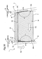
Fig. 20 is an enlarged sectional view of the compressor; -
Fig. 21 is a graph showing a relationship between the positional-shift distance d and the degree of leakage effect with three screw rotor groove portions and twelve gate rotor tooth portions provided; -
Fig. 22 is a graph showing a relationship between the positional-shift distance d and the degree of leakage effect with six screw rotor groove portions and twelve gate rotor tooth portions provided; - Hereinbelow, the present invention will be described in detail by way of embodiment thereof illustrated in the accompanying drawings.
-
Fig. 1 shows a simplified structural view which is an embodiment of the compressor of the invention.Fig. 2 shows a partial enlarged view of the compressor. As shown inFigs. 1 and2 , the compressor includes: a disc-shapedscrew rotor 1 which rotates about acenter axis 1a and which has, in its end face in a direction along thecenter axis 1a, a plurality of spirally extendinggroove portions 10 radially outward from thecenter axis 1a; and a disc-shapedgate rotor 2 which rotates about acenter axis 2a and which has a plurality oftooth portions 20 arrayed circumferentially on its outer circumference, thegroove portions 10 of thescrew rotor 1 and thetooth portions 20 of thegate rotor 2 being engaged with each other to form acompression chamber 30. - That is, this compressor is a so-called PP-type single screw compressor. The term 'PP-type' means that the
screw rotor 1 is formed into a plate-like shape while thegate rotor 2 is formed into a plate-like shape. This compressor is to be used in, for example, air conditioners, refrigerators and the like. - The
groove portions 10 are formed in each of two end faces of thescrew rotor 1. Thegate rotor 2 is provided two in number on each end face of thescrew rotor 1. Then, as thescrew rotor 1 rotates about the screwrotor center axis 1a along a direction indicated by an arrow, eachgate rotor 2 subordinately rotates about the gaterotor center axis 2a along an arrow direction by mutual engagement of thegroove portions 10 and thetooth portions 20. - On an end face of the
screw rotor 1 are provided a plurality ofthread ridges 12 spirally extending radially outward from the screwrotor center axis 1a, where thegroove portions 10 are formed between neighboring ones of thethread ridges tooth portions 20 engaged with one of thegroove portions 10, side faces (i.e. seal portions) of thetooth portion 20 come into contact with side faces 11 of thegroove portion 10 to seal thecompression chamber 30, while thetooth portion 20 is rotated by the side faces 11 of thegroove portion 10. - On an end face of the
screw rotor 1 is attached a casing (not shown) which has grooves that allow thegate rotors 2 to rotate. A space closed by thegroove portion 10, thetooth portion 20 and the casing serves as thecompression chamber 30. - In the casing is provided a suction port (not shown) communicating with the
groove portions 10 on the outer peripheral side of thescrew rotor 1. In the casing is also provided a discharge port (not shown) communicating with thegroove portions 10 on the center side of thescrew rotor 1. - Referring to action of the compressor, a fluid such as refrigerant gas introduced to the
groove portion 10 through the suction port is compressed in thecompression chamber 30 as the capacity of thecompression chamber 30 is reduced by rotation of thescrew rotor 1 and thegate rotor 2. Then, the compressed fluid is discharged through the discharge port. - As shown in the simplified front view of
Fig. 3 and the simplified plan view ofFig. 4 , there are defined a first plane S1 containing the screwrotor center axis 1a, a second plane S2 orthogonally intersecting with the screwrotor center axis 1a, and a third plane S3 orthogonally intersecting with the two planes of the first plane S1 and the second plane S2. The second plane S2 is coincident with the axial end face of thescrew rotor 1.Fig. 3 is a view taken along an arrow A direction ofFig. 2 , andFig. 4 is a view taken along an arrow B direction ofFig. 2 . - The gate
rotor center axis 2a is on the third plane S3. None of thetooth portions 20 of thegate rotor 2 overlaps with the first plane S1 as viewed in a direction orthogonal to the third plane S3. - As viewed in the direction orthogonal to the third plane S3, a distance d from an intersection point between a gate rotor plane SG formed by an first plane S1 side end face of every
tooth portion 20 of thegate rotor 2 and the gaterotor center axis 2a to the first plane S1 (hereinafter, referred to as positional-shift distance d) is 0.05 to 0.4 time as large as an outer diameter D of thetooth portion 20 of the gate rotor 2 (0.05D ≤ d ≤ 0.4D). - As viewed in the direction orthogonal to the third plane S3, the gate
rotor center axis 2a is inclined against the second plane S2 so that atooth portion 20 of thegate rotor 2 closer to thescrew rotor 1 becomes closer to the screwrotor center axis 1a than atooth portion 20 of thegate rotor 2 farther from thescrew rotor 1. An inclination angle α of the gaterotor center axis 2a is 5° - 30°. In this case, an engagement depth of thetooth portions 20 with thegroove portions 10 is 0.2 time as large as an outer diameter D of thegate rotor 2. - As viewed in a direction orthogonal to the first plane S1, a distance L between the gate
rotor center axis 2a and the screwrotor center axis 1a (hereinafter, referred to as axis-to-axis distance L) is 0.7 to 1.2 time as large as the outer diameter D of the gate rotor 2 (0.7D ≤ L ≤ 1.2D). - In the gate rotor plane SG, an angle that a center line of the
tooth portion 20 engaged with thegroove portion 10 forms against a reference line parallel to the axial end face (second plane S2) of thescrew rotor 1 is referred to as a gate rotor engagement angle γ, and the angle of the center line (an intermediate line between leading side and unleading side) of thetooth portion 20 is measured from the reference line on a side of engagement starting. - The enlarged plan view of
Fig. 5 shows, in atooth portion 20 of thegate rotor 2, a minimum diameter, an intermediate diameter and a maximum diameter of engagement of thegate rotor 2, the engagement being done with thegroove portions 10 of thescrew rotor 1. Also in thetooth portion 20, a side face on the downstream side of the rotational direction of thegate rotor 2 is assumed as a leading-side side face 20a while a side face on the upstream side of the rotational direction of thegate rotor 2 is assumed as an unleading-side side face 20b. - Next,
Figs. 6 to 9 show relationships between the gate rotor engagement angle γ (seeFig. 4 ) and the screw rotor groove inclination angle β when the positional-shift distance d of the gaterotor center axis 2a (seeFig. 3 ) is changed as 0D, 0.1D, 0.2D and 0.3D with the inclination angle α of the gaterotor center axis 2a (seeFig. 3 ) set at 12° In the figures are plotted engagement maximum diameters and intermediate diameters (seeFig. 5 ) of thegate rotor 2 with respect to the leading-side side face 20a and the unleading-side side face 20b (seeFig. 5 ), respectively. The number ofgroove portions 10 of thescrew rotor 1 is three, and the number oftooth portions 20 of thegate rotor 2 is twelve. - It is to be noted here that the screw rotor groove inclination angle β, as shown in
Fig. 20 , refers to an angle β formed by theside face 11 of agroove portion 10 of thescrew rotor 1 against a plane St which orthogonally intersects with the rotational direction (indicated by an arrow RG) of the gate rotor 2 (i.e. a circumferential direction of the gate rotor 2) at a contact portion of theside face 11 of thegroove portion 10 and thetooth portion 20 of thegate rotor 2. In addition, with the plane St taken as a reference, the screw rotor groove inclination angle β is expressed in positive values (+ direction) on the gate rotor rotational direction (arrow RG direction) side, and in negative values (- direction) on the side opposite to the gate rotor rotational direction (arrow RG direction). -
Fig. 6 shows a chart when the positional-shift distance d is 0D, where variation widths of the screw rotor groove inclination angle β become larger with respect to engagement maximum diameters and intermediate diameters of thegate rotor 2 in the leading-side side face 20a and the unleading-side side face 20b, respectively. -
Fig. 7 shows a chart when the positional-shift distance d is 0.1D, where variation widths of the screw rotor groove inclination angle β are smaller than those of the screw rotor groove inclination angle β shown inFig. 6 . -
Fig. 8 shows a chart when the positional-shift distance d is 0.2D, where variation widths of the screw rotor groove inclination angle β are smaller than those of the screw rotor groove inclination angle β shown inFig. 7 . -
Fig. 9 shows a chart when the positional-shift distance d is 0.3D, where variation widths of the screw rotor groove inclination angle β are smaller than those of the screw rotor groove inclination angle β shown inFig. 6 . - Also,
Figs. 10 to 13 show relationships between the gate rotor engagement angle γ and the screw rotor groove inclination angle γ when the inclination angle α of the gaterotor center axis 2a is changed as 0°, 5°, 12° and 20° with the positional-shift distance d set at 0D. The rest of the conditions are similar to those ofFigs. 6 to 9 . -
Fig. 10 shows a chart when the inclination angle α of the gaterotor center axis 2a is 0°,Fig. 11 shows a chart when the inclination angle α of the gaterotor center axis 2a is 5°,Fig. 12 shows a chart when the inclination angle α of the gaterotor center axis 2a is 12°, andFig. 13 shows a chart when the inclination angle α of the gaterotor center axis 2a is 20°, where the variation width of the screw rotor groove inclination angle β becomes smaller as the inclination angle α of the gaterotor center axis 2a becomes larger. - That is, in
Figs. 11 to 13 , since at least one of all thetooth portions 20 of thegate rotor 2 does not overlap with the first plane S1, the variation width of the screw rotor groove inclination angle β can be made smaller as compared with the case where all thetooth portions 20 of thegate rotor 2 shown inFig. 10 overlap with the first plane S1. - Also,
Figs. 14 to 19 show relationships between the gate rotor engagement angle γ and the screw rotor groove inclination angle β when the positional-shift distance d is changed as 0D, 0.05D, 0.1D, 0.15D, 0.2D and 0.3D with the inclination angle α of the gaterotor center axis 2a set at 0°. The rest of the conditions are similar to those ofFigs. 6 to 9 . -
Fig. 14 shows a chart when the positional-shift distance d is 0D,Fig. 15 shows a chart when the positional-shift distance d is 0.05D,Fig. 16 shows a chart when the positional-shift distance d is 0.1D,Fig. 17 shows a chart when the positional-shift distance d is 0.15D,Fig. 18 shows a chart when the positional-shift distance d is 0.2D, andFig. 19 shows a chart when the positional-shift distance d is 0.3D, where the variation width of the screw rotor groove inclination angle β is smaller when the positional-shift distance d is larger than 0D. - That is, in
Figs. 15 to 19 , since none of thetooth portions 20 of thegate rotor 2 overlaps with the first plane S1, the variation width of the screw rotor groove inclination angle β can be made smaller as compared with the case where all thetooth portions 20 of thegate rotor 2 shown inFig. 14 overlap with the first plane S1. - As shown in the enlarged sectional view of
Fig. 20 ,seal portions tooth portions 20 of thegate rotor 2 to be in contact with thegroove portions 10 of thescrew rotor 1 are formed into a curved-surface shape. - That is, a leading-
side seal portion 21a is formed at the leading-side side face 20a of thetooth portion 20, while an unleading-side seal portion 21b is formed at the unleading-side side face 20b of thetooth portion 20. - The
screw rotor 1 moves along a downward-pointed arrow RS direction, while thegate rotor 2 moves along a leftward-pointed arrow RG direction. - At engagement portions between the
groove portion 10 of thescrew rotor 1 and thetooth portion 20 of thegate rotor 2, blow holes (leak clearances) 40, 50 shown by hatching are present. - More specifically, a leading-side blow hole 40 (shown by hatching) is present on an upstream side (
compression chamber 30 side shown by hatching) of the leading-side seal portion 21a in the moving direction of thescrew rotor 1, while an unleading-side blow hole 50 (shown by hatching) is present on an upstream side (thecompression chamber 30 side) of the unleading-side seal portion 21b in the moving direction of thescrew rotor 1. - The fluid compressed in the
compression chamber 30 passes through the blow holes 40, 50 to leak outside the casing 3 (shown by imaginary line). -
Figs. 21 and 22 show a relationship between the positional-shift distance d (seeFig. 3 ) and the degree of leakage effect. In this case, only the positional-shift distance d is changed within a range of 0D to 0.4D without any inclination of the gaterotor center axis 2a (α=0°). A degree of leakage effect of the leading-side blow hole 40 (seeFig. 20 ), a degree of leakage effect of the unleading-side blow hole 50 (seeFig. 20 ), and a total degree of leakage effect of the leading-side blow hole 40 and the unleading-side blow hole 50 are shown. It is noted here that the term, "degree of leakage effect," refers to a degree obtained by converting areas of the leading-side blow hole 40 and the unleading-side blow hole 50 into corresponding leak amounts, respectively, wherein a degree of 100 corresponds to a leak amounts when the positional-shift distance d is 0D (as in the conventional case). -
Fig. 21 shows degrees of leakage effect when the number ofgroove portions 10 of thescrew rotor 1 is three and the number oftooth portions 20 of thegate rotor 2 is twelve. As the positional-shift distance d becomes larger, the degree of leakage effect becomes smaller, so that the compression efficiency is improved. -
Fig. 22 shows degrees of leakage effect when the number ofgroove portions 10 of thescrew rotor 1 is six and the number oftooth portions 20 of thegate rotor 2 is twelve. As the positional-shift distance d becomes larger, the degree of leakage effect becomes smaller, so that the compression efficiency is improved. - According to the compressor of the above-described constitution, since the gate
rotor center axis 2a is present on the third plane S3 and since at least one of all thetooth portions 20 of thegate rotor 2 does not overlap with the first plane S1 as viewed in a direction orthogonal to the third plane S3, side faces 11 of agroove portion 10 of thescrew rotor 1 to be in contact with thetooth portion 20 of thegate rotor 2 can be set at approximately 90° against the rotational direction (indicated by arrow RG) of thetooth portion 20 of thegate rotor 2 to be in contact with the side faces 11 of thegroove portion 10 of the screw rotor 1 (i.e. against the circumferential direction of the gate rotor 2) as shown inFig. 20 . Thus, the variation width of the screw rotor groove inclination angle β can be reduced. - More specifically, in cases where the positional shift or inclination of the
gate rotor 2 as in the present invention is not used (prior art), the changing width of the screw rotor groove inclination angle β during the course from suction to discharge becomes 16.0° at the leading-side side face 20a and 15.6° at the unleading-side side face 20b. In contrast to this, in a case where the positional shift or inclination of thegate rotor 2 of the invention is applied to a compressor whose configuration (gate rotor tooth number, screw rotor groove number, gate rotor diameter, axis-to-axis distance, gate rotor tooth width, and suction cut angle) is similar to that of the prior art, the results are 6.5° at that the leading-side side face 20a and 13.8° at the unleading-side side face 20b. - In other words, the variation width of the inclination angle of the side faces 11 of the
groove portion 10 of thescrew rotor 1 to be in contact with thetooth portion 20 of thegate rotor 2, the inclination being against the circumferential direction of thegate rotor 2 and the variation width measuring from a radially outer side of thescrew rotor 1 to its inner side, is made smaller, as compared with the variation width resulting when all the tooth portions of thegate rotor 2 overlap with the first plane S1 containing the screwrotor center axis 1a. In addition, the term, "circumferential direction of thegate rotor 2," can be reworded as the rotational direction of thetooth portion 20 of thegate rotor 2 to be in contact with the side faces 11 of thegroove portion 10 of thescrew rotor 1. Also, the term, "variation width of thescrew rotor 1 from a radially outer side of thescrew rotor 1 to its inner side," refers to a variation width of the inclination angles of all thegroove portions 10 from radially outer side to inner side of thescrew rotor 1 to be concurrently in contact with thetooth portions 20 of thegate rotor 2. - Therefore, edge angles δ1, δ2 (see
Fig. 20 ) of the seal portions of thegate rotor 2 to be engaged with the side faces of thegroove portions 10 of thescrew rotor 1 can be made obtuse, so that the blow holes (leak clearances) present at engagement portions between thegroove portions 10 of thescrew rotor 1 and thetooth portions 20 of thegate rotor 2 can be made smaller. Thus, the compression efficiency can be improved. Besides, wear of the seal portions of thegate rotor 2 can be reduced, allowing an improvement in durability to be achieved. - In consequence, in the present invention, it has been found that in the PP-type single screw compressor, the angle of side faces of the
groove portions 10 of thescrew rotor 1 to be in contact with thetooth portions 20 of thegate rotor 2 is varied by shifting the position of thegate rotor 2 relative to thescrew rotor 1. - Also, since the positional-shift distance d is 0.05 to 0.4 time as large as the outer diameter D of the
tooth portion 20 of the gate rotor as viewed in the direction orthogonal to the third plane S3, the variation width of the screw rotor groove inclination angle β can be made even smaller. - Also, as viewed in the direction orthogonal to the third plane S3, the gate
rotor center axis 2a is inclined by 5° to 30° against the second plane S2 so that atooth portion 20 of thegate rotor 2 closer to thescrew rotor 1 becomes closer to the screwrotor center axis 1a than atooth portion 20 of thegate rotor 2 farther from thescrew rotor 1. Therefore, the variation width of the screw rotor groove inclination angle β can be made even smaller. - That is, in the PP-type single screw compressor, the velocity of the
screw rotor 1 engaged with thegate rotor 2 has large differences between outer peripheral portions and central portion. In particular, at the central portion of thescrew rotor 1, the rotational speed of thegate rotor 2 becomes larger relative to the rotational speed of thescrew rotor 1, so that the screw rotor groove inclination angle β is varied to a large extent. - As a solution to this, it can be conceived to increase the axis-to-axis distance L between the
screw rotor 1 and thegate rotor 2 so that velocity changes of thescrew rotor 1 between outer peripheral portions and central portion of thescrew rotor 1 becomes small. However, this incurs a problem that the outer diameter of thescrew rotor 1 is increased, leading to an increased maximum diameter of the compressor. - Accordingly, by making the gate
rotor center axis 2a inclined by 5° to 30° against a plane orthogonal to the screwrotor center axis 1a, the variation width of the screw rotor groove inclination angle β can be made smaller without increasing the outer diameter of thescrew rotor 1. - Also, as viewed in the direction orthogonal to the first plane S1, the distance L between the gate
rotor center axis 2a and the screwrotor center axis 1a is 0.7 to 1.2 times as large as the outer diameter D of thegate rotor 2. Therefore, the distance L can be made smaller, allowing a downsizing to be achieved. - In other words, since the changing width of the screw rotor groove inclination angle β can be made small, the variation width of the contact angle between the
gate rotor 2 and thescrew rotor 1 can be suppressed even if the distance L is reduced. Thus, the downsizing can be achieved while the compression efficiency is maintained. - Also, since the
seal portions tooth portions 20 of thegate rotor 2 to be in contact with thegroove portions 10 of thescrew rotor 1 are formed into a curved-surface shape, leaks of the compressed fluid from engagement portions between thetooth portions 20 of thegate rotor 2 and thegroove portions 10 of thescrew rotor 1 can be reduced, so that the compression efficiency can be improved. - In other words, since the variation width of the screw rotor groove inclination angle β can be made small, the
seal portions gate rotor 2 can be formed into a curved-surface shape.. More specifically, without increasing the thickness of thegate rotor 2, maximum and minimum values of the inclination angle of theseal portions groove portions 10 of thescrew rotor 1 with an end mill and by forming theseal portions tooth portions 20 of thegate rotor 2 into a curved-surface shape with an end mill. - The present invention is not limited to the above-described embodiment. For example, the
groove portion 10 may be provided only in one of the end faces of thescrew rotor 1. Also, the number of thegate rotors 2 may be freely increased or decreased. Further, theseal portions tooth portions 20 of thegate rotor 2 to be in contact with thegroove portions 10 of thescrew rotor 1 may also be formed into an acute-angle shape. Besides, thescrew rotor 1 and thegate rotor 2 may be rotated in opposite directions.
Claims (6)
- A compressor comprising: a disc-shaped screw rotor (1) which rotates about a center axis (1a) and which has, in at least one end face thereof in a direction along the center axis (1a), a plurality of spirally extending groove portions (10) radially outward from the center axis (1a); and a gate rotor (2) which rotates about a center axis (2a) and which has a plurality of tooth portions (20) arrayed circumferentially on its outer circumference, the groove portions (10) of the screw rotor (1) and the tooth portions (20) of the gate rotor (2) being engaged with each other to form a compression chamber (30), wherein
a variation width of an inclination angle to which a side face (11) of a groove portion (10) of the screw rotor (1) to be in contact with the tooth portions (20) of the gate rotor (2) is inclined against a circumferential direction of the gate rotor (2), the variation being over a range from radially outer side to inner side of the screw rotor (1),
is made smaller than
a variation width resulting when all the tooth portions (20) of the gate rotor (2) overlap with a plane (S1) containing the screw rotor center axis (1a). - A compressor comprising: a disc-shaped screw rotor (1) which rotates about a center axis (1a) and which has, in at least one end face thereof in a direction along the center axis (1a), a plurality of spirally extending groove portions (10) radially outward from the center axis (1a); and a gate rotor (2) which rotates about a center axis (2a) and which has a plurality of tooth portions (20) arrayed circumferentially on its outer circumference, the groove portions (10) of the screw rotor (1) and the tooth portions (20) of the gate rotor (2) being engaged with each other to form a compression chamber (30), wherein
with respect to a first plane (S1) containing the screw rotor center axis (1a), a second plane (S2) which intersects orthogonally with the screw rotor center axis (1a), and a third plane (S3) which intersects orthogonally with the first plane (S1) and the second plane (S2),
the gate rotor center axis (2a) is on the third plane (S3), and
at least one of all the tooth portions (20) of the gate rotor (2) does not overlap with the first plane (S1) as viewed in a direction orthogonal to the third plane (S3). - The compressor as claimed in Claim 2, wherein
as viewed in the direction orthogonal to the third plane (S3), a distance (d) from an intersection point (P) between a gate rotor plane (SG) formed by the first plane (S1) side end face of every tooth portion (20) of the gate rotor (2) and the gate rotor center axis (2a) to the first plane (S1) is 0.05 to 0.4 time as large as an outer diameter (D) of the tooth portion (20) of the gate rotor (2). - The compressor as claimed in Claim 2, wherein
as viewed in the direction orthogonal to the third plane (S3), the gate rotor center axis (2a) is inclined by 5° to 30° against the second plane (S2) so that a tooth portion (20) of the gate rotor (2) closer to the screw rotor (1) becomes closer to the screw rotor center axis (1a) than a tooth portion (20) of the gate rotor (2) farther from the screw rotor (1). - The compressor as claimed in Claim 2, wherein
as viewed in a direction orthogonal to the first plane (S1), a distance (L) between the gate rotor center axis (2a) and the screw rotor center axis (1a) is 0.7 to 1.2 times as large as an outer diameter (D) of the gate rotor (2). - The compressor as claimed in Claim 2, wherein
seal portions (21a, 21b) of the tooth portions (20) of the gate rotor (2) to be in contact with the groove portions (10) of the screw rotor (1) are formed into a curved-surface shape.
Applications Claiming Priority (2)
| Application Number | Priority Date | Filing Date | Title |
|---|---|---|---|
| JP2006299227A JP4169068B2 (en) | 2006-11-02 | 2006-11-02 | Compressor |
| PCT/JP2007/070643 WO2008053749A1 (en) | 2006-11-02 | 2007-10-23 | Compressor |
Publications (3)
| Publication Number | Publication Date |
|---|---|
| EP2078863A1 true EP2078863A1 (en) | 2009-07-15 |
| EP2078863A4 EP2078863A4 (en) | 2015-03-04 |
| EP2078863B1 EP2078863B1 (en) | 2017-04-26 |
Family
ID=39344092
Family Applications (1)
| Application Number | Title | Priority Date | Filing Date |
|---|---|---|---|
| EP07830377.3A Not-in-force EP2078863B1 (en) | 2006-11-02 | 2007-10-23 | Compressor |
Country Status (5)
| Country | Link |
|---|---|
| US (1) | US8192187B2 (en) |
| EP (1) | EP2078863B1 (en) |
| JP (1) | JP4169068B2 (en) |
| CN (1) | CN101529096B (en) |
| WO (1) | WO2008053749A1 (en) |
Families Citing this family (4)
| Publication number | Priority date | Publication date | Assignee | Title |
|---|---|---|---|---|
| US9057373B2 (en) | 2011-11-22 | 2015-06-16 | Vilter Manufacturing Llc | Single screw compressor with high output |
| RU2675639C2 (en) * | 2017-02-14 | 2018-12-21 | Евгений Михайлович Пузырёв | Rotor screw machine |
| CN107905849A (en) * | 2017-11-02 | 2018-04-13 | 西安交通大学 | A kind of flat single-screw expander |
| JP7364949B2 (en) * | 2022-03-28 | 2023-10-19 | ダイキン工業株式会社 | single screw compressor |
Family Cites Families (7)
| Publication number | Priority date | Publication date | Assignee | Title |
|---|---|---|---|---|
| FR1331998A (en) * | 1962-05-08 | 1963-07-12 | Improvements to rotary screw compressors and liquid seals | |
| IT956073B (en) * | 1971-06-03 | 1973-10-10 | Rylewski Eugeniusz | VOLUMETRIC MACHINE |
| US3905731A (en) * | 1974-10-04 | 1975-09-16 | Bernard Zimmern | Baffle structure for rotary worm compression-expansion machines |
| US4179250A (en) * | 1977-11-04 | 1979-12-18 | Chicago Pneumatic Tool Company | Thread construction for rotary worm compression-expansion machines |
| JPH06101668A (en) * | 1992-09-18 | 1994-04-12 | Daikin Ind Ltd | Single screw compressor |
| US7153112B2 (en) * | 2003-12-09 | 2006-12-26 | Dresser-Rand Company | Compressor and a method for compressing fluid |
| CN100408240C (en) * | 2006-04-03 | 2008-08-06 | 西安交通大学 | Forming method of single-screw compressor tooth surface profile with multi-cylindrical milling envelope |
-
2006
- 2006-11-02 JP JP2006299227A patent/JP4169068B2/en not_active Expired - Fee Related
-
2007
- 2007-10-23 CN CN2007800387192A patent/CN101529096B/en not_active Expired - Fee Related
- 2007-10-23 WO PCT/JP2007/070643 patent/WO2008053749A1/en not_active Ceased
- 2007-10-23 EP EP07830377.3A patent/EP2078863B1/en not_active Not-in-force
- 2007-10-23 US US12/447,839 patent/US8192187B2/en not_active Expired - Fee Related
Non-Patent Citations (1)
| Title |
|---|
| See references of WO2008053749A1 * |
Also Published As
| Publication number | Publication date |
|---|---|
| EP2078863A4 (en) | 2015-03-04 |
| JP4169068B2 (en) | 2008-10-22 |
| CN101529096B (en) | 2011-05-18 |
| WO2008053749A1 (en) | 2008-05-08 |
| JP2008115750A (en) | 2008-05-22 |
| US8192187B2 (en) | 2012-06-05 |
| CN101529096A (en) | 2009-09-09 |
| EP2078863B1 (en) | 2017-04-26 |
| US20100003153A1 (en) | 2010-01-07 |
Similar Documents
| Publication | Publication Date | Title |
|---|---|---|
| JP7700121B2 (en) | Sliding parts | |
| US8105059B2 (en) | Compressor with screw rotor and gate rotor with inclined gate rotor center axis | |
| WO2016148006A1 (en) | Seal ring | |
| US20220136504A1 (en) | Rotor pair for a compression block of a screw machine | |
| EP2592279A1 (en) | Rotary compressor | |
| EP2078863B1 (en) | Compressor | |
| US20170241427A1 (en) | Seal mechanism and rotating machine | |
| US20040037730A1 (en) | Single-screw compressor | |
| US10012231B2 (en) | Claw pump | |
| EP3546699B1 (en) | Sealing member | |
| CN113446215A (en) | Vortex disc assembly and vortex compressor | |
| KR101710261B1 (en) | Vane pump | |
| US6499978B2 (en) | Scroll compressor having different wrap thicknesses | |
| JP2008133763A (en) | Screw fluid machinery | |
| US20200378399A1 (en) | Variable stator vane and compressor | |
| CN107683372A (en) | Scroll fluid machine | |
| EP1223343A2 (en) | Scroll compressor | |
| EP2148093B1 (en) | Screw compressor | |
| US9765773B2 (en) | Pump having an inner and outer rotor | |
| JP2008150982A (en) | Vane rotary compressor | |
| US11428231B2 (en) | Exhaust-gas turbocharger | |
| JP2005535827A (en) | Helical screw rotor compressor | |
| EP2857688A1 (en) | Rotary compressor | |
| KR20170024056A (en) | Pair of co-operating screw rotors | |
| JP2008291681A (en) | Screw compressor |
Legal Events
| Date | Code | Title | Description |
|---|---|---|---|
| PUAI | Public reference made under article 153(3) epc to a published international application that has entered the european phase |
Free format text: ORIGINAL CODE: 0009012 |
|
| 17P | Request for examination filed |
Effective date: 20090422 |
|
| AK | Designated contracting states |
Kind code of ref document: A1 Designated state(s): AT BE BG CH CY CZ DE DK EE ES FI FR GB GR HU IE IS IT LI LT LU LV MC MT NL PL PT RO SE SI SK TR |
|
| DAX | Request for extension of the european patent (deleted) | ||
| A4 | Supplementary search report drawn up and despatched |
Effective date: 20150203 |
|
| RIC1 | Information provided on ipc code assigned before grant |
Ipc: F04C 18/54 20060101ALI20150128BHEP Ipc: F04C 18/56 20060101ALI20150128BHEP Ipc: F01C 3/02 20060101ALN20150128BHEP Ipc: F04C 18/52 20060101AFI20150128BHEP |
|
| GRAP | Despatch of communication of intention to grant a patent |
Free format text: ORIGINAL CODE: EPIDOSNIGR1 |
|
| STAA | Information on the status of an ep patent application or granted ep patent |
Free format text: STATUS: GRANT OF PATENT IS INTENDED |
|
| INTG | Intention to grant announced |
Effective date: 20170109 |
|
| RIC1 | Information provided on ipc code assigned before grant |
Ipc: F04C 18/54 20060101ALI20161216BHEP Ipc: F01C 3/02 20060101ALN20161216BHEP Ipc: F04C 18/52 20060101AFI20161216BHEP Ipc: F04C 18/56 20060101ALI20161216BHEP |
|
| GRAS | Grant fee paid |
Free format text: ORIGINAL CODE: EPIDOSNIGR3 |
|
| GRAA | (expected) grant |
Free format text: ORIGINAL CODE: 0009210 |
|
| STAA | Information on the status of an ep patent application or granted ep patent |
Free format text: STATUS: THE PATENT HAS BEEN GRANTED |
|
| AK | Designated contracting states |
Kind code of ref document: B1 Designated state(s): AT BE BG CH CY CZ DE DK EE ES FI FR GB GR HU IE IS IT LI LT LU LV MC MT NL PL PT RO SE SI SK TR |
|
| REG | Reference to a national code |
Ref country code: GB Ref legal event code: FG4D |
|
| REG | Reference to a national code |
Ref country code: CH Ref legal event code: EP |
|
| REG | Reference to a national code |
Ref country code: AT Ref legal event code: REF Ref document number: 888148 Country of ref document: AT Kind code of ref document: T Effective date: 20170515 |
|
| REG | Reference to a national code |
Ref country code: IE Ref legal event code: FG4D |
|
| REG | Reference to a national code |
Ref country code: DE Ref legal event code: R096 Ref document number: 602007050790 Country of ref document: DE |
|
| REG | Reference to a national code |
Ref country code: NL Ref legal event code: MP Effective date: 20170426 |
|
| REG | Reference to a national code |
Ref country code: LT Ref legal event code: MG4D |
|
| REG | Reference to a national code |
Ref country code: AT Ref legal event code: MK05 Ref document number: 888148 Country of ref document: AT Kind code of ref document: T Effective date: 20170426 |
|
| PG25 | Lapsed in a contracting state [announced via postgrant information from national office to epo] |
Ref country code: NL Free format text: LAPSE BECAUSE OF FAILURE TO SUBMIT A TRANSLATION OF THE DESCRIPTION OR TO PAY THE FEE WITHIN THE PRESCRIBED TIME-LIMIT Effective date: 20170426 |
|
| REG | Reference to a national code |
Ref country code: FR Ref legal event code: PLFP Year of fee payment: 11 |
|
| PG25 | Lapsed in a contracting state [announced via postgrant information from national office to epo] |
Ref country code: AT Free format text: LAPSE BECAUSE OF FAILURE TO SUBMIT A TRANSLATION OF THE DESCRIPTION OR TO PAY THE FEE WITHIN THE PRESCRIBED TIME-LIMIT Effective date: 20170426 Ref country code: FI Free format text: LAPSE BECAUSE OF FAILURE TO SUBMIT A TRANSLATION OF THE DESCRIPTION OR TO PAY THE FEE WITHIN THE PRESCRIBED TIME-LIMIT Effective date: 20170426 Ref country code: ES Free format text: LAPSE BECAUSE OF FAILURE TO SUBMIT A TRANSLATION OF THE DESCRIPTION OR TO PAY THE FEE WITHIN THE PRESCRIBED TIME-LIMIT Effective date: 20170426 Ref country code: GR Free format text: LAPSE BECAUSE OF FAILURE TO SUBMIT A TRANSLATION OF THE DESCRIPTION OR TO PAY THE FEE WITHIN THE PRESCRIBED TIME-LIMIT Effective date: 20170727 Ref country code: LT Free format text: LAPSE BECAUSE OF FAILURE TO SUBMIT A TRANSLATION OF THE DESCRIPTION OR TO PAY THE FEE WITHIN THE PRESCRIBED TIME-LIMIT Effective date: 20170426 |
|
| PG25 | Lapsed in a contracting state [announced via postgrant information from national office to epo] |
Ref country code: IS Free format text: LAPSE BECAUSE OF FAILURE TO SUBMIT A TRANSLATION OF THE DESCRIPTION OR TO PAY THE FEE WITHIN THE PRESCRIBED TIME-LIMIT Effective date: 20170826 Ref country code: LV Free format text: LAPSE BECAUSE OF FAILURE TO SUBMIT A TRANSLATION OF THE DESCRIPTION OR TO PAY THE FEE WITHIN THE PRESCRIBED TIME-LIMIT Effective date: 20170426 Ref country code: PL Free format text: LAPSE BECAUSE OF FAILURE TO SUBMIT A TRANSLATION OF THE DESCRIPTION OR TO PAY THE FEE WITHIN THE PRESCRIBED TIME-LIMIT Effective date: 20170426 Ref country code: SE Free format text: LAPSE BECAUSE OF FAILURE TO SUBMIT A TRANSLATION OF THE DESCRIPTION OR TO PAY THE FEE WITHIN THE PRESCRIBED TIME-LIMIT Effective date: 20170426 Ref country code: BG Free format text: LAPSE BECAUSE OF FAILURE TO SUBMIT A TRANSLATION OF THE DESCRIPTION OR TO PAY THE FEE WITHIN THE PRESCRIBED TIME-LIMIT Effective date: 20170726 |
|
| REG | Reference to a national code |
Ref country code: DE Ref legal event code: R097 Ref document number: 602007050790 Country of ref document: DE |
|
| PG25 | Lapsed in a contracting state [announced via postgrant information from national office to epo] |
Ref country code: EE Free format text: LAPSE BECAUSE OF FAILURE TO SUBMIT A TRANSLATION OF THE DESCRIPTION OR TO PAY THE FEE WITHIN THE PRESCRIBED TIME-LIMIT Effective date: 20170426 Ref country code: DK Free format text: LAPSE BECAUSE OF FAILURE TO SUBMIT A TRANSLATION OF THE DESCRIPTION OR TO PAY THE FEE WITHIN THE PRESCRIBED TIME-LIMIT Effective date: 20170426 Ref country code: CZ Free format text: LAPSE BECAUSE OF FAILURE TO SUBMIT A TRANSLATION OF THE DESCRIPTION OR TO PAY THE FEE WITHIN THE PRESCRIBED TIME-LIMIT Effective date: 20170426 Ref country code: SK Free format text: LAPSE BECAUSE OF FAILURE TO SUBMIT A TRANSLATION OF THE DESCRIPTION OR TO PAY THE FEE WITHIN THE PRESCRIBED TIME-LIMIT Effective date: 20170426 Ref country code: RO Free format text: LAPSE BECAUSE OF FAILURE TO SUBMIT A TRANSLATION OF THE DESCRIPTION OR TO PAY THE FEE WITHIN THE PRESCRIBED TIME-LIMIT Effective date: 20170426 |
|
| PLBE | No opposition filed within time limit |
Free format text: ORIGINAL CODE: 0009261 |
|
| STAA | Information on the status of an ep patent application or granted ep patent |
Free format text: STATUS: NO OPPOSITION FILED WITHIN TIME LIMIT |
|
| 26N | No opposition filed |
Effective date: 20180129 |
|
| PG25 | Lapsed in a contracting state [announced via postgrant information from national office to epo] |
Ref country code: SI Free format text: LAPSE BECAUSE OF FAILURE TO SUBMIT A TRANSLATION OF THE DESCRIPTION OR TO PAY THE FEE WITHIN THE PRESCRIBED TIME-LIMIT Effective date: 20170426 Ref country code: MC Free format text: LAPSE BECAUSE OF FAILURE TO SUBMIT A TRANSLATION OF THE DESCRIPTION OR TO PAY THE FEE WITHIN THE PRESCRIBED TIME-LIMIT Effective date: 20170426 |
|
| REG | Reference to a national code |
Ref country code: CH Ref legal event code: PL |
|
| REG | Reference to a national code |
Ref country code: IE Ref legal event code: MM4A |
|
| PG25 | Lapsed in a contracting state [announced via postgrant information from national office to epo] |
Ref country code: LU Free format text: LAPSE BECAUSE OF NON-PAYMENT OF DUE FEES Effective date: 20171023 Ref country code: LI Free format text: LAPSE BECAUSE OF NON-PAYMENT OF DUE FEES Effective date: 20171031 Ref country code: CH Free format text: LAPSE BECAUSE OF NON-PAYMENT OF DUE FEES Effective date: 20171031 |
|
| REG | Reference to a national code |
Ref country code: BE Ref legal event code: MM Effective date: 20171031 |
|
| PG25 | Lapsed in a contracting state [announced via postgrant information from national office to epo] |
Ref country code: BE Free format text: LAPSE BECAUSE OF NON-PAYMENT OF DUE FEES Effective date: 20171031 |
|
| REG | Reference to a national code |
Ref country code: FR Ref legal event code: PLFP Year of fee payment: 12 |
|
| PG25 | Lapsed in a contracting state [announced via postgrant information from national office to epo] |
Ref country code: MT Free format text: LAPSE BECAUSE OF NON-PAYMENT OF DUE FEES Effective date: 20171023 |
|
| PG25 | Lapsed in a contracting state [announced via postgrant information from national office to epo] |
Ref country code: IE Free format text: LAPSE BECAUSE OF NON-PAYMENT OF DUE FEES Effective date: 20171023 |
|
| PGFP | Annual fee paid to national office [announced via postgrant information from national office to epo] |
Ref country code: FR Payment date: 20180913 Year of fee payment: 12 |
|
| PGFP | Annual fee paid to national office [announced via postgrant information from national office to epo] |
Ref country code: DE Payment date: 20181009 Year of fee payment: 12 |
|
| PGFP | Annual fee paid to national office [announced via postgrant information from national office to epo] |
Ref country code: IT Payment date: 20181018 Year of fee payment: 12 Ref country code: GB Payment date: 20181017 Year of fee payment: 12 |
|
| PG25 | Lapsed in a contracting state [announced via postgrant information from national office to epo] |
Ref country code: HU Free format text: LAPSE BECAUSE OF FAILURE TO SUBMIT A TRANSLATION OF THE DESCRIPTION OR TO PAY THE FEE WITHIN THE PRESCRIBED TIME-LIMIT; INVALID AB INITIO Effective date: 20071023 |
|
| PG25 | Lapsed in a contracting state [announced via postgrant information from national office to epo] |
Ref country code: CY Free format text: LAPSE BECAUSE OF NON-PAYMENT OF DUE FEES Effective date: 20170426 |
|
| PG25 | Lapsed in a contracting state [announced via postgrant information from national office to epo] |
Ref country code: TR Free format text: LAPSE BECAUSE OF FAILURE TO SUBMIT A TRANSLATION OF THE DESCRIPTION OR TO PAY THE FEE WITHIN THE PRESCRIBED TIME-LIMIT Effective date: 20170426 |
|
| REG | Reference to a national code |
Ref country code: DE Ref legal event code: R119 Ref document number: 602007050790 Country of ref document: DE |
|
| PG25 | Lapsed in a contracting state [announced via postgrant information from national office to epo] |
Ref country code: PT Free format text: LAPSE BECAUSE OF FAILURE TO SUBMIT A TRANSLATION OF THE DESCRIPTION OR TO PAY THE FEE WITHIN THE PRESCRIBED TIME-LIMIT Effective date: 20170426 |
|
| PG25 | Lapsed in a contracting state [announced via postgrant information from national office to epo] |
Ref country code: DE Free format text: LAPSE BECAUSE OF NON-PAYMENT OF DUE FEES Effective date: 20200501 |
|
| GBPC | Gb: european patent ceased through non-payment of renewal fee |
Effective date: 20191023 |
|
| PG25 | Lapsed in a contracting state [announced via postgrant information from national office to epo] |
Ref country code: GB Free format text: LAPSE BECAUSE OF NON-PAYMENT OF DUE FEES Effective date: 20191023 Ref country code: FR Free format text: LAPSE BECAUSE OF NON-PAYMENT OF DUE FEES Effective date: 20191031 Ref country code: IT Free format text: LAPSE BECAUSE OF NON-PAYMENT OF DUE FEES Effective date: 20191023 |